

Page 1
www.commscope.com
© 2015 CommScope, Inc. All rights reserved.
Visit our website at www.commscope.com or contact your local CommScope representative or BusinessPartner for more information.
All trademarks identified by ® or ™ are registered trademarks or trademarks, respectively, of CommScope, Inc. A997-0076 F (10/16)
Page 1 of 5
Do not install near power lines. Power lines,
telephone lines, and guy wires look the same.
Assume any wire or line can electrocute you.
Do not install on a wet or windy day or
when lightning or thunder is in the area.
Do not use metal ladder.
Wear shoes with rubber soles and heels.
Wear protective clothing including a
long-sleeved shirt and rubber gloves.
A997-0076 Revision F, October 2016
F-118-GL-E Mounting Kits for Multi/Single
Band High Wind Panel Antenna
General
This instruction sheet contains all necessary information required to assist in the correct
installation of larger Single and Multiband Panel Antennas for high wind locations requiring the
use of 3 mounting points. These antennas can be supplied with either fixed beam downtilt,
manually adjustable electrical downtilt or AISG-compatible remotely controlled electrical
downtilt. Fixed mounting kits only are supplied for use in high wind situations.
Following symbols can be found next to text outlining important information.
Please follow the procedure marked with this symbol precisely.
Non-compliance may lead to damage of the product.
Handy tips when installing product.
Unpacking
Make sure that the antenna and the accessory items listed below are provided and have not
been damaged during transport.
Antenna
Mounting kit (mounting kit components are given on mounting assembly drawing supplied).
Hex Key 6mm AF (supplied with adjustable downtilt antennas only).
Installation Instructions
Ensure a torque spanner is used when tightening fasteners, see the mounting kit
diagrams on the following pages for the correct torque recommendations.
Ensure antenna is installed with the connectors at the bottom.
Page 2
www.commscope.com
© 2015 CommScope, Inc. All rights reserved.
Visit our website at www.commscope.com or contact your local CommScope representative or BusinessPartner for more information.
All trademarks identified by ® or ™ are registered trademarks or trademarks, respectively, of CommScope, Inc. A997-0076 F (10/16)
Page 2 of 5
A997-0076
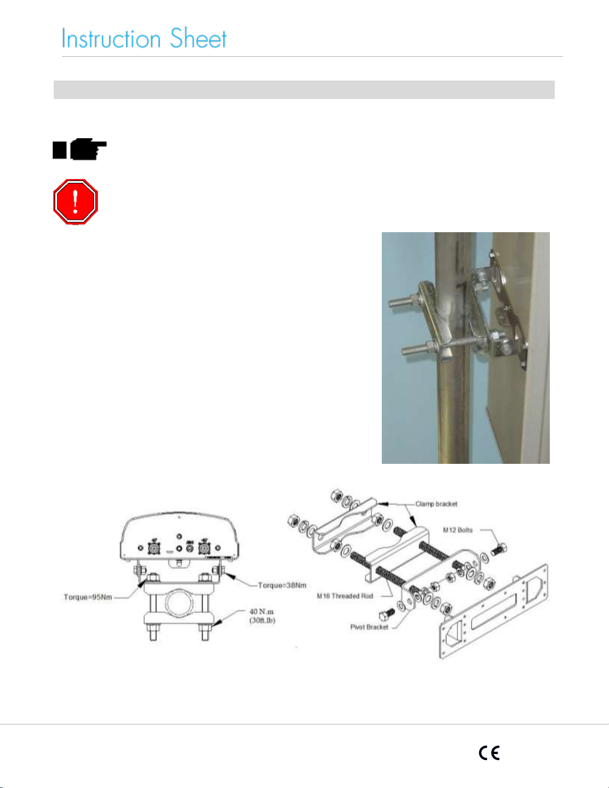
Figure 3. Fixed Downtilt Mounting
Bracket Exploded Assembly
Figure 2. Fixed Downtilt Mounting
Bracket Assembled to Antenna
Figure 1: Correctly Assembled
Mounting Bracket for
Fixed Downtilt Antenna
Installation Instructions - Fixed Downtilt Mounting Kit F-118-GL-E
Assemble three mounting kits as per Figures 2 of this document
1. Attach the mounting kit assembly to the antenna, before trying to clamp the
brackets to the pole.
Clamp brackets can clamp pipe diameters between 50mm (2") & 115mm (4.5").
For high wind locations the minimum recommended pole diameter is 88mm
(3.5").
Page 3

www.commscope.com
© 2015 CommScope, Inc. All rights reserved.
Visit our website at www.commscope.com or contact your local CommScope representative or BusinessPartner for more information.
All trademarks identified by ® or ™ are registered trademarks or trademarks, respectively, of CommScope, Inc. A997-0076 F (10/16)
Page 3 of 5
A997-0076
Fixed Downtilt
Antennas
Manual Electrically
Adjustable Downtilt
Antennas
AISG Compliant
Adjustable Downtilt
Antennas - Fitted
with Remote Downtilt
Adjustment
The beam downtilt is factory set.
The beam downtilt below the horizon is by rotating the hex
socket located at the bottom of the antenna (see Figure 4).
Turning the hex socket in a clockwise direction increases the
beam downtilt below the horizon. Turning the hex socket in an
anti-clockwise direction decreases the beam downtilt below the
horizon. Beam downtilt setting can be read off the scale at the
base of the antenna.
AISG Compliant antennas are compatible with AISG compliant
control unit equipment. For operation of downtilt using AISG
compliant controllers see the controller documentation.
Tilt adjust and
scale
(Band 1)
AISG
interface
+45
-45
+45
+45
-45
Band 2
Band 1
Figure 4: Single Band, 7-16
Connector, slimline antenna with
connections labelled
Figure 5: Dual Band, 7-16
connector, slimline antenna with
connections labelled.
(Fixed Tilt Antenna Pictured)
Note: The phase center of Band 2 is situated
above that of Band 1.
Operation of Antennas
WARNING: During downtilt adjustment ensure the hex socket is not turned past
the minimum tilt or past the maximum tilt as shown on the downtilt indicator
scale. Forcing the hex adjustment beyond this point may lead to damage of the
downtilt mechanism. Using power drills and electric screwdrivers to adjust
downtilt may also lead to damage of the downtilt mechanism.
Page 4

www.commscope.com
© 2015 CommScope, Inc. All rights reserved.
Visit our website at www.commscope.com or contact your local CommScope representative or BusinessPartner for more information.
All trademarks identified by ® or ™ are registered trademarks or trademarks, respectively, of CommScope, Inc. A997-0076 F (10/16)
Page 4 of 5
A997-0076
-45
+45
-45
+45
Tilt adj & scale
(Band 1)
AISG Interface
Tilt adj & scale
(Band 2)
Tilt adj & scale
(Band 2)
Tilt adj & scale
(Band 1)
-45
+45
AISG Interface
Tilt adj & scale
(Band 1)
-45 +45
Tilt adj & scale
(Band 3)
Tilt adj & scale
(Band 2)
-45 +45
-45 +45
AISG Interface
AISG Interface
Tilt Adjust & Scale
Figure 6: Dual band, 7-16
connector, antenna with
connections labelled.
Figure 7: Diplexed dual band,
7-16 connector antenna with
connections labelled.
Figure 8: Tri band, 7-16
connector, antenna with
connections labelled.
Note: The phase center of Band 3 is
situated above that of Band 2.
Figure 9: Single band, 7-16
connector, vertically polarized
slimline antenna with
connections labelled.
Electrically
Adjustable
Downtilt Antennas
– Indicator Scale
The downtilt angle in degrees below the horizon is read from the angle
indicator scale. The downtilt scale is read from face of the antennas
base plate at the point where the scale protrudes. As the downtilt is
increased, the indicator scale protrudes further past the face, revealing
further graduations of degrees.
Figures 4, 5, 6, 7 and 8 show the configuration of the positive and negative slant polarization
ports for single and multi band antennas. The tilt adjuster scale and port for remote interface is
also highlighted.
Page 5

www.commscope.com
© 2015 CommScope, Inc. All rights reserved.
Visit our website at www.commscope.com or contact your local CommScope representative or BusinessPartner for more information.
All trademarks identified by ® or ™ are registered trademarks or trademarks, respectively, of CommScope, Inc. A997-0076 F (10/16)
Page 5 of 5
A997-0076
Remote Electrical
Tilt Connection
The AISG connector fitted to the antenna is designed to accept any
AISG compliant cable assembly. After ensuring both connectors are dry,
push in the mating connector, then tighten.
Using excessive torque may damage the AISG connection in the
antenna.
The RF connectors fitted to the antenna are designed to fit
jumper cables with a corresponding male connector. After
ensuring both mating connectors are dry push the male connector in
and tighten the connector coupling to the correct torque setting.
If needed or as required by local procedures a weatherproofing kit
may then be fitted to the connection.
If the RF connectors are tightened beyond the recommend torque the
RF connection to the antenna may be damaged.
RF Cable
Connection
 Loading...