

Page 1

CommScope Era
™
Fiber Low Power Carrier Access Point
Installation Guide • M0201ANC_uc • June 2019
Page 2

DISCLAIMER
This document has been developed by CommScope, and is intended for the use of its customers and customer support
personnel. The information in this document is subject to change without notice. While every effort has been made to
eliminate errors, CommScope disclaims liability for any difficulties arising from the interpretation of the information
contained herein. The information contained herein does not claim to cover all details or variations in equipment, nor to
provide for every possible incident to be met in connection with installation, operation, or maintenance. This document
describes the performance of the product under the defined operational conditions and does not cover the performance
under adverse or disturbed conditions. Should further informatio n be d esir ed, or shou ld par ticu lar pr oblem s ari se whi ch ar e
not covered sufficiently for the purchaser's purposes, contact CommScope.
CommScope reserves the right to change all hardware and software c
haracteristics without notice.
COPYRIGHT
© 2019 CommScope, Inc. All Rights Reserved.
This document is protected by copyri
transmitted, in any form or by any means, electronic, mechanical photocopying, recording, or otherwise without the prior
written permission of CommScope.
For patents see www.cs-pat.com.
ght. No part of this document may be reproduced, stored in a retrieval system, or
TRADEMARKS
All trademarks identified by ® or ™ are registered trademarks or trademarks, respectively, of CommScope, Inc. Names of
other products mentioned herein are used for identification purposes only and may be trademarks and/or registered
trademarks of their respective companies.
Andrew Wireless Systems GmbH, 17-June-2019
Page 3

TABLE OF CONTENTS
Document Overview .................................................................................................................................................................................. 1
Document Revision History ..............................................................................................................................................................................1
Document Cautions and Notes......................................
Abbreviations Used in this Guide ..................................................................................................................................................................... 3
CommScope Part Numbers .............................................................................................................................................................................. 3
...................................................................................................................................2
Era System Overview .................................................................................................................................................................................
Fiber CAP L Overview.................................................................................................................................................................................
Connectors and LED for the Fiber CAP L...........................................................................................................................................................6
CAP L Accessories and Options..........................................
Fan Kit......................................................................................................................................................................................................... 7
Mounting and Power Kits...........................................................................................................................................................................8
OCTIS Kits ........................................................
SFP+ Modules.............................................................................................................................................................................................9
Plan and Prepare for a Fiber CAP L Installation.........................................................................................................................................
Maximum Number of Fiber CAP Ls Supported in an Era System ......................................
Cascade Rules for Fiber CAP Ls.......................................................................................................................................................................11
Cat6A Cable Requirements for Ethernet Devices...........................................................................................................................................12
Safely Working with Era Hardware................................
Health and Safety Precautions.................................................................................................................................................................12
Property Damage Warnings ..................................................................................................................................................................... 13
General Installation Safety Requirements ..........................
Guard Against Damage from Electro-Static Discharge.............................................................................................................................13
Compliance...............................................................................................................................................................................................14
Equipment Symbols Used / Compliance .............................
Required Antenna Distances....................................................................................................................................................................16
Determine the Power Consumption of the CAP L .......................................................................................................................................... 17
Determine the CAP L Installation Site................................................
CAP L Dimensions.....................................................................................................................................................................................18
Mounting Dimensions for a CAP L with the Flat Mounting Bracket Kit .............................................................................................18
Mounting Dimensions for Two CAP Ls Mounted with the Dual Mounting Kit .............................
Mounting Dimensions for a CAP L Mounted with the CAP L Hybrid Fiber Splice Box Kit..................................................................20
Mounting Dimensions for a CAP L Mounted with the AC/DC Power Supply Kit................................................................................21
CAP L Weights .........................................................
Extended CAP L Temperature Operation.................................................................................................................................................22
Recommended Tools and Material ................................................................................................................................................................23
Unpack and Inspect the CAP L and Optional Accessories......................................
Obtain the Required Materials....................................................................................................................................................................... 23
Mount the Fiber CAP L .............................................................................................................................................................................
General Mounting Cautions.......................................
Mounting a CAP L with a Flat Mounting Bracket Kit..............................
Attach the Flat Mounting Bracket Kit to the CAP L .................................................................
Flat-Surface Mount a CAP L.................................................................
Wall Mount a CAP L..................................................................................................................................................................................29
Mounting Orientation for Wall Mounts............................
Wall Mount a CAP L Using a Flat Mounting Bracket Kit..................................................................................................................... 30
Mounting Two CAP Ls with a Dual Mounting Kit............................................................................................................................................31
Mounting a CAP L with an AC/DC Power Supply Kit..................................
Wiring the AC/DC Power Supply Kit. .............................................................................................................................................................. 38
Mounting a CAP L with a Hybrid Fiber Splice Box Kit .....................................................................................................................................43
Prepare for CAP L Hybrid Fiber Splice Box Kit Installation ......................
Assembling and Wiring the Hybrid Fiber Splice Box ................................................................................................................................43
Wire the Hybrid Fiber Splice Box .......................................................................................................................................................44
Wire a Hybrid Fiber Splice Box for 4-Wi
Wire a Hybrid Fiber Splice Box for 2-Wire Power without Limited Power Source ............................................................................49
Wire a Hybrid Fiber Splice Box to Cascade Two CAP Ls with the 2-Wire Power Configuration......................................................... 50
Wire a Hybrid Fiber Splice Box to Cascade Two CAP Ls with the 4-Wire Power Configuration...........................
Wall Mount a CAP L Using a CAP L Hybrid Fiber Splice Box Kit................................................................................................................52
Ceiling Mount a CAP L.....................................................................................................................................................................................54
Ceiling Mount a CAP L without a Fan Kit.............................................
Ceiling Mount a CAP L with a Fan Kit ....................................................................................................................................................... 54
re Power with Limited Power Source.................................................................................. 47
...............................................................................................................................7
...........................................................................................................................................9
............................................................................. 10
.................................................................................................................................12
.....................................................................................................................13
.....................................................................................................................16
.............................................................................................................17
..................................................... 19
.................................................................................................................................21
......................................................................................... 23
.....................................................................................................................................24
.........................................................................................................25
................................................................. 26
.....................................................................................................27
.................................................................................................................29
.....................................................................................................38
................................................................................................. 43
..............................51
.....................................................................................................54
4
5
10
24
M0201ANC_uc CommScope Era™ Fiber Low Power Carrier Access Point Installation Guide
© June 2019 CommScope, Inc. Page iii
Page 4

Table of Contents
Connect the Cables to the Fiber CAP L...................................................................................................................................................... 55
Ground the Fiber CAP L (Optional) .................................................................................................................................................................55
Connect the Fiber CAP L to a Passive RF Antenna.......................................................................................................................................... 56
Clean the RF Cable Connectors ...................................
Connect the Passive RF Antenna..............................................................................................................................................................59
Connect the Fiber CAP L to a Classic CAN or TEN........................................................................................................................................... 60
Cascade a Secondary Fiber CAP L (Optional).....................................................
Connect an External Ethernet Device (Optional)............................................................................................................................................ 62
Connect to Vdc Power ....................................................................................................................................................................................62
.............................................................................................................................57
............................................................................................. 61
Powering on a Fiber CAP L .......................................................................................................................................................................
CAP L Maintenance..................................................................................................................................................................................
Remove a CAP L from a Wall or Ceiling Mount .............................................................................................................................................. 63
Preventative CAP L Maintenance for CAP Ls with the Fan Kit Option.......................................
Contacting CommScope ...........................................................................................................................................................................
CMS Global Technical Support ....................................................................................................................................................................... 64
Telephone Helplines................................................
Online Support .........................................................................................................................................................................................64
Waste Electrical and Electronic Equipment Recycling....................................................................................................................................64
Hardware to Software Mapping Information........................
Mobility Solutions Technical Training.............................................................................................................................................................65
Accessing Era/ION-E Series User Documentation .......................................................................................................................................... 66
.................................................................................................................................64
.........................................................................................................................65
..................................................................... 63
62
63
64
CommScope Era™ Fiber Low Power Carrier Access Point Installation Guide M0201ANC_uc
Page iv © June 2019 CommScope, Inc.
Page 5

DOCUMENT OVERVIEW
Th ere ar e tw o var iant s av ailab le f or Lo w Pow er Ca rrier Acce ss P oints (CAP L): one variant has an optical fiber
interface (Fiber CAP L), and the other has a copper interface (Copper CAP L). This installation guide provides
a product overview and installation instructions fo
refer to
Era/ION-E Series User Documentation” on
the CommScopeEra™CopperLowPowerCarrierAccessPointInstallationGuide; see "A c c e s s i n g
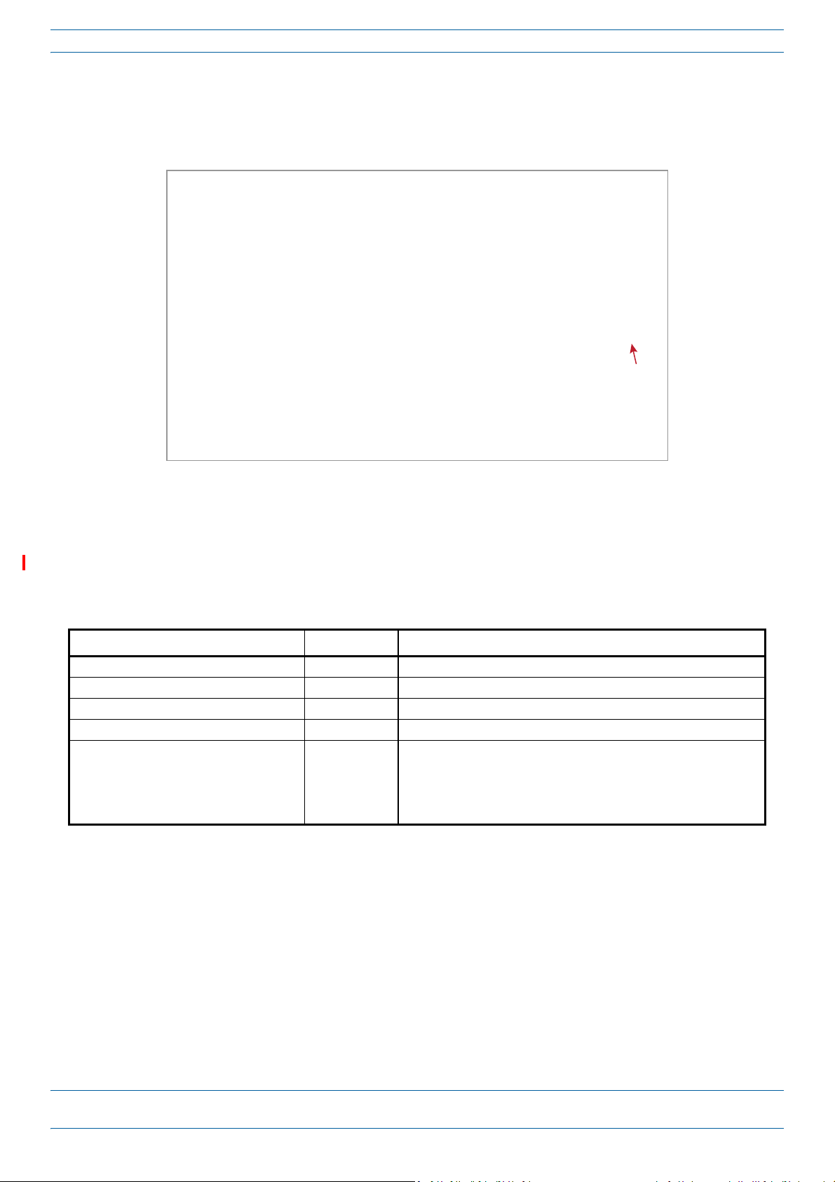
page 66). Ta bl e 1 lists the CAP L models that this installation guide
supports.
Table 1. Supported CAP L Models
Part Number 1 Model Name
7770203-000x CAP L 17E/17E/23/23
7770209-000x CAP L 18/21/26/26
7770356-000x CAP L 17E/17E/19/19
7776595-000x CAP L 9/18/18/21
7776596-000x CAP L 7/80-85/17E/19
7776597-000x CAP L 17E/19/23/25TDD
7776598-000x CAP L 9/18/21/26
7776641-000x CAP L 8/9/18/21
7776643-000x CAP L 8/18/21/26
1 The “-000x” suffix provides information as to
er the CA P L has a Fiber or Copper
eth
wh
interface, and the power and Fan Kit options.
Contact your local sales representative for
further information.
r the Fiber CAP L. (For information on the Copper CAP L,
For information on how to find the minimum software requirements for Era hardware, refer to "Hardware
to Software Mapping Information” on page 65.
Document Revision History
This is the third release of the CommScopeEra™FiberLowPowerCarrierAccessPointInstallationGuide.
M0201ANC_uc CommScope Era™ Fiber Low Power Carrier Access Point Installation Guide
© June 2019 CommScope, Inc. Page 1
Page 6
Document Overview
Document Cautions and Notes
This document may contain any of the following notes, cautions, and warning icons.
The icon to the left is used to indicate a caution or warning. Cautions and warnings indicate operations or
steps that could cause personal injury, induce a safety problem in a managed device, destroy or corrupt
information, or interrupt or stop services.
The icon to the left indicates a caution or warning that pertains to laser equipment.
The icon to the left indicates a caution or warning that pertains to Radio Frequency (RF).
The icon to the left indicates that the hardware is susceptible to Electro-Static Discharge (ESD) damage.
The icon to the left indicates a caution or warning that pertains to an electrical hazard.
The icon to the left indicates a Note. Notes provide information about special circumstances.
CommScope Era™ Fiber Low Power Carrier Access Point Installation Guide M0201ANC_uc
Page 2 © June 2019 CommScope, Inc.
Page 7

Document Overview
Abbreviations Used in this Guide
AP Access Point ISDE Innovation, Sciences et Développement économique Canada
AUX Auxiliary ISED Innovation, Science and Economic Development Canada
C Celsius kg Kilogram
CAN Central Area Node LED Light Emitting Diode
CAP L Low Power Carrier Access Point LPS Limited Power Source
CAP M Medium Power Carrier Access Point MHz Megahertz
Cat Category mm Millimeter
CAT Copper Transport MMF Multi-Mode Fiber
dB Decibel N/A Not Applicable
dBm Decibel-milliwatts OPT Optical Transport
DC Direct Current PN Part Number
DCCS Distributed Coverage and Capacity Solutions RAN Regional-Area Network
EFTA European Free Trade Association RF Radio Frequency
EMC Electromagnetic Compatibility RU Rack Unit
EMEA Europe, Middle East, Africa SFP Small Form-Factor Pluggable
EU European Union SMF Single-Mode Fiber
F Fahrenheit TEN Transport Expansion Node
FCC Federal Communications Commission UAP Universal Access Point
Gb Gigabyte Vdc Volts, direct current
GHz Gigahertz W Watts
ION Intelligent Optical Network
CommScope Part Numbers
The CommScope part numbers in this installation guide are in the format of nnnnnnn-xx, where the “-xx”
suffix indicates the latest release. Contact your local CommScope sales representative for the current release
part number.
M0201ANC_uc CommScope Era™ Fiber Low Power Carrier Access Point Installation Guide
© June 2019 CommScope, Inc. Page 3
Page 8

Era System Overview
ERA SYSTEM OVERVIEW
CommScope Era™ coordinates wireless capacity throughout the entire coverage area via a single centralized
head-end location or from an operator’s existing C-RAN hub. Based on ION-E
cost-efficient standard IT cabling as ION-E and is compatible with ION-E deployments. Era systems bring
together licensed wireless and power, plus Gigabit Ethernet for WiFi into one wireless system that can scale
to building size and is technology and spectrum agnostic and adaptive. An Era system comprises the
components listed below.
®
, Era operates on the same
• Ce
ntralAreaNod
the signals from multiple operators and distributes those signals within a venue or multiple venues.
There are two configuration modes available for the CAN: Classic and Switching.
– The ClassicCAN c
in a centralized space in the same venue as the Classic CAN. You install RF Donor (RFD) Cards and
CPRI Digital Donor (CDD) Cards in a Classic CAN, which digitizes the analog BTS signals from the RFD
Cards and combines those with the BBU CPRI digital signals from the CDD Cards, and then distributes
the RF signals to the TENs. The TENs then provide the RF signals to the Access Points (APs). The
Classic CAN also supports APs that are directly connected to CAT or OPT Cards installed in the Classic
CAN chassis. Wide-area Integration Nodes (WINs) are not supported by a Classic CAN. Users have full
and flexible control of all signal routing via the Era GUI.
– The SwitchingCAN configuration is appro
bring in baseband signals from multiple remote locations to fully leverage the C-RAN architecture in
their hubs. All operator Baseband signals (analog BTS and BBU CPRI) are supplied to the Switching
CAN by the WINs, so no RFD or CDD Cards can be installed in the Switching CAN. The Switching CAN
then combines the signals from all WINs and distributes those signals to the TENs, and the TENs
provide the signals to the APs. APs are not directly connected to a Switching CAN. Users have full and
flexible control of all signal routing via the Era GUI.
This guide uses “CAN” to collectively refer to Central Area Nodes. When information pertains to a specific
CAN mode, “Classic CAN” and “Switching CAN” will be used.
e(CAN)—provides server-level control and primary signal distribution. It combines
onfiguration is appropriate for when all the BTS and Baseband sources are located
p
riate for when WINs are required to allow operators to
• Wide-AreaInte
makes C-RAN possible in Era by allowing operators to bring in signals from multiple remote locations
kilometers away. You install RFD and CDD Cards in the WIN, which takes the analog BTS signals from the
RFD Cards and combines those with the BBU CPRI digital signals from the CDD Cards, and distributes the
RF sources to a Switching CAN.
• TransportExp
located throughout the venue coverage area. A single TEN can support, dependent on the AP type and
powering method, 12 to 32 Access Points (APs), which greatly reduces the number of fiber runs between
the head-end and each AP.
• AccessPoin
downlink, an AP converts data arriving at the AP to analog signals and sends them to an antenna. On the
uplink, received signals are digitized and serialized into data streams which are sent back to the Classic
CAN or TEN. APs provide pass-through support for WiFi, IP cameras, or other devices over a common
cable. An AP can be any of the Universal Access Points or Carrier Access Points.
This guide uses “Access Point (AP)” to collectively refer to all versions of the Universal Access Point (UAP)
and the Carrier Access Point (CAP). “Fiber APs” collectively refers to the CAP H, CAP M, and the Fiber
CAP L. When information pertains to a specific AP type, that AP will be identified.
grationNode(WIN)—interfaces between a Switching CAN and RF sources, which
a
nsionNode(TEN)—is an expansion node connected to the CAN via fiber and can be
t(AP)—connects a Classic CAN or TEN to antennas or other wireless devices. On the
CommScope Era™ Fiber Low Power Carrier Access Point Installation Guide M0201ANC_uc
Page 4 © June 2019 CommScope, Inc.
Page 9

Fiber CAP L Overview
e-POI
Classic
CAN
eNode B
TEN
UAP
UAP
UAP
UAP
* Power can be on AP side (AC or DC)
or be remote with composite fiber (DC)
TEN
Cat6A cable
Fiber
Power
Power*
Fiber CAP L
Fiber CAP L
Fiber CAP L
Fiber CAP L
Fiber CAP L
Fiber CAP L
Fiber CAP L
Fiber CAP L
Fiber CAP L
Fiber CAP L
FIBER CAP L OVERVIEW
There is one Optical Fiber and two Copper CAP L interface variants. This installation guide describes the Fiber
CAP L, which interfaces with a Classic CAN or TEN via an optical link. This allows the Fiber CAP L to provide
data over Single-Mode Fiber
External AC/DC or remotely thr
On the downlink, the Fiber CAP L converts data arriving at the CAP L to analog signals and sends them to the
tenna
An
ports. On the uplink, received signals are digitized and serialized into data streams, which are sent
back to the Classic CAN or TEN. Figure 1 shows how a Fiber CAP L can be deployed in an Era system.
(SMF) or Multi-Mode Fiber (MMF). Power for Fiber CAP Ls is provided over
ough hybrid fiber.
Figure 1. Fiber CAP L in an Era System
The Fiber CAP L
• has the following temperature ranges
– without a Fan Kit, it is passively cool
ed with a temperature range of: -33°C to +40°C (-27.4°F to
104°F); see also "Extended CAP L Temperature Operation” on page 22.
– with a Fan Kit, the Fiber CAP L
see also "Fan Kit” on page 7.
• is o
• has a typical power consumption that dependent on the model ranges from
M0201ANC_uc CommScope Era™ Fiber Low Power Carrier Access Point Installation Guide
© June 2019 CommScope, Inc. Page 5
utdoor rated (IP67)
Antenna Distances” on page 16.
has an increased maximum operating temperature of 55°C (131°F);
92 to 103W; see "Required
Page 10

Fiber CAP L Overview
1
2
3
4
5
6
7
8
9
Connectors and LED for the Fiber CAP L
Figure 2 and Tab le 2 identify the Fiber CAP L connectors and its LED; corresponding connectors are shown.
Figure 2. CAP L Connectors and LED
Table 2. Function of the CAP L Connectors and LED
REF # Label Description Function
1, 4 ANT 3, ANT 4 Not available; connector is plugged.
2 ANT 1 4.3-10 RF connector Connect to two separate external ant
3 ANT 2
5 Power LED
(Unlabeled)
6 Unlabeled Proprietary 4-pin 36
7 2 Optical Port 2 If th e CAP L is functioning as a Primary CAP L in a cascade, Optical Port 2 connects to Optical Port
8 1 Optical Port 1 Connects to a Classic CAN or TEN
9 A RJ45 Auxiliary port Connects to external Ethernet dev
Power LED
to 60 Vdc Power
connector
via 50 coaxial cable. Each connector supports two RF bands. The end of th
that connects to an ANT connector can be either a push-pull or a threaded connector. The ANT
1 and ANT 2 ports ship with dust caps that can be discarded upon unit installation.
See "Powering on a Fiber CAP L” on page 62.
Connects to a DC power supply, or to a Hybrid Fiber Junction Box; all four pins must be
terminated. The CAP L does not ship with any power cables preinstalled; you need to or
power cable assembly that is appropriate for this installation:
• 7774061-xx: Cable Assembly, CAP L Local Power Jumper, 0.5m
• 7816237-xx: Cable Assembly, CAP L Local Power Jumper, 3m
1 of the Secondary CAP L via the Optical OCTIS Kit (PN
provide the main signal interface. Optical transport occurs over Single Mode Fiber (SMF) or
Multi Mode Fiber (MMF). Port 2 ships with factory-installed EMI/weatherproof plug and must
remain plugged if not in use. Graphic shows the OCTIS connector in blue.
provides the main signal interface; if Secondary CAP L in a cascade, Optical Port 1 connects to
Optical Port 2 of
Multi Mode Fiber (MMF). Uses the Optical OCTIS Kit (PN 7770612), which ships with the unit.
Port 1 ships with a dust cap that can be discarded upon unit installation. Graphic shows the
OCTIS connector in blue.
appropriate CAT cable for the protocol; this model supports a 1000 BASE-T and 802.3at Class 4
Power over Cat6A Ethernet connection. Maximum attached cable length is 3 meters (9.8 feet).
For information on the Auxiliary port in cascades, see "Cascade Rules for Fiber CAP Ls” on
page 11. Port A ships with factory-installe
not in use. (Graphic shows the port populated
which must be ordered separately—see "OCTIS Kits” on page 9.)
the Primary CAP L. Optical transport occurs over Single Mode Fiber (SMF) or
ennas or to two por
(
possibly through a local Hybrid Fiber Junction Box) and
i
ces such as WiFi and IP cameras. Cabling is via the
d EMI/weatherproof plug and must remain plugged if
with an OCTIS Ethernet connector PN 7760652
ts on a cross-polarized dual antenna
e 50 coaxial cable
der the
7770612), which ships with the unit, to
CommScope Era™ Fiber Low Power Carrier Access Point Installation Guide M0201ANC_uc
Page 6 © June 2019 CommScope, Inc.
Page 11

Fiber CAP L Overview
Fan Kit
CAP L Accessories and Options
The Fiber CAP L accessories and options are described in the following sections:
• "Fan Kit” on page 7
• "Mounting and Power Kits” on page 8
• "OCTIS Kits” on page 9
Fan Kit
Figure 3 shows the optional Fan Kit that is an integrated shroud that fits over a Fiber CAP L enclosure to
extend the upper ambient temper
• is IP55 rated
• increases the maximum operating temperature to 55°C (131°F)
ature range. The Fan Kit
• adds 3W power consumption to the Fiber CAP L; se
• is factory ins
talled but can be replaced in the field.
e "Required Antenna Distances” on page 16.
Figure 3. CAP L with the Optional Fan Kit
M0201ANC_uc CommScope Era™ Fiber Low Power Carrier Access Point Installation Guide
© June 2019 CommScope, Inc. Page 7
Page 12
Fiber CAP L Overview
Fan
Interface
port
Figure 4 shows the pr oprietary 8-pin Fan Interf ace port, whic h is only available on Fiber CAP L units that ship
with the factory-installed Fan Kit. If the Fiber CAP L being installed includes the Fan Kit option, the Fan
Interfa
ce port will be cabled to the Fan Kit at the factory. If the Fiber CAP L being installed does not inclu
de
the Fan Kit option, the Fan Interface port will be plugged.
Figure 4. Fan Interface Port
Mounting and Power Kits
CAP L Mounting and Power Kits are not included with the CAP L and must be ordered separately. Mounting
and Power Kits are described in the applicable installation process:
Table 3. Mounting and Power Kits
Mounting/Power Kit CommScope PN See
Flat Mounting Bracket Kit 7774353-xx "Mounting a CAP L with a Flat Mounting Bracket Kit” on page 25
Dual Mounting Kit 7815440-xx "Mounting Two CAP Ls with a Dual Mounting Kit” on page 31
Box Kit” on page 43
Hybrid Fiber Splice Kit 7781091-xx "Mounting a CAP L with a Hybrid Fiber Spl
Power Supply/Hybrid Fiber Mounting Kit 7774354-xx "Mounting a CAP L with an AC/DC Power Supply Kit” on page 38
240W Local AC Power Supply Kit
no AC Input Cord 7775087-xx
with AC Input Cord 7809798-xx
for Plenum Space 7809823-xx
"Mounting a CAP L with an AC/DC Power Supply Kit” on page 38
ice
CommScope Era™ Fiber Low Power Carrier Access Point Installation Guide M0201ANC_uc
Page 8 © June 2019 CommScope, Inc.
Page 13
Fiber CAP L Overview
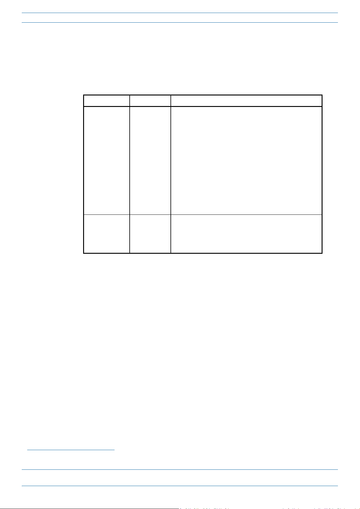
OCTIS Kits
All Fiber CAP Ls include one OCTIS1 Kit for the primary interface to the Classic CAN or TEN. Regardless of
which OCTIS Kit ships with the CAP L, it will plug int o Port 1 on the C AP L. Y ou m ust o rder an ad dit ional OCT IS
Ki
t to cascade two CAP Ls, or to attach an auxiliary Ethernet device; which OCTIS Kit you should ord
identified in Tabl e 4.
Table 4. CAP L OCTIS Kits
Kit Name CommScope PN Description
Optical OCTIS Kit 7770612 T hi s is th e SF P+ con ne ctor th at yo u u se t o c asca de a Se co nda ry Fiber
CAP L; one Optical OCTIS Kit ships with each Fiber CAP L. Use as
follows:
• Optical Port 1—to connect the CAP M to a Classic CAN or TEN.
• Optical Port 2—to cascade a second CAP M.
• SFP+ Module must be ordered separ
part of the Optical OCTIS Kit.
• Ships with the following grommets:
– 6mm nominal diameter for use with cabl
from 4.8-5.8
– 7mm nominal diameter for use with cables with OD range
from 5.8-6.8
– 8mm nominal diameter for use with cables with OD range
from 6.8-7.8
Ethernet OCTIS Kit 7760652 This is the RJ-45 connector that you use to attach an auxiliary
Ethernet device. The Ethernet OCTIS Kit must be ordered
separately.
ely, it is not included as
at
es with OD range
er is
SFP+ Modules
The SFP+ Module installed in an OPT Card port is paired with another in Optical Port 1 of the Fiber CAP L. For
a complete list of available SFP+ Modules, refer to the Era™SolutionOrderingGuide.
1 OCTIS is a trademark of RADIALL.
M0201ANC_uc CommScope Era™ Fiber Low Power Carrier Access Point Installation Guide
© June 2019 CommScope, Inc. Page 9
Page 14
Plan and Prepare for a Fiber CAP L Installation
PLAN AND PREPARE FOR A FIBER CAP L INSTALLATION
Do the following before beginning installation.
1 Review and know the information in "Maximum
page 10.
1 Rev
2 Review and know the information in "Saf
3 "Required Antenna Distances” on page 16.
4 "Determine the CAP L Installation Site” on page 17, which includes understanding and meeting
5 Map out all
6 Identify and obtain all tools and mater
7 Obtain any accessories required for this installation; see "CAP L Accessories and Options” on page 7.
8 "Unpack and Inspect the CAP L and Optional Accessories” on page 23.
iew and know the information in "Cascade R
ely Working with Era Hardware” on page 12.
requirements for:
• "Recommended Tools and Material” on page 23
• "CAP L Weights” on page 21
• "Extended CAP L Temperature Operation” on page 22
• "CAP L Dimensions” on page 18.
cable runs.
ials required to complete the installation as described in
"Recommended Tools and Material” on page 23.
Number of Fiber CAP Ls Supported in an Era System” on
ules for Fiber CAP Ls” on page 11.
Maximum Number of Fiber CAP Ls Supported in an Era System
When installing a Fiber CAP L, you must observe the following rules.
• SMF or MMF connects the Fiber CAP L via its Op
• You connect CAP Ls to a
– Each OPT Card has four 10 Gbps ports (labeled 1 - 4) for
– You can connect up to 4 CAP Ls
CAN.
Fiber CAP Ls must be connected to OPT Cards installed in Slots L1, L2, L3, or L4 in a TEN or Classic CAN.
OPT Cards installed in WCS Slots L5 - L8 cannot be used to connect APs.
n OPT Card installed in Slots L1, L2, L3, or L4 in the TEN or Classic CAN.
per OPT Card for a total of 16 Primary and 32 total, per TEN or Classic
tical Port 1 to the OPT Card.
fiber connections.
CommScope Era™ Fiber Low Power Carrier Access Point Installation Guide M0201ANC_uc
Page 10 © June 2019 CommScope, Inc.
Page 15

Plan and Prepare for a Fiber CAP L Installation
Cascade Rules for Fiber CAP Ls
When cascading a Secondary Fiber CAP L or an external Ethernet device such as WiFi or an IP camera, you
must observe the following rules.
n a cascade, the CAP L connected directly to the Classic CAN or TEN is the Primary Fiber CAP L, and the
• I
CAP L that connects to the Primary Fiber CAP L is the Secondary Fiber CAP L.
• The cascaded unit must use the same transport type—you
CAP L.
• The
• The
• SMF or MMF from Optical Port 2
• You can connect th
• A
• To
total 320 MHz RF bandwidth is shared between the two cascaded units, but can be shared unevenly;
that is, with more bandwidth going to either the Primary or Secondary Fiber CAP L—either CAP L can
smit all the 320 MHz RF bandwidth or any subset of it.
tran
Primary and Secondary Fiber CAP Ls power up as soon as power is applied to them. In a cascade, the
Era GUI discovers and readies the Primary CAP L for RF first, and then the Secondary CAP L will be
vered and readied for RF. For information on the Power LED behavior, see "Powering on a Fiber
disco
CAP L” on page 62.
of the Primary Fiber CAP L connects to Optical Port 1 of the Secondary
Fiber CAP L.
e following to the Primary Fiber CAP L
– a Secondary Fiber CAP L
– an
– b
on the Primary Fiber CAP L, it cannot be connected to the Secondary CAP L.
page 9.
Ethernet device
oth a Secondary Fiber CAP L (Port 2) and an Ethernet device (Aux Port).
cascaded CAP L pair can support one auxiliary device; the auxiliary device must be connected to Port A
add a Secondary AP, you must add an Optical OCTIS kit to the Primary CAP L, see "OCTIS Kits” on
cannot cascade a Copper CAP L to a Fiber
• To
page 9.
add an Ethernet device, you must add an RJ45 OCTIS kit to the Primary CAP L, see "OCTIS Kits” on
M0201ANC_uc CommScope Era™ Fiber Low Power Carrier Access Point Installation Guide
© June 2019 CommScope, Inc. Page 11
Page 16

Plan and Prepare for a Fiber CAP L Installation
Cat6A Cable Requirements for Ethernet Devices
If you connect an Ethernet device to a Fiber CAP L, you must observe the following rules.
• Plenum rated cable must be used whenever it is required by local electrical
• Shielded twisted pair is not required unless operating in a high RF
• CommScope strongly recommends using fa
• 24 AWG Cat6A cabling is sufficient for the cable run between the
• The maximum attached cable length from Port A on the Fiber CAP L
feet); see Figure 5.
From a Fiber CAP L to an Ethernet device,
Cat6A cannot exceed 3 meters (9.8 feet)
Fiber CAP L
Figure 5. Maximum Cat6A Cable Length between a Fiber CAP L and an Ethernet Device
ctory terminated and tested Cat6A Patch Cord.
24 AWG Cat6A Cable
I/EMI environment.
Fiber CAP L and the Ethernet device.
to the Ethernet device is 3 meters (9.8
Ethernet
Device
codes.
Safely Working with Era Hardware
The following sections provide important information that you should read and know before working with
any Era hardware. Observe all cautions and warnings listed in this section.
Health and Safety Precautions
A high leakage current ground (earth) connection to the Power Supply Unit (PSU) is essential before
making any other connections to the PSU.
Laser radiation. Risk of eye injury in operation. Do not stare into the laser beam; do not view the laser
beam directly or with optical instruments.
High frequency radiation in operation. Risk of health hazards associated with radiation from the
antenna(s) connected to the unit. Implement prevention measures to avoid the possibility of close
proximity to the antenna(s) while in operation.
CommScope Era™ Fiber Low Power Carrier Access Point Installation Guide M0201ANC_uc
Page 12 © June 2019 CommScope, Inc.
Page 17

Property Damage Warnings
Keep operating instructions within easy reach and make them available to all users.
Only license holders for the respective frequency range are allowed to operate this unit.
Read and obey all the warning labels attached to the unit. Make sure that all warning labels are kept in a
legible condition. Replace any missing or damaged labels.
Make sure the unit's settings are correct for the intended use (refer to the manufacturer product
information) and regulatory requirements are met. Do not carry out any modifications or fit any spare
parts, which are not sold or recommended by the manufacturer.
General Installation Safety Requirements
Plan and Prepare for a Fiber CAP L Installation
Wet conditions increase the potential for receiving an electrical shock when installing or using electrically
powered equipment. To prevent electrical shock, never install or use electrical equipment in a wet
location or during a lightning storm.
This system is a RF Transmitter and continuously emits RF energy. Maintain a minimum clearance from
the antenna as specified in Table 6 while the system is operating. Whenever p
L before servicing the antenna.
CAP
Do not remove caps from any of the connectors until instructed to do so.
The CAP L is to be used only with CommScope (NEC Class 2) or Limited Power Source Era Subrack, or
equivalent.
Guard Against Damage from Electro-Static Discharge
Electro-Static Discharge (ESD) can damage electronic components. To prevent ESD damage, always wear
an ESD wrist strap when working with Era hardware components. Not all Era hardware requires
grounding. For those Era hardware components for which grounding is required, connect the ground wire
on the ESD wrist strap to an earth ground source before touching the Era component. Wear the wrist
strap the entire time that you work with the Era hardware.
ossible, power down the
M0201ANC_uc CommScope Era™ Fiber Low Power Carrier Access Point Installation Guide
© June 2019 CommScope, Inc. Page 13
Page 18

Plan and Prepare for a Fiber CAP L Installation
]/[
][
][
2
4
cmmW
mW
cm
PD
P
D
Compliance
1 Notice: For installations, which have to comply with FCC RF exposure requirements, the antenna
se lect ion a nd in stal lat ion m ust b e com plet ed in a way to e nsure comp lian ce wi th th ose F CC re quir emen ts.
Depending on the RF frequency, rated output power, antenna gain, and the loss between the repeater and
antenna, the minimum distance D to be maintained between the antenna location and human beings is
calculated according to this formula:
where
• P (mW) is the radiated power at the
antenna, i.e. the max. rated repeater output power in addition to
the antenna gain minus the loss between the repeater and the antenna.
• PD (mW/cm²) is the allowed Power D
ensity limit acc. to 47 CFR 1.1310 (B) for general population /
uncontrolled exposures which is
– f (MHz) / 1500 for frequencies from 300MHz to 1500MHz
– 1 for frequencies from 1500MHz to 100,000MHz
R
F exposure com pliance may need to be addressed at the time of lice
nsing, as required by the responsible
FCC Bureau(s), including antenna co-location requirements of 1.1307(b)(3).
2 Notice: Fo
r installations which have to comply with European EN50385 exposure compliance
requirements, the following Power Density limits/guidelines (mW/cm²) according to ICNIRP are valid:
• 0.2 for frequencies from 10 MHz to 400 MHz
• F (MHz) / 2000 for frequencies from 400 MHz to 2 GHz
• 1 for frequencies from
3 Notice: Installation of th
2 GHz to 300 GHz
is equipment is in full responsibility of the installer, who has also the
responsibility, that cables and couplers are calculated into the maximum gain of the antennas, so that this
value, which is filed in the FCC Grant and can be requested from the FCC data base, is not exceeded. The
industrial boosters are shipped only as a naked booster without any installation devices or antennas as it
needs for professional installation.
4 Notice: Fo
r installations which have to comply with FCC/ISED requirements:
English:
This device complies with FCC Part 15. Operation is
subject to the following two conditions: (1) this
device may not cause interference, and (2) this device must accept any interference, including
interference that may cause undesired operation of the device.
This device complies with Health Canada's Safety Code. The installer of
this device should ensure that RF
radiation is not emitted in excess of the Health Canada's requirement. Information can be obtained at
http://www.hc-sc.gc.ca/ewh-semt/pubs/r
Changes or modifications not expressly approved by the party responsible f
adiation/radio_guide-lignes_direct-eng.php.
or compliance could void the
user's authority to operate the equipment.
AntennaStmtforISED:
This
device has been designated to o
perate with the antennas having a maximum gain of 9 dBi. Antennas
having a gain greater than 9 dBi are prohibited for use with this device without consent by ISED
regulators. The required antenna impedance is 50 ohms.
The antenna(s) used for this transmitter must be installed to pro
vide a minimum separation distance (as
specified in Tab le 6) from all persons and must not be co-located or operating in conjunction with any
CommScope Era™ Fiber Low Power Carrier Access Point Installation Guide M0201ANC_uc
Page 14 © June 2019 CommScope, Inc.
Page 19

Plan and Prepare for a Fiber CAP L Installation
other antenna or transmitter. Users and installers must be provided with antenna installation
instructions and transmitter operating conditions for satisfying RF exposure compliance.
French:
Cet appareil est conforme a F
CC Partie15. Son utilisation est soumise a Les deux conditions suivantes: (1)
cet appareil ne peut pas provoquer d'interferences et (2) cet appareil doit accepter Toute interference, y
compris les interferences qui peuvent causer un mauvais fonctionnement du dispositif.
Cet appareil est conforme avec Sante Ca
nada Code de securite 6. Le programme d'installation de cet
appareil doit s'assurer que les rayonnements RF n'est pas emis au-dela de I'exigence de Sante Canada. Les
informations peuvent etre obtenues:
http://www.hc-sc.gc.ca/ewh-semt/pu
Les changements ou modifications non expressement approuves par la par
bs/radiation/radio_guide-lignes_direct-eng.php
tie responsable de la
conformite pourraient annuler l'autorite de l'utilisateur a utiliser cet equipement.
AntenneStmtpo
Ce dispositif a ete desi
urISDE:
gne pour fonctionner avec les antennes ayant un gain maximal de 9 dBi. Antennes
ayant un gain plus grand que 9 dBi sont interdites pour une utilisation avec cet appareil sans le
consentement des organismes de re glementation d'ISDE. L'impedance d'antenne requise est 50 ohms.
L'antenne (s) utilise
(comme indique dans le Ta bl e 6) par rapport a tou
operant en conjonction avec une autre antenn
pour cet emetteur doit etre installe pour fournir une distance de separation minimale
te personnes et ne doit pas etre co-localisees ou
e ou emetteur. Les utilisateurs et les installateurs doivent
etre fournis avec des instructions d'installation de l'antenne et des conditions de fonctionnement de
l'emetteur pour satisfaire la conformite aux expositions RF.
5 Noti
ce: The unit complies with Overvoltage Category II. It also complies with the surge requirement
according to EN 61000-4-5 (fine protection); however, installation of an additional medium (via local
supply connection) and/or coarse protection (external surge protection) is recommended depending on
the individual application in order to avoid damage caused by overcurrent.
For Canada and US, components used to
reduce the Overvoltage Category shall comply with the
requirements of IEC 61643-series. As an alternative, components used to reduce the Overvoltage
Category may comply with ANSI/IEEE C62.11, CSA Certification Notice No. 516, CSA C22.2 No. 1, or UL
1449. Suitability of the component for the application shall be determined for the intended installation.
6 Noti
ce: Corresponding local particularities and regulations must be observed. For national deviations,
please refer to the respective documents included in the manual CD that is delivered with the unit.
7 Note:For a Class
This equipment has been tested and found to comply with the limits
B digital device or peripheral:
for a Class B digital device, pursuant
to part 15 of the FCC Rules. These limits are designed to provide reasonable protection against harmful
interference in a residential installation. This equipment generates, uses and can radiate radio frequency
energy and, if not installed and used in accordance with the instructions, may cause harmful interference
to radio communications. However, there is no guarantee that interference will not occur in a particular
installation. If this equipment does cause harmful interference to radio or television reception, which can
be determined by turning the equipment off and on, the user is encouraged to try to correct the
interference by one or more of the following measures:
• Reorient or relo
ncrease the separation between the equipment and receiver.
• I
• C
onnect the equipment into an outlet on a circuit different from that to which the receiver is
cate the receiving antenna.
connected.
• Consul
t the dealer or an experienced RF technician for help.
M0201ANC_uc CommScope Era™ Fiber Low Power Carrier Access Point Installation Guide
© June 2019 CommScope, Inc. Page 15
Page 20

Plan and Prepare for a Fiber CAP L Installation
8 Notice: For a Class A digital device or peripheral.
This equipment has been tested and found to comply with the limits for
a Class A digital device, pursuant
to Part 15 of the FCC Rules. These limits are designed to provide reasonable protection against harmful
interference when the equipment is operated in a commercial environment. This equipment generates,
uses, and can radiate radio frequency energy and, if not installed and used in accordance with the
instruction manual, may cause harmful interference to radio communications. Operation of this
equipment in a residential area is likely to cause harmful interference in which case the user will be
required to correct the interference at his own expense.
9 Note:T
his unit complies with European sta
ndard EN60950-1 / EN62368-1.
Equipment Symbols Used / Compliance
Please observe the meanings of the following symbols used in our equipment and the compliance warnings
listed in Tabl e 5.
Table 5. Compliance Labels
Symbol Compliance Meaning
For industrial (Part 20) signal booster:
— FCC
— ISED
CE
WARNING: This is NOT a CONSUMER devi
QUALIFIED INSTALLERS. You MUST have an FCC LICENSE or express consent of an FCC Licensee to
operate this device. Unauthorized use may result in significant forfeiture penalties, including
penalties in excess of $100,000 for each continuing violation.
For (Part 90) signal booster:
WARNING: This is NOT a CONSUMER devi
QUALIFIED INSTALLERS. You MUST have an FCC LICENSE or express consent of an FCC Licensee to
operate this device. You MUST register Class B signal boosters (as defined in 47 CFR 90.219) online
at www.fcc.gov/signal-boosters/registration. Unauthorized use may result in significant forfeiture
penalties, including penalties in excess of $100,000 for each continuing violation.
WARNING: This is NOT a CONSUMER device.
by an ISED licensee. You MUST have an ISED LICENCE or the express consent of an ISED licensee to
operate this device.
AVERTISSEMENT: Ce produit N'EST PAS un appareil de CONSOMMATION. Il est conçu pour être
installé par un installateur approuvé par un titulaire de licence d'ISDE. Pour utiliser cet appareil,
vous DEVEZ détenir une LICENCE d'ISDE ou avoir obtenu le consentement exprès d'un titulaire de
licence autorisé par ISDE.
To be sold exclusively to mobile operators or
bands, operation requires license. Intended use: EU and EFTA countries.
Indicates conformity with the RED directive 2014/53/EU and/or RoHS di
ce. It is designed for installation by FCC LICENSEES and
c
e. It is designed for installation by FCC LICENSEES and
I
t is designed for installation by an installer approved
authorized installers - no harmonized frequency
rective 2011/65/EU.
Required Antenna Distances
Table 6. Required Antenna Distances
Antenna gain
CAP L Model
CAP L 7/80-85/17E/19 9 .176 6.9 .256 10.1
CAP L 17E/17E/19/19 9 .218 8.58 .259 10.2
CAP L 17E/17E/23/23 9 .169 6.65 .237 9.33
CAP L 17E/19/23/25TDD 9 .178 7.02 .251 9.88
CommScope Era™ Fiber Low Power Carrier Access Point Installation Guide M0201ANC_uc
Page 16 © June 2019 CommScope, Inc.
with
out cable
loss [dBi]
Minimum Distance Between Antennas and A
FC
C ISED
Meters Inches Meters Inches
ll Persons
Page 21

Plan and Prepare for a Fiber CAP L Installation
Determine the Power Consumption of the CAP L
Use the power consumption matrix in Tabl e 7 to calculate power consumption for a Fiber CAP L, where
• the consumption numbers are at the CAP L power inputs and do not account for feed losses
• the maximum consumption numbers in Ta
bl e 7 do not include the power consumed by any attached
auxiliary devices. Both CAP L power consumption and auxiliary device power must be included when
cal
culating feed losses.
Table 7. CAP L Power Consumption
Configuration Voltage Range (V) Typical Power (W) Maximum Power (W)
1, 2
1, 2
Fiber CAP L without Fan Kit
Fiber CAP L with Fan Kit
1 Does not include consumption of optional local DC supply.
2 Optical unit does not include SFP+ Module consumption. Can support up to 3W (more with engineering consultation)
maximum total SFP+ Module consumption. Typical installation (sufficient for SM up to 10km or MM) would be 0.8W
typical, 1.0W max for each SFP+ Module.
36 - 60 92 102
36 - 60 95 107
Determine the CAP L Installation Site
When deciding on a suitable mounting site, observe the following rules; refer also to "Mounting Orientation
for Wall Mounts” on page 29.
• The Fiber CAP L is suitable for indoor installation.
• CommScope recommends that a Fiber CAP L be
installed outdoors only if it has a Fan Kit.
The following sections provides weigh
installation site for the Fiber CAP L.
t and dimension requirements needed to determine the best
M0201ANC_uc CommScope Era™ Fiber Low Power Carrier Access Point Installation Guide
© June 2019 CommScope, Inc. Page 17
Page 22

Plan and Prepare for a Fiber CAP L Installation
120mm
[4.72"]
42.75mm
[1.68"]
30mm
[1.18"]
24.11mm
[0.95"]
440mm
[17.32"]
406mm
[15.98"]
144mm
[5.67"]
205mm
[8.07"]
10mm
[0.39"]
4X
383.34mm
[15.09"]
512mm
[20.16"]
393.13mm
[15.48"]
2X
30.5mm
[1.2"]
114.28mm
[4.5"]
125.25mm
[4.93"]
CAP L Dimensions
Use the dimensions shown in the section applicable to this installation to determine the space required at the
mounting site.
Mounting Dimensions for a CAP L with the Flat Mounting Bracket Kit
CommScope Era™ Fiber Low Power Carrier Access Point Installation Guide M0201ANC_uc
Page 18 © June 2019 CommScope, Inc.
Page 23

Plan and Prepare for a Fiber CAP L Installation
325mm
[12.8"]
448mm
[17.64"]
486mm
[19.13"]
454mm
[17.87"]
10mm
[0.394"]
4X
274mm
[10.79"]
538mm
[21.2"]
247mm
[9.72"]
Mounting Dimensions for Two CAP Ls Mounted with the Dual Mounting Kit
M0201ANC_uc CommScope Era™ Fiber Low Power Carrier Access Point Installation Guide
© June 2019 CommScope, Inc. Page 19
Page 24

Plan and Prepare for a Fiber CAP L Installation
120mm
[4.72"]
188mm
[7.4"]
383.34mm
[15.09"]
512mm
[20.16"]
2X
30mm
[1.18"]
424.53mm
[16.71"]
390.33mm
[15.37"]
24mm
[0.94"]
2X
460.75mm
[18.14"]
116.3mm
[4.58"]
31.5mm
[1.24"]
170.19mm
[6.7"]
36.75mm
[1.45"]
Mounting Dimensions for a CAP L Mounted with the CAP L Hybrid Fiber Splice Box Kit
CommScope Era™ Fiber Low Power Carrier Access Point Installation Guide M0201ANC_uc
Page 20 © June 2019 CommScope, Inc.
Page 25

Plan and Prepare for a Fiber CAP L Installation
120mm
[4.72"]
398mm
[15.669"]
31.5mm
[1.24"]
104.73mm
[4.12"]
158.42mm
[6.24"]
188mm
[7.4"]
2X
30mm
[1.18"]
24mm
[0.94"]
2X
468.12mm
[18.43"]
432.45mm
[17.03"]
398.3mm
[15.68"]
448mm
[17.64"]
373.89mm
[14.72"]
87.44mm
[3.44"]
Mounting Dimensions for a CAP L Mounted with the AC/DC Power Supply Kit
CAP L Weights
Use the weights listed in Table 8 to determine a site that can bear the weight of the Fiber CAP L that is being
installed, where:
• The “Maximum Lift Weight” is the highest weight that must be lif
• The “Total Hanging Weight” is the weight of the CAP L
ted during installation. (An installer only
needs to lift CAP L components at one time, not the wholly configured CAP L.)
, including the weight of the Mounting Bracket and
Power Supply, minus the weight of the external cables and connectors, that the mounting site must be
able to support.
Table 8. Maximum CAP L Installation Weights*
Maximum Lift Weight Total Hanging Weight
CAP L configured with this kit …
No Fan Kit With Fan Kit No Fan Kit With Fan Kit
kg lbs. kg lbs. kg lbs. kg lbs.
Flat Mounting Bracket 10.8 23.8 11.3 25 10.8 23.8 11.3 25
Dual Mounting Bracket 10.9 24.1 N/A 23.4 51.6 N/A
AC/DC Power Supply Kit 10.7 23.6 11.2 24.7 13.2 29 13.7 30.2
CAP L Hybrid Fiber Splice Box Kit 10.7 23.6 11.2 24.7 12.2 26.9 12.7 28
M0201ANC_uc CommScope Era™ Fiber Low Power Carrier Access Point Installation Guide
© June 2019 CommScope, Inc. Page 21
Page 26

Plan and Prepare for a Fiber CAP L Installation
Flat Surface Mount
Fins facing up
Fins Facing down
Ceiling Mount with Fins Down
Extended CAP L Temperature Operation
The passively cooled CAP L is rated for a maximum temperature of 40°C (104°F). This temperature range
guarantees maximum service life under worst-case load conditions. If necessary, however, it can be operated
safely at higher temperatures without exceeding the maximum temperatures of the internal electronic
components.
Various components in the CAP L have temperature sensors and will alarm once they get within about 5
degrees o
temperatures
f their maximum allowed temperature. The CAP L will disable itself if any of the internal
exceeds the maximum allowed temperature.
The maximum ambient temperature of the CAP L is dependent on the mounting configuration, as th
mounting
and resulting temp
configuration affects the ability of the CAP L to dissipate heat. The various mounting configurations
erature ranges of operation are detailed in Ta bl e 9.
Table 9. CAP L Extended Temperature Operation by Mounting Orientation
Mounting Orientation
Recommended
Maximum
Ambient
Temperature
(Alarm Threshold)
Vertical Mount 60 °C (140°F) 65 °C (149°F)
Absolute
Maximum
Ambient
Temperature
hutdown Temp.)
(S
e
Dual Vertical Mount 58 °C (136.4°F) 63 °C (145.4°F)
Flat Surface Mount 54 °C (129.2°F) 59 °C (138.2°F)
Ceiling Mount 48 °C (118.4°F) 53 °C (127.4°F)
CommScope Era™ Fiber Low Power Carrier Access Point Installation Guide M0201ANC_uc
Page 22 © June 2019 CommScope, Inc.
Page 27

Recommended Tools and Material
• Electrostatic Discharge (ESD) wrist strap
Plan and Prepare for a Fiber CAP L Installation
• Dr
• Fiber cleani
• if
ill and bits to mount the to a wall or ceiling
ng equipment
required per local practice, insulated stranded copper wire for chassis ground; see "Ground the Fiber
CAP L (Optional)” on page 55.
Unpack and Inspect the CAP L and Optional Accessories
1 Inspect the exterior of the shipping container(s) for evidence of rough handling that may have damaged
the components in the container.
2 Unpack
f damage is found or parts are missing, file a claim with the commercial carrier and notify CommScope
3 I
Technical Support (see "CMS Global Technical Support” on page 64). Save the damaged cartons for
inspection by the carrier.
4 Sa
each container while carefully checking the contents for damage and verify with the packing slip.
ve all shipping containers for use if the equipment requires shipment at a future date.
Obtain the Required Materials
Contact your local CommScope sales representative to obtain the following components, as required, for this
installation.
• Obtain
– Per
– I
– If you are conn
– Per
• Obtain the Optical OCTIS Kits required for this installation; see "OCTIS Kits” on page 9.
• Obtain
• Obtain
ordered separately.
the cable required for this installation.
the installation plan, obtain either Single Mode Fiber (SMF) or Multi Mode Fiber (MMF) that is of
sufficient length to reach from the CAP L to the Classic CAN or TEN. In a cascade, the Primary Fiber
P L connects to the Classic CAN or TEN.
CA
f you are cascading a Secondary Fiber CAP L to the Primary Fiber CAP L, you also need a sufficient
length of fiber to run between the two CAP Ls.
ecting an external Ethernet device such as WiFi or IP camera, appropriate CAT cable
for the protocol to which the Fiber CAP L will connect is required. This
and 802.3at Class 4 Power over Cat6A Ethernet connection. For the CAT cable, follow the rules in
"Cat6A Cable Requirements for Ethernet Devices” on page 12.
the installation plan, obtain 50 co axi al c able s tha t are o f suf fici ent l eng th to r each from the C AP L
to the pa ssive RF antenna . The end of the 5 0
be either a push-pull connector or a threaded connector.
SFP+ Module pairs that are appropriate for this installation; see "SFP+ Modules” on page 9.
the Mounting Kits for the installation. Mounting Kits are not included with the CAP L and must be
coaxial cable that will connect to the ANT connector can
model supports a 1000 BASE-T
M0201ANC_uc CommScope Era™ Fiber Low Power Carrier Access Point Installation Guide
© June 2019 CommScope, Inc. Page 23
Page 28

Mount the Fiber CAP L
MOUNT THE FIBER CAP L
A Fiber CAP L is suitable for indoor and outdoor installations as follows:
• Indoors—All vers
• Outdoors—Only Fiber CAP Ls with the optional Fan Kit can be
Mounting instructions are divided into the sections listed below. Follo
applicable to this installation:
• "Flat-Surface Mount a CAP L” on page 27
• "Wall Mount a CAP L” on page 29
– "Mounting Orientation for Wall Mounts” on page 29
– "Wall Mount a CAP L Using a Flat Mounting Br
– "Mounting Two CAP Ls with a Dual Mounting Kit” on page 31
– "Mounting a CAP L with an AC/DC Power Supply Kit” on page 38
– "Mounting a CAP L with a Hybrid Fiber Splice Box Kit
• "Ceiling Mount a CAP L” on page 54
– "Ceiling Mount a CAP L without a Fan Kit” on page 54
– "Ceiling Mount a CAP L with a Fan Kit” on page 54.
ions of the Fiber CAP L can be installed indoors.
et Kit” on page 30
ack
General Mounting Cautions
installed outdoors.
w the mounting instructions that are
” on page 43
The f ollowing cautions apply to a ll Fiber CAP L inst allati ons; t here m ay be o ther m ounti ng cau tions a pplic able
to a specific mounting option, which will be defined in the applicable mounting procedure.
Attach all CAP Ls securely to a stationary object as described in this installation guide.
To maintain proper ventilation, keep at least 76 mm (3-inch) clearance around the CAP L.
The installation site must be able to bear the weight of the CAP L; see Ta bl e 8 on page 21.
CommScope Era™ Fiber Low Power Carrier Access Point Installation Guide M0201ANC_uc
Page 24 © June 2019 CommScope, Inc.
Page 29

Mount the Fiber CAP L
Six M6-1.0 x 14 mm screws
Two Mounng Brackets
Mounting a CAP L with a Flat Mounting Bracket Kit
Figure 6 shows the Flat Mounting Bracket Kit (CommScope PN 7774353-xx), which provides the mounting
brackets required to mount a Fiber CAP L to a wall or other flat surface.
Figure 6. Flat Mounting Bracket Kit (PN 7774353-xx)
M0201ANC_uc CommScope Era™ Fiber Low Power Carrier Access Point Installation Guide
© June 2019 CommScope, Inc. Page 25
Page 30

Mount the Fiber CAP L
One Mounng bracket
in horizontal posion
Three
M6-1.0 x 14mm
screws
One Mounng bracket
in horizontal posion
Three M6-1.0 x 14mm screws
Attach the Flat Mounting Bracket Kit to the CAP L
Attach the two mounting brackets to the back of the CAP L enclosure as described below and as shown in
Figure 7 (Fiber CAP L with a Fan Kit) and Figure 8 on page 27 (Fiber CAP L without Fan Kit).
1 Use "Plan and Prepare for a Fiber CAP L Installation” on page 10 to identify the installation site and
this
installation requirements, and to prepare for
installation.
2 Refer to and observe all cautions listed in "Gener
3 Use three of the M6-1.0 x14mm screws that came with the Flat Mounting
al Mounting Cautions” on page 24.
Bracket Kit to attach the left or
top mounting bracket to the three corresponding horizontal or vertical M6-1.0 mounting taps on the back
of the CAP L chassis.
4 Use three of the
M6-1.0 x14mm screws that came with the Flat Mounting Bracket Kit to attach the right
or bottom mounting bracket to the three corresponding horizontal or vertical M6-1.0 mounting taps on
the back of the CAP L chassis.
Figure 7. Fiber CAP L (No Fan Kit) with Flat Mounting Bracket Kit (PN 7774353-xx)
CommScope Era™ Fiber Low Power Carrier Access Point Installation Guide M0201ANC_uc
Page 26 © June 2019 CommScope, Inc.
Page 31

Fan Kit
Mount the Fiber CAP L
One Mounng bracket
in vercal posion
Three
M6-1.0 x 14mm
screws
One Mounng bracket
in vercal posion
Three
M6-1.0 x 14mm
screws
Figure 8. Fiber AP L with a Fan Kit and Flat Mounting Bracket Kit (PN 7774353-xx)
Flat-Surface Mount a CAP L
You can place a Fiber CAP L on a flat surface, such as a shelf, desk, cabinet, above a ceiling, or any other
horizontal surface that allows stable placement.
Do the following to flat-surface mount a Fiber CAP L:
1 Use "Plan and Prepare for a Fiber CAP L Installation” on page 10 to identify the installation site and
installation.
installation requirements, and to prepare for
2 In addition to the cautions listed in
"General Mounting Cautions” on page 24, observe the rules that are
specific to a flat-surface mounts listed below and els
this
ewhere in this section.
To maintain proper ventilation, keep at least 76 mm (3-inch) clearance around the CAP L.
If a CAP L without a Fan Kit is flat-surface mounted, the minimum clearance above the CAP L is 203.2
millimeters (8 inches).
M0201ANC_uc CommScope Era™ Fiber Low Power Carrier Access Point Installation Guide
© June 2019 CommScope, Inc. Page 27
Page 32

Mount the Fiber CAP L
Fins facing up
Flat Surface Mount
Flat-Mounng Bracket
opon secures the
CAP L to the flat
surface.
Fins Facing down
Ceiling Mount with the CAP L Fins facing down – Fan Kit is recommended. See note below!
Do not stack CAP Ls on top of each other.
Always secure the CAP L to the mounting surface.
3 Follow the steps in "Attach the Flat Mounting Bracket Kit to the CAP L” on page 26.
4 Refer to the following graphic to see the correct way to flat-surface m
ount a Fiber CAP L.
Always mount the CAP L with its mounting option facing down against the mounting surface, and the
enclosure fins facing up for optimal cooling efficiency, as shown in the preceding graphic. Cooling
efficiency is reduced when the enclosure fins are facing down; a fan kit is recommended for maximum
service life when the CAP L is mounted in this orientation. For further details on installation without a fan
kit, see "Extended CAP L Temperature Operation” on page 22
If you are mounting the CAP L above a ceiling, its antennas must protrude below the ceiling. That is, the
CAP L will be above the ceiling, but any connected WiFi units or IP cameras will be mounted below the
ceiling, as shown in the preceding graphic.
5 After you mount the Fiber CAP L on a flat surface, follow the steps in
• "Ground the Fiber CAP L (Optional)” on page 55 (if grounding is required or preferred)
• "Connect the Passive RF Antenna” on page 59.
.
CommScope Era™ Fiber Low Power Carrier Access Point Installation Guide M0201ANC_uc
Page 28 © June 2019 CommScope, Inc.
Page 33

Mount the Fiber CAP L
ANT connectors poinng down
Wall Mount a CAP L
The following sections provide the installation methodology and steps required to mount a Fiber CAP L to a
wall.
Mounting Orientation for Wall Mounts
When wall mounting a Fiber CAP L, the recommendations should be observed.
• WallMountOrientationfora
A CAP L that does not have a Fan Kit is passively cooled. You should therefore mount a CAP L that does
not have a Fan Kit with the ANT ports pointing down (see Figure 9). Otherwise, the CAP L will have a
reduced maximum operating temperature of 33°C (91°F).
CAPLwithoutaFanKit
Figure 9. Mounting Orientation for a CAP L without the Optional Fan Kit (Flat Mounting Bracket Shown)
M0201ANC_uc CommScope Era™ Fiber Low Power Carrier Access Point Installation Guide
© June 2019 CommScope, Inc. Page 29
Page 34

Mount the Fiber CAP L
ANT connectors
poinng to the le
• WallMountOrientationforaCAPLwithaFanKit—To allow for optimal access to the CAP L cables, it
is recommended that a Fiber CAP L with the Fan Kit option be mounted with the ANT ports are pointing
to the left; se
e Figure 10.
Figure 10. Mounting Orientation for a CAP L with the Optional Fan Kit (Flat Mounting Bracket Shown)
Wall Mount a CAP L Using a Flat Mounting Bracket Kit
1 Use "Plan and Prepare for a Fiber CAP L Installation” on page 10 to identify the installation site and
installation requirements, and to prepare for the installation.
2 Refer to and observe all cautions listed in "Gener
3 Follow the steps in "Attach the Flat Mounting Brack
4 Refer to "Mo
Fiber CAP L.
CommScope Era™ Fiber Low Power Carrier Access Point Installation Guide M0201ANC_uc
Page 30 © June 2019 CommScope, Inc.
Mounting requirements for flat surfaces are described in "Flat-Surface Mount a CAP L” on page 27.
Ceiling-mount requirements are described in "Ceiling Mount a CAP L with a Fan Kit” on page 54.
al Mounting Cautions” on page 24.
et Kit to the CAP L” on page 26.
unting Orientation for Wall Mounts” on page 29 to determine the mounting orientation of the
Page 35

Mount the Fiber CAP L
1
2
3
4
5
Ref # Quantity Component
1 4 Nylon Cable Clamps (preattached, do not remove)
2 8 M8x16 screws
3 4 Mounting Adapters
4 1 Dual Wall Mount Bracket
5 12 M6-1.0 x14mm screws
5 Use four 5/16-inch or M8 lag screws (or whatever screw type is appropriate for the material to which the
Fiber CAP L is to be mounted on) to mount the CAP L to the wall.
6 After you mount the Fiber CAP
L on a flat surface, follow the steps in
• "Ground the Fiber CAP L (Optional)” on page 55 (if grounding is required or preferred)
• "Connect the Passive RF Antenna” on page 59.
Mounting Two CAP Ls with a Dual Mounting Kit
Figure 11 shows the Dual Mounting Kit (CommScope PN 7815440-xx). The Dual Mounting Kit is capable of
mounting two CAP Ls with or without fan kits.
Figure 11. Dual Mounting Kit (PN 7815440-xx)
M0201ANC_uc CommScope Era™ Fiber Low Power Carrier Access Point Installation Guide
© June 2019 CommScope, Inc. Page 31
Page 36

Mount the Fiber CAP L
CAP L-1
(front of the CAP L-1
faces the mounng surface)
CAP L-2
(back-to-back with
the CAP L-1)
In this procedure you will mount two Fiber CAP Ls back-to-back in a single mounting bracket. The steps in
this procedure will identify the two CAP Ls as CAP L-1 and CAP L-2, as shown in Figure 12.
Figure 12. Two CAP Ls Back-to-Back in a Dual Mounting Bracket
Do the following to mount two Fiber CAP Ls in a Dual Mounting Bracket.
1 Use "Plan and Prepare for a Fiber CAP L Installation” on page 10 to identify the installation site and
installation requirements, and to prepare for
2 Refer to and observe all cautions listed in "Gener
3 Refer to "Determine the CAP L Installation Site” on page 17 to determine the mounting location, which
must be able to support the weight and dimensions of the CAP
4 Refer to "Mo
unting Orientation for Wall Mounts” on page 29 to determine the mounting orientation of the
CAP L.
the installation.
al Mounting Cautions” on page 24.
L.
CommScope Era™ Fiber Low Power Carrier Access Point Installation Guide M0201ANC_uc
Page 32 © June 2019 CommScope, Inc.
Page 37

Mount the Fiber CAP L
5 Secure the Dual Wall Mount Bracket (shown below) to the wall (or other suitable vertical surface), as
described below.
a Install the Dual Wall Mount Bracket using 4 M8 (or 5/16”) screw anchors (not included) or suitable
lag bolts according to the drilling layout, as shown below.
The M6 screw anchors do not ship with the CAP L as the anchor type is dependent on the on-site
conditions (wall structure and materials). Use screw anchors that are rated for the mounting surface.
454.00 mm
[17.874"]
4X
10.00 mm
[.394"]
274.00 mm
[10.787"]
b Confirm that the Dual Wall Mount Bracket is securely fastened to the wall.
M0201ANC_uc CommScope Era™ Fiber Low Power Carrier Access Point Installation Guide
© June 2019 CommScope, Inc. Page 33
Page 38

Mount the Fiber CAP L
Three
M6-1.0 x 14mm
screws
Mounng
Adapter
Three M6-1.0 x 14mm screws
Mounng
Adapter
6 Use the six M6-1.0 x14mm screws that came with the Dual Mounting Bracket Kit to attach the two
Mounting Adapters (three screws per bracket) to the vertical M6-1.0 mounting taps on the back of the
CAP L-1 chassis (three taps per side).
CommScope Era™ Fiber Low Power Carrier Access Point Installation Guide M0201ANC_uc
Page 34 © June 2019 CommScope, Inc.
Page 39

Mount the Fiber CAP L
M8x16 screw
M8x16 screw
Mounng
Adapter
Mounng
Adapter
7 Insert an M8x16 screw in the top screw hole on the left Mounting Adapter attached to CAP L-1, and then
insert screw three or four turns.
M0201ANC_uc CommScope Era™ Fiber Low Power Carrier Access Point Installation Guide
© June 2019 CommScope, Inc. Page 35
8 Repeat Step 7 for the right Mounting Adapter.
Page 40

Mount the Fiber CAP L
M8x16 screw
in boom screw
hole closest to
mounng surface
Mounng slot
closest to the
mounng surface
CAP L-1
Front of chassis
facing mounng
surface
M8x16 screw
in boom screw
hole closest to
mounng surface
Mounng slot
closest to the
mounng surface
9 Do the following to mount CAP L-1 in the Wall Bracket.
a Holding th
e CAP L-1 with the front of the chassis facing the mounting surface, lift it above the
Mounting Bracket attached to the wall, and then lower it into place, aligning the M8x16 screws that
you attached to the Mounting Adapters in Step 7 on page 35 and Step 8 on page 35 with the Mounting
Bracket slots that are closest to the mounting surface.
b Insert an M8x16 screw into the bottom screw hole of the Dual Wall Mount Bracket that is closest to
the mo
c Tighten all four M8x16 screws
unting surface and into the bottom screw hole on each CAP L-1 Mounting Adapter.
to secure the CAP L-1 to the Dual Wall Mount Bracket; torque to
13.5 N-m (120 in-lb).
CommScope Era™ Fiber Low Power Carrier Access Point Installation Guide M0201ANC_uc
Page 36 © June 2019 CommScope, Inc.
Page 41

Mount the Fiber CAP L
d Confirm that the CAP L-1 is securely attached to the Dual Wall Mount Bracket, as shown in the
following graphic.
10 Repeat Step 6 on page 34 through Step 9 on page 36 to mount the CAP L-2 chassis in the Dual Wall
Mounting Bracket; install the CAP L-2 chassis back-to-back with the CAP L-1 chassis, as shown Figure 12
on page 32.
11 After you mount the two
CAP Ls in a Dual Mounting bracket, follow the steps in
• "Ground the Fiber CAP L (Optional)” on page 55 (if grounding is required or preferred)
• "Connect the Passive RF Antenna” on page 59.
M0201ANC_uc CommScope Era™ Fiber Low Power Carrier Access Point Installation Guide
© June 2019 CommScope, Inc. Page 37
Page 42

Mount the Fiber CAP L
Mounting a CAP L with an AC/DC Power Supply Kit
An AC/DC Power Supply Kit provides a 48V External Power Supply that converts local AC power to DC power
for the CAP L. An AC/DC Power Supply Kit can be used for a Fiber or Copper In
source is located near the CAP L.
terface when an AC power
Figure 13. CAP L with AC/DC Power Supply Kit
Do the following to mount a CAP L using an AC/DC Power Supply Kit.
1 Obtain the AC/DC Power Supply Kit that is appropriate for this installation. Figu
three AC/DC Power Supply Kit part numbers; se
2 Refer to and observe all cautions listed in "Gener
3 Refer to "Determine the CAP L Installation Site” on page 17 to determine the mounting location, which
must be able to support the weight
4 Refer to "Mo
CAP L.
ollow the steps in "Unpack and Inspect the CAP L
5 F
unting Orientation for Wall Mounts” on page 29 to determine the mounting orientation of the
and dimensions of the CAP
e also "CommScope Part Numbers” on page 3.
al Mounting Cautions” on page 24.
L.
and Optional Accessories” on page 23.
re 14 on page 39 lists the
Wiring the AC/DC Power Supply Kit.
The CommScope Local AC Power Supply Kits are available in three configurations as shown in "CommScope
Local AC/DC Power Supply Kits” on page 39. The installer must supply and install the AC input power cord fo
kit number 7775087-xx and kit number 7809823-xx. The AC input pow
connected internally but is unterminated at the customer end.
er cord for kit number 7809798-xx is
r
CommScope Era™ Fiber Low Power Carrier Access Point Installation Guide M0201ANC_uc
Page 38 © June 2019 CommScope, Inc.
Page 43

240W Local AC Power Supply Kit, No AC Cord
(CommScope PN 7775087-xx)
AC Input power cord to be supplied by the installer.
240W Local AC Power Supply Kit with AC Input Cord
(CommScope PN 7809798-xx)
3m AC input cord is connected internally to PSU
but unterminated at customer end.
240W Local AC Power Supply Kit for Plenum Space
(CommScope PN 7809823-xx)
Not for outdoor use!
Mount the Fiber CAP L
Cable Gland
ACN BLUE
ACL BROWN
GREEN/YELLOW
Figure 14. CommScope Local AC/DC Power Supply Kits
To insert and connect the AC input cord for kit number 7775087-xx and kit num
following:
1 Remove the four Phillip
s head screws from the left junction box cover of the kit and then remove the
junction box cover.
ber 7809823-xx, do the
Figure 15. AC/DC Supply Junction Box Cover Screws
M0201ANC_uc CommScope Era™ Fiber Low Power Carrier Access Point Installation Guide
© June 2019 CommScope, Inc. Page 39
Page 44

Mount the Fiber CAP L
WAGO 221 SERIES LEVER-NUTS OR EQUIV.
(5 mm)
SEE CONNECTION DIAGRAM AT RIGHT.
AC INPUT CABLE
POWER
SUPPLY
2 Insert a 16 AWG (1.31 mm2) 3-conductor AC input cable through the cable gland in the junction box.
A plenum rated AC input cable is required when using the Plenum AC Power Supply kit or else the cable
must be routed to the junction box in conduit.
3 Terminate the cables using WAGO 221 Series Lever-Nuts or equivalent
connectors as shown in Figure 16.
4 Torque the cable gland nut to 3.0 Nm (26.5 in-lb) to secure the cable.
5 Replace the junction box cover an
6 Mount the AC/DC Power Supply Kit to the CAP L mounting bracket.
Due to derating requirements, each CAP L must have its own PSU – no sharing is permitted.
7 Assemble and mount the AC/DC Power Supply Kit and the CAP L, as describ
Figure 17 on page 41 (CAP L without Fan Kit) and Figure 18 on page 42 (CAP L with Fan Kit). The Local
Power Jumper Cable Assembly will be connected to the AC/DC Power Supply
a Use the four screws to attach the AC/DC Power Supply assembly to
b Attach the assembled AC/DC Power Supply Kit and Wall Mounting Br
location.
c U
se the six M6-1.0 x14mm screws to attach the two Angled Mountin
Bracket.
i Put the top two flange-head screws halfway into the mounting brackets, and then use them to
ng” the CAP L in the Wall Mounting Bracket.
“ha
Figure 16. AC/DC Supply Cable Terminations
d tighten the four Phillips head screws to secure it.
ed below and as shown in
Junction Box at the factory.
the Wall Mounting Bracket.
acket to the selected mounting
g Brackets to the Wall Mounting
ii Attach the bottom two flange-head s
crews.
iii Tighten all four screws.
CommScope Era™ Fiber Low Power Carrier Access Point Installation Guide M0201ANC_uc
Page 40 © June 2019 CommScope, Inc.
Page 45

Two Angled
Mounng Brackets
Four M8x16 flange-head screws
Six M6-1.0 x 14mm screws
Four
M6-1.0 x 14mm
screws
Power Supply/
Hybrid Fiber Mounng Kit
AC/DC Power Supply Unit
with Juncon Box
Local Power
Jumper Cable
Mount the Fiber CAP L
Figure 17. CAP L (No Fan Kit) with AC/DC Power Supply Kit (PN 7775087-xx)
and Power Supply/Hybrid Fiber Mounting Kit (7774354-xx)
The Power Supply/Hybrid Fiber Mounting Kit is not included with th
e CAP L and must be ordered separately.
M0201ANC_uc CommScope Era™ Fiber Low Power Carrier Access Point Installation Guide
© June 2019 CommScope, Inc. Page 41
Page 46

Mount the Fiber CAP L
Local Power Jumper that connects
to CAP L 36 to 60 Vdc Power connector
Gland for incoming AC power
oCAPL36 to60 Vdc wecoecto
r
Two Angled
Mounng Brackets
Fan Kit
Four M8x16 flange-head screws
Six M6-1.0 x 14mm screws
Four M4x8 screws
AC/DC Power
Supply Unit
with Juncon Box
Local Power
Jumper Cable
Figure 18. CAP L with Fan Kit, AC/DC Power Supply Kit (PN 7775087-xx)
and Power Supply/Hybrid Fiber Mounting Kit (PN 7774354-xx)
8 Connect the Local Power Jumper Cab
Figure 2 on page 6).
coming AC powe
Power Supply/
Hybrid Fiber Mounng Kit
le (shown below) to the CAP L 36 to 60 Vdc Power connector (see
9 Follow the steps in "Ground the Fiber CAP L (Optional)” on page 55 if grounding is required or preferred.
10 Follow the steps in "Connect the Passive RF Antenna” on page 59.
CommScope Era™ Fiber Low Power Carrier Access Point Installation Guide M0201ANC_uc
Page 42 © June 2019 CommScope, Inc.
ocal Power Jumper that connects
Page 47

Mount the Fiber CAP L
Mounting a CAP L with a Hybrid Fiber Splice Box Kit
The CAP L Hybrid Fiber Splice Box Kit (CommScope PN 7781091-xx) provides a connection solution for both
power a nd optical signals to a CAP L. Fo r Fiber CAP Ls, you have the option to use composite cable to transport
signals from a TEN or Classic CAN via fiber and power from a remote DC supply, and then use the CAP L
Hybrid Fiber Splice Box Kit to terminate the power and fiber at the CAP L.
The CAP L is designed to be supplied by two LPS (Limited Power Source, <100VA) circuits. By using LPS
circuits, some electrical code requirements for installing the power cables are relaxed. The CAP L supports
a combined/parallel circuit approach. That is, two LPS circuits can be combined in parallel and the CAP L
supplied by a single, higher power source. In either configuration, all electrical and safety code
requirements must be followed.
It is the responsibility of the customer/installer to observe the local reg ulat ion s of t he DC serv ice prov ide r
and to comply with Limited Power Source (LPS) requirements where applicable.
Prepare for CAP L Hybrid Fiber Splice Box Kit Installation
1 Follow the steps in "Unpack and Inspect the CAP L and Optional Accessories” on page 23.
2 Refer to "Determine the CAP L Installation Site” on page 17 to determine the mounting location, which
must be able to support the weight
3 Refer to "Mo
CAP L.
unting Orientation for Wall Mounts” on page 29 to determine the mounting orientation of the
and dimensions of the CAP
L.
Assembling and Wiring the Hybrid Fiber Splice Box
The following subsections describe how to assemble the Hybrid Fiber Splice Box and then how to wire it to
provide power to the CAP L:
• "Assembling and Wiring the Hybrid F
Hybrid Fiber Splice Box.
• You then need to follow one of the following procedures that meets the powering requirements of this
in
stallation.
– "Wire a Hybrid Fiber Splice Box fo
– "Wire a Hybrid Fiber Splice Box fo
– "Wire a Hybrid Fiber Splice Bo
page 50
iber Splice Box” on page 43 tells you how to place the wires into the
4-Wire Power with Limited Power Source” on page 47
r
r 2-Wire Power without Limited Power Source” on page 49
x to Cascade Two CAP Ls with the 2-Wire Power Configuration” on
– "Wire a Hybrid Fiber Splice Bo
page 51.
M0201ANC_uc CommScope Era™ Fiber Low Power Carrier Access Point Installation Guide
© June 2019 CommScope, Inc. Page 43
x to Cascade Two CAP Ls with the 4-Wire Power Configuration” on
Page 48

Mount the Fiber CAP L
Wire the Hybrid Fiber Splice Box
Do the following to assemble and wire the Hybrid Fiber Splice Box.
1 Open the Hybrid Fiber Splice Box and remove the installation kit that is
inside.
2 Using the parts from the Hybrid Fiber Splice Box, insert the Splice
Holder and fasten it using a PTK 30x6
screw and one M4 washer.
3 From the CAP L Hybrid Fiber Splice Box Kit, insert Fiber Patch Cord in
one of the cable glands indicated in the graphic to the right.
4 Strip the insulation of the composite cable for 100 cm and the fibers for 90 cm, and then shorten the
copper cables to 25 cm.
CommScope Era™ Fiber Low Power Carrier Access Point Installation Guide M0201ANC_uc
Page 44 © June 2019 CommScope, Inc.
Page 49

5 Insert the composite cable in the first cable gland and separate the
multi-fibers cable from the copper wires. It is necessary to remove the
nut to perform this action. The cable must be fed through the nut and it
must be retightened once finished.
6 Bend the spliced fibers using the corner guides and fix the splices to the
splice holder.
Mount the Fiber CAP L
7 Bend the optical cables as shown in the picture to the right.
8 If a second splice holder is needed, it can be assembled using the M4
insulating washer and two M4 plain washers, as shown to the right. The
required screw is a PTK30 x
12.
9 Remove the sealing nut and rubber of the cable gland and insert the
optical cables.
M0201ANC_uc CommScope Era™ Fiber Low Power Carrier Access Point Installation Guide
© June 2019 CommScope, Inc. Page 45
Page 50

Mount the Fiber CAP L
10 Place each cable into one of the grooves of the seal insert.
11 Press the seal insert into the clamp ring opening.
12 Fix the optical cables inside the box using one cable tie and tight the
sealing nut.
13 It is possible to separate the optical cables and use two different cable
glands. Remove the sealing nut and rubber on each cable gland.
14 Close all unused grooves with the plastic cylinders, no matter if one or
two cable glands are used.
15 Insert the copper wires in the first multiple terminal connectors. See
markings on the internal support. Then fasten the copper cables inside
the box using one cable tie.
CommScope Era™ Fiber Low Power Carrier Access Point Installation Guide M0201ANC_uc
Page 46 © June 2019 CommScope, Inc.
Page 51

16 Remove the sealing nut and insert the CAP L supply cable and tighten
the sealing nut.
17 Connect the supply cable to the terminal strip and fix it inside the box
using one cable tie.
Mount the Fiber CAP L
It is possible to connect a second supply cable to cascade two CAP Ls, as
shown in the graphic to the right.
18 Complete the steps in "Wall Mount a CAP L Using a CAP L Hybrid Fiber
Splice Box Kit” on page 52
.
Wire a Hybrid Fiber Splice Box for 4-Wire Power with Limited Power Source
Use the 4-wire power setup when Limited Power Source (LPS) is required by local electrical/safety codes.
Each CAP L can accept two Limited Power Sources from the DC PSU where local regula
In the following wiring procedure, y
ou will connect the power wires from the Hybrid Fiber Splice Box to a DC
Power Supply Unit (PSU).
tions require it.
The color code of the hybrid fiber cable in the following tables and diagrams is for example purposes only.
The color of the wires may be different than the examples depending on the type and manufacturer of
the composite hybrid cable.
M0201ANC_uc CommScope Era™ Fiber Low Power Carrier Access Point Installation Guide
© June 2019 CommScope, Inc. Page 47
Page 52

Mount the Fiber CAP L
Pin 1
Pin 2
Pin 4
Pin 3
Connector End View
PIN 1
RED
PIN 2
BLACK
PIN 3
WHITE
PIN 4
GREEN
Hybrid
Fiber/Composite
cable
Color code of hybrid
cable may differ from
example shown.
1 Refer to Ta bl e 10 and Figure 19 to wire a Hybrid Fiber Splice Box for 4-Wire power with Limited Power
Source (LPS).
All four pins of the proprietary CAP L 4-pin 36 to 60 Vdc Power connector must be terminated.
Table 10. 4-Wire Power Wiring with LPS
Hybrid Cable
Two Circuits
Wire Wire Pin Function
Circuit 1 (0V) Red 1 V1+
Circuit 1 (-36 to -60V) Black 2 V1-
Circuit 2 (0V) White 3 V2+
Circuit 2 (-36 to -60V) Green 4 V2-
CAP L Power Cable
Connector
Figure 19. Wiring a Hybrid Fiber Splice Box for 4-Wire Power with LPS
2 A fter you have wired the Hybrid Fi ber Splice box, complete the steps in "W
all Mount a CAP L Using a CAP L
Hybrid Fiber Splice Box Kit” on page 52.
CommScope Era™ Fiber Low Power Carrier Access Point Installation Guide M0201ANC_uc
Page 48 © June 2019 CommScope, Inc.
Page 53

Mount the Fiber CAP L
Pin 1
Pin 2
Pin 4
Pin 3
Connector End View
PIN 1
RED
PIN 2
BLACK
PIN 3
WHITE
PIN 4
GREEN
Three-posion wire connectors
(such as, Wago 221-413)
Hybrid Fiber/Composite
cable
Color code of hybrid cable may
differ from example shown.
Wire a Hybrid Fiber Splice Box for 2-Wire Power without Limited Power Source
Each CAP L can be powered by 2 wires if LPS from the DC PSU are not required by local regulations..
All four pins of the proprietary CAP L 4-pin 36 to 60 Vdc Power connector must be terminated.
1 Refer to Ta bl e 11 and Figure 20 to wire a Hybrid Fiber Splice Box for 2-Wi
Power Source (LPS).
In this power variation you must tie the following power cables together:
+(P
• V1
• V1-(PIN2)andV2-(PIN4)(CAP
IN1) and V2+(PIN3) (CAP L DC Jumper Power Cable Red and White wires)
L DC Jumper Power Cable Black and Green wires)
Table 11. Wiring Single Circuit Source to a CAP L
Source Cable
Wire Wire Pin Function
Circuit 1 (0V)
Circuit 1 (-36 to -60V)
CAP L Power Cable
Connector
Red 1 V1+
White 3 V2+
Black 2 V1-
Green 4 V2-
re power without an Limited
Figure 20. Wiring a Hybrid Fiber Splice Box for 2-Wire Power without LPS
M0201ANC_uc CommScope Era™ Fiber Low Power Carrier Access Point Installation Guide
© June 2019 CommScope, Inc. Page 49
Page 54

Mount the Fiber CAP L
Hybrid Fiber/Composite cable One wire each for the Main and
Secondary CAP L in the cascade
2 A fter you have wired the Hybri d Fiber Splice box, complete the steps in "Wall Mount a CAP L Using a CAP L
Hybrid Fiber Splice Box Kit” on page 52.
Wire a Hybrid Fiber Splice Box to Cascade Two CAP Ls with the 2-Wire Power Configuration
Figure 21 shows a variation of the 2-Wire power configuration that allows you to cascade two CAP Ls using a
single 4-wire hybrid cable.
All four pins of the proprietary CAP L 4-pin 36 to 60 Vdc Power connector must be terminated.
Figure 21. Wiring a Hybrid Fiber Splice Box to Cascade Two CAP Ls in a 2-Wire Power Configuration
CommScope Era™ Fiber Low Power Carrier Access Point Installation Guide M0201ANC_uc
Page 50 © June 2019 CommScope, Inc.
Page 55

Mount the Fiber CAP L
Wire a Hybrid Fiber Splice Box to Cascade Two CAP Ls with the 4-Wire Power Configuration
Figure 22 shows a variation of the 4-Wire power configuration that allows you to cascade two CAP Ls using
two 4-wire hybrid cables.
All four pins of the proprietary CAP L 4-pin 36 to 60 Vdc Power connector must be terminated.
Hybrid
Fiber/Composite
cable
One wire each for the
Main and Secondary
CAP L in the cascade
Figure 22. Wiring a Hybrid Fiber Splice Box to Cascade Two CAP Ls in a 4-Wire Power Configuration
M0201ANC_uc CommScope Era™ Fiber Low Power Carrier Access Point Installation Guide
© June 2019 CommScope, Inc. Page 51
Page 56

Mount the Fiber CAP L
Six M6-1.0 x 14mm screws
Wall Mount a CAP L Using a CAP L Hybrid Fiber Splice Box Kit
1 Attach the Hybrid Fiber Splice Box to the Wall Bracket with the three captive screws already installed in
the Splice Box.
Connect three capve screws on
Hybrid Fiber Splice Box to Wall Bracket
2 Attach the assembled Wall Mounting Bracket and Hybrid Splice Box to the selected mounting location.
3 Use the six M6-1.0 x14mm screws to attach the two Angled Mounting Brackets to
the back of the CAP L,
as shown below.
CommScope Era™ Fiber Low Power Carrier Access Point Installation Guide M0201ANC_uc
Page 52 © June 2019 CommScope, Inc.
Page 57

Mount the Fiber CAP L
The following graphic provides an exploded view of how the different components of the Hybrid Splice
Box Mounting Kit come together.
Angled Mounng Bracket
Flange-head screw
M6-1.0 x14mm screw
Hybrid Fiber
Splice Box
Wall Bracket
4 Put a flange-head screw halfway into the top screw holes on the side of the Angled Mounting Brackets.
5 Lift the CAP L
so you can align the two flange-head screws with the mounting slots on the Wall Mounting
Bracket, and then lower the CAP L so that it hangs on the Wall Mounting Bracket.
tach the bottom two flange-head screws.
6 At
7 Tighten all four flange-head sc
8 Attach the cables running from the bottom of t
a Attach the Local Power Jumper to the CAP L
rews.
he CAP L Hybrid Fiber Splice Box Kit.
power connector.
b Attach the Fiber Patch Cord to the CAP L Port 1; the other end was attached in Step 4c (page 44) to
on
e of the cable glands.
9 After you mount the
CAP L with
a CAP L Hybrid Fiber Splice Box Kit, follow the steps in
• "Ground the Fiber CAP L (Optional)” on page 55 (if grounding is required or preferred)
• "Connect the Passive RF Antenna” on page 59.
M0201ANC_uc CommScope Era™ Fiber Low Power Carrier Access Point Installation Guide
© June 2019 CommScope, Inc. Page 53
Page 58

Mount the Fiber CAP L
Ceiling Mount a CAP L
You can mount a CAP L above or below a ceiling. When installing a CAP L below a ceiling, the use of the
optional Fan Kit determines how the CAP L can be ceiling mounted, as described in the following sections.
• "Ceiling Mount a CAP L without a Fan Kit” on page 54
• "Ceiling Mount a CAP L with a Fan Kit” on page 54.
If you mount the CAP L above the ceiling, its antennas must protrude below the ceiling.
Ceiling Mount a CAP L without a Fan Kit
A CAP L that does not have a Fan Kit shou ld only be installed a bove a suspended ceiling on a flat surface, using
the steps in "Flat-Surface Mount a CAP L” on page 27.
Ceiling Mount a CAP L with a Fan Kit
1 Follow the steps in "Unpack and Inspect the CAP L and Optional Accessories” on page 23.
2 Re
3 Refer to "Determine the CAP L Installation Site” on page 17 to determine the mounting location, which
4 F
5 U
6 F
7 F
fer to and observe all cautions listed in "General Mounting Cautions” on page 24.
must be able to support the weight
ollow the steps in one of the following sections that apply to securing the desired mounting bracket to
the CAP L:
• "Wall Mount a CAP L Using a Flat Mounting Br
• "Mounting a CAP L with an AC/DC Power Supply Kit” on page 38
• "Mounting a CAP L with a Hybrid Fiber Splice Bo
se four 5/16-inch or M8 lag screws (or whatever screw type is appropriate for the material to which the
CAP L is to be mounted on) to mount the CAP L to the ceiling.
ollow the steps in "Ground the Fiber CAP L (Optional)” on page 55 if grounding is required or preferred.
ollow the steps in "Connect the Passive RF Antenna” on page 59.
and dimensions of the CAP L.
acket Kit” on page 30
x Kit” on page 43
CommScope Era™ Fiber Low Power Carrier Access Point Installation Guide M0201ANC_uc
Page 54 © June 2019 CommScope, Inc.
Page 59

Connect the Cables to the Fiber CAP L
CONNECT THE CABLES TO THE FIBER CAP L
Complete the following procedures in the order in which they are presented. Unless otherwise noted, each
procedure is applicable to a singular Fiber CAP L (not in a cascade), or to a Primary or Secondary CAP L in a
casc
ade.
• "Ground the Fiber CAP L (Optional)” on page 55
• "Connect the Passive RF Antenna” on page 59
• "Connect the Fiber CAP L to a Classic CAN or TEN” on page 60
• "Cascade a Secondary Fiber CAP L (Optional)” on page 61
• "Connect an External Ethernet De
• "Connect to Vdc Power” on page 62.
Do not remove protective caps from any of the connectors until instructed to do so.
vice (Optional)
” on page 62
Ground the Fiber CAP L (Optional)
Follow the steps below to ground the OPA only if grounding is required in your locality or if the installation
plans require the CAP L be grounded. The different CAP L installation procedures will
the CAP L.
The CAP L is equipped with an M6 grounding stud located on the back of the unit; however, grounding is
not necessary. CAP Ls are classified as low-voltage devices and do not have internal
CommScope recommends checking your local and national electrical codes to determine if grounding is
a requirement.
Do the following to ground a Fiber CAP L.
tell you when to ground
power supplies.
1 Obtain a length of #18 AWG (1.00 mm
wire.
2 Termin
3 Locate the chassis-ground stud at the rear of the enclosure.
4 Remove the Keps nut from the chassis-
M0201ANC_uc CommScope Era™ Fiber Low Power Carrier Access Point Installation Guide
© June 2019 CommScope, Inc. Page 55
ate one end of the wire w
) insulated stranded copper wire for use as a chassis-grounding
ith a ring terminal.
ground stud.
Page 60

Connect the Cables to the Fiber CAP L
Ground
stud
5 Attach the ring end of the wire to the chassis ground stud, as shown in the graphic below.
6 Use the Keps nut removed in Step 4 to secure the ground wire to the chassis-ground stud.
7 Route the free end of the chassis grounding wire to an approved
(per local code or practice) earth ground
source.
Connect the Fiber CAP L to a Passive RF Antenna
The following sections guide you through connecting the CAP M; complete these procedures in the order in
which they are presented.
• "Clean the RF Cable Connectors” on page 57
• "Connect the Passive RF Antenna” on page 59.
CommScope Era™ Fiber Low Power Carrier Access Point Installation Guide M0201ANC_uc
Page 56 © June 2019 CommScope, Inc.
Page 61

Connect the Cables to the Fiber CAP L
Clean the RF Cable Connectors
This section tells you how to clean RF cable connectors. The graphics in this section illustrate the cleaning
procedure and do not show the CAP M.
This procedure requires the use of compressed air. Wear protective clothing—especially protective
glasses—to protect against injury from flying particles.
This procedure requires the use of flammable material. There is a risk of fire. Keep away from sources of
ignition.
This procedure requires the use of eye irritant product. There is a risk of eye irritation. Avoid contact with
eyes and skin. Wear protective clothing—especially protective glasses.
Do the following to clean the RF cable connector
s.
1 Gather the following cleaning tools:
• Isopropyl alcohol
• Compressed air
• Lint-free wipe
• Cotton buds.
2 Remove the protective cap from the RF connector.
3 Use compressed air to remove metal chips and small particles
from the mating and inner surfaces of the connector.
M0201ANC_uc CommScope Era™ Fiber Low Power Carrier Access Point Installation Guide
© June 2019 CommScope, Inc. Page 57
Page 62

Connect the Cables to the Fiber CAP L
4 Use a lint-free wipe drenched with isopropyl alcohol to clean the
connector winding.
5 Use a cotton bud drenched with isopropyl alcohol to clean the lip
of the inner ring.
6 Use a cotton bud drenched with isopropyl alcohol to clean the
inside surface of the inner ring.
7 Use a cotton bud drenched with isopropyl alcohol to clean the
inside of the center conductor spring tines.
8 Remove the protective caps from the unit connector, and then
clean it the same way that you cleaned the cable connector.
CommScope Era™ Fiber Low Power Carrier Access Point Installation Guide M0201ANC_uc
Page 58 © June 2019 CommScope, Inc.
Page 63

9 Use compressed air to remove metal chips and small particles
from the mating and inner surfaces of the connector.
10 Use a lint-free wipe drenched with isopropyl alcohol to clean the
winding area.
11 Use a cotton bud drenched with isopropyl alcohol to clean the
inside mating surface of the inner ring.
Connect the Cables to the Fiber CAP L
12 Use a cotton bud drenched with isopropyl alcohol to clean the
outside surface of the center pin.
Connect the Passive RF Antenna
The following information regarding antenna mapping and is relevant to all Fiber CAP Ls.
• For Non-MIMO bands, there is no channel mapping option for the transceive
transceiver/antenna port relationship is fixed in hardware.
• For MIMO bands, the Era GUI maps MIMO channels according to their AP designation:
– AP0 to antenna port ANT 1
– AP1 to antenna port ANT 2.
• When using SISO channels on a CAP L that supp
orts MIMO, the system will automatically balance the
number of channels between the two antenna ports, where the first SISO channel is mapped to ANT 1, the
second SISO channel is mapped to ANT 2, an
d so on.
r/antenna port. The
M0201ANC_uc CommScope Era™ Fiber Low Power Carrier Access Point Installation Guide
© June 2019 CommScope, Inc. Page 59
Page 64

Connect the Cables to the Fiber CAP L
Do the following to connect a Fiber CAP L to a passive RF antenna.
1 Connect the CAP L ANT 1 o
a Locate the 50
coaxial cables obtained for this installation; see "Obtain the Required Materials” on
page 23.
b Install
the passive antennas per the
connecting both ANT connectors, you will connect the CAP L to either two separate external passive
antennas or to two
ports on a cross-polarized dual antenna. Each connector supports two RF bands
(see Tab le 12).
17E/17E/23/23 7770203-000x 17E/23 17E/23
18/21/26/26 7770209-000x 18/26 21/26
17E/17E/19/19 7770356-000x 17E/19 17E/19
9/18/18/21 7776595-000x 9/18 18/21
7/80-85/17E/19 7776596-000x 7/80-85 17E/19
17E/19/23/25TDD 7776597-000x 23/25TDD 17E/19
9/18/21/26 7776598-000x 9/18 21/26
8/9/18/21 7776641-000x 8/9 18/21
8/18/21/26 7776643-000x 8/18 21/26
r ANT 2 connector to a passive RF antenna.
manufacturer’s installation instructions. For MIMO CAP L, if
Table 12. Mapping Frequency Bands to Antennas
ID Number Ant 1 Ant 2
c Remove the plastic-protective cap from the 4.3-10 connectors.
d Remove the IP67/EMI blank plug from the ANT 1/2 connector.
e Connect the passive multi-band antenna to the ANT 1
or ANT 2 connector using coaxial cable with the
least amount of loss possible.
• If the 50
coaxial cable has a push-pull connector, make sure the cable is seated firmly in the
ANT 1 or ANT 2 connector.
• If the 50
coaxial cable has a threaded connector, torque the connector 5 N-m (3.69 ft-lb). Do not
over-tighten the connector.
f C
onnect the other end of the 50
2 If necessary, repeat Step 1 on page 60 to connect a 50
coaxial cable to the passive antenna installed in Step b.
coaxial cable to the other ANT connector.
Connect the Fiber CAP L to a Classic CAN or TEN
The following steps are applicable to a singular Fiber CAP L, or to the Primary CAP L in a cascade.
1 Connect the CAP L Op
a Remove the dust cap from the CAP L
b Follow the local cleaning technique
tical Port 1 as appropriate for this installation.
Optical Port 1 connector and the connectors on the SMF or MMF.
to clean Optical Port 1.
c Clean the connectors on the SMF or MMF following the fiber supp
d Install the SFP+ connector
and Optical OCTIS Kit on the end of the SMF or MMF that will connect to
lier’s recommendations.
the CAP L.
i Follow the limitations per the maximum range described in "SFP+ Modules” on page 9.
CommScope Era™ Fiber Low Power Carrier Access Point Installation Guide M0201ANC_uc
Page 60 © June 2019 CommScope, Inc.
Page 65

Connect the Cables to the Fiber CAP L
ii Connect that end of the SMF or MMF to the CAP L Optical Port 1 connector. (Refer to the technical
data sheet that ships with the OCTIS Kit for further information.)
e C
onnect the other end of the SMF or MMF to an open port on an OPT Card
the TEN or Classic CAN.
If installing a CAP L with the CAP L Hybrid Fiber Splice Box Kit (PN 7781091-xx), the optical fiber will be
hanging from the Hybrid Fiber Splice Box.
2 Do one of the following:
• If you are cascading a Secondary Fiber CAP L,
page 61.
• If you are not connecting an
WCS Slots L5-L8 cannot be used to connect APs.
go to "Cascade a Secondary Fiber CAP L (Optional)” on
Secondary Fiber CAP L, skip to "Connect to Vdc Power” on page 62.
Cascade a Secondary Fiber CAP L (Optional)
Do the following if you are connecting a Primary Fiber CAP L to a Secondary CAP L.
1 Read and follow the rules in "Cascade Rules for Fiber CAP Ls” on page 11.
o the following on the Primary Fiber CAP L.
2 D
a Raise the lever on the EMI/IP67 cap on the Optical Port 2 connector,
cap.
installed in Slots L1-L4 in
and then remove the connector’s
b Follow the local cleaning technique
3 Connect the SMF or MMF to the Primary Fiber CAP L.
a Remove the cap from the connector o
b Follow the fiber supplier’s recommendations to clean the connectors on the SM
c Install an SFP+ Module and Optical OCTIS Kit on the end of the cabl
CAP L, and then connect it to the Optical Port 2 connector on th
technical data sheet that ships with the OCTIS Kit for further information.)
o the following on the Secondary CAP L.
4 D
a Raise the lever on the EMI/IP67 cap on its Optical Po
b Follow the local cleaning technique to clean Optical Port 1 on the Secondary CAP L.
5 Connect the SMF or MMF to the Secondary Fiber CAP L.
a Remove the cap from the connector o
b Follow the fiber supplier’s recommendations to clean the connectors on the SM
c Install the SFP+ and Optical OCTIS Kit on the end of the cable that
and then connect it to the Optical Port 1 connector on the Secondary Fiber CAP L. (Refer to the
technical data sheet that ships with
6 Do one of the following:
to clean Optical Port 2.
n one end of the SMF or MMF.
e that will connect to the Primary
e Primary Fiber CAP L. (Refer to the
rt 1 connector and remove the connector’s cap.
n the other end of the SMF or MMF.
will connect to the Secondary CAP L,
the OCTIS Kit for further information.)
F or MMF.
F or MMF.
• If you are connectin
(Optional)” on page 62.
• If you are no
M0201ANC_uc CommScope Era™ Fiber Low Power Carrier Access Point Installation Guide
© June 2019 CommScope, Inc. Page 61
t connecting an
g an auxiliary Ethernet device, go to "Connect an External Ethernet Device
auxiliary Ethernet device, skip to "Connect to Vdc Power” on page 62.
Page 66

Powering on a Fiber CAP L
Connect an External Ethernet Device (Optional)
If you are not connecting an Ethernet device, do not remove the plug from Port A.
If connecting an Ethernet device to a cascaded pair, this
1 Read and follow the rules in "Cat6A Cable Requirements for Ethernet De
2 Raise the lever on the EMI/IP67 cap on the Port A co
3 Follow the local cleaning technique to clean Port A.
4 Install an Eth
connect that end of the cable to Port A on the Fiber CAP L. (Refer to the technical data sheet that ships
with the OCTI
Cat6A, including all Cat6A cables, Cat6A Patch Cords, and Patch Panels, between Port A on the Fiber CAP
L and an auxiliary Ethernet device cannot exceed 3 meters (9.8 feet); see Figure 5 on page 12.
5 Connect the other end of the CAT cable to the Ethernet po
6 Go to "Connect to Vdc Power” on page 62.
ernet OCTIS Kit on the end of the CAT cable that will connect to the Fiber CAP L, and then
S Kit for further information.)
must be the Primary Fiber CAP L.
vices” on page 12.
nnector, and then remove the connector’s plug.
rt of the auxiliary device.
Connect to Vdc Power
Connect the Vdc Power connector as appropriate for this installation. The CAP L is powered on as soon as you
connect the CAP L to a power source; see "Powering on a Fiber CAP L” on page 62.
powering the CAP Ls with local
• If
Kit.” on page 38.
powering the CAP Ls with the Hybrid Fiber Splice Box kits, please
• If
Fiber Splice Box Kit” on page 43.
AC/DC power adapters, please see "Wiring the AC/DC Power Supply
see "Mounting a CAP L with a Hybrid
POWERING ON A FIBER CAP L
The CAP L is powered on as soon as power is connected to it. Under normal operating conditions, the Power
LED turns on briefly when the unit is first detected. It will then go out briefly, followed by an initialization
period during which the Power LED flashes slowly while the CAP L is configured. The Power LED remains a
steady
seconds.
The Power LED behavior for a Fiber CAP L is as follows:
• Off—CAP L
• Steady blue—CAP L is powered on and operational.
• Slow flashing blue—CAP L is powered on and initializing.
• Rap
blue (not flashing) once the unit reaches a fully operational state, which typically occurs within 45
is not powered on.
id flashing blue—CAP L Unit Identifier active via the Flash LED function
in the Era GUI.
CommScope Era™ Fiber Low Power Carrier Access Point Installation Guide M0201ANC_uc
Page 62 © June 2019 CommScope, Inc.
Page 67

CAP L Maintenance
Enclosure
vents
Boom of CAP L with
240W AC/DC Power Supply Kit
Boom of CAP L with
Flat Mounng Bracket
Enclosure
vents
CAP L MAINTENANCE
The following sections tell you how to remove a CAP L from mounting brackets and provides preventative
maintenance instructions.
Remove a CAP L from a Wall or Ceiling Mount
Should you need to remove the CAP L from a wall or ceiling mount, do the following.
1 Unplug the CAP L cables.
2 If a ground wire is installed, loosen the grounding screw an
3 Reverse the installation steps that correspond to how this CAP L is mo
d remove the ground wire.
unted.
Preventative CAP L Maintenance for CAP Ls with the Fan Kit Option
The CAP L does not require extensive preventative maintenance measures. However, checking the
cleanliness of a CAP L that has the Fan Kit option at regularly-scheduled intervals is
particularly the enclosure vents, which helps maintain the longevity of the fans and heat sinks. Figure 23
shows two different CAP L configurations to help you find the enclosure vents.
recommended,
Figure 23. Examples of CAP L Fan Vent Locations
M0201ANC_uc CommScope Era™ Fiber Low Power Carrier Access Point Installation Guide
© June 2019 CommScope, Inc. Page 63
Page 68

Contacting CommScope
CONTACTING COMMSCOPE
The following sections tell you how to contact CommScope for additional information or for assistance.
CMS Global Technical Support
The following sections tell you how to contact the CommScope Mobility Solutions (CMS) Technical Support
team. Support is available 7 days a week, 24 hours a day.
Telephone Helplines
Use the following Helpline telephone numbers to get live support, 24 hours a day:
24x7 +1 888-297-6433 (Toll free for U.S. and Canada)
EMEA 8:00-17:00 (UTC +1) + 800 73732837 (Toll free for parts of EMEA and Australia)
+ 49 909969333 (Toll charge incurred)
Calls to an EMEA Helpline outside of the 8:00 to 17:00 time frame w
forwarded to the 24x7 Helpline.
ill be
Online Support
To go to the CommScope Wireless Support Request web site from which you can initiate a Technical Support
ticket, do one of the following:
Scan the QR Code to the right.
•
• If viewing this document online as a PDF
http://www.commscope.com/wisupport
• Enter the preceding URL into your web browser, and then press ENTE
, click on the following URL link:
R on
your keyboard.
Waste Electrical and Electronic Equipment Recycling
Country specific information about collection and recycling arrangements per the Waste Electrical and
Electronic Equipment (WEEE) Directive and implementing regulations is available on CommScope’s website.
To access information on the CommScope recycling program, do any of the following:
• Scan the QR Code to the right.
• If viewing this document online as a PDF
http://www.commscope.com/About-Us/Corporat
ycling/
• Enter the preceding URL into your web browser, and then press ENTE
CommScope Era™ Fiber Low Power Carrier Access Point Installation Guide M0201ANC_uc
Page 64 © June 2019 CommScope, Inc.
, click on the following URL link:
e-Responsibility-and-Sustainability/Environment/Rec
R on
your keyboard.
Page 69

Hardware to Software Mapping Information
1 Scan the QR Code to the right to view or download the minimum software requirements for
each of the DCCS hardware modules. Alternatively, you can go to the f
to access the portal:
ollowing web address
Contacting CommScope
http://www.commscope.com/c
2 Click on a document link to open it, or right click on the link
contextual menu.
ollateral/DCCS_HW_SW_Mapping/
and select the Save target as… option from the
Mobility Solutions Technical Training
1 To access training on the online CommScope Mobility Solutions site, do one of the following:
Scan the QR Code to the right.
•
• If viewing this document online as a PDF, click
https://commscope.netexam.com
• Enter the preceding URL into your web browser, and then press ENTER on
2 Review the courses listed in separate course panels; for further information on a course, cl
details button. Instructor-led courses are conducted in North America and Europe. Before choosing a
course, please verify the region.
o
3 To view the c
opens the Partner Learning Center Login page.
f you have an account, enter your Username an
• I
Password link if you do not have your login information.)
urse schedule and register, click Course Registration at the top of the course page; this
on the following URL link.
your keyboard.
d Password, and then click Login. (Click on the Reset
ick its Full
,
• If you don't have an account
follow the prompts.
Once you have logged in, you will see a lis
4 Click the date you prefer and select the En
through the payment process.
lick either the Available Trainin
5 C
For training related questions, please contact the CommScope DAS and
following emails, as appropriate for your location:
Americas: DASTrainingUS@CommScope.com
EMEA: DASTrainingEMEA@CommScope.com
click on the Create New User Account link under the Login button, and
t of avail
roll or Register Now button to enroll. Follow the prompts
g or Calendar tab to view other training courses.
able class dates.
Small Cell Institute at one of the
M0201ANC_uc CommScope Era™ Fiber Low Power Carrier Access Point Installation Guide
© June 2019 CommScope, Inc. Page 65
Page 70

Contacting CommScope
Accessing Era/ION-E Series User Documentation
1 Scan the QR Code to the right to go directly to the CommScope DCCS Customer Portal, where
you can access the DCCS user documentation.
Alternatively, you can go to the follo
https://www.mycommscope.com
2 Access to th
following:
• If you have an account, enter your Email address and Password, and t
• If you don’t have an account, clic
3 Click DCCS to open the site.
4 Select your site, and then click o
5 Click on the title of any document to open it.
e Customer Portal requires a user account and password. On the Sign In page, do one of the
wing web address to access
k New user registration, and follow the prompts.
n a product link to open the product page.
the portal:
hen click Sign In.
CommScope Era™ Fiber Low Power Carrier Access Point Installation Guide M0201ANC_uc
Page 66 © June 2019 CommScope, Inc.
Page 71

 Loading...