

Page 1

Broadband Applications
& Construction Manual
Drop Cable Products
Page 2

Page 3

Table of Contents 0.1
Drop Cable Applications and Construction Manual
Table of Contents
Section 1 ................Introduction
1.1 Forward
1.2 Drop Cable Issues
Section 2 ................Description of Cable Types
2.1 Coaxial Cable Description
2.2 The Importance of Braid Shielding
2.3 UTP Cable Description
Section 3 ................Cable Selection Guide
3.1 Distance of the Drop
3.2 Indoor/Outdoor and Shield Selection
3.3 QR
3.4 F11 Cable Types
3.5 F6 Cable Types
3.6 F11 Cable Types for NEC 830
3.7 F6 Cable Types for NEC 830
3.8 UTP and Fiber Optic Cables
Section 4 ...............Planning the Run
4.1 Overview
4.2 Attachment Examples
®
320 Cable Types
Section 5 ................Aerial Installation
5.1 Overview
5.2 Pulling Cable
5.3 Span Attachment
5.4 Connecting the Coax
5.5 Attaching the Cable to the Residence
5.6 Running to the Grounding Block
Section 6 ................Buried Installation
6.1 Overview
6.2 Plowing Overview
6.3 Trenching Overview
6.4 Placement of the Pedestal
6.5 Connecting the Drop
6.6 Connecting the Drop
Section 7 ................Attaching to the Ground Block per NEC 830
7.1 Connecting to the Aerial drop
7.2 Connecting to the Buried Drop
Page 4

0.1 Table of Contents
Drop Cable Applications and Construction Manual
Section 8 ................Attaching to the NIU per NEC 830
8.1 Attaching to the NIU
8.2 Connecting to the Buried Drop
Section 9 ................Residential Interior Cabling
9.1 Overview
9.2 Planning and Pulling the Cable on the First Floor
9.3 Cutting Outlet Holes
9.4 Going Through an Exterior Wall
9.5 Walls from Below
9.6 Planning and Pulling the Cable on the Upper Floor
9.7 Fishing Cable into Place
9.8 Hiding the Cable
9.9 Coax Connectorization
9.10 QR
9.11 Connectorization UTP Cable
9.12 Trim-out and Finish
Section 10 ..............Multiple Dwelling Units (MDUs)
10.1 Overview
10.2 Planning and Pulling the Cable
10.3 One and Two Story Buildings
10.4 Taller Buildings Outside
10.5 Taller Buildings Outside
10.6 Inside the Residence
®
320 Connectorization
Section 11 ..............Commercial Installations
11.1 Overview
11.2 Wiring Schemes
Section 12 ..............Drop Cable Descriptions/Specifications
12.1 Specifications and Part Numbers
Section 13 ..............Appendix
13.1 Safety Overview
13.2 OSHA and NEC Standards
13.3 NEC and Other Ratings
13.4 NESC Standards and Construction Grades
13.5 Wire Clearance
13.6 Pole Lease Agreements and Other Codes
Section 14 ..............Broadband Resource Center
Page 5

Introduction 1.1
Forward
How to Use This Guide
The Drop Cable Applications and Construction Guide is written for the cable installation professional who, due to
the diverse services offered by CATV and telecommunication service providers, needs a quick and handy reference
to practical installation information, especially in the case of retrofitting.
We’ve tried to simplify the decision-making process as to which cables to choose for what installation, taking into
account factors such as performance over distance, preventing RF interference and fire/safety codes.
We also want to introduce you to some products that may ease some of your installation headaches, such as
BrightWire
®
anti-corrosion treatment for braid shields, and QR® 320, an ultra-long reach coaxial cable.
One of the big changes in our industry is the introduction of powered broadband services, which are addressed in
the National Electrical Code’s Article 830. This manual shows you when to use NEC 830 cables; sections 6 and
7 cover specific issues involving installation clearances; other chapters carry special callouts concerning NEC 830
issues.
Most attention is paid to residential installations (section 9) which has the most ‘practical’ information, especially
for trim-out. Sections 10 and 11 (MDU and commercial installations) are more general, and will refer you back to
section 9 for the specifics of finishing out the installation.
It is impossible to cover every single situation an installer may run into. These guidelines are no replacement for
your good common sense and experience.
It’s always good to know that you have backup should you run into a difficult installation. If you find you need
advice, call CommScope’s BRC (Broadband Resource Center
TM
) toll free at 866-333-3272 from
9 am to 5 pm ET Monday through Friday. We’re always glad to help out a fellow professional.
Page 6

1.2 Introduction
Drop Cable Issues
CommScope Drop Cable
During the last years of the 20th century, new words were added to the vocabulary of both installers and subscribers of cable and telecommunications providers; terms like digital, broadband, multimedia and smart homes entered
our everyday language. Coaxial cable, formerly a one-way conduit for TV, is now a two-way conduit for specialty
programming, HDTV, stereo radio, internet access, telephony and more. And within the home and office, coaxial
and UTP cables - even fiber optics - carry these services with a speed and clarity that were once thought impossible.
Here in the 21st century, as providers of broadband services upgrade their plants to deliver the features demanded by millions of customers, we must keep in mind that the last
mile, in fact the last few hundred feet of cable, is the essential component in the network.
All of the digital high-speed gigahertz power promised by your company is nothing more
than a dark screen if the cable that runs from the tap to the wall is poorly installed and
connected.
CommScope
delivers
on the
promise of
broadband
services
with a
Coax, UTP, fiber optic - CommScope makes all of the cables that make the broadband
revolution possible. That’s why we offer:
for the system buyer, a selection of cables that perform under extreme conditions,
including sun, heat, cold, moisture and heavy RF interference. We also offer cables that
resist corrosion and meet critical riser and plenum standards for indoor installation.
for the craftsman, cables are available in convenient lengths with features that ease installation. We also offer
toll-free technical assistance at 866-333-3272 if you need a fast answer on an installation issue.
CommScope is proud of our 30+ year relationship with the cable installer. We know you’ll discover that
CommScope cables deliver all the quality and features you need to make the digital revolution a success.
family of
high-speed
craft-friendly
cables
Page 7

Cable Descriptions 2.1
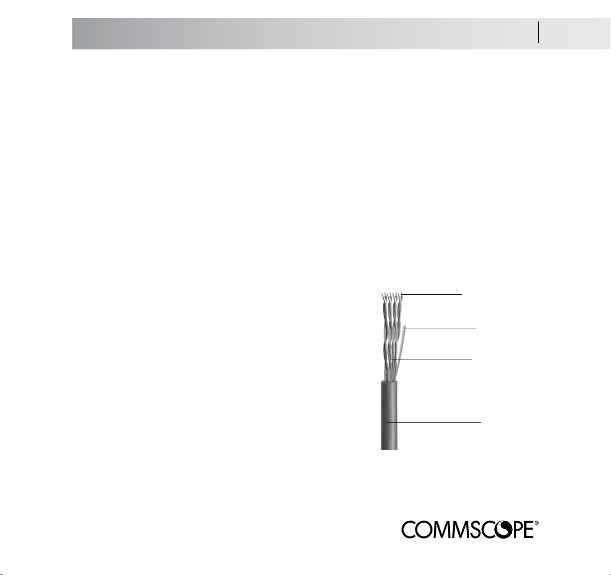
Coaxial Cable Description
Coaxial Drop Cable
The three types of cable used to carry broadband services to and within business and residences are coaxial, fiber
optic and unshielded twisted pair (UTP). Coaxial (or coax) cable is the most common; it is the ‘cable’ in the term
‘cable TV.’ The vast majority of broadband networks are constructed using some type of coaxial cable. Coax is
made up of these basic components:
The center conductor carries a low-voltage RF or electronic digital signal and may also carry up to 150 volts
of power (see Safety Standards, Section 13.3). For optimum strength and performance, CommScope uses copperclad steel for our coax - other types (solid copper, silver coated copper clad steel) are available;
The dielectric is a polymer insulation that supports the conductor. CommScope enhances the performance of its
coax by using foamed (or cellular) dielectrics that offer lower loss;
The shield defends the signal from RF interference. CommScope
uses a foil/aluminum wire braid combination for long-term protection and performance; our highest performance QR
®
320 cables use
a welded and bonded .013 in (0.3 mm) thick strip of aluminum as
a shield. Shielding corrosion can be prevented with CommScope’s
BrightWire
Heal
®
treatment, and a braid shield impregnated with Migra-
®
flooding compound will resist moisture migration;
The jacket protects the entire assembly. Jacketing materials will vary
depending on the application - tough polyethylene (PE) is used for buried installations; lower smoke-and-flame producing polyvinyl chloride
(PVC) is used aerially and indoors, as are plenum-rated fluorinated
ethylene propylene (FEP) and polyvinylidene fluoride (PVDF).
For aerial installations, a messenger wire is built into the cable for
support. CommScope also offers Multi-Reach
®
cables that add up to
six voice-grade UTPs for discrete phone service or powering.
copper-covered
steel conductor
foamed dielectric
foil/braid shield
combination
messenger wire
jacket
Page 8
2.2 Cable Descriptions
The Importance of Braid Shielding
Braid Shielding and Coaxial Cable Performance
A coaxial cable must have, at minimum, a dual shield of aluminum foil tape overlaid with a woven braid of aluminum. This braid shield greatly improves the electrical and mechanical performance of the coax;
in fact, a braid shield can vastly increase the installed life of the cable. All CommScope subscriber access coaxial
cables use a combination of foil and braid shields.
Braid Shielding Provides Low Frequency Protection
Foil shielding is usually a layer of aluminum bonded to a polyester tape. It provides
100% coverage over the dielectric and is best at preventing ingress and leakage of
high frequency signals; however, it is not that effective with lower frequency signals.
Aluminum braid shielding complements foil by containing and preventing interference
from those lower frequencies.
Braid shields
increase cable
performance
and can
greatly extend
the useful life
of the cable
Braid Shielding Helps Maintain DC Resistance
Foil shielding is very flexible but lacking in mechanical strength. Stress caused by installation or by twisting and
flexing over time (like in an aerial installation) will cause microscopic gaps to open in the foil. These ‘microcracks’
degrade the electrical integrity of the foil and cause the DC resistance of the cable to rise. Resistivity gets worse as
the cable twists.
Strong, flexible braid shielding supports the foil and helps fight the formation of microcracks. The braid wires do
not microcrack; they bridge the gaps in the foil. Braid shielding keeps its integrity and delivers low and constant
resistivity numbers even when twisting and flexing.
Braid Shielding Keeps Attenuation Low
Attenuation performance goes hand in hand with DC resistivity; high resistivity caused by microcracks in the foil will
result in higher attenuation. A history of 15,000 flexures can degrade a foil shield to the point where the calculated
attenuation could worsen by 400% or more. However, the robust nature of the additional braid shield keeps attenuation low.
Braid Shielding Keeps Connectors Connected
The additional strength provided by braid shielding gives connectors something to hold onto. In terms of pulloff
force, both compression and crimp-fitted connectors hold much tighter to cables with braid shields.
Page 9
Cable Descriptions 2.3
UTP Cable Descriptions
UTP Indoor Cable
Unshielded twisted pair (UTP) cables consist of two insulated conductors twisted together in a very precise fashion;
four of these pairs are then jacketed together into a cable. The angle and number of the twists acts like a shield
and helps the digital signal stay robust over longer distances. UTP is used inside buildings to distribute voice and
data signals over relatively short distances.
Through advances in construction and materials, UTP cables have a much higher bandwidth (information carrying
capacity) than their telephone wire cousins. Most UTP cables are defined by a ‘category’ or a performance designation. The categories are roughly determined by the bandwidth, or information-carrying capacity, of the cable.
Category 5 (a data cable rated at 100 mHz of bandwidth) is the most commonly used type in residences. For
higher data speeds and increased bandwidth, CommScope also offers Ultra II™ enhanced Category 5e (200
mHz) and UltraMedia™ Category 6 (400 mHz) cables.
Maintaining the twist is essential, especially during connectorization - the conductors must remain
twisted right up to where they meet the jack. The loss of just one twist can degrade the performance of the cable so
as to render it useless as a high-speed data cable.
UTP cables consist of three basic components:
solid copper conductors
24 or 23 AWG
The conductor is 23 or 24 AWG solid bare copper;
The insulation is usually a solid PE (foamed for UltraMedia)
with FEP used in plenum cables; and
The jacket is a riser-rated PVC or plenum-rated FEP or PVDF.
Because these cables are used indoors, pay special attention to
the NEC rating of the application.
polyethylene
insulation
4 twisted pair
components
PVC jacket
Page 10
3.1 Cable Selection
Distance of the Drop
Coax Selection Considerations - Distance
Coax cable can be engineered for several levels of performance and cost-efficiency. For instance, a larger cable
will carry a signal over a longer distance; additional shields provide more protection from interference. Your first
consideration, however, is the overall distance of the drop. CommScope offers cables tailored for different distances:
Maximum Attenuation @ 68°F
QR® 320 F11 Series F6 Series
MHz dB/100’ (dB/100m)
5 0.24 (0.79) 0.38 (1.25) 0.58 (1.90)
55 0.84 (2.76) 0.96 ( 3.15) 1.60 (5.25)
83 1.07 (3.51) 1.18 (3.87) 1.95 (6.40)
181 1.60 (5.25) 1.75 (5.74) 2.85 ( 9.35)
211 1.73 (5.68) 1.90 (6.23) 3.05 (10.00)
250 1.86 (6.10) 2.05 (6.72) 3.30 (10.82)
300 2.04 (6.69) 2.25 (7.38) 3.55 (11.64)
350 2.25 (7.38) 2.42 (7.94) 3.85 (12.63)
400 2.38 (7.81) 2.60 (8.53) 4.15 (13.61)
450 2.52 (8.27) 2.75 (9.02) 4.40 (14.43)
500 2.72 (8.92) 2.90 (9.51) 4.66 (15.29)
550 2.85 (9.35) 3.04 ( 9.97) 4.90 (16.08)
600 2.98 ( 9.78) 3.18 (10.43) 5.10 (16.73)
750 3.34 (10.96) 3.65 (11.97) 5.65 (18.54)
865 3.62 (11.88) 3.98 (13.05) 6.10 (20.01)
1000 3.89 (12.76) 4.35 (14.27) 6.55 (21.49)
F6 & F11
(
)
187
lower numbers are better - plenum cables will have higher attenuation
®
QR
320 - these
are our highest
performance coax
and are recommended for MDU
usage (see section
12) or extremely
long runs with
their .071 in (1.80
Ask yourself
three questions:
what’s the
distance,
what’s the
environment
and how
much shielding
is needed?
mm) copper-clad aluminum center conductor.
F11 Series Cables - excellent-performing coaxial cables with a 14 AWG (1.63 mm) copperclad steel center conductor. They are recom-
mended for use in runs of over 150 ft (45
meters).
F6 Series Cables - these are made for shorter
runs, with an 18 AWG (1.02 mm) copper-clad
steel center conductor. They are recommend-
ed for use in runs of 150 ft (45 meters) or
less.
These cables are available in constructions for aerial and buried outdoor installations. They are also available for
residential and commercial indoor (general, riser and plenum) usage.
Page 11

Cable Selection 3.2
Indoor/Outdoor and Shield Selection
Coax Selection Considerations - Shielding and Environment
Once you’ve determined which cable answers your need for signal over distance, you need to determine the type
of cable you’ll need for the installation environment.
For areas of possible RF interference, (pager antennas or other visible
problem as outlined in Section 3.1, or if there is a history of customer comments
concerning interference from ham radios, etc.), consider using a Tri-Shielded cable
(foil/60% braid/foil) shield. The extra layer of foil provides additional protection
against high-frequency RF signals at little additional cost. Super-Shield (Quad) cables
(foil/60% braid/foil/40% braid) provide optimum protection against RF interference.
Tri-shielded
cables offer
excellent RF
protection at
reasonable cost
For aerial installations, select a messengered cable (also called a figure-8 cable) with a polyvinyl chloride
(PVC) jacket. The messenger wire is a steel wire that is webbed together with the coax. This wire supports the coax
- under no circumstances should subscriber access coax be run without a messenger or lashed to a wire.
For buried installations, select a polyethylene-jacketed cable with MigraHeal
moisture ingress in case of damage. Article 830 considerations (see page 13.3 and Buried Installation 6.1) make
the use of cable pre-installed in conduit (CommScope’s ConQuest
®
) very attractive.
®
flooding compound to prevent
For cables that transition from outside to inside (from the ground block to the inside connection), select
a CATV cable for residential use, or select a CATV or CATVR cable for commercial buildings.
For commercial installations, CATVR riser and CATVP plenum cables are required in certain circumstances.
A riser-rated cable may be run vertically between floors; plenum cables are designed for use in air-handling
spaces, such as the area above a hung ceiling. General purpose cables (CATV) may be run horizontally within or
along walls and in raceways - they cannot transition between floors.
For locations where salt or other aerial corrosives may be a problem, CommScope offers two
aerial cable anti-corrosive treatments for braid shields: BrightWire
®
, a dry treatment that chemically combines with
metal components to protect against corrosion (and improve DC loop resistance); and APD (Amorphous Polypropylene Drop), a non-flowing polypropylene flooding compound.
Page 12
3.3 Cable Selection
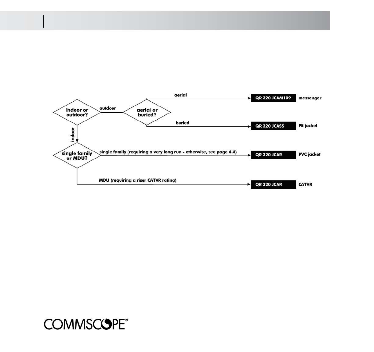
QR® 320 Cable Types
QR® 320 Series Selection Matrix (MDUs and Very Long Runs)
This is a quick reference for QR 320 Series cables from CommScope. Answer the questions as you read along the
diagram to arrive at the construction code for the cable required for your application.
QR 320 cables have a unique welded aluminum strip shield for superior RF protection and a large center conductor for lower attenuation over longer distances. We recommend them for use in MDUs.
Underground QR 320 cables use MigraHeal
®
flooding compound which is applied under the jacket , making it
suitable for direct burial. MigraHeal floodant is designed to flow into damaged jacket areas, sealing this area and
inhibiting corrosion.
Page 13
Cable Selection 3.4
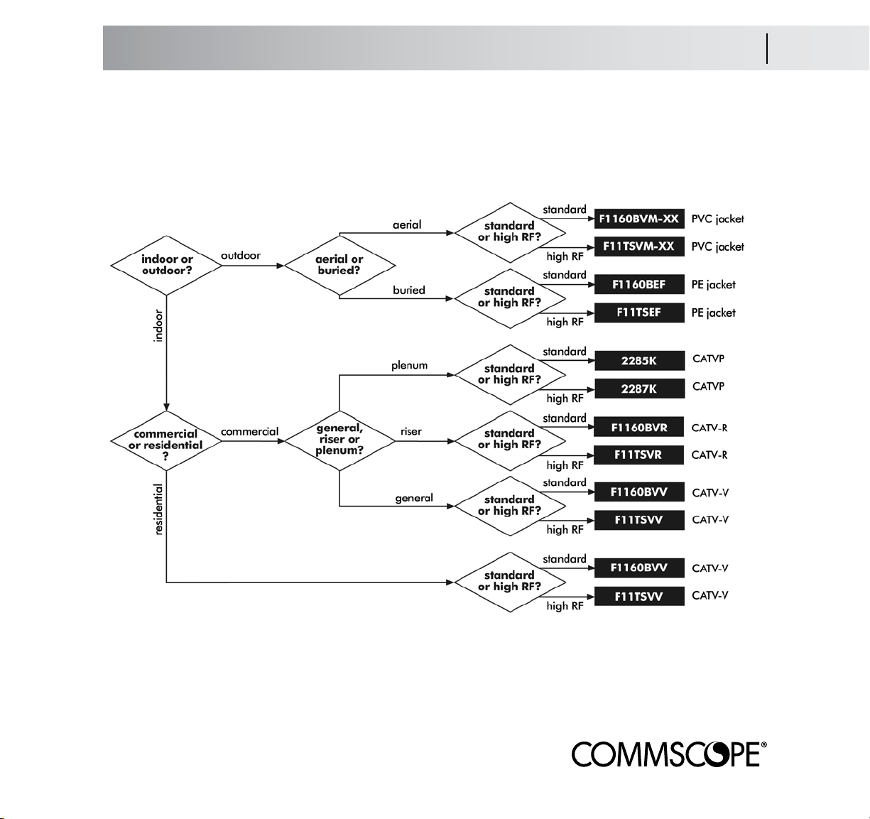
F11 Cable Types
F11 Series Selection Matrix (Runs Over 150 ft/45 Meters)
This is a quick reference for F11 Series cables from CommScope. Answer the questions as you read along the diagram to arrive at the construction code for the cable required for your application:
The XX in the part number should be filled with the code for the anti-corrosion agent you’d prefer as follows: BW
for CommScope’s dry BrightWire
®
, or APD® for the more traditional APD flooding compound.
All non-plenum high RF cables are Tri-Shielded (foil/60% braid/foil); super-shield versions are available. Plenum
cables are available only with super-shields.
Page 14

3.5 Cable Selection
F6 Cable Types
F6 Series Selection Matrix (Runs 150 ft/45 Meters or Less)
This is a quick reference for F6 Series cables from CommScope. Answer the questions as you read along the diagram to arrive at the construction code for the cable required for your application:
The XX in the part number should be filled with the code for the anti-corrosion agent you’d prefer:
BW for CommScope’s dry BrightWire
®
, or APD® for the more traditional APD flooding compound.
All non-plenum high RF cables are Tri-Shielded (foil/60% braid/foil); super-shield versions are available. Plenum
cables are available only with super-shields. A 90% braid is available for 2276K.
Page 15
Cable Selection 3.6
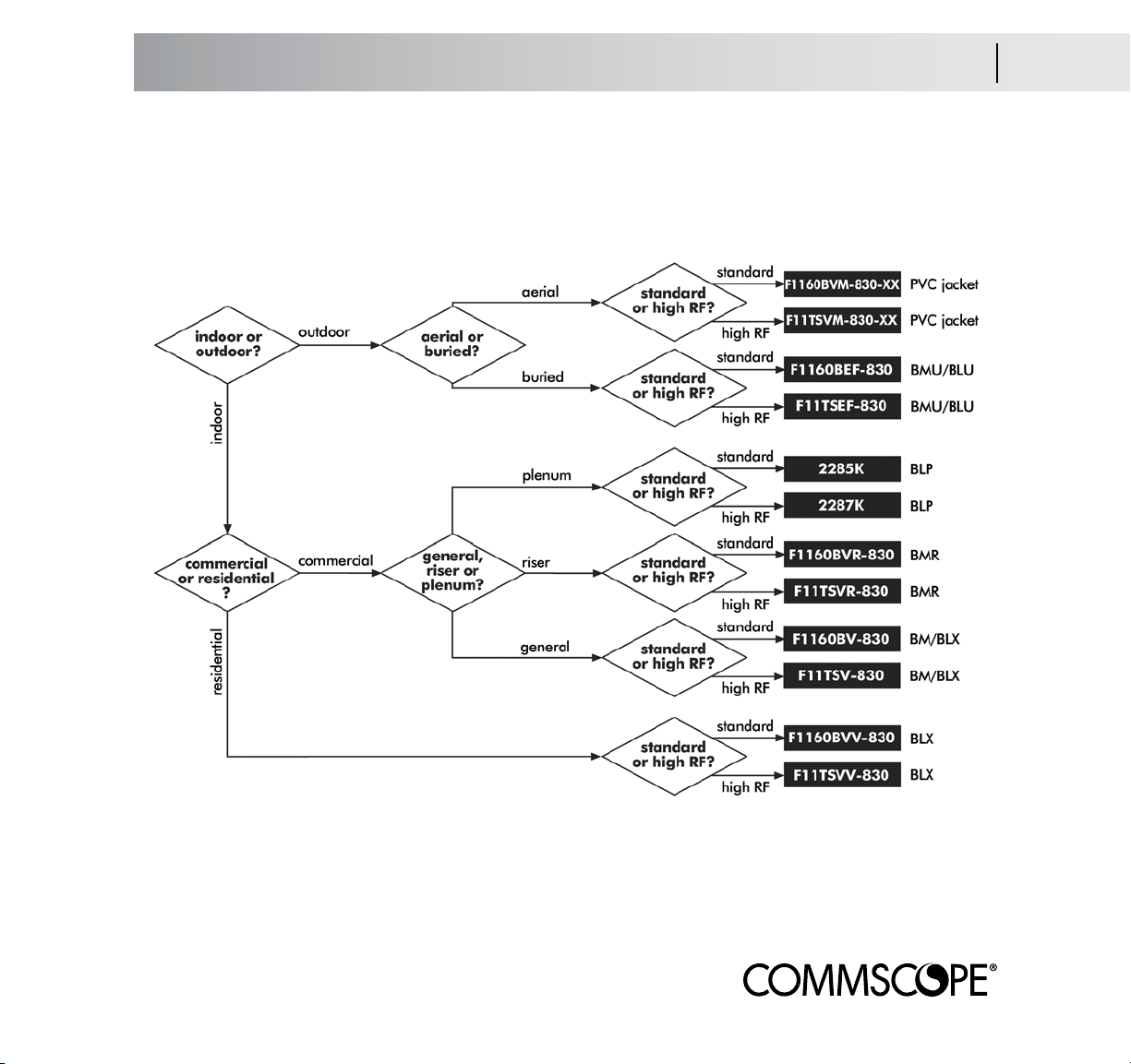
F11 Cable Types for NEC 830
F11 Series Selection Matrix for NEC 830 (Runs Over 150 ft/45 Meters)
This is a quick reference for F11 Series cables that meet NEC 830. Answer the questions as you read along the
diagram to arrive at the construction code for the cable required for your application:
The XX in the part number should be filled with the code for the anti-corrosion agent you’d prefer:
BW for CommScope’s dry BrightWire
®
, or APD® for the more traditional APD flooding compound.
All non-plenum high RF cables are Tri-Shielded (foil/60% braid/foil); super-shield versions are available. Plenum
cables are available only with super-shields.
Page 16
3.7 Cable Selection
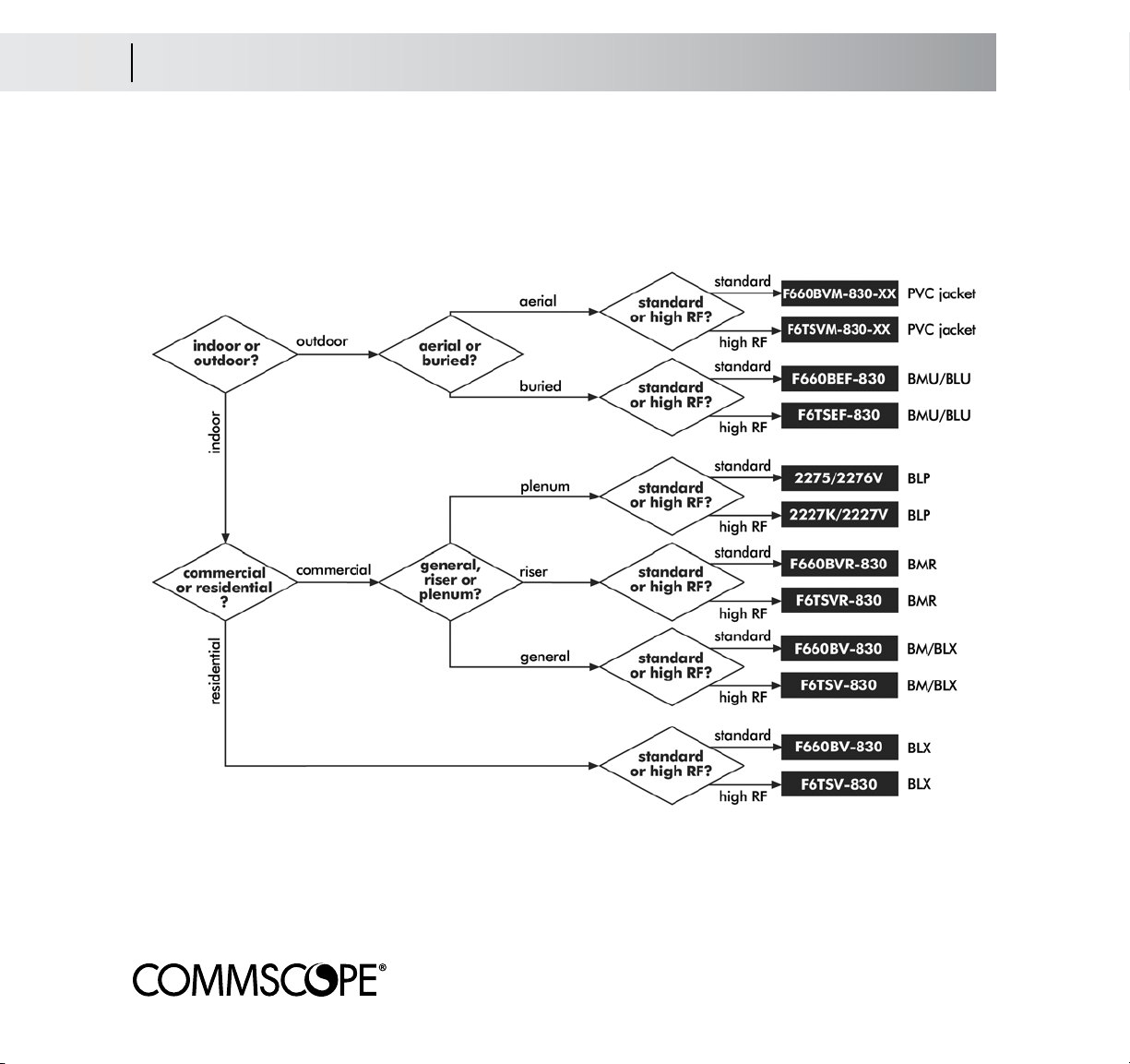
F6 Cable Types foro NEC 830
F6 Series Selection Matrix for NEC 830 (Runs 150 ft/45 Meters or Less)
This is a quick reference for F6 Series cables meeting NEC 830. Answer the questions as you read along the diagram to arrive at the construction code for the cable required for your application:
The XX in the part number should be filled with the code for the anti-corrosion agent you’d prefer:
BW for CommScope’s dry BrightWire
®
, or APD® for the more traditional APD flooding compound.
All non-plenum high RF cables are Tri-Shielded (foil/60% braid/foil); super-shield versions are available. Plenum
cables are available only with super-shields. A 90% braid is available for 2276K.
Page 17
Cable Selection 3.8
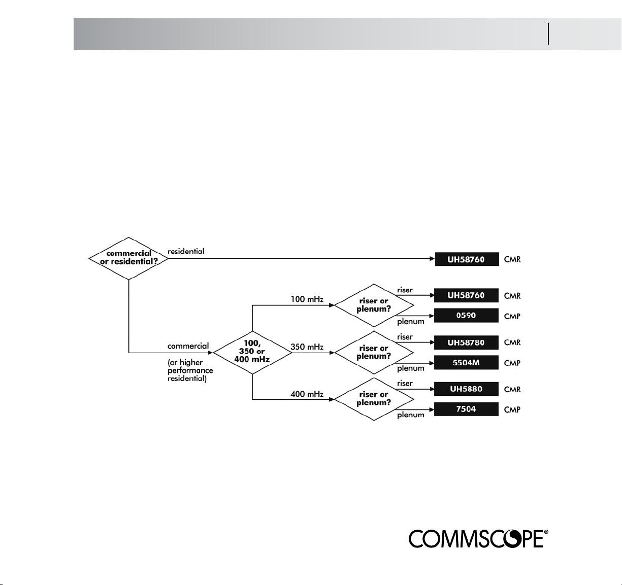
UTP and Fiber Optic Cables
UTP and Fiber Optic Cables
Two factors control the selection for UTP and fiber optic cables; the speed of the network they will support and the
NEC rating required by the installation.
For UTP cables within the home, CommScope’s Category 5e UTP (product code UH58760) offers more
than enough bandwidth for most applications. These cables meet the NEC CMR (riser) designation.
If you are installing UTP in a commercial application (or require higher performance in a residential
application), see the chart below:
For fiber optic cables within the home, we recommend a two-fiber interconnect with a riser rating using
multimode fibers (construction code R-002-IC-6F-FSDOR). A plenum version is available.
Page 18
4.1 Planning the Run
Overview
Planning the Run
The time you take in examining the site prior to installation is well spent and can help you avoid problems later on.
You need to be aware of issues such as right-of-way (ROW), where you will tap into the span, the distance of the
run and where you will attach and bond the cable at the customer’s structure. Refer to Section 3/Cable Selection
to determine what cable to use based on distance or NEC 830 considerations.
Look for Antennas to Select Cable Shielding
A 60% braid/foil shield works for almost all CATV installations. If you are installing
cable intended for a more active, two-way service (internet, high-speed data), you
should consider a Tri-Shielded cable. Cellular and pager towers produce radiation
that tends to raise havoc with CATV channels 19, 20 and 21. Ham radio aerials
may also signify a problem. Urban zones (like southern California or metropolitan
New York) have inherently high levels of RF pollution. We recommend Tri-Shielded
cables with a minimum of 60% braid for areas with high RF concentrations.
Know Your ROW (Right-Of-Way)
The most direct route may not be the legal route. Make sure the route you’re planning runs ONLY over the customer’s property. Generally, you can follow a parallel path to power or phone lines. However, UNDER NO CIRCUMSTANCES lash your drop to any other cable.
Locate the Tap
While most spans have taps located next to the poles, you may occasionally find a tap in mid-span. This may be
helpful in avoiding ROW issues.
Select Your Attachment Point for Ease of Bonding and Access
NEC 820 specifies that coaxial cable must be bonded, preferably with the electrical. Therefore, try to attach the
cable to the wall or corner nearest the meter. If that can’t be reached, an exterior cold water pipe (if the plumbing throughout the building and back to the main is entirely metal) or an existing ground rod will do. If these are
impractical, you will have to hammer in a ground rod. In most cases, you will be selecting the cable entry point
into the building; however, if the NIU is already in place, try to attach your cable as close to it as you can, keeping
bonding considerations in mind.
Whether the
installation is
aerial or buried,
a simple site
survey now
can prevent
headaches later
Page 19

Planning the Run 4.2
Attachment Examples
Attachment Examples for Aerial Installations
The top example shows a pretty
straightforward installation. The electric
meter is on the opposite side of the
building from the span, so attachment
near the the cold water tap is acceptable.
The middle example shows that the
most direct route would trespass on
neighboring property. Therefore, the
drop should be run along the span
and then angle to the building, eventually running toward the meter and then
back to the point of entry. Be sure to
check mid-span; it is possible that there
may be a tap there because a pole
was there at one time.
The bottom example is a tough call.
It’s marginally shorter to attach near
the point of entry, run to the meter for
bonding purposes and double back to
the point of entry.
In all cases, check your local
code requirements and
system design specifications
for your prescribed
bonding requirements.
Page 20
5.1 Aerial Installation
Overview
Aerial Installation/Messenger (Figure-8) Cable
For best efficiency and lowest cost, aerial installation is generally preferred. However, local or subdivision codes
sometimes require that utilities be installed underground. There are times the customer may want the cables hidden
for aesthetic reasons. In these cases, see Section 6 for instructions on buried installations.
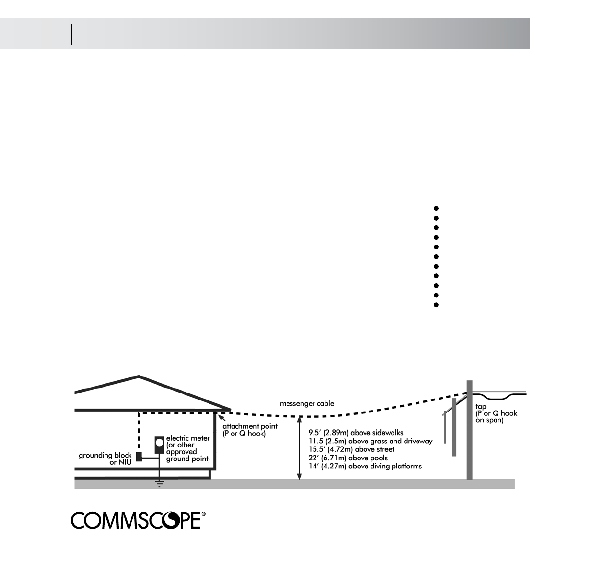
A typical installation is shown below. A continuous length of cable runs from the tap to the attachment point and
continues to the grounding point, called a ground/bond block. A second cable continues from the ground block
through the point of entry to a termination point within the structure.
Article 830 Considerations
Some systems use coaxial or UTP cable to carry power as well as signal to the NIU
(Network Interface Unit - sometimes called a NID/Network Interface Device). When
installing powered coax cable (carrying up to150 volts), pay special attention to the
cable-to-earth distance as shown in the diagram below.
NEC 830 also requires that cable attached to the building within 8 ft (2.5 m) of grade
must be placed within conduit, raceway or some other approved cable guard.
NIUs and Ground Blocks
NEC 830 installations will terminate at an NIU. Most NIUs have built-in connections that must be grounded at the
meter or other approved point. See Section 8/Attaching to the NIU per NEC 830.
tech tip:
when pulling
and hanging
cable, avoid
twisting,
scraping,
stepping on
or crushing it
Page 21

Aerial Installation 5.2
Pulling Cable
Pull the Cable, Separate the Messenger
Set up your cable pack or A-frame beneath the tap. Take the cable end and walk toward the attachment point. Don’t let the cable kink, scrape, tangle or get hung up as
you walk - it may deform the cable and cause transmission problems later.
Keep pulling cable after you reach the attachment point. Remember, you need to have
enough cable in hand to run along the soffit or foundation line of the building to reach
the grounding point.
Go back to the reel and pull enough extra cable to reach the tap. Cut the cable at the reel.
Separate the Messenger From the Coax
Use your side cutters to start a split in the webbing
between the messenger and the coax. Take the messenger in one hand and the coax in the other and
smoothly pull your hands apart to split the webbing.
Pull across the webbing (a scissors pull) instead of
pulling the webbing directly apart.
tech tip:
always pull
more cable
than you
think you’ll
need
Connectorize the Cable
Attach the connector per the instructions on page
9.9/Coax connectorization.
Page 22

5.3 Aerial Installation
Span Attachment
Attach the Messenger to a Drop Clamp
1. Separate the messenger wire from the cable using the 90° (scissor) pull of the messenger and the cable, separating the length of messenger wire needed to make the wrap; about 15 to 18-inches.
Note: Never use the drop clamp, a knife, or other sharp tool to separate messenger & cable.
2. Fit the cable and messenger wire into the drop clamp as
shown, so that the clamp bail is between the two.
3. Pull the messenger wire around the center of the bearing surface as shown, toward the rear or drop-side of the
clamp.
4. Serve the messenger wire through the messenger wire
slots and begin the wrap about the clamp body, as shown.
5. Continue the messenger wire wrap for two full turns.
6. Serve the messenger wire through the bottom messenger wire slot, as shown, to the drop-side of the clamp
and cut the excess wire away, or ground it to the strand.
CommScope does not recommend the use of the 2-4-4
Method or other methods of tying off the messenger
around the cable. Studies have shown that the cable’s
impedance will change and worsen with loading.
Page 23

Aerial Installation 5.4
Connecting the Coax
Connect the Coax to the Tap
The cable should be connectorized per the instructions on page 9.9/Coax connectorization. Some systems like to
protect the connection with a shield (a physical covering to protect against tampering). Place that over the connector now - you will require an F-connector tool to tighten the connection.
With the messenger secured to the span, screw the connectorized cable into the tap hand-tight. Using a torque
wrench, tighten the connector to 30 lbs/in. If you don’t have a torque wrench, twist the connector an extra 1/4
turn with your wrench or F-connector tool to seat it. Cover the connection with a boot.
You should have about 2 ft (60 cm) of cable between the tap and where the cable joins the messenger. Along
with the ease of handling this provides, this extra cable will be very useful if you ever need to re-connectorize the
cable.
Store this cable by forming a loop of about 6 in (15 cm) in diameter. Make sure the diameter of the loop is no
smaller than 10 times the outer diameter of the cable. Use cable ties to form and secure the loop to the span.
Attach an identification tag to the cable.
Page 24

5.5 Aerial Installation
Attaching the Cable to the Residence
Attach the Cable to the Residence
Using a ladder or a lift truck, climb up to the attachment point and screw or drive the P-hook or Q-hook into the
residence. Use an insulated hook if you are bringing in powered service per NEC 830. A good attachment point
is the corner of the house under the soffit. NEVER attach to an antenna, rain gutter, chimney, power mast or lightning rod. The hook should be parallel to the ground.
The attachment point should not be any closer than 4” (10 cm) from a telephone
cable or 1 foot (30 cm) from a power line. Make certain you meet all
clearance requirements.
Taking the cable in hand, climb up to the attachment point. Pull the cable taut until
the sag is 1% of the overall length of the drop (examples: for a 100’ run, the sag
should be 1 foot; for a 50’ run, the sag should be 1/2 foot). Use your hand to
mark the place on the cable where the cable and the hook meet while maintaining proper sag. DO NOT pull the cable through the hook or attach it to the hook.
Select a point on the cable at least 1 foot (30 cm)
beyond where the cable and hook would meet. Using side cutters, cut the messenger wire, being careful not to nick the jacket of the coax. Pull the messenger and
the coax apart to produce over 1 foot (30 cm) of messenger. Shear, don’t tear the
cable (see page 5.2).
Page 25

Aerial Installation 5.6
Running to the Grounding Block
Run the Cable to the Grounding Block or NIU
Using the 2-4-4 method described on page 5.4, attach the messenger wire to the hook (or use a messenger wire
clamp). Strip the remaining messenger wire from the coax.
Route the cable from the attachment point to the grounding block or the entry point for the NIU. The path should
follow the architectural details of the residence, running down at the corners and across at beams and seams in
the siding.
Use cable clips to attach the coax to the house. A variety of screw-in or nail-in clips are available for wood and
masonry. Special snap-in clips are available for vinyl and aluminum siding. Never staple coaxial cable. Stapling will deform the dielectric and may damage the shield; in either case, a loss of performance will result and
you will have to replace the cable.
Place your first clip so as to allow for
a small drip loop. Then place the clips
about every 3 feet (1 meter) for vertical runs and no further apart than 18
inches (.5 meters) on horizontal runs.
Make sure you do not kink or bend
the coaxial cable tighter than the recommended bend diameter (usually
10x its outer diameter - check your
cable specs to be certain). All coax
connections to the grounding block or
splitters must be horizontal.
If connecting to a ground block, proceed to Section 7. If connecting to an
NIU, proceed to Section 8.
For NEC 830,
use an
insulated
hook for
attaching the
messenger
wire
Page 26

6.1 Buried Installation
Overview
Buried Installation
Underground service has become popular in many developments and subdivisions. Broadband services are
brought in by buried cable, and accessed by pedestals which are usually at the property line.
While the easiest way to run the cable is to trench or plow in a burial-grade coaxial cable to a minimum depth of
12 in (.3 m), burying cable preinstalled in conduit is a far better method. Cable-in-conduit (CIC)
offers greater physical protection against environment, abrasion, rocks, etc. than direct burial which can prolong
the life of the cable. And, should the cable ever fail, it can be replaced without digging up the yard. CIC of 1/2
in (13 mm) to 3/4 in (21 mm) is recommended. If you are directly burying cable without using conduit, you
should use an 18 in (45 cm) length of it to protect the cable 6 in (15 cm) below and 12 in (30 cm) above grade
where it emerges next to the residence.
Article 830 Considerations
Systems that use coaxial cable to carry up to 150 volts of power (as well as signal) to a NIU fall under NEC 830
regulations. Pay special attention to the buried cable depth as shown in the diagram below. Note that CIC (HDPE
conduit) doesn’t need to be buried as deeply as direct burial installations.
Although NEC 830 permits the use of metal conduit, CommScope does not recommend its use. Problems with
rust, water migration, and potential damage to the cable jacket due to cutting and scraping during installation
are possible results of using metal conduit. Frozen water will crush cable in a metal conduit, but HDPE conduit
will allow the ice to expand and save the cable.
Page 27

Buried Installation 6.2
Plowoing Overview
Plowing Installation Notes
Direct burial cable and cable-in-conduit (CIC) may be installed by trenching or plowing. When plowing, select a
plow chute with a bend radius no smaller (and preferably larger) than the minimum bend radius of the cable or
CIC you are installing. The chute width should be at least 1/2 inch (1.25 cm) larger in diameter than the cable/
CIC.
At the pedestal, dig a trench deep enough and at least twice the length of the plow blade/chute for the plow
blade to enter it comfortably. A similar trench should be dug near the attachment point at the residence. The
cable/CIC may pay-off from the front of the walk-behind plow or from a stationary reel along the route.
Carefully pull enough cable/CIC through the blade to comfortably allow for connectorization. Once the blade is
completely in the ground, manually feed the cable/CIC into the plow blade.
In the walk-behind plow method, pay the cable/CIC over the top of the reel. Do not use reel brakes. In the stationary reel method, pull the cable/CIC end from the reel to the starting trench. With CIC, make sure both ends
of the conduit are capped.
Page 28

6.3 Buried Installation
Trenching Overview
Trenching Installation Notes
The trench should be dug as straight, level and as rock-free as possible. Avoid tight curves. If there are rapid
grade changes, and you are installing CIC, use back-fill to support the conduit. Taking into account NEC 820
and 830 considerations, dig the trench to correct depth.
Mount the reel so that pay-off is underneath toward the direction of the pull. If using CIC, make sure the conduit
is capped.
Pull enough excess cable to permit easy installation at the attachment point and enough to reach a few feet beyond the pedestal. When in doubt of the exact length, always play out more than you think you will need.
Page 29

Buried Installation 6.4
Placement at the Pedestal
Pedestal Preparation
Plowing
Dig a receiving pit to the depth required by either NEC 820 or 830, depending on your application (between 12
and 18 in (30 and 45 cm) (see page 6.2). The pit should be about 6 in (15 cm) wide and 18 in (45 cm) long and
run in the direction of planned line of the installation. The plow blade should be able to fit easily inside it.
Feed your cable or CIC through the plow blade and run it to the bottom of the pit and up through the pedestal
base. The rule of thumb is to leave at least 10 times the outer diameter of the cable for easy connectorization and
leaving some spare cable for connector replacement. If using CIC, tamp some dirt in as backfill support for the
curve of the conduit.
If you are using CIC, keep the end capped until you’ve initially placed the cable. Use a ratchet shear (such as the
Reed RS#1) to trim off the excess conduit. Fill the conduit end with a watertight sealing foam.
Trenching
If trenching, unreel your cable or conduit as shown on page 6.2.
The only difference is that you will not need a
receiving pit, as you will already have the
trench dug.
Page 30

6.5 Buried Installation
Connecting the Drop
Running the Cable and Connecting the Drop at the Pedestal
Plow to the Residence
If you are plowing in the cable or CIC, make sure you have dug a receiving trench to the attachment point of the
residence. Run the plow along your planned route to the attachment point. Remember that for NEC 830 considerations, cable not in conduit must be buried at a depth of 18 in (45 cm). You may not be able to run the tractor
directly to the attachment point; if not, dig a larger receiving pit.
Trench to the Residence
If you are trenching the installation, dig a trench of correct depth from the pedestal to the attachment point on the
residence (see chart on 6.1).
Connectorize and Attach the Cable
After the cable has been placed, connectorize the cable per the instructions on page 10.9/Coax Connectorization.
Once the cable is connectorized, attach it firmly to the tap. Leave a loop of cable 10 times the outer diameter of
the cable to allow for expansion and to leave extra cable should reconnectorization ever be required. Use the sealing sleeve to protect the connection from moisture.
Attach an identification tag to the cable. This is
especially important if there are multiple taps at the
pedestal. Use a cable tie to secure the lower part of
the cable to the pedestal in order to keep the cable
out of any dirt or water. If you are using conduit,
seal the end of the conduit with either a waterproof
expanding foam or with a duct cap. Once the cable is connected and the connections sealed, close
the pedestal.
Page 31

Buried Installation 6.6
Connecting the Drop
Attach the Cable to the Residence
Plow Installation
Unreel the cable/CIC by hand until you have more than enough to reach the attachment point. Always err on the
side of having too much cable.
If you have installed CIC, determine how much conduit you need to reach the attachment point. Using a ratchet
shear, cut off the excess conduit to reveal the cable. Attach the conduit to the wall by using U-clamps.
If you are not using CIC, use an 18 in (45 cm) piece of HDPE or PVC conduit to protect the cable where it exits
the earth. Place the conduit over the cable and run it down to the trench. Secure the conduit to the wall with Uclamps so that 6 in (15 cm) of cable is below grade and 12 in (30 cm) is above grade. Seal the end of the conduit with either a waterproof expanding foam or with a duct cap.
Some installers favor an enclosure on the wall for the attachment point. If so, run enough conduit so as to touch
the base of the enclosure, connecting the conduit using the enclosure manufacturer’s instructions.
If connecting to a ground block, proceed to Section 7. If connecting to an NIU, proceed to Section 8.
Page 32

7.1 Attaching to the Ground Block per NEC 830
Connecting to the Aerial Drop
Attach the Cable to the Ground Block/Aerial Installation
NEC Article 820 states that the ground block should be attached to the wall as close as possible to the electrical
meter. Both the ground wire and the coaxial cable connections should run horizontally. The grounding wire should
be as straight as possible.
The preferred bonding method is to attach the ground block’s bonding wire to the electrical meter ground wire with a wire not less than 14 AWG in size. For recommendations
regarding ground wires sizes, please refer to the National Electric Code (NEC 820-40)
or your local building code. If bonding the ground block to the meter is not possible,
you may bond to an exterior metal cold water pipe running into the earth. As a last resort, you may drive an 8’ ground rod into the earth and attach the bonding wire to that,
but you will need to ground ALL of the grounds of the residence to that rod.
Special Circumstances for Mobile Homes
Bond mobile homes at the electrical service tap. If there is no service tap, you may bond to the frame of the mobile
home using a wire no smaller that 12 AWG. NEVER bond to the siding of a mobile home.
Connectorize the Cable and Form a Loop
Once the bond is attached, cut the coax so that you have a
sufficient amount to reach the ground block comfortably plus
about another 1’ (30 cm). Connectorize the cable (see page
9.9/Coax connectorization) and attach it to the ground block.
Then form a 6 inch (15 cm) diameter loop and secure it with
a cable tie. This extra cable will be useful if you ever need to
re-connectorize the cable.
tech tip:
test the
bond with
a voltmeter
to ensure it’s
properly
connected
Page 33

Attaching to the Ground Block per NEC 830 7.2
Connecting to the Buried Drop
Run and Attach the Cable to the Ground Block/Buried Installation
NEC Article 820 states that the ground block should be attached to the wall as close as possible to the electrical meter. Both the ground wire and the coaxial cable connections should run horizontally. The grounding wire
should be as straight as possible.
The preferred bonding method is to attach the ground block’s bonding wire to the
electrical meter ground wire with a wire not less than 14 AWG in size. For recommendations regarding ground wires sizes, please refer to the National Electric Code (NEC
820-40) or your local building code. If bonding the ground block to the meter is not
possible, you may bond to an exterior metal cold water pipe running into the earth. As
a last resort, you may drive an 8’ ground rod into the earth and attach the bonding wire
to that, but you will need to ground ALL of the grounds of the residence to that rod.
Special Circumstances for Mobile Homes
Bond mobile homes at the electrical service tap. If there is no service tap, you may bond to the frame of the mobile home using a wire no smaller that 12 AWG. NEVER bond to the siding of a mobile home.
Connectorize the Cable and Form a Loop
Once the ground is attached, cut the coax so that you
have a sufficient amount to reach the ground block comfortably plus about another 1’ (30 cm). Connectorize the
cable (see page 9.9/Coax connectorization.) and attach it
to the ground block, Then form a 6 inch (15 cm) diameter
loop and secure it with a cable tie. This extra cable will be
useful if you ever need to re-connectorize the cable.
tech tip:
test the
ground with
a voltmeter
to ensure it’s
properly
connected
Page 34

8.1 Attaching to the NIU per NEC 830
Attaching to the NIU
Attaching to the NIU - The 8 Foot Rule
NEC Article 830 covers the installation of cable from the tap to the connection of the NIU. NEC 830-rated
cables supply the voltage that powers the NIU. The NIU then distributes the various signals coming in over the
drop (CATV, internet, telephone service, etc.) onto the preferred cable and connections that branch from the NIU
throughout the residence. These interior cables (NEC 820 coax, NEC 800 twisted pair, NEC 770 fiber optic)
carry very low, if any, voltage.
Pages 5.1 (aerial drop installation) and 6.1 (buried drop installation) discuss the distances required for a safe installation of NEC 830 cable and service to the residence.
The 8 Foot Rule
NEC 830 requires that powered broadband cables that are attached to a building within 8 feet (2.5 meters) of
the finished grade must be protected by molding or conduit. If you are using CIC, this requirement is
easily met by extending the conduit from the ground to the entry point.
If you are using direct burial cable without
conduit, you must run the cable in conduit starting 18 in (45 cm) below finished
grade and finishing in contact with the
NIU enclosure.
With an aerial installation, the cable
should be placed in conduit with a J-joint
at the top to prevent water from getting
into the NIU, and then run to the top of
the NIU enclosure.
Page 35

Attaching to the Ground Block per NEC 830 8.2
Connecting to the Buried Drop
Bonding the NIU
Bonding the NIU is similar to bonding a standard coax installation (see Section 7 - Attaching to the ground
block). You should attach the NIU to the wall as closely as possible to the electrical meter. The bonding wire is
attached to a point within the NIU enclosure. Specific bonding points will vary with each make of NIU, so please
consult the manufacturer’s instructions. In all cases, the bonding wire should be as straight as possible and run
horizontally to the attachment point at the meter.
The preferred bonding method is to attach the NIU’s bond to the electrical meter ground wire with a wire not less
than 14 AWG in size. For recommendations regarding ground wires sizes, please refer to the National Electric
Code (NEC 820-40) or your local building code.
If bonding the NIU to the meter is not possible, you may bond to an
exterior metal cold water pipe running into the earth. As a last resort,
you may drive an 8’ ground rod into the earth and attach the bonding
wire to that, but you will need to attach all of the grounds of the residence to that rod.
Connectorize the Cable and Attach it to the NIU
Once the ground is attached, cut the coax so that you have a sufficient
amount to comfortably reach the connection within the NIU plus about
another 1’ (30 cm), similar to the pedestal attachment (see page 6.4).
Connectorize the cable (see page 9.9) and attach it to the NIU. If the
cable is entering from above, form a small drip loop below the connection of the cable and the NIU. This loop will be useful if you have to
reconnectorize the cable in the future.
Page 36

9.1 Residential Interior Cabling
Overview
Overview
By now, the drop has been run to the residence, attached and grounded at either the ground block or the NIU.
How and where you enter the residence depends on the types of service that are going to be provided. If there is
no NIU, you need to proceed from the ground block to the various locations around the residence, splitting the
connections as you go. It may be to your advantage to use a ground block with a splitter so that two coax cables
may be run in different directions. With an NIU, multiple and different cabling types may be used on the output
side. A general rule is that CATV coax may be split, but phone and computer UTP should be home run to the
NIU. Cable modems should be placed at the first split.
Article 830 Considerations
Powered broadband cable MUST be terminated to a grounded location at an NIU (see Section 8/Attaching to
the NIU per NEC 830 for details). Except within the wall or in a conduit like commercial electrical cable, NEC
830 cable may not extend any further than 50 ft (15.2 meters) within a residence.
Use the Crawlspace, Basement or Attic to Run Cable
For the ground floor, plan your installation so that the cable runs through the crawlspace or basement and then
up through the floor or an interior wall to the outlets. For the upper floor, run up to and through the attic and
then down through the walls to outlets.
If the crawlspace or basement present problems,
another option is to run the cable around the outside of the residence. Be sure to use an outdoorrated cable. Try to follow the architectural lines of
the house and run the cable in places where the
foundation meets the bottom of the exterior walls,
or vertically along the corner trim, or under the
soffit. You can bury cable next to the foundation
(keeping in mind the burial depth per NEC 820).
Avoid placing cable in direct sunlight, as that will
accelerate cable aging. Consider a non-metallic
raceway to hide and protect the exterior cable.
Page 37

Residential Interior Cabling 9.2
Planning and Pulling the Cable on the First Floor
Planning the Cable Run/Ground Floor
Outlet locations are dictated by customer requirements - put them where they want them.
Visually inspect every proposed outlet location. Be aware of the locations of electrical
wires, plumbing, HVAC ductwork and other impediments. Use a studfinder to locate studs.
As you plan your drops to specific locations within the residence, work within the interior
walls whenever possible. This way, you avoid installation headaches like trying to push
cable through insulation or around windows.
In the example floor plan, the CATV and phone connections in the kitchen should be run beneath the house, but
can just as easily be reached by running the appropriate cable (coax for CATV and internet, twisted pair from the
NIU for phone and in-home data networks) along the foundation of the residence and entering through the exterior. In this case, the homeowner’s concern for outside appearance should be your concern.
The CATV outlet in the corner of the living room can be reached by an exterior run up to the eaves above the garage door and back down at the corner of the house.
The CATV outlet on the interior
wall is best reached by a home run
back to the NIU through the crawlspace or basement. However, the
coax cable could also be split from
either of the two exterior connections. A splitter has one connection
on the input side and two or more
on the output side to evenly divide
the signal between multiple cables.
tech tip:
shorter
cable runs
produce
clearer
signal
Page 38

9.3 Residential Interior Cabling
Cutting Outlet Holes
Locating and Cutting Outlet Holes
Once outlet locations are determined, cut the holes as required. Carefully check the area for any possible obstructions, such as wall studs, plumbing or electrical wires. Be aware that obstructions like windows or interior
openings like kitchen passthroughs may cause problems with dropping cables from above. Pocket doors are another concern; make sure the planned outlet is outside of their open range. Keep an eye open for creative routes
to hide cable, such as running within closets.
Once you’ve settled on the precise locations, prepare to cut the holes
(1) Mark the Location
A communications outlet consists of the mounting bracket, the feet (which hold the bracket in the wall) and the
faceplate. Using the mounting bracket as the template, trace a cutting pattern on the drywall, making sure there
are no studs behind it. Match the orientation (vertical or horizontal) with the other outlets in the room and make
sure your planned cut is level.
(2) Cut the Opening
Using a drywall knife, utility knife or saw, cut the opening. Do
not install the bracket yet; the metal edges may damage the
cable during pulling and installation.
(3) Run the Cable
Once the cable has been run, you may install the bracket and
terminate the cable (see page 9.12/Trim out and finish).
Other Wall Surfaces
Older homes may have plaster and lathe walls that will require
a small rotary saw, or a cutout tool to cleanly penetrate and cut. Masonry walls will require a surface-mounted
box screwed into the brick and a cable raceway to hide the cable.
Page 39

Residential Interior Cabling 9.4
Going Through an Exterior Wall
Going Through an Exterior Wall
Survey the interior of the residence for the outlet location. Using a point of reference that is common to both the
inside and the outside (such as the lower corner of a window pane), measure the vertical and horizontal distances
to the center of the outlet location (example: 1.5 feet over and 1 foot down from the lower corner of the window).
Check again for obvious interference from electrical outlets, wall studs, plumbing,
etc. You may want to shut off any nearby electrical circuit, as acciden-
tal contact with live service may result in a fatal shock.
From the outside, measure from the reference point and drill a thin pilot hole
at a slight upward angle to prevent water from later seeping in through the
hole. If you are going through masonry, use a masonry bit and drill through the
mortar, not the brick. If the pilot hole checks out, enlarge the hole with a larger bit.
Insert a feed-thru bushing.
On the inside, cut the outlet opening in the drywall. Do not install
the bracket yet; the metal edges may damage the cable during
installation.
use electrical
outlet boxes to
tech tip:
help find
wall studs;
they are
attached to
them
Set your A-frame or cable box at the ground block/NIU and pull
the cable with you to the entry point. Allow extra cable for running
through the wall as well as forming a 5 in (13 cm) drip loop. Use
cable clips to attach the cable to the foundation of the residence.
Pass the cable through the bushing and through the hole in the
drywall. Allow plenty of cable for termination. Form the drip loop
and place your last fastener. Seal the bushing with RTV silicone or
a similar weatherproof sealant.
Page 40

9.5 Residential Interior Cabling
Walls from Below
Crawlspace and Basement
Prior to entering a crawlspace or an unfinished basement, look and make sure that your planned entry point is
not blocked by plumbing or unexpected obstructions like spoil left during construction. It may be possible to bring
the cable through the crawlspace entrance. If not, use a masonry bit to drill through the foundation. Insert a feedthru bushing and pull the cable through; allow plenty of extra cable for reaching the outlet on the main floor.
In a finished basement, plan your point of entry as close to the ceiling as
possible and drill from the inside. Place your feed-thru bushing and run the
cable to the inside. With a hung ceiling, you may be able to run the cable
on top of that, attaching the cable to floor joists. Otherwise, run the cable
around the top edge of the room, and then cross to your ceiling entry parallel to the walls. Wire mold can be used to hide the cable.
when drilling, use
the sharp, stiff wire
used to hold floor
insulation in place
tech tip:
or a piece of
coathanger -
Finding the Wall From Below
At the outlet location, trace and cut your outlet hole. Then use a stiff, sharp
piece of wire to drill a pilot hole right at the base of the toe molding (to
leave no sign of a pilot hole at all, remove the toe molding and drill from the base of the remaining molding or
the drywall). When you feel you’ve broken through the floor, detach the wire from the drill and leave it
in the floor.
Go under the floor and locate the wire. Measure
in about 1 in (2.5 cm) (more if you drilled in at a
very steep angle) and, using a thin bit, drill a pilot
hole straight up to make sure you’re in the wall. Enlarge the hole to accommodate the cable and pull
through enough for easy connectorization.
Use cable clips to attach cable to the floor joists.
a drill bit will
tear up carpet
Page 41

Residential Interior Cabling 9.6
Planning and Pulling the Cable on the Upper Floor
Planning the Cable Run/Upper Floor
Visually inspect the outlet locations for electrical wires, plumbing, HVAC ductwork, windows and other impediments. Use the interior walls whenever possible. This way, you avoid installation headaches like trying to push
cable through insulation or around windows, or reaching under a roofline with a drill.
In the example below, all of the outlets can be reached from the attic. The phone outlet in the home office can
also be reached from the exterior by running a cable up to the eaves and then across and down to the outlet location (consider a coax/UTP combination cable for this location). For the interior CATV outlets, a home run back
to the NIU is preferred, but the CATV line can be split and continued.
Run the shortest distance possible, but avoid aisles and areas used for storage. You may need to run around the
eaves, or even clip cable along the inside of the roof and come down a pillar.
The attic is usually accessed from outside by running the cable up the corner of an exterior wall. Before you drill,
inspect the attic and check for any obstructions or clutter. Running cable up from the crawlspace or basement is
a better and far less obtrusive method of getting to the attic. There may be an existing chase, but you may need
to ‘fish’ the cable up and alongside plumbing or HVAC ducting. See page 9.7 for
instructions.
If entering from the outside, drill your entry
hole at the roofline or slightly above it at
a slightly upward angle. Use a feed-thru
bushing to prep the hole (see page 9.4 for
details). Feed the cable through the bushing
and over to the drop; take more cable than
you’ll need. Remember to seal the bushing
after the cable is pulled into place.
Page 42

9.7 Residential Interior Cabling
Fishing Cable into Place
Using Fish Tape to Run Cable
Once cable is run to the attic, it can be fished through interior walls to the outlet location. Fishing cable usually
requires two people; one at the top to feed the fish tape and a helper to receive the tape. A pair of walkie-talkies
is a big help during this process. Use a non-metallic fish tape to avoid electrical shock.
Locate the Drop Point
The top of the walls should be visible under the beams in the attic. You can locate the studs by looking for the
nailheads on the cap, or top board, of the wall. Measuring from a common point, such as the exterior wall, will
give you an approximate reference point. Drill through the wall cap.
1) Fish the Tape
Cut the opening for the outlet as in page 9.3. Run the fish tape through the hole and into the wall. The helper
below should be able to hear the tape slide down the wall. It may be that you have entered the wrong wall cavity.
If so, drill a new hole in the proper location. Once the tape has reached the outlet hole, have the helper tape a
pull string to the tape. Retrieve the tape and the string.
2) Attach the Cable to the String
Tie the pull string to the fish tape, then use several turns
of electrician’s tape to secure about 6 in (15 cm) of cable
to the string. For easier pulling, build the tape up into a
shape with tapered end.
3) Pull the Cable Down
While feeding the cable through the wall, have the helper
gently but firmly pull the cable down to the outlet. If the
cable snags, pull the cable back up and try again. Once
the cable is at the outlet, untape it from the pull string and
draw enough cable to make a connection.
Page 43

Residential Interior Cabling 9.8
Hiding the Cable
Hiding Cable
It is not always possible to run a cable to its planned location within the wall. If the locations cannot be changed,
there are alternate methods of running and hiding cables.
Under the Wallboard
Many houses have a gap at the bottom of the wall that is covered by the floor molding. This gap is usually wide
enough to provide a hidden cable path around a room.
Floor molding usually consists of a toe molding and a baseboard. Both must be very gradually removed in sections. Toe molding is usually nailed in at an angle, so loosen it gently, prying about 18 in (50 cm) apart, both up
from the floor and out from the wall. Place a cloth behind your prying tool so as not to damage the floor or wall.
Baseboards are usually nailed straight in to the wall studs. Gently pry them a very small bit at a time away from
the wall so as to evenly remove the entire board.
Cable can now be run in the gap between the drywall and the floor. When you
get to the outlet location, use a drywall
knife to carve a vertical channel wide
enough for the cable and about 2 in (5
cm) in height. Make sure the molding is
tall enough to cover the channel. Use a
drill to enter the wall and pull the cable
up to the outlet hole.
Using Raceway
Cable entering from the floor can be
clipped to the wall and hidden with a
covering molding. There are several commercial brands of raceway; some are
nailed on, some are glued, some are selfadhesive. Consult the individual manufacturer for installation instructions.
Page 44

9.9 Residential Interior Cabling
Coax Connectorization
Connectorizing Braid-Shielded Coax Cable
These instructions refer to general practices. Exact instructions may vary with
the maker of the tools and connectors you are using. Always refer to the
manufacturer’s specifications.
If you are going to use a boot to protect the connection at the
tap, or if you are using a compression fitting with an independent sleeve, slide it over the cable end first. Strip the end of the coax cable by clamping your cable
prep tool around the cable, making sure that the end of the cable is flush against the stop. Rotate the tool 3x
clockwise, then 2x counterclockwise until you’ve achieved a clean cut.
A clean cut will have a square
end and the cable will have
a round cross-section. The
dimensions in the drawing are
approximate; always check
with your connector manufacturer for exact dimensions.
If you are using a crimp-style or one piece compression connector, slide it over the cable end and use the crimping
tool to firmly attach the connector. A good connection will have
solid contact between the neck of the connector and the braid
under it. The conductor should
extend no more than 1/8 in (3
mm) beyond the front edge of the
connector.
If you are using a two-piece compression connector,
slide the main boot over the cable. Then slide the compression
sleeve up to the back of the connector. Use the proper compression tool to compress the connector to the manufacturer’s specifications.
Carefully bend
the braid back
over the jacket.
On tri- and
super-shield cables, there is an outer
layer of tape; carefully trim that away.
tech tip:
use a braid brush to
brush back the braid.
It makes connector
insertion easier
Page 45

Residential Interior Cabling 9.10
QR
®
320 Connectorization
Connectorizing QR® 320 Solid Shielded Cable
QR 320 cables have a solid aluminum shield instead of a braid/foil shield combination. The dielectric needs to
be cored out by the use of special tools. While the process is described below, you may wish to contact
CommScope Digital Broadband Resource Center (866-333-3272) for more information.
A QR 320 coring tool, a file, a center conductor cleaning tool, wrenches sized for the connectors (adjustable
wrenches are fine) and cable cutters are required. A hi-torque, low-speed drill or a ratchet are optional, but will
speed the process. Wearing safety glasses and gloves is recommended.
Prepare the cable by using the cable cutters to trim the cable to a smooth, round end.
Remove the proper amount of shield and dielectric with the QR 320 coring tool. Slide the cable into
the tool until it stops. With slight forward pressure, twist the coring tool (either by hand or mechanically with the
ratchet or drill) so that the blade begins to strip and core the cable. Continue to turn the coring tool until it spins
freely - the tool has a preset stop that requires no adjustment. Clean the dielectric and shield residue from the
tool.
Clean the center conductor by using a non-metallic cleaning tool. Score the coating on the center conductor at the shield and scrape it toward the end of the conductor. The conductor is clean if the copper is bright and
shiny. DO NOT USE A KNIFE or other metal tool as it may damage the copper cladding.
Remove the correct amount of jacket with the QR 320 jacket removing tool. Slide the cable into the tool
until the cable stops. Turn the tool clockwise to strip the jacket. Continue turning until it spins freely - the tool has
a preset stop that requires no adjustment.Remove any MigraHeal
®
compound that may be on the shield.
Slide the shrink tubing over the cable end, then attach the connector according to the
manufacturer’s instructions. Place and shrink the boot. NOTE: IF YOU ARE USING A HEAT-SHRINK BOOT
(WHICH IS HIGHLY RECOMMENDED), APPLY THE FLAME CAREFULLY. Overuse of the torch may melt the
jacket and dielectric.
Page 46

9.11 Residential Interior Cabling
Connectorization
Connectorizing UTP and Telephone Cable
These instructions refer to general practices. Exact instructions may vary with the maker of the tools and connectors you are using. Always refer to the manufacturer’s specifications.
UTP - the Twist is Important
Twisted pair cable twins its pairs together in a very precise lay, or frequency of twist. This lay provides a shielding
effect that permits high-speed data signals to travel reasonably long distances with minimum interference. Maintaining that twist is essential to top performance, especially at the connector.
The majority of UTP data connectors are of the Insulation Displacement Connector (IDC) type in an RJ45 size
(eight wire). As the wires are crimped into place, the insulation is automatically stripped away to permit clean conductor contact. Other proprietary tools and methods exist; consult your connector maker.
Use a ring tool to remove about 3 in (7.5 cm) of jacketing. Electrician’s snips can be used as long as you are
careful not to nick or cut the insulation. This should expose four twisted pairs color-coded as pair 1/blue, pair
2/orange, pair 3/green and pair 4/brown. When preparing the conductors for connectorization, do
not untwist any more than 1/2 in (1.3 cm) of the pair.
The two most popular UTP wiring schemes
are TIA 568A and TIA 568B. It doesn’t matter which you choose as long as you are
consistent throughout the installation. Place
the conductors in the appropriate slots in
the jack or the outlet (striped conductors in
the odd slots, solid in the even) and crimp
them into place with the appropriate crimping tool.
Phone Wire
Follow the same rules as UTP; instead use a standard 4-wire RJ11 jack. The color of the conductors going across
are 1/yellow, 2/green, 3/red and 4/black.
Page 47

Residential Interior Cabling 9.12
Trim-out and Finish
Trim-Out and Finish
With the cable run to the outlet, you can now trim out the installation.
1) Insert the Bracket
Most brackets are meant to install directly to the drywall. Place the cable through the bracket and insert the bracket in the wall. Insert the ‘feet’ at the bottom of the bracket so as to trap the drywall and the bracket. Tighten the
attachment screw until the foot is firmly set. Repeat this process with the upper foot.
2) Attach the Cable to the Faceplate
Outlet faceplates will vary according to the cable type:
Coax faceplates require that you terminate the cable with a connector and then screw that connector to the female connection on the faceplate. To prevent cable twisting, turn the faceplate when attaching it to the connector,
or just make sure that you are turning only the hex nut of the connector and not the connector itself.
UTP data faceplates require you to connectorize the cable to the jack. This is usually a separate component
that snaps into the faceplate. Connectorize the cable like you did the jack on page 9.11, making sure you follow
the same TIA568 pattern at all locations.
Telephone jacks usually require you to strip back the insulation and screw the wires into marked locations on the back
of the faceplate.
3) Trim Out the Hole
Once the cable is connectorized and attached, carefully
place the excess cable into the hole, making sure that you
do not exceed the bend radius or crimp the cable in any
way.
Page 48

10.1 Multiple Dwelling Units (MDUs)
Overview
Overview
Multiple Dwelling Units (MDUs) have a more strict set of rules for cable installation than single family residences.
Service is dropped from the tap to the building like a residential installation, either aerially (see Section 6) or underground (see Section 7). However, the cable is usually run to some sort of interconnect box which allows the
service provider to secure the connection and prevent tampering. This box may be inside or outside the building.
A building with two or more apartments or condominiums is not considered to be a
single-family residence and is governed by commercial building and safety regulations.
For instance, you may need to use riser-rated cables instead of CATV rated residential
cables. A general rule of thumb is if the cable penetrates the floor (if it runs vertically
between floors), then you must use a riser-rated cble (CATVR for coax, CMR for UTP,
OFNR for fiber). The riser cable is then run horizontally to the outlet (while you may use
a lower rated cable for horizontal runs, the extra time and cost of termination outweighs
the cost difference between the cables). You may use CATV cable inside metal conduit to
pass between floors, though using a riser-rated cable is much easier.
Signal Amplification
Another issue to consider is amplification. The signal being carried by the drop could be split literally dozens of
times, thus decreasing its strength to the point where it is no longer viable. This is solved by installing a line amplifier before the crossconnection. While most amplifiers are powered by the voltage in the cable, some require connection to 110/120V power. Consult the directions from the manufacturer for specific powering instructions.
The run from the crossconnect to the apartment could be several hundred feet. You may wish to consider upgrading your cable (example: from F11 to QR 320) or installing another line amplifier along the route.
Article 830 Considerations
The same rules apply concerning aerial distances (page 5.1), burial depth (page 6.1) and use of raceway or
conduit within 8 ft (2.5 m) of the ground as residential installation. Article 830 also permits you to transition up to
50 ft (15.2) meters of cable to meet an interior-mounted NIU. Longer runs require that the cable be run in metal
conduit or within the wall like electrical wiring.
tech tip:
review
section 9
for complete
advice on
running
cables inside
a structure
Page 49

Multiple Dwelling Units (MDUs) 10.2
Planning and Pulling the Cable
Planning the Cable Run in the Apartment
Customer needs dictate where the outlets are located. Visually inspect every proposed outlet location. Be aware
of potential problems like electrical outlets or HVAC ducting. You may not have the ability to drop cable from an
attic or run up from a crawlspace, so your routing options may be limited. The preferred method would be to follow telecommunication conduit (if it exists) into the building. If not, consider the options shown below.
From the Outside
In the example floor plan, there are two ways to bring the cable in. The solid line shows running the cable from
the exterior, entering the wall and running to the two locations. A suggested routing would be to bring the outdoor cable in at the ceiling line, run the cable along the top of the wall and split it there. Use methods described
on page 9.4 to position the entry point correctly. You can run non-rated cables a maximum of 50 feet (15 meters)
into an MDU; any further distance requires a CATV-rated cable. A CATV-rated cable is then either fished through
or attached to the wall and concealed with wiremold to reach the outlet location. See Section 9 for specifics. The
cable then continues along the top of the wall, over the door and through the interior wall to the second outlet,
where it is either fished or attached to the wall and
hidden with wiremold.
From the Inside
The dotted line shows a possible route from an interior hallway. Cable from a riser is run along the top
of the hall wall and enters the apartment at the ceiling. Use methods described in section 9 to position
the entry point correctly. The cable is split and either
fished through the wall or attached to the outside of
the wall. The cable continues along the top of the
wall, over the door and around to the second outlet,
where it is fished or run down to the outlet location.
Page 50

10.3 Multiple Dwelling Units (MDUs)
One and Two Story Buildings
One and Two Story MDUs
For one or two story buildings, follow the same guidelines for running your cable as Section 9. A visual inspection
of all proposed cable outlets is strongly recommended and will help you plan the best route for the cable.
Use the Crawlspace, Basement or Attic to Run Cable
For the ground floor, plan your installation so that the cable runs through the crawlspace or basement and then
up through the floor or an interior wall to the outlets. For the upper floor, run up to and through the attic and
then down through the walls to outlets.
If the crawlspace or basement present problems, another option is to run the cable around the outside of the residence. Be sure to use an outdoor-rated cable. Try to follow the architectural lines of the house and run the cable
in places like where the foundation meets the bottom of the exterior walls, or vertically along the corner trim, or
under the soffit. You can even bury cable next to the foundation (keeping in mind the burial depth per NEC 820).
Avoid placing cable in direct sunlight, as that will accelerate cable aging. Consider a non-metallic raceway to
hide and protect the exterior cable.
In this example, Apartment #1 is reached
from the outside, running along the foundation and then upward to enter the wall.
Apartment #2 is reached through the basement. Apartment #3 is reached through
the attic. Apartment #4 is reached from
the outside, with cable for #4 running up
an architectural feature on the exterior wall.
Riser-rated cable is being used for
Apartments 2 and 3 since a floor is
being penetrated.
Page 51

Multiple Dwelling Units (MDUs) 10.4
Taller Buildings Outside
Multiple Story MDUs/Riser Installation
Multiple apartments, multiple floors, and the extra distances involved all contribute to the complexity of an MDU
installation. A helper is mandatory. A system designer will be required to specify whether and where line amplifiers
are needed. As always, make a thorough visual inspection of the proposed route and all outlet locations. It may
be that exterior installation is the only option; if so, see page 10.5.
Reaching the Crossconnect
The drop should be grounded outside like a residential installation (see section 7/Attaching to the ground block).
From here, a cable may be run to an exterior crossconnect or enter the building and attach to an internal crossconnect that could be within a wiring or telecommunications closet. If you are using a powered cable (NEC 830)
you may run 50 feet (15 meters) into the building without using conduit; any longer distance requires the use of
metal conduit or placing cable within the wall.
Dropping Cable to the Closet
Check with the maintenance personnel of the building to locate any chases,
risers, ductwork or conduit being used by electrical wiring. DO NOT place
coax cable in the same conduit as electrical cable (unless it is a divided
conduit). In a riser, coax cable must be run at least 12 inches (30 cm) from
electrical wiring. Sometimes, elevator shafts can be used. The important
thing is to use 1) riser-rated cable and 2) a cable with the performance
required to carry the signal over the distance from closet to outlet. It could
be that you will need a higher performance cable for the interior installation than you used for the drop because of the longer internal installation
distance.
Set your cable reel or box near the riser entry point for the floor. Feed the
cable down to a helper at the base of the riser. A congested telecommunications riser may require you to use fish tape to run the cable. See page
9.7 for specifics on using fish tape. Remember, you need to drop a cable
for each apartment, so make sure the riser can accommodate the total
number of cables you’ll be using.
Page 52

10.5 Multiple Dwelling Units (MDUs)
Taller Buildings Outside
Multiple Story MDUs/Exterior Installation
It may be simpler to run the cable on the outside of the building up to each floor or each apartment. A separate
cable will be needed for every unit. As always, make a thorough visual inspection of the proposed route and all
outlet locations.
Prior to installing the cable, read page 9.4 for the methods needed to locate and drill your entry hole.
Running Cable to Each Unit
Use a ladder of greater height than required or a bucket truck to run the cable up the side of the building. Look
for vertical and horizontal architectural elements that will help disguise the installation. Be sure you are using an
outdoor-rated cable.
Take the cable end with you up to the entry point.
Form more cable that you will need (you can never
use too much) into a loose loop. Tie off the loop with
a cable tie and attach the cable to the building wall
with a cable clip. Don’t let the loop hang free until
you have at least two clips in the wall.
Continue to attach the cable to the wall using clips
every 3 feet (1 meter) until you reach the point where
you want to turn downward. Being careful not to exceed the bend radius, attach the cable to the wall as
you descend.
Return to the entry point and enter the wall as described on page 9.4. Untie the cable loop and feed
the cable through the hole.
Page 53

Multiple Dwelling Units (MDUs) 10.6
Inside the Residence
Multiple Story MDUs/Inside the Building
Unless you are able to share a conduit or routing with telecommunications wiring (you cannot run in the same
conduit as electrical wiring unless the conduit is of the divided type), you may have to use a central hallway as
your route. The challenge is to make the installation as unobtrusive as possible.
Hallway Installation with Raceway
The wall/ceiling joint offers a good route for interior installation. If there is a crown molding, carefully remove it
(see page 9.8 for helpful hints). Starting from the riser, lay out the amount of cable needed to reach the apartment entry point. Calculate the amount of cable you’ll need inside the apartment and double it; this will help prevent coming up short inside and the possible reinstallation of the whole cable length. Cut the cable.
At the riser, drill a hole for the cable to enter the hallway. Bring the cable and run it through the hole into the
hallway and then back to the apartment. Use methods described on page 9.4 to position the entry point correctly.
Use a stud finder to make sure you are drilling into a wall cavity. If possible, fish the cable down to the outlet location. Review Section 9 for details.
Once all the cables have been run, replace the crown molding or use wiremold to cover the cables.
Drop Ceilings/Plenums
Cable can easily be laid on top of a suspended ceiling. However, the ceiling might be used as a plenum space
(used for handling air for HVAC). If that is the case, you MUST either place the cable in metal conduit OR use a
plenum-rated cable. See section 11/Commercial installation for details.
Page 54

11.1 Commercial Installations
Overview
Overview
Commercial installations differ from residential and MDU installations in several ways. Fire safety requirements are
more strict. There may be cable raceways and ladders already in position to aid installation. The cable volume
may be greater.
The general scheme of bonding to an exterior point such as the electrical meter still holds. The cable then will
probably transition inside to a wiring closet with a crossconnect box for distribution within the facility. Depending
on the size of the building, this main closet may connect to subclosets in other parts of the structure, or on different floors. Like MDU installations, you may need to consult a design engineer about using line amplification, or
may wish to upgrade to a longer reach cable such as QR 320.
Wiring Closets
Wiring closets (or telecommunication closets or TCs) can be rather complex. Literally hundreds of communication
cables (phone, UTP, fiber) can be gathered here and interconnected through an array of patch panels and blocks.
For specific instructions on connecting these types of cables, consult BICSI’s excellent volume Residential Network
Cabling published by McGraw-Hill.
Riser and Plenum Cables
Any time a cable penetrates a floor (goes vertically between one or several floors), you must either use a riser-rated cable (CATVR) or install your cable in metal conduit. You can also use the plenum (air-handling) space above
a dropped ceiling to run plenum-rated cables (CATVP) without using conduit. These cables are more flame-retardant and produce less smoke during a fire. Many office cubicle systems have built-in raceways that allow you to
drop cables from the plenum ceiling directly to the desktop.
Article 830 Considerations
The same rules apply concerning aerial distances (page 5.1), burial depth (page 6.1) and use of raceway or
conduit within 8 ft (2.5 m) of the ground as residential installation. Article 830 also permits you to transition up to
50 ft (15.2 meters) of cable to meet an interior-mounted NIU. Longer runs require that the cable be run in metal
conduit or within the wall like electrical wiring.
Page 55

Commercial Installations 11.2
Wiring Schemes
Wiring Schemes
A typical schematic for wiring a commercial installation is shown below. Coax cable transitions from the bonding point into the basement of the building and is attached to a crossconnect, probably in a wiring closet. Taking
advantage of existing raceways and risers, riser-rated coax is pulled down the riser (or through the telecommunications conduit) from the higher floors. There, it is connected to a distribution panel and the horizontal cable runs
are made.
On the third floor, plenum-rated cable is run through the ceiling spaces and dropped to the desktops through
custom raceways. It can also be dropped in the walls to outlets. On the second floor, CATV coax can be used to
run along the walls to outlets. It can be concealed with wiremold. On the first floor, a short run of CATV cable is
run behind the floor molding and carried across the floor, protected by a tread raceway.
Due to the length of the long run to the far end of the building, a high-performance cable such as riser-rated QR
320, is run up and over from the wiring closet and across
the building via raceway or cable ladder. If it is in a metal
conduit, a cable with a lower fire rating may be used. Avoid
using plenum cables for longer runs as they tend to attenuate faster.
®
Page 56

12.1 Drop Cable Descriptions/Specifications
Specifications and Part Numbers
Drop Cable Descriptions
In Section 2, the various types of subscriber access cables were generally discussed. This section details the
differences in the varieties of coaxial cable used outside and inside the residence.
The construction examples given in the previous chapters deal with the most helpful types of coax;
®
QR
320, 11 Series (RG 11) and 6 Series (RG6). Commscope offers other types of coax as well, tuned to
various uses within the residence. The full listing of our offerings includes:
®
QR
320 for longest reach and highest performance applications. The large 0.071 in (1.80 mm) copper-
covered solid aluminum conductor is coupled with a welded aluminum shield for maximum performance;
F11 series, recommended for use in runs of over 150 ft (45 meters), with a 14 AWG/1.63 mm copperclad steel center conductor and a standard foil/60% braid construction. Tri-shield (foil/60% braid/foil) and
Super-Shield (foil/60% braid/foil/40% braid) versions are available;
F6 series, recommended for use in runs of 150 ft (45 meters) or less, with an 18 AWG /1.02 mm copperclad steel center conductor and a standard foil/60% braid construction. A foil/90% braid, Tri-Shield (foil/60%
braid/foil) and Super-Shield (foil/60% braid/foil/40% braid) versions are available;
F59 series, recommended for very short runs, has an 0.032 in (0.81 mm) copper-clad steel center conductor and a standard foil/67% braid construction. A foil/95% braid, Tri-Shield (foil/67% braid/foil) and SuperShield (foil/53% braid/foil/35% braid) versions are available;
For further information on any of these cables, go to our website at www.commscope.com and download
spec sheets, or call us at 1-800-982-1708 (1-828-324-2200 outside the US).
Page 57

Appendix 13.1
Safety Overview
Drop Cable Safety Issues
Construction of a broadband cable system requires a substantial amount of manpower, tools and equipment. Underground and aerial construction will expose the manpower, tools and equipment to hazards, dependent on field
conditions and circumstances.
The Occupational Safety and Health Administration (OSHA) defines a qualified employee as “any worker who by
reason of training and experience has demonstrated his ability to safely perform his duties.” Only a qualified employee should be assigned duties that could cause harm or potential harm to the construction crew, general public,
cable plant, and other utilities.
This manual cannot identify the many hazards that exist in the construction environment, nor can it dictate the caution required with all of the tools, equipment and field conditions. CommScope continues this manual with the assumption that the construction personnel performing the work are qualified employees.
Three sets of national codes and standards apply to the construction of cable systems.
Section 1910.268 of the OSHA Safety and Health Standards applies to work in telecommunications centers and field installations. The National Electric Code (NEC) applies to
building utilization wiring, i.e. inside plant construction. The NEC applies specifically, but
is not limited to, plant that is within or on public and private buildings or other structures.
The National Electric Safety Code (NESC), generally applies to outside plant construction.
The ability
to recognize
and avoid
hazards is
required
of all
Municipal, state, county, and local codes are often applied to the construction of cable
systems or work that involves their respective properties and right-of-ways. Pole Lease
Agreements often stipulate specific practices related to safety.
These codes, regulations, and specified practices should be investigated, interpreted, communicated and observed.
construction
personnel
Page 58

13.2 Appendix
OSHA and NEC Standards
Occupational Safety and Health Administration (OSHA) Standards
OSHA Standards were established in 1970 to help ensure workplace safety. The Standards are federal regulations
that are intended to enable employers and employees to recognize, understand, and control hazards in the workplace. Standards have been established for general industry while some sections of the Standards are dedicated to
specific industries such as telecommunications.
The generally applicable OSHA standards are found in:
Title 29 CFR Parts 1901.1 to 1910.441 General Industry, (OSHA), Order No. 869-019-00111-5
Excavations (OSHA 2226), Order No. 029-01600125-5
Underground Construction (Tunneling) (OSHA 3115)
Stairways and Ladders (OSHA 3124)
Copies of OSHA standards can be obtained from:
Superintendent of Documents
U.S. Government Printing Office
Washington, DC 20402
(202) 783-3238
National Electric Code (NEC) Standards
The NEC typically identifies the construction techniques and materials necessary in building wiring requirements,
i.e., inside plant construction, of fiber optic or coaxial cable systems. The NEC has been developed by the National
Fire Protection Association’s (NFPA’s) National Electric Code committee. Committee members are professionals
from the electrical industry. The NEC addresses safety from fire and electrocution. The NEC has been adopted by
the American National Standards Institute (ANSI).
Copies of NEC standards can be obtained from:
National Fire Protection Association
1 Batterymarch Park/P.O. Box 9146
Quincy, MA 02269-3555
(800) 344-3555
Page 59

Appendix 13.3
NEC and Other Ratings
NEC Articles 820 and 830
NEC articles 820 and 830 both deal with broadband coaxial cable. Traditional coax networks carry a low-voltage
radio frequency (RF) signal. The voltage is so low that it is not considered dangerous. NEC article 820 is written
with fire safety, not voltage, in mind.
However, with the advent of multiple services available over coax systems, the need for powered coax or UTP has
risen. Some of these newer services require that a network interface unit (NIU) be installed at the subscriber’s residence with the NIU being powered via the cable. Generally, if there is a NIU involved, the cable will have to be
rated for NEC 830.
Basically, higher voltage NEC 830 cables need to be installed to provide greater protection
for people than NEC 820 cables. Refer to the charts in Section 4.1/Aerial Installation or 5.1/Buried Installa-
tion for specific distances.
Look for the cable rating on the jacket. The cable ratings are:
Plenum-rated cables, designed for use in plenums, ducts
and air handling spaces, carry the strictest NEC rating.
Riser-rated cables are used in vertical shafts that penetrate
more than one floor.
General purpose-rated cables may be used in locations
other than plenums or risers.
Residential-rated cables are for use in one, two and multifamily dwellings and in raceways.
Buried cables are for use underground alone or in conduit.
This rating only concerns NEC 830 applications.
Page 60

13.4 Appendix
NESC Standards and Construction Grades
National Electric Safety Code (NESC) Standards and Construction Grades
The NESC defines grades of construction on the basis of strength requirements for reasons of safety. Section 24 of
the NESC identifies construction grades B (the highest), C, D and N (the lowest).
Grade D construction typically applies to broadband coaxial cable and fiber optic cable. Construction grades B
or C may be applicable dependent on the situations that exist. If more than one grade of construction applies to
a situation, the higher grade will apply. A qualified engineer should evaluate required construction and dictate the
grade of construction. The strength requirements for the various grades of construction are defined within Section
26 of the NESC.
The NESC typically identifies the construction techniques and materials necessary in outside plant construction of
electric supply or communication cable systems.The NESC is an American National Standard that has been written
by a group of professionals that are concerned about the Standard’s scope and provisions. The NESC has been
adopted by the American National Standards Institute (ANSI). All references to the NESC in this manual are from
the 2002 edition.
Special attention should be given to NESC Table 232-1, Vertical Clearance of Wires, Conductors, and Cables
Above Ground, Roadway, Rail, or Water Surfaces which is reproduced in part on the next page.
Copies of NESC standards can be obtained from:
IEEE Service Center
445 Hoes Lane/P.O. Box 1331
Piscataway, NJ 08855-1331
(800) 678-4333
Page 61

Appendix 13.5
Wire Clearance
NESC Table 232-1/Vertical Clearance of Wires
This chart shows the clearances required for a coaxial cable, isolated communication conductors and cable, messengers and surge-protected wire meeting NESC Rule 230C1, depending on the type of surface it is above. For a
complete listing, please contact the NESC at the address on page 3.4:
Surface
feet (meters)
Railroad tracks
(except electrified railroads using overhead trolley conductors) 23.5 (7.2)
Roads, streets, and other areas subject to truck traffic 15.5 (4.7)
Driveways, parking lots and alleys 15.5 (4.7)
Other land traversed by vehicles,
such as cultivated, grazing, forest, orchard, etc. 15.5 (4.7)
Spaces and ways subject to pedestrians or restricted traffic only 9.5 (2.9)
Water areas not suitable for sailboating or where sailboating is prohibited 14.0 (4.0)
Water areas suitable for sailboating with an unobstructed surface area of:
Less than 20 acres 17.5 (5.3)
Over 20 to 200 acres 25.5 (7.8)
Over 200 to 2000 acres 31.5 (9.6)
Over 2000 acres 37.5 (11.4)
Land adjoining water areas posted for rigging or launching sailboats
with an unobstructed surface area of:
Less than 20 acres 22.5 (6.8)
Over 20 to 200 acres 30.5 (9.3)
Over 200 to 2000 acres 36.5 (11.1)
Over 2000 acres 42.5 (12.9)
Minimum Distance
Page 62

13.6 Appendix
Pole Lease Agreements and Other Codes
Pole Lease Agreements and Other Codes and Regulations
Pole Lease Agreements
Cable system operators often enter into contractual agreements with the owners of utility poles. The pole owners
are municipalities, telephone companies, and power companies. There are often specific safety practices that are
specified in the contract. These safety practices may be more restrictive than other codes and standards. The contractual agreements should be investigated for safety requirements. The requirements should be interpreted, communicated and accordingly observed.
State, Local, and Municipal Codes
State, local and municipal codes may also apply to the construction of the cable system. These codes will vary by location. These codes will have to be identified and applied as required on a location specific basis.
Governing Code or Regulation
The more restrictive code or regulation must always be practiced.
The most
restrictive code
or regulation
is the one
that must
be practiced
Page 63

Broadband Resource CenterTM 14.1
Broadband Resource Center...
Your One Stop Source for Cable Information
Responsive support and literally years of deployment experience make CommScope a unique build-out partner
capable of walking you through broadband logistics each step of the way. To design and maintain high-speed,
complex networks you’ll need advanced levels of expertise. We realize that getting your technical personnel prepared to
ascertain system requirements, understand engineering issues, select and install
cable is not an insignificant hurdle. CommScope’s Broadband Resource Center
exists to help you overcome these obstacles. Our staff has skill sets from the RF,
telephony, optical and Internet worlds. We have a menu of services to help you
develop technical competence and leadership within your own staff.
Building a reliable, future-proof broadband network requires not only the best
technology, but also experience and assistance in deploying that technology.
CommScope’s Broadband Resource Center stands ready to assist you in your
goal – the timely and cost effective deployment of state-of-the-art broadband
services.
Our management and technical staff represents over a century of combined experience in coaxial, fiber optic and
copper cable engineering and deployment. Members of CommScope’s Broadband Resource Center team hold several
patents and have been published in a variety of industry publications.
Active In Your Industry
Our employees are involved in industry trade groups such as
Society of Cable Telecommunications Engineers (SCTE), National
Cable Television Association (NCTA), Women In Cable and
Telecommunications (WICT), Custom Electronics Design and
Installation Association (CEDIA) and Home Builders Association
of America (HBA).
Page 64

TM
Technical Services & Tools
Access to the Broadband Resource Center affords access to the a wide array of services and tools:
On-site Custom Training
Includes courses such as:
•InstallationandSplicing
•Constructionlogistics
•Broadbandconcepts
Call Center Support
Get advice such as:
•Whatproductstoorder
•Howtoplanforconstruction
•Whattoexpectalongtheway
Training Collateral – all available FREE,
just call Customer Service and request!
•Comprehensiveproductcatalogs
•Industrystandardconstructionmanuals
(Now available in English & Spanish!)
•TrainingvideosavailableinDVDformat
(Now available in English & Spanish!)
•Publishedarticles
•Whitepapers
•Internetwebsiteaccesstoallproduct
specification sheets
•Attenuationsliderules
•Specificationassistance/review
•Internationalexperience
•Multilingualservicesavailable
Engineering Services
• Laboratoryanalysis
• Standardscommitteesupport
• Fieldtrialsandtroubleshootingsupport
• Sagandtensionanalysis
For more information about our Broadband Resource Center or for information on products,
please contact us by phone at 1-866-333-3272 or send us an e-mail at brc@commscope.com.
Page 65

Disclaimer
Legal Disclaimer
THIS MANUAL IS PROVIDED FOR GUIDANCE PURPOSES ONLY AND SHOULD NOT BE USED OR IN ANY WAY
RELIED UPON WITHOUT CONSULTATION WITH AND SUPERVISION OF EXPERIENCED CONSTRUCTION
PERSONNEL, ENGINEERS OR NETWORK DESIGN SPECIALISTS. COMMSCOPE MAKES NO REPRESENTATIONS
OR WARRANTIES OF ANY KIND, EXPRESS OR IMPLIED, INCLUDING ANY REPRESENTATION OR WARRANTY
REGARDING THE QUALITY, CONTENT, COMPLETENESS, SUITABILITY, ADEQUACY OR ACCURACY OF THE DATA
CONTAINED HEREIN. COMMSCOPE IS UNDER NO OBLIGATION TO ISSUE ANY UPGRADES OR UPDATES OR
NOTIFY CUSTOMERS/USERS OF THIS MANUAL THAT CHANGES HAVE BEEN MADE TO THIS MANUAL. THE USER
OF THIS MANUAL ASSUMES ALL RISKS ASSOCIATED WITH SUCH USE, AND COMMSCOPE HEREBY DISCLAIMS
ANY AND ALL LIABILITY FOR DAMAGES OF ANY KIND RESULTING FROM SUCH USE.
Page 66

1100CommScopePlaceSE•P.O.Box1729
Hickory,NorthCarolina28603•Tel:1.866.333.3272(3BRC)
brc@commscope.com • www.commscope.com
©2013,CommScopeInc.AllRightsReserved.•CO-107145-EN•08/2013
 Loading...