

Page 1

Broadband Applications
& Construction Manual
BOSTM BrightPath® Optical Solutions
Page 2

Page 3

Table of Contents 0.1
BrightPath® Installation Guide
Table of contents
Section 1 ............... Introduction
Section 2 ............... Safety standards
Section 3 ............... BrightPath cables and components - a system overview
3.1 Direct system overview
3.3 Node-based system overview
3.5 Cables
3.6 Components
Section 4 .............. Before installation
4.1 Moving and storing reels
4.2 Route survey
Section 5 .............. Distribution cable - buried installation
5.1 Overview
5.2 Vibratory plowing
5.4 Trenching for 1000 feet or longer
5.6 Trenching for 1000 feet or less
5.8 Trenching for any distance
Section 6 .............. Distribution cable - aerial installation
6.1 Overview
6.2 Drive-off/moving reel set-up
6.3 Drive-off/moving reel and leaving cable at the pole
6.4 Overlashing
Page 4

0.2 Table of Contents
BrightPath® Installation Guide
Table of contents
Section 7 ................ Optical node installation
7.1 Node description
7.2 Node installation
Section 8 ............... Optical tap installation
8.1 Introduction
8.2 Midspan entry
8.3 Splicing equipment
8.4 Splicing
8.5 Fiber arrangement and testing
Section 9 ............... Drop and NID/NIU installation
9.1 Introduction
9.2 Planning the drop
9.3 Attachment examples
9.4 Attaching and grounding the NID
9.5 Plowing overview
9.6 Trenching overview
9.7 Aerial installation
9.8 Pulling cable and pole attachment
9.9 Attaching the cable to the residence
9.10 Running cable to the NID
Section 10 .............. Connector cleaning and care
Section 11 .............. Broadband Resource Center
Page 5

Table of Contents 1.1
Forward
How to use the BrightPath® Installation Guide
The BrightPath Installation Guide is written for the cable installation professional who is preparing their system to
bring fiber optics over the ‘last mile’ to the subscriber’s residence. The BrightPath Fiber To The Home (FTTH) system
is the next step in CommScope’s Hybrid Fiber Coax (HFC) architecture. With BrightPath, optical fiber (and its associated benefits of speed, capacity and long operational distances) is brought directly to the residence.
BrightPath is a craft-friendly technology. The architecture of nodes, taps and cables should be familiar to coaxial
installation crews. The components have been designed for ease of installation. Techniques used for buried and
aerial installation of coaxial cable are almost identical. And, while easily installed in greenfields, the BrightPath technology can also be adapted to upgrade existing networks.
Of course, the difference between HFC and BrightPath is the use of fiber optic cable for the distribution and drop
segments of the network. Like coaxial termination, fiber optic splicing is a craft. The instructions provided in this
Guide for splicing and termination of optical fibers are general. CommScope strongly recommends that you take a
fiber optic splicing course to familiarize yourself with the tools and technologies.
It is impossible to cover every single situation an installer may run into. These guidelines are no replacement for your
good common sense and experience.
It’s always good to know that you have backup should you run into a difficult installation. If you find you need
advice, call CommScope’s BRC (Broadband Resource Center) at 866-333-3272 from 9 am to
5pm ET Monday through Friday. We’re always glad to help out a fellow professional.
Page 6

2.1 Safety
Overview
Installation safety issues
Construction of a broadband cable system requires a substantial amount of manpower, tools and equipment.
Underground and aerial construction will expose the manpower, tools and equipment to hazards, dependent on field
conditions and circumstances.
The Occupational Safety and Health Administration (OSHA) defines a qualified employee as “any worker who by reason of training and experience has demonstrated his ability to safely perform his duties.” Only a qualified employee
should be assigned duties that could cause harm or potential harm to the construction crew, general public, cable
plant, and other utilities.
This manual cannot identify the many hazards that exist in the construction environment, nor can it dictate the caution
required with all of the tools, equipment and field conditions. CommScope continues this manual with the assumption
that the construction personnel performing the work are qualified employees.
Three sets of national codes and standards apply to the construction of cable systems.
Section 1910.268 of the OSHA Safety and Health Standards applies to work in telecommunications centers and field installations. The National Electric Code (NEC) applies to
building utilization wiring, i.e. inside plant construction. The NEC applies specifically, but
is not limited to, plant that is within or on public and private buildings or other structures.
The National Electric Safety Code (NESC), generally applies to outside plant construction.
The ability
to recognize
and avoid
hazards is
required
of all
Municipal, state, county, and local codes are often applied to the construction of cable
systems or work that involves their respective properties and right-of-ways. Pole Lease
Agreements often stipulate specific practices related to safety.
These codes, regulations, and specified practices should be investigated, interpreted, communicated and observed.
WARNING! Invisible laser radiation may be present on all optical connectors. Confirm that there is
no optical signal present prior to directly viewing any optical fiber or connector.
construction
personnel
Page 7

BrightPath® Cables and Components 3.1
Direct system overview
BrightPath system - direct connection for up to 12.4 miles (20 km)
The BrightPath solution starts at the point where the HFC fiber normally transitions to coaxial distribution cable. If the
distance from the headend to the furthest subscriber is 20 km or less, the BrightPath system can be spliced directly to
the fiber at the transition point. The headend signal is bidirectional, using different wavelengths of light for upstream
and downstream transmission. Each headend fiber can serve as many as 32 subscribers. Please note that the serving capacity of the system is limited by the number of fibers available coming from the headend.
Buried or aerial multi-fiber distribution cables carry optical signal from the transition point to a tap enclosure.
The weather-hardened enclosure protects the optical tap module and is mounted either on the span or in a pedestal. Here, the distribution cable is entered mid-span and its fibers accessed. One fiber is spliced to the optical tap
module that splits the signal among as many as eight drops and then sends the signal on to the next tap enclosure.
Aerial or buried single fiber drop cable connects the optical tap to the Network Interface Device (NID) at
the residence. The NID will hold the Network Interface Unit (NIU) which converts the optical signal to RF for
transmission over the home’s coax network. Low-voltage power for the NIU is provided at the residence and fed
through a coaxial connection.
Page 8

3.2 BrightPath® Cables and Components
Direct system overview
A BrightPath direct system installation typically happens in three phases:
Distribution cable installation and pedestal placement
A cabling crew installs the distribution cable/fiber optic cable in conduit (FOCIC) and places the pedestals.
Splicing the fiber at the tap
A splicing crew follows them and splices the fiber to the headend connection and the taps.
Running the drop and attaching the NID/NIU
As subscribers sign up, drop cable installation crews visit individual homes and attach the NID, run the drop and
terminate it at the NIU.
When directly connected to the headend cable, the BrightPath system requires no external power between the
headend and the final connection to the NIU. And because optical fibers carry no electrical power, NEC article
830 is not a concern.
Page 9

BrightPath® Cables and Components 3.3
Node-based system overview
BrightPath system - node-based connection for up to 21.7 miles (35 km)
The BrightPath node-based solution starts at the point where the HFC fiber normally transitions to coaxial distribution cable. An optical node amplifies the optical signal coming from the headend and distributes it to as many
as eight fiber ports. Each port delivers enough signal to serve 32 homes, for a total of 256 subscribers. The node
signal is bidirectional, using different wavelengths of light for upstream and downstream transmission. The node can
be mounted on the span or in a vault and is powered like a coax amplifier.
Up to two four-fiber buried or aerial distribution cables carry optical signal from the node to a tap enclosure.
The weather-hardened enclosure protects the optical tap module and is mounted either on the span or in a pedestal. Here, the distribution cable is entered mid-span and its fibers accessed. One fiber is spliced to the optical tap
module that splits the signal among as many as eight drops and then sends the signal on to the next tap enclosure.
Aerial or buried single fiber drop cable connects the optical tap to the Network Interface Device (NID) at
the residence. The NID will hold the Network Interface Unit (NIU) which converts the optical signal to RF for
transmission over the home’s coax network. Low-voltage power for the NIU is provided at the residence and fed
through a coaxial connection.
Page 10

3.4 BrightPath® Cables and Components
Node-based system overview
A BrightPath node-based system installation typically happens in three phases:
Distribution cable installation and pedestal placement
A cabling crew installs the distribution cable/fiber optic cable in conduit (FOCIC) and places the pedestals.
Splicing the fiber at the tap
A splicing crew follows them and attaches/powers the node and splices the fiber to the node and taps.
Running the drop and attaching the NID/NIU
As subscribers sign up, drop cable installation crews visit individual homes and attach the NID, run the drop and
terminate it at the NIU.
BrightPath’s optical technology offers several operating advantages over coaxial cable. Since signals can be carried
for miles by singlemode optical fiber, the lengths for the distribution and drop cable are without practical limit. And,
because optical fibers carry no electrical power, NEC article 830 is not a concern.
Page 11

®
BrightPath
Cables
Cables and Components 3.5
BrightPath cables
Distribution cable options
BrightPath DA/BP cable, an armored cable with a central tube design, is used for
direct burial or in buried conduit. These are robust cables with proven field record.
BrightPath DF/BP is a central tube cable with a flat design supported by twin fiberglass-reinforced plastic support members. It can be directly buried, buried in conduit or
installed aerially.
Options for high-density builds are CommScope’s LA stranded and armored loose
tube cable (each subunit can hold up to 12 fibers) and CommScope’s LN all-dielectric
loose tube cable. Both cables can be installed aerially, buried in conduit or directly
buried.
Drop cable options
CommScope’s DF/BP cable is a central tube cable with a flat design supported by
twin fiberglass-reinforced plastic support members. It can be directly buried and is also
self-supporting for aerial installation (please see the DF/BP data sheet for specific information on sag and tension).
DA/BP, an armored cable with a central tube design, is available in a single-fiber version for drop applications.
DA/BP
DF/BP
LA
LN
DF/BP
DA/BP
These CommScope cables meet or exceed all relevant standards and are RoHS compliant. The RoHS (Restriction of
Hazardous Substances) directive was adopted by the European Union in 2006, by some states in the US
and is expected to be adopted by China. RoHS is aimed at reducing the amount of certain environmen-
tally hazardous substances in cabling components.
Page 12

3.6 BrightPath® Cables and Components
Components
BrightPath components
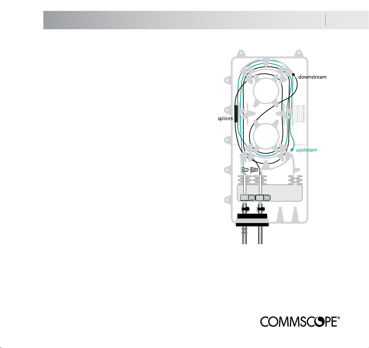
Tap enclosure and optical tap module
The tap enclosure consists of three main sections; a distribution side for connection to the network, a drop side for connection to the residence and, sandwiched between them, the optical tap module. The tap is a passive (non-powered) device that can be ordered with anywhere from two to eight connectorized
outputs and non-connectorized fibers that permit the signal to continue along
the distribution cable. The distribution cable fibers are fusion-spliced to the tap.
Drop cables are connectorized and plugged into adapters in the drop side.
Network Interface Device/Network Interface Unit
The NID attaches to the side of the residence and houses the NIU, a powered optical
converter/amplifier that converts the downstream 1550 nm signal into RF for distribution in the home. It also converts RF into a 1310 nm optical signal for transmission
back up the same fiber toward the headend. The NIU draws low-voltage power at the
residence. The NIU is secured in the NID after the NID is attached to the residence.
Optical node (for node-based systems)
The optical node amplifies and splits headend signals for downstream distribution at the 1550 nm wavelength and upstream at the 1310 nm wavelength. A
diplexer separates the signals. The node significantly increases the 1550 nm signal using an EDFA amplifier and divides it into eight fiber outputs. Typically, two
four-fiber distribution cables will leave the node.
Upstream 1310 nm signals return on the same fiber. The node conditions and
multiplexes them for transmission back to the headend over the same feeder
fiber as the 1550 nm signal. The node is powered like a coaxial amplifier.
distribution
side
drop
side
Page 13

Cable and components storage and handling
Cable storage
While both the cable and fiber optic cable in conduit (FOCIC) are built to work in buried environments, they should be
stored in a covered location where the temperature range is no greater than -40° F to +158° F (-40° C to +70° C).
Reels are shipped on pallets and should remain on them until ready to install.
Moving reels
Unpalleted reels can be moved by rolling on their flanges or with a forklift. An arrow on
the reel shows roll direction.
Use the forklift to pick up the reel so that the side of the reel faces the driver. DO NOT lift
the reel by placing the tines between the flanges.
DO NOT let the tines touch the cable.
Components
The optical node, taps, NIDs and NIUs should be stored indoors until the day of installation. Nodes should be
tested at the shop prior to field installation.
Because the optical tap modules vary with the number of drops they serve, they should be ordered after the installation planning is complete. The tap housings also require grommets to match the type of distribution cable being
used (see page 3.5).
Page 14

4.2 Before Installation
Route survey
Route survey
Prior to installation, a careful route survey should be done to determine the best path for the distribution cable and
the location for the optical taps.
BrightPath® permits a great deal of flexibility in installation. The singlemode fiber architecture permits runs of miles
without the need for amplification. The taps are passive devices, so power is only needed at the optional node and
at the residence. Recall that a direct feed installation can serve up to 32 subscribers per fiber, while a node-based
system can serve up to 256 subscribers.
With this said, the locations of the taps must be carefully planned, especially for buried installations.
Page 15

Underground Distribution Cable Installation 5.1
Overview
Buried installation of BrightPath® distribution cable
BrightPath cable can be either directly buried or buried as fiber optic cable in conduit (FOCIC). It can be plowed
into position using a vibratory plow or buried in a trench. Buried BrightPath cable should be installed at least 18 in.
(45 cm) deep, and deeper if the frost line is farther down.
For vibratory plowing instructions, see pages 5.2 to 5.3.
For trenching instructions, see pages 5.4 to 5.8.
Upstream/headend orientation
Whatever method you choose, keep in mind which end of the cable/FOCIC is the
upstream end. The BrightPath taps will not work properly if they are installed backward. Always know which end is upstream (the side pointed toward the headend)
and mark it per instructions.
Handling FOCIC
FOCIC reels are substantially larger than traditional cable reels. Work with your CommScope customer representative to make sure your carrier can accommodate FOCIC reels.
Cut the cable restraint before installation
Prior to installation, remove the FOCIC end cap and cut the cable restraint. This relaxes the cable and transfers all
of the pulling tension to the conduit. Replace the cap immediately.
Keep the FOCIC capped
Make sure both ends are capped during installation to maintain conduit integrity.
Leave more than enough cable for splicing to the headend cable or node
IN ALL CABLE INSTALLATION SCENARIOS, MAKE SURE THAT YOU LEAVE SUFFICIENT CABLE FOR ATTACHMENT TO THE HEADEND CABLE OR THE NODE. The node may not yet be in place when the cable is being
installed. Confirm the planned location of the node before installation.
For BrightPath
taps to operate,
they must have
a correct
upstream/
downstream
orientation
Page 16

5.2 Underground Distribution Cable Installation
Vibratory plowing
Vibratory plowing cable/FOCIC
CommScope strongly recommends a professionally-engineered single or double feed tube plow blade with a tube
at least 1/2 in. (13 mm) larger than the largest cable size and a radius of 12 in. (30 cm) or larger. At minimum, an
operator and a helper/feeder are needed for a plowing installation. Because terrain and soil types vary, contact your
plow manufacturer for their equipment recommendation.
Dig a trench deep enough and at least twice the length of the plow blade/chute for the plow blade to enter it
comfortably. A similar trench should be dug at the other end of the installation and at every pedestal location. The
cable/FOCIC may pay-off from the front of the tractor or from a stationary cable reel.
In the tractor method, make sure the reel is not run into objects that may damage the cable. Pay the cable over the
top of the reel. Do not use reel brakes.
In the stationary reel method, pull the cable end from the reel to the starting trench. Use cones to mark and protect
the cable/FOCIC from pedestrian and vehicle traffic.
Cap the FOCIC or tape the cable end to protect it. Remove the back plate from the blade and inspect the feed tube
for burrs, rough surfaces and sharp edges. Clean out any dirt or rocks. Carefully place the cable in the feeder tube.
Reattach the back plate. Pull enough FOCIC to connect to the splice point.
Page 17

Underground Distribution Cable Installation 5.3
Vibratory plowing
Vibratory plowing cable/FOCIC - preparing pedestal locations
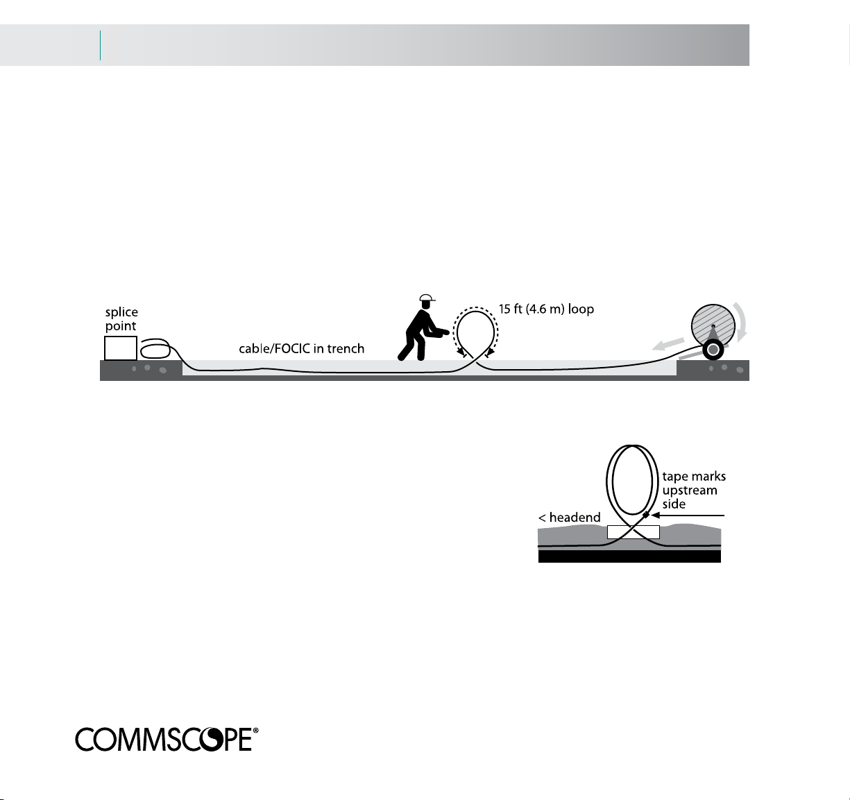
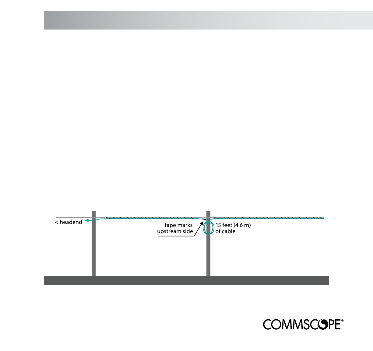
Stop the plow at each pedestal location. Draw at least 15 feet (4.6 m) of cable/FOCIC through the plow blade.
Twist the loop so that the cable/FOCIC crosses itself at ground level. The top of the loop will be head-high on an
average-sized person. Plowing may now continue to the next pedestal location.
If your run exceeds the length of a reel of FOCIC, start the next reel at the pedestal location. Leave at least 7.5 feet
(2.3 m) of FOCIC above ground. Cap each open end.
Page 18

5.4 Underground Distribution Cable Installation
Trenching for 1000 feet or longer
Trenching cable/FOCIC - runs of 1000 feet (304 m) or longer
This technique is recommended for runs of 1000 feet (304 m) and longer, but can be used for shorter runs as well.
The length of the cable/FOCIC should be the length of the trench PLUS 15 feet (4.6 m) for every pedestal. Leave
sufficient cable/FOCIC at the upstream end to permit connection to the splice point. Keep track of the upstream end
– the tap must be correctly oriented with the headend for the system to operate.
Use a tractor to make a trench 18 in. (45 cm) deep along the route. Make sure the trench bends are not tighter
than the cable/FOCIC bend radius. Back-pull the cable/FOCIC into the trench.
Set the cable/FOCIC at the pedestal locations
Starting at the far end, back-pull enough cable/FOCIC at each pedestal location to create a loop of at least 15 feet
(4.6 m) in circumference. The top of the loop will be head-high on an average-sized person. Twist the loop so that
the cable/FOCIC crosses itself at ground level.
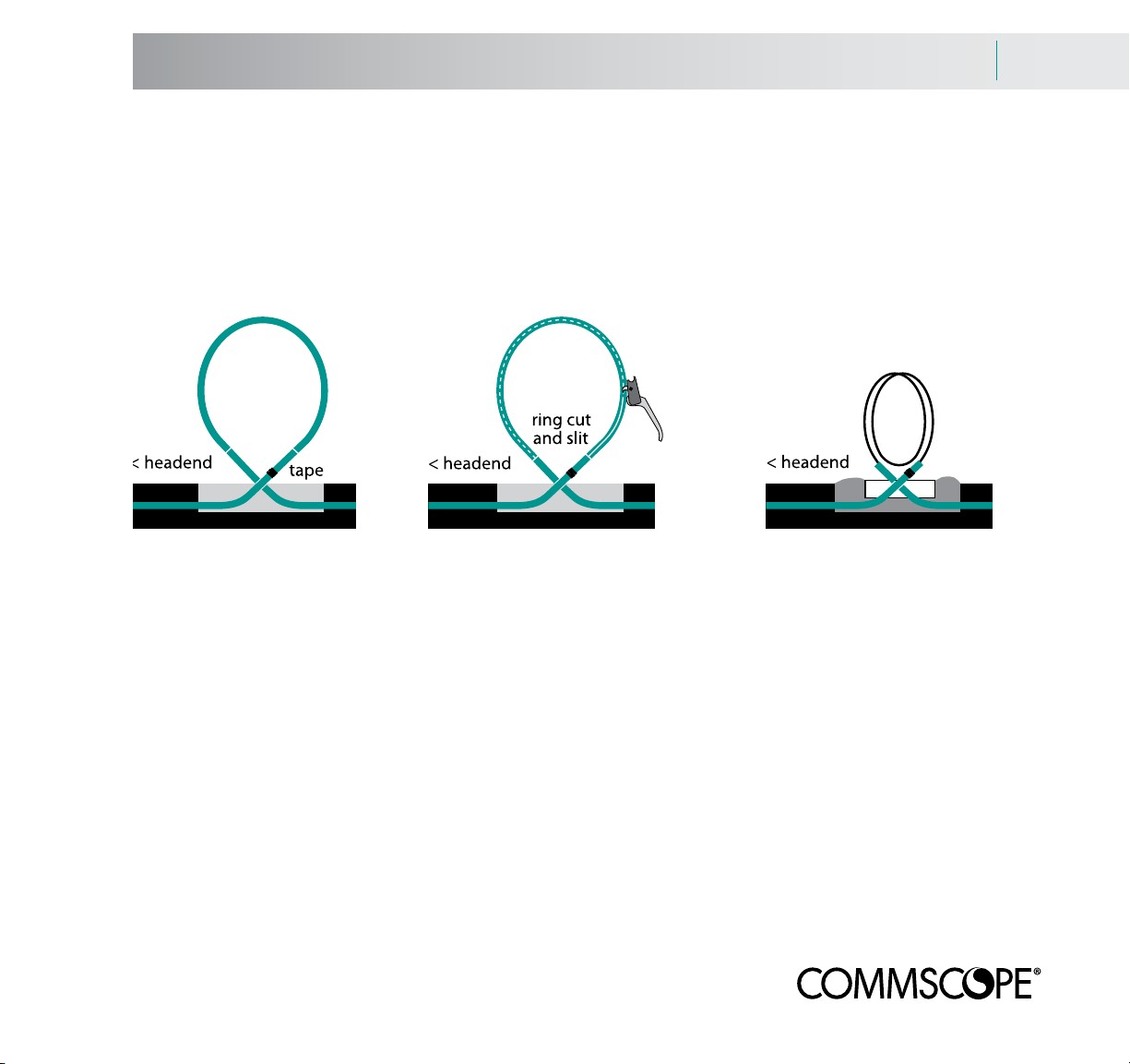
Mark the upstream/headend end of the cable/FOCIC with several wraps of tape.
Page 19
Underground Distribution Cable Installation 5.5
Trenching for 1000 feet or longer
Conduit removal and placing the pedestal
Cut and remove the conduit
If placing FOCIC, mark two ring cut locations on the conduit 14 feet (4.3 m) apart or 7 feet (2.1 m) from the center
of the loop. Use a ring cutter to cut the conduit. Slit the conduit between the ring cuts with a mechanical conduit slitter. Remove the cut conduit.
Place the pedestal
If placing FOCIC, leave about 6 in. (15 cm) of each end of conduit above ground level. Fill the trench and tamp
down the dirt. Place the pedestal base over the conduit ends and bury it the recommended depth in the dirt. Backfill
the trench.
Loop the cable so that the pedestal cover will fit properly. Place the pedestal cap in position.
Page 20
5.6 Underground Distribution Cable Installation
Trenching for 1000 feet or less
Trenching FOCIC - runs of less than 1000 feet (304 m)
This technique is used for runs of less than 1000 feet. The length of the cable/FOCIC should be the length of the
trench PLUS 15 feet (4.6 m) for every pedestal. Leave sufficient cable/FOCIC at the upstream end to accommodate
termination to the splice point. When placing and cutting the cable/FOCIC, keep track of the upstream end – the
tap must have a correct upstream orientation for the system to operate.
Use a tractor to make a trench 18 in. (45 cm) deep along the route. Make sure the trench bends are not tighter
than the FOCIC bend radius. Back-pull the cable/FOCIC into the trench.
Set the pedestal locations
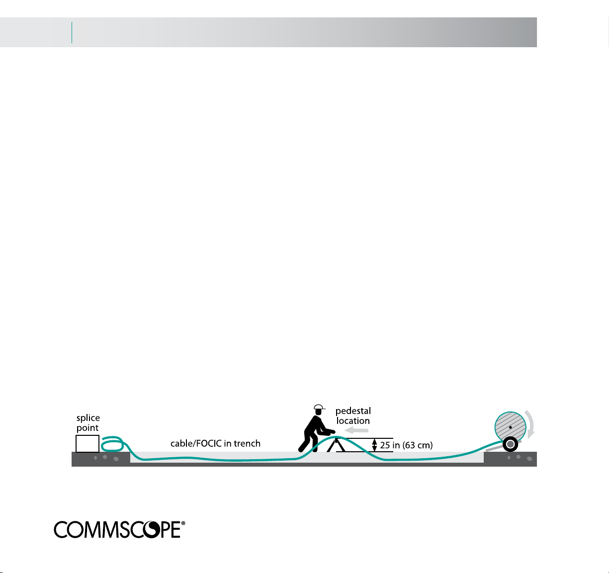
Place the cable/FOCIC in the trench. Starting at the end away from the reel, raise a half loop of FOCIC with its
crest two feet above the ground at every pedestal location. Use a sawhorse with its legs cut to a height of 25 in. (63
cm) to support the cable at that height.
Page 21

Underground Distribution Cable Installation 5.7
Trenching for 1000 feet or less
Trenching FOCIC - runs of less than 1000 ft (304 m)
Cut and remove the conduit
If placing FOCIC, ring cut the conduit at the midpoint of the half loop. Mark the upstream/headend end of the conduit with several wraps of tape.
Back-pull at least 15 feet (4.6 m) of cable out of the conduit or the same amount of cable. Twist the cable loop so
that the cable crosses itself at ground level. NOTE: back-pulling the cable will create empty conduit at the far end of
the pull that will be cut off after installation. This conduit may be saved and used where the buried drop emerges at
the residence (see pages 9.5 and 9.6).
Push the conduit back into the trench leaving 6 in. (15 cm) of each end exposed above ground level. Fill the trench
and tamp down the dirt. Place the pedestal base over the conduit ends and bury it the recommended depth in the
dirt. Backfill the trench.
Loop the cable so that the pedestal cover will fit properly. Place the pedestal cap in position.
Page 22
5.8 Underground Distribution Cable Installation
Trenching for any distance
Trenching cable - runs of any distance
This technique may used for cable runs of any distance. The length of the cable should be the length of the trench
PLUS 15 feet (4.6 m) for every pedestal. Leave sufficient cable at the upstream end to accommodate termination to
the splice point. When placing and cutting the cable, keep track of the upstream end – the tap must have a correct
upstream/headend orientation for the system to operate.
Use a tractor to make a trench 18 in. (45 cm) deep along the route. Make sure the trench bends are not tighter
than the cable bend radius. Back-pull the cable into the trench.
Set the pedestal locations
Place the cable in the trench. Starting at the end away from the reel, pull and
loop at least 15 feet (4.6 m) of cable. Mark the upstream/headend end of
the cable with tape.
Fill the trench and tamp down the dirt. Place the pedestal base over the conduit ends and bury it the recommended depth in the dirt. Backfill the trench.
Loop the cable so that the pedestal cover will fit properly. Place the pedestal
cap in position.
Page 23

Aerial Distribution Cable Installation 6.1
Overview
Aerial installation of BrightPath® distribution cable
While buried installation is the preferred method for placing BrightPath distribution cable, aerial installation is
possible.
INSULATED GLOVES SHOULD BE WORN BY ALL PERSONNEL THAT ARE IN CONTACT WITH
BRIGHTPATH CABLES UNTIL THE CONDUCTIVE COMPONENT OF THE CABLE IS BONDED TO THE
GROUNDING NETWORK.
Take care to ensure that construction personnel do not use bare hands to touch the messenger or cable. Constant
inspection and certification of insulated gloves is recommended.
NOTICE – SELF SUPPORTING FIBER CABLES SUCH AS FD (FLAT DROP) WITH SPAN LENGTHS
OVER 125 FEET IN HEAVY LOADING CONDITIONS WILL REQUIRE ADDITIONAL ENGINEERING
SUPPORT.
PLEASE CALL BROADBAND TECHNICAL SUPPORT @ 866-333-3272
Page 24
6.2 Aerial Distribution Cable Installation
Drive-off/moving reel set-up
Aerial installation - drive-off / moving reel set-up and lashing
Trailer set-up
Pay the cable off the top of the reel rotating toward the rear of the cable trailer. Use minimal reel braking.
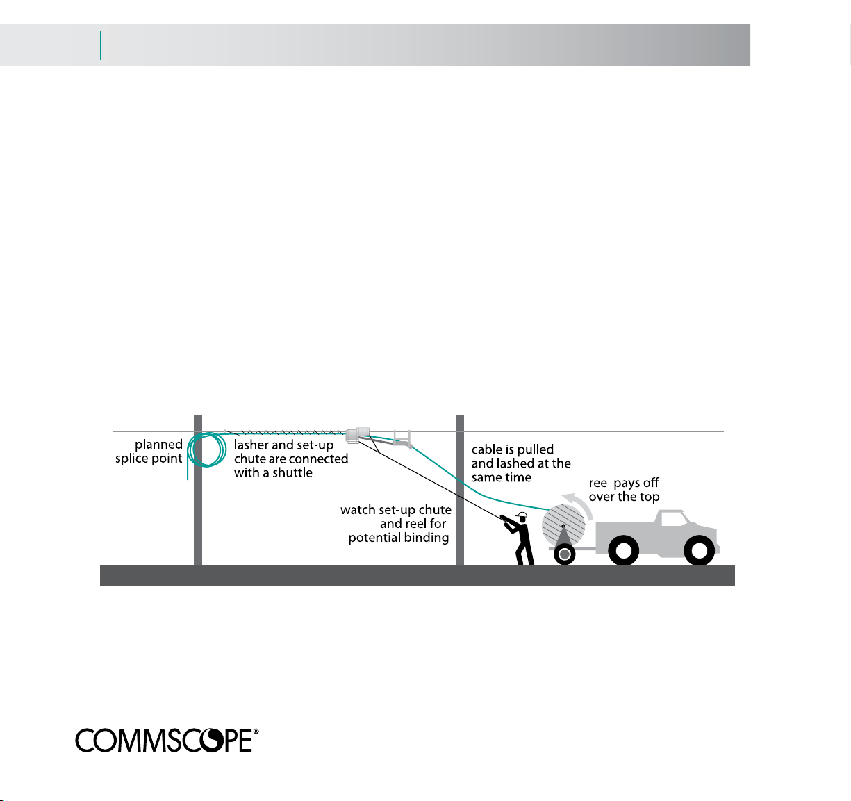
Attaching the lasher, set-up chute and cable
Attach a lashing wire clamp to the strand far enough from the initial pole to accommodate the splice closure or the
node. Place the lasher on the strand and attach the lashing wire to the lashing wire clamp.
Position the set-up chute in front of the lasher and attach it to the lasher with a block pusher (or shotgun). Attach the
pull line to the set-up chute or lasher.
Thread the cable through the set-up chute and place the cable in the lasher. Leave sufficient cable tail to accommodate a loop, splice or equipment. Close the lasher gates.
The cable should move only through the chute. If the pole-line is offset from the reel, observe the cable closely as
it moves through the chute. Cable reel offset may cause the cable to drag on the reel flange and the cable in the
chute to bind.
Page 25
Aerial Distribution Cable Installation 6.3
Drive-off/moving reel and leaving cable at the pole
Aerial installation - drive-off / moving reel - passing the pole
Passing the pole
Attach a lashing wire clamp far enough from the pole to accommodate the tap. Open the lasher gates. Disconnect
the set-up chute, pusher and lasher and pass them across the pole-face. Place them on the unlashed strand and
reassemble them.
Close the lasher gates. The lasher cannot be pulled backward along the strand while the gates to the lasher are
closed. Cut the lashing wire and secure it to the lashing wire clamp. Make sure that the lashing wire does not loosen
from around the cable.
Attach another lashing wire clamp to the strand on the unlashed side of the pole allowing enough room for a tap.
Connect the wire from the lasher to the new clamp.
Place the cable in the set-up chute and the lasher.
Rotate the cable reel to take up any excess slack. Continue until the installation is complete.
Leave cable at planned tap locations
When passing the pole at planned tap location, coil 15 ft (4.6 m) of cable and store it on the pole. Mark the
upstream side of the loop with tape (like on page 5.8).
Page 26

6.4 Aerial Distribution Cable Installation
Overlashing
Installation - overlashing existing cable
Overlash cable placement
Overlashing cables onto existing cable plant is similar to installing cable onto new strand. However, there are some
unique aspects:
A sag and tension analysis should be performed to see if the new cable load will overwhelm the strand.
Use special overlash cable puller blocks and continuously maintain and monitor the pulling line tension. Overlash
cable pullers do not have a strand brake and will be pulled backward on the span by the tension in the cables being
pulled.
Use cable blocks designed specifically for overlash applications. Place them onto the cable bundle with a cable
block lifter and lift the cable with a cable lifter. During lashing, remove the cable blocks from the cable bundle with
a cable block lifter. DO NOT PUSH THE CABLE BLOCKS IN FRONT OF THE LASHER AS THAT MAY DAMAGE
EXISTING CABLES.
Remove all straps and spacers from the existing cable bundle during lash-up. New straps and spacers may be
required - check the old ones carefully to see if they need replacing.
Page 27

Optical Node Installation 7.1
Node description
Optical node attachment for node-based systems
NOTE: Proceed to Section 8 if installing a direct system.
The optical node splits optical signal from the headend into eight ports and amplifies it for transmission along the
BrightPath® cable. The node is connected to fiber input and output by a service cable. The service cable is connectorized at one end for attachment inside the node case. The other end of the service cable is spliced to the ends of
the input (headend) and output (distribution cable) fibers.
Prior to mounting, test the node at the shop.
The optical node is powered by a connection through either a coaxial cable or a power source at the node. The
node can be suspended from a horizontal cable (strand mount) or mounted in an enclosure or equipment room
(pedestal or surface mount).
Strand mounting
Two strand clamps are attached to the top of the node enclosure to mount the node horizontally below the suspension strand.
Use a 1/2 in. wrench to loosen the clamps enough to allow the clamps to fit over the suspension strand.
Hang the optical node from the strand by the clamps. Tighten the two bolts enough to hold the enclosure on the
strand BUT DO NOT tighten the bolts all the way yet, as you may need to move the node on the strand to accommodate power cables and fiber optic service cables.
Only when all power cables and fiber optic service cables are connected to the node should the clamp bolts be fully
tightened. Ground the enclosure, using a split-bolt grounding stud.
Pedestal or surface mounting
Two threaded holes are located on the horizontal centerline of the base housing.
Remove the pedestal mounting plate. Remove both strand clamp bolts - they will be used to fasten the base to the
pedestal/surface mount.
Lay the node housing with the lid side facing down. Place the mounting plate on top of the base housing and align
the mounting plate holes with the two holes on the base housing.
Secure the mounting plate to the node housing with bolts removed from the strand clamps.
Page 28

7.2 Optical Node Installation
Node installation
Optical node installation outline
Ground the node prior to opening it. A split-bolt grounding nut is provided. For pedestal mounting, the grounding
nut is attached to either of the strand clamp mounting holes. For strand mounting, the grounding nut is attached to
the base.
General instructions
The following is an outline for installing and powering the node. The diagram has been simplified for clarity.
Consult the installation instructions that came with the node for detailed information.
Once the node is attached
and grounded, the case may
be opened. The power chassis
needs to be removed prior to
attaching the powering cables
which enter through the unit’s
sides.
The node is connected to the
head end and distribution cable
fibers by means of a service
cable. The service cable is terminated with an eight-fiber low loss
MPO connector that plugs into
the node. The other end of the
service cable has bare fibers that
are spliced to the head end and
distribution fibers.
Spliced fibers need to be protected inside a weatherproof splice
closure. Refer to instructions that come with the splice closure for specific installation practices.
Page 29

Optical Tap Installation 8.1
Introduction
Optical tap installation - introduction
Once the distribution cable is placed, it can be entered and attached inside the
optical tap enclosure. The enclosure can be placed either in a pedestal or on the
aerial span.
The BrightPath® tap enclosure is a weather-hardened unit where the distribution
cable’s ends are secured and one fiber is attached to an optical tap module that
splits the optical signal into as many as eight drops. The enclosure consists of three
sections:
The distribution side, where both the upstream and downstream ends of the
distribution cables are secured and one selected fiber is spliced to the tap,
The drop side (shown in the illustration), where up to eight drop cables are
spliced to the tap outputs and secured, and
The optical tap module, which is sandwiched between the distribution and
drop sides. The tap module is already connectorized with both spliceable fibers
exposed; there is no need to access the tap module during normal installation.
The upstream/input fiber is tagged with an “I” and the downstream/output fiber is
tagged with an “O.”
Upstream/headend orientation
This diagram shows the distribution side of the tap enclosure. Note that the cable
entry area is marked “IN” for the upstream/headend side of the cable and “OUT”
for the downstream side.
Remember, the cables must be oriented correctly for the system to operate.
Cable entry grommets
Distribution cables come in different size/constructions for the different cable. Make
sure that you order the correct size grommet for your cable.
Page 30

8.2 Optical Tap Installation
Midspan entry
Midspan entry of BrightPath® distribution cable
Details for midspan entry for the suggested BrightPath distribution cables are contained in CommScope’s
BrightPath Tap Installation document. Prior to beginning mid-span entry, make sure these tools and materials
are handy:
Fiber optic strippers (e.g. Ripley FO 103-S)
Round cable stripper (e.g. Ripley RCS-114)
Armored cable stripper (e.g. Ripley ACS-100)
Buffer tube cutter (e.g. Ideal 45-162)
Phillips head screwdriver
5/16” nut driver
Scissors or snips
Utility knife
Needle nose pliers
Tape measure
7/16” wrench
Cable ties
Optical power meter
Water-based lubricant
40 feet of #6 AWG solid copper wire
Page 31

Optical Tap Installation 8.3
Splicing equipment
Splicing
Fiber splicing – overview
Once the fiber has been exposed and the cable secured in the housing, the fiber can be spliced. Fiber splicing
requires specialized tools and supplies:
Fiber splicer with a fiber positioning system and test function
Fiber stripper
Fiber cleaver
FIS splice protection sleeves (F1100240) [drop/branch splicing]
Small lint-free tissues (Kimwipes™ or similar brand).
Optical fiber cleaning kit (95 - 97% isopropyl alcohol packs, cleaning tape)
Optical power meter
Fusion splicers integrate a heat source (usually an electric arc), clamps for holding the fibers, a fiber positioning
system and a splice viewing/loss measurement system. The simplest units use a ‘V’ groove to mechanically match
the fiber’s outer diameters. More sophisticated splicers feature automatic alignment of the fiber cores.
Fiber alignment is tested for the lowest-loss splices using one of these two methods:
LID (Light Injection and Detection) systems ‘inject’ light into the fiber and measure its power on the output
side, manually/automatically aligning them for the lowest loss. LID systems monitor the fibers as they are being fused
and shut off the arc when the lowest splice loss is detected.
PAS (Profile Alignment System) systems display an image that shows the fiber cores, manually/automatically
brings them into alignment and fuses them.
Page 32

8.4 Optical Tap Installation
Splicing
Splicing
The following instructions are general practice for fusion splicing. Refer to the instructions that came with the splicer
on how much buffer to strip, recommended cleavers and other specifics.
Prepare the distribution upstream fiber
Find the midpoint of the fiber to be spliced into the tap module.
Use the fiber cleaver to cut the selected fiber at the midpoint. Place the
splice protection sleeve over the upstream end of the fiber and let it
slide toward the buffer tube.
Use the fiber stripper to remove the fiber buffer. Clean the fiber with a
lint-free cloth soaked in 95 - 97% isopropyl alcohol to remove the buffer residue. Avoid touching the bare fiber.
Use the fiber cleaver again to achieve a perpendicular face for the
fiber.
Prepare the tap upstream fiber
Strip, clean and cleave the optical tap’s upstream/input fiber (with the “I” tag) using the method above. Place both
fiber ends into the splicer and initiate the splice sequence.
Splice the fibers together
The splice should have a loss of no more than 0.04 dB. If the loss is
higher, cut the fiber and repeat the splicing process.
Position the sleeve
Once the fiber is successfully spliced, place the splice protection sleeve
over the splice and activate it. Most sleeves use a heat-shrink plastic
reinforced with a metal rod. (The unit shown has an integrated sleeve
heater shown at the bottom of the photo).
Repeat the process with the downstream fiber
Splice the tap module’s downstream/output fiber (with the “O” tag) to
the remaining fiber segment using this same technique.
Page 33
Optical Tap Installation 8.5
Fiber arrangement and testing
Arranging and testing the fiber
Once the mechanical sleeves have been heat-shrunk, snap them into
the slots to the left of the fiber management tracks. Then, arrange the
fibers in the management tabs, being careful to avoid tight bends.
The diagram at right shows a possible arrangement within the tabs.
An exact routing is difficult to recommend because of variances in
installation practice. However, the inner and outer tracks provide
any number of possible routes. The only essentials are to avoid tight
bends and keep the fiber under the tabs.
Testing the splice
Fiber optic splices should be tested for continuity and attenuation. A
hand-held power meter works well.
To test the splices, a 1550 nm signal is sent from the headend, the
node or a light source at the upstream end of the distribution cable.
Remove the dust cover from the tap connector and clean the surface
with the isopropyl alcohol solution and a lint-free wipe. Connect it to
the power meter and activate it. The meter should read between
-5 dBm and 0 dBm.
LA and LN cables have additional buffer tubes. They can be
coiled until they fit inside the casing. Tie the loops together with cable
ties and lay them loose on top of the management tabs.
Seal the enclosure and attach it
The distribution side of the enclosure can now be closed and sealed. The enclosure can now be attached to the
frame of the pedestal or the pole hardware at the holes in the tabs at either the top or side of the enclosure. The
CommScope universal mounting bracket that came with the tap is recommended.
Page 34

9.1 Drop and NID/NIU installation
Introduction
Introduction
The drop cable connects the tap to the NID/NIU located on the structure. As outlined on
page 3.5, the drop cable is either the DF/BP flat cable or the DA/BP armored central tube
cable. Both cables can be buried; the DF flat cable is self-supporting for aerial installations.
Please consult the DF cable spec sheet for span distances.
Tap enclosure and optical tap module
The drop side of the tap enclosure has up to eight connectorized bulkhead adapters. Drop
cables are threaded through the grommets shown at the bottom of the diagram; they are
attached to the enclosure by cable ties and by securing their strength members with retaining
screws.
With adjustment, the grommets fit either DF/BP or DA/BP cables.
Fibers are spliced to SC/APC pigtails (connectors with fibers attached), placed in the fiber
raceways and plugged into the appropriate bulkhead adapter.
Network Interface Device (NID) and Network Interface Unit (NIU)
The NID consists of a weather-hardened enclosure that contains the NIU, an electro-optical converter/transmitter
and fiber connection, behind a craft-accessible door.
Power for the NIU is provided from the residence, either inserted
over the RF coax or though an independent connection. Drop
cable is terminated at the enclosure and the prepared fiber is
spliced to a pigtail. Grounding is required.
Page 35

Drop and NID/NIU installation 9.2
Planning the drop
Planning the drop
The time taken in examining the route prior to installation is well spent and can help you avoid problems later on.
You need to be aware of issues such as right-of-way (ROW), pedestal/tap location and the distance covered by the
drop. If using the DA armored cable, you will need to attach and ground the cable’s armor at the NID.
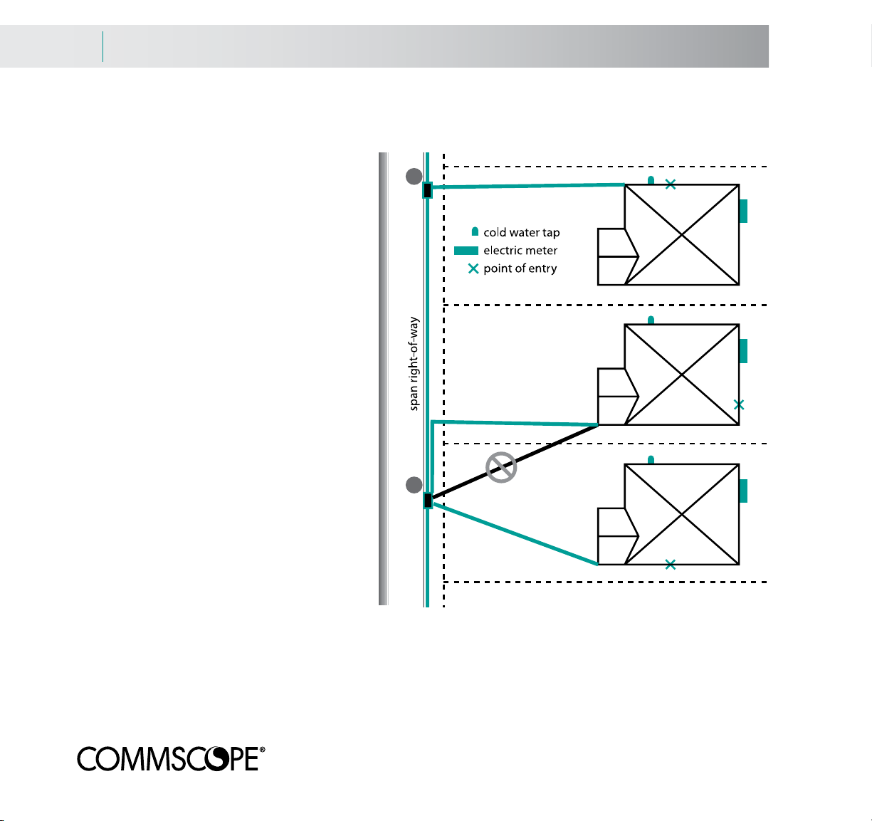
Know your ROW (Right-Of-Way)
The most direct route may not be the legal route. Make sure the route you’re planning runs ONLY over/under the
customer’s property. Generally, you can follow a parallel path to power or phone lines. NOTE: under no circumstances lash the drop to any other cable.
Locate the tap
The BrightPath® tap can accommodate as many as eight drops. The length of the drop is rarely an issue. The
BrightPath singlemode signal can travel a half a mile or more, so long paths that avoid architectural details or landscaping are easily handled.
Select your attachment point for ease of grounding and access
If replacing an older coaxial installation, the existing entry point should already be grounded. In a new installation,
the home may already have an access point chosen.
If you are selecting the access point, try to attach the cable to the wall or corner nearest the meter. If that can’t be
reached, an exterior cold water pipe (if the plumbing throughout the building and back to the main is entirely metal)
or an existing ground rod will do. If these are impractical, you will have to hammer in a ground rod.
In short, keep grounding issues in mind when placing the NID.
Page 36
9.3 Drop and NID/NIU installation
Attachment examples
Attachment examples for running the drop
Pedestal and NID/NIU locations should be
considered with both ROW and grounding
issues. The top example shows a straightforward installation. The electric meter is on the
opposite side of the building from the span,
so attachment near the cold water tap is
acceptable.
The middle example shows that the most
direct route would trespass on neighboring
property. Therefore, the drop should be buried (or run along the span) and then angled
to the building, eventually running toward the
meter and then back to the point of entry.
The bottom example is a tough call. It’s
marginally shorter to attach near the point
of entry, run to the meter for grounding purposes and double back to the point of entry.
In all cases, check your local code requirements and system design specifications for
your prescribed grounding requirements.
Tips for grounding the NIU
Attach the NID/NIU as close as possible to
the electrical meter. The ground wire should
run horizontally. The grounding wire (14 - 6
AWG in most cases) should be as straight as possible.
If grounding to the meter is not possible, you may ground to an exterior metal cold water pipe running into the
earth. As a last resort, you may drive an 8’ ground rod into the earth and attach the bonding wire to that, but you
will need to ground ALL of the grounds of the residence to that rod.
Page 37
Drop and NID/NIU installation 9.4
Attaching and grounding the NID
Attaching and grounding the NID
Specific instructions for attaching and installing the NID/NIU are contained in the BrightPath® NIU Installation
document. Prior to installation, make sure these tools and materials are handy:
Fiber optic strippers (e.g. Ripley FO 103-S)
Round cable stripper (e.g. Ripley RCS-114, Ripley ACS)
Buffer tube cutter (e.g. Ideal 45-162)
Pigtail (e.g. CommScope ZFT-01BF09-8WSCA-01-BK)
Phillips head screwdriver
5/16 in. nut driver
Scissors or snips
Utility knife
Needle nose pliers
Tape measure
Coaxial cable (e.g. CommScope F677TSVV)
Coax stripper
Coax crimp tool
7/16 in. wrench
Cable ties
RF power meter
Water-based lubricant
Materials to connect the NIU to the main grounding system per NEC 820
Misc. tools needed to attach the NID to the customer premise dependent on the type
of material (i.e. wood, brick, stucco, etc.)
NOTE: The NID can be attached to the residence prior to placing the drop cable. As mentioned in the installation
document, do not attach the drop cable until the NIU has been grounded.
Page 38
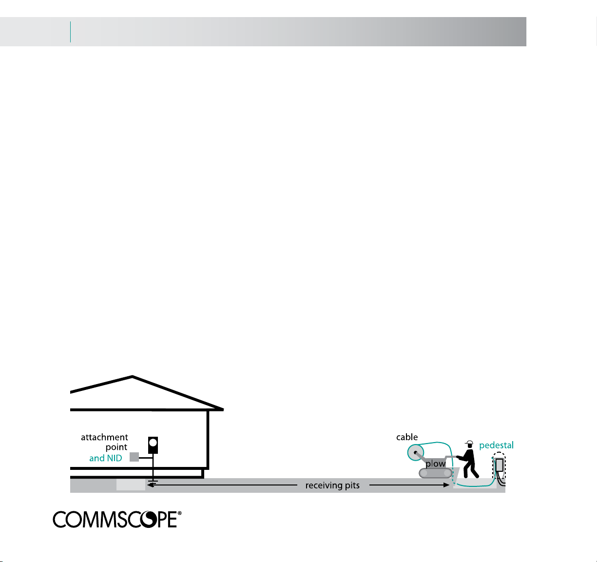
9.5 Drop and NID/NIU installation
Plowing overview
Buried installation - plow from the pedestal
BrightPath® drop cable may be installed by trenching or plowing. BrightPath drop cables should be buried to a
minimum depth of 12 in. (30 cm) or 18 in. (45 cm) in colder climates. START PLOWED INSTALLATIONS AT THE
PEDESTAL.
Use a plow chute with a radius equal to (and preferably larger) than the minimum bend radius of the drop cable.
The chute width should be at least 1/2 in. (13 mm) larger in diameter than the cable.
At the pedestal and residence, dig receiving pits between 12 and 18 in. (30 and 45 cm) in depth, 6 in. (15 cm) wide,
18 in. (45 cm) long and in the direction of planned line of the installation. The plow blade should be able to fit easily
in these pits. (The residence pit may need to be longer as the plow may not be able to get close to the NID).
Remove the pedestal cap and dig a hole to meet the receiving pit. Place the plow blade completely in the ground.
CAREFULLY feed the drop cable through the plow blade and run it to the bottom of the pit and up through the pedestal base. Store at least 7.5 feet (2.3 m) of cable in the pedestal.
The cable may pay-off from the front of the walk-behind plow or from a stationary reel along the route. In the walkbehind plow method, pay the cable over the top of the reel. Do not use reel brakes. In the stationary reel method,
pull the cable end from the reel to the starting trench.
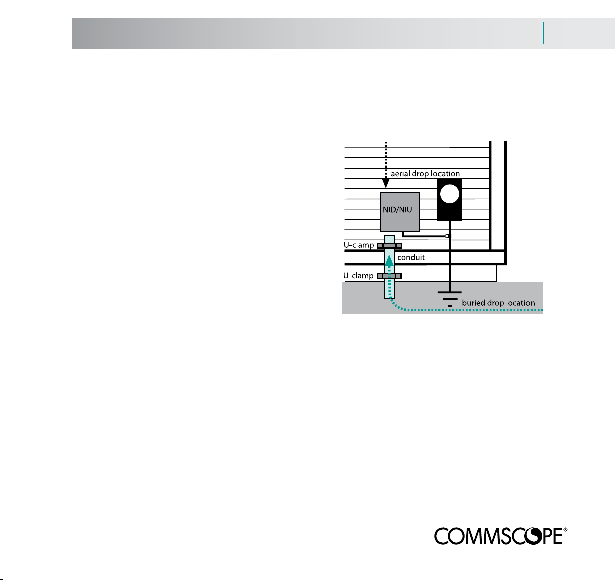
At the residence, CAREFULLY feed the drop cable through a piece of conduit 18 in. (45 cm) long. This will be used
to protect the cable when it is attached to the NID.
The drop cable can now be attached and spliced per
CommScope’s BrightPath tap and NIU installation documents.
Page 39

Drop and NID/NIU installation 9.6
Trenching overview
Buried installation - trench from the residence
BrightPath® drop cables should be buried to a minimum depth of 12 in. (30 cm) or 18 in. (45 cm) in colder climates. START TRENCHED INSTALLATIONS AT THE RESIDENCE.
Dig the trench as straight, level and rock-free as possible.
Drop cables can be placed in the trench. If the cable is on a reel, mount the reel so that pay-off is underneath
toward the direction of the pull.
Pull and place the cable in the trench while walking toward the pedestal. Remove the pedestal cap and dig a hole to
meet the trench.
CAREFULLY feed the drop cable from the trench and up through the pedestal base. Store at least 7.5 feet (2.3 m) of
cable in the pedestal. Fill a few feet of the trench to hold the cable in position.
Go back to the residence and CAREFULLY feed the drop cable through a piece of conduit 18 in. (45 cm) long. This
will be used to protect the cable when it is attached to the NID.
The drop cable can now be attached and spliced per CommScope’s BrightPath tap and NIU installation documents.
Page 40

9.7 Drop and NID/NIU installation
Aerial installation
Aerial installation
Aerial installation is an alternate method to run the BrightPath® drop. If considering this method, make sure that
there are no local covenants against aerial installations of cable.
CommScope DF/BP flat drop cable works well for aerial installations.
A typical installation is shown below. Drop cable runs from the tap to the attachment point on the residence and
continues to the NID and the ground block. Drop wire clamps attach to hooks at the pole and the residence. If you
are using DA armored cable, it will require grounding at the NID/NIU.
Be careful to observe minimum distances above the ground or objects.
Page 41

Drop and NID/NIU installation 9.8
Pulling cable and pole attachment
Aerial installation - pull the cable and attach the cable
Starting from the residence, walk the cable end to where the tap will be located. Don’t let the cable kink, scrape,
tangle or get hung up as you walk. Pull enough cable to allow easy access to the tap. With the correctly-sized drop,
there should be enough cable at the residence to permit connection to the NID. Repeat this for every drop running
to this tap.
Attach the drop wire clamp
Attach a Q-hook to the pole or span. DF/BP flat cable can be attached to the hook using a drop wire clamp
normally specified for 1-2 pair telephone wire or fiber cable. We suggest a stainless steel three (3) piece clamp with
a serrated shim. Senior Industries #SI-0972 (Or Equivalent)
These designs use a shim to trap the cable in the clamp’s shell, and then use a wedge to tighten the shim. The
weight of the cable produces tension that tightens the wedge in the shell to secure the cable.
cable Place shim on top of cable. Slide wedge in through the
shim
wedge
Fig. 1 Fig. 2 Fig. 3 Fig. 4
shell
bottom end of the shell
assembly.
While holding shell pull wedge
forward to set cable in place.
Drop wire clamp can
now be attached to
the Q-hook
mounted to
pole.
Page 42

9.9 Drop and NID/NIU installation
Attaching the cable to the residence
Attach the cable to the residence
Using a ladder or a lift truck, climb up to the attachment point and screw or drive a P-hook or Q-hook into the residence. A good attachment point is the corner of the house under the soffit. NEVER attach to an antenna, rain gutter,
chimney, power mast or lightning rod. The hook should be parallel to the ground.
The attachment point should not be any closer than 4 in. (10 cm) from a telephone cable or 1 foot (30 cm) from a
power line. Make certain you meet all clearance requirements.
Taking the cable in hand, climb up to the attachment point. Pull the cable
taut until the sag is 1% of the overall length of the drop (examples: for a
100’ run, the sag should be 1 foot; for a 50 foot run, the sag should be
1/2 foot). Use your hand to mark the place on the cable where the cable
and the hook meet while maintaining proper sag. DO NOT pull the cable
through the hook or attach it to the hook.
Attach the drop wire clamp
Select a point on the cable where the drop wire clamp’s wedge would meet the cable if the clamp were attached
to the hook. Use the technique described on page 9.8 to trap the cable in the clamp’s shell with the shim. Slide the
wedge into the clamp. The cable sag can be adjusted by freeing the wedge and moving the shell and shim along
the cable.
Page 43

Drop and NID/NIU installation 9.10
Running cable to the NID
Run the cable to the NID
Route the cable from the attachment point to the entry point for the NID. The path should follow the architectural
details of the residence, running down at the corners, across at beams and seams in the siding.
Use cable clips to attach cable to the house. A variety of screw-in or nail-in clips are available for wood and masonry. Special snap-in clips are available for vinyl and aluminum siding. Never staple cable.
Place your first clip so as to allow for a small drip loop. Then place the clips about every 3 feet (1 m) for vertical
runs and no further apart than 18 in. (0.5 m) on horizontal runs.
Make sure you do not kink or bend the cable tighter than the recommended bend radius (usually 10x its outer
diameter - check your cable specs to be certain).
The drop cable can now be attached
and spliced per CommScope’s
BrightPath® tap and NIU installation
documents.
Page 44

10.1 Connector Cleaning and Care
Cleaning
Connector Cleaning
Clean connectors are essential to the proper operation of the BrightPath® system. Even a small dust particle can
cause transmission problems. All connectors and adapters should be cleaned prior to mating.
Thorough instructions for fiber inspection and cleaning are contained in CommScope’s BrightPath Fiber
Cleaning document. Some fiber cleaning basics are listed below.
Inspecting the connector
Remove the connector dust cap (if present) or remove the connector from the bulkhead as required. All connectors
should be inspected with a fiberscope, a probe-style microscope with adapters to accommodate BrightPath’s SC/
APC connectors. WARNING! Invisible laser radiation may be present on all optical connectors. Confirm that there
is no optical signal present prior to directly viewing any optical fiber or connector.
If foreign material is present, the connector should be dry cleaned and re-inspected. If an inspection shows that foreign material is still present, the connector should be wet cleaned, dry cleaned and re-inspected. Repeat these steps
as necessary until the connector is clean.
Dry cleaning
Use a dry cassette-style or card-style cleaner. See CommScope’s BrightPath Fiber Cleaning document for examples
of dry connector cleaners. Place the connector face against a fresh cleaning cloth and lightly wipe the face in the
direction of the arrow. Do not allow the face to contact the frame around the cleaning cloth. Another method is to
rub a lint-free cloth over the connector face in a figure-eight motion.
Re-inspect the connector. If foreign material is still there, try wet cleaning.
Wet cleaning
Fold a lint-free wipe until it is four to eight plies thick. Place a drop of 95 - 97% isopropyl alcohol solution on the
wipe, leaving a portion of the wipe dry.
Holding the wipe in your hand, place the connector face against the wet portion of the wipe. Lightly move the connector from the wet area to the dry area. Don’t touch the face with any surface except the lint-free wipe. If the connector can not be removed from the bulkhead, use a swab slightly moistened with a drop of the isopropyl solution.
Dry the face with a fresh wipe. Dry clean the connector to remove residual moisture. Re-inspect the connector.
Page 45

Broadband Resource Center 11.1
Broadband Resource Center...
Your One Stop Source for Cable Information
Responsive support and literally years of deployment experience make CommScope a unique build-out partner
capable of walking you through broadband logistics each step of the way. To design and maintain high-speed,
complex networks you’ll need advanced levels of expertise. We realize that getting your technical personnel prepared
to ascertain system requirements, understand engineering issues, select and install cable is not an insignificant hurdle.
CommScope’s Broadband Resource Center exists to help you overcome
these obstacles. Our staff has skill sets from the RF, telephony, optical
and Internet worlds. We have a menu of services to help you develop
technical competence and leadership within your own staff.
Building a reliable, future-proof broadband network requires not only
the best technology, but also experience and assistance in deploying that
technology. CommScope’s Broadband Resource Center stands ready
to assist you in your goal – the timely and cost effective deployment of
state-of-the-art broadband services.
Our management and technical staff represents over a century of combined experience in coaxial, fiber optic and
copper cable engineering and deployment. Members of CommScope’s Broadband Resource Center team hold several
patents and have been published in a variety of industry publications.
Active In Your Industry
Our employees are involved in industry trade groups such as Society of Cable
Telecommunications Engineers (SCTE), National Cable Television Association
(NCTA), Women In Cable and Telecommunications (WICT), Custom Electronics
Design and Installation Association (CEDIA) and Home Builders Association of
America (HBA).
Page 46

11.2 Broadband Resource Center
Technical Services & Tools
Access to the Broadband Resource Center affords access to the a wide array of services and tools:
T
On-site Custom Training
Includes courses such as:
• InstallationandSplicing
• Constructionlogistics
• Broadbandconcepts
Call Center Support
Get advice such as:
•Whatproductstoorder
•Howtoplanforconstruction
•Whattoexpectalongtheway
Training Collateral – all available FREE,
just call Customer Service and request!
•Comprehensiveproductcatalogs
•Industrystandardconstructionmanuals
(Now available in English & Spanish!)
•TrainingvideosavailableinDVDformat
(Now available in English & Spanish!)
•Publishedarticles
•Whitepapers
•Internetwebsiteaccesstoallproduct
specification sheets
•Centerconductorsizingguides
•Attenuationsliderules
•Specificationassistance/review
•Internationalexperience
•Multilingualservicesavailable
Engineering Services
• Laboratoryanalysis
• Standardscommitteesupport
• Fieldtrialsandtroubleshootingsupport
• Sagandtensionanalysis
For more information about our Broadband Resource Center or for information on products,
please contact us by phone at 1-866-333-3272 or send us an e-mail at brc@commscope.com.
Page 47

Disclaimer
Legal Disclaimer
THIS MANUAL IS PROVIDED FOR GUIDANCE PURPOSES ONLY AND SHOULD NOT BE USED OR IN ANY WAY RELIED
UPON WITHOUT CONSULTATION WITH AND SUPERVISION OF EXPERIENCED CONSTRUCTION PERSONNEL,
ENGINEERS OR NETWORK DESIGN SPECIALISTS. COMMSCOPE MAKES NO REPRESENTATIONS OR WARRANTIES
OF ANY KIND, EXPRESS OR IMPLIED, INCLUDING ANY REPRESENTATION OR WARRANTY REGARDING THE
QUALITY, CONTENT, COMPLETENESS, SUITABILITY, ADEQUACY OR ACCURACY OF THE DATA CONTAINED HEREIN.
COMMSCOPE IS UNDER NO OBLIGATION TO ISSUE ANY UPGRADES OR UPDATES OR NOTIFY CUSTOMERS/USERS
OF THIS MANUAL THAT CHANGES HAVE BEEN MADE TO THIS MANUAL. THE USER OF THIS MANUAL ASSUMES ALL
RISKS ASSOCIATED WITH SUCH USE, AND COMMSCOPE HEREBY DISCLAIMS ANY AND ALL LIABILITY FOR DAMAGES
OF ANY KIND RESULTING FROM SUCH USE.
Page 48

1100CommScopePlaceSE•P.O.Box1729
Hickory,NorthCarolina28603•Tel:1-866-333-3272(3BRC)
brc@commscope.com•www.commscope.com
©2013,CommScopeInc.AllRightsReserved.•CO-106894.1-EN•08/2013
 Loading...