

Page 1

ATC200-LITE-USB
®
Teletilt
Remote Control
Variable Electrical Downtilt System
Installation and Operation User Guide
Bulletin 639536 • Revision L • October 2014
CommScope
1100 CommScope Place SE P.O. Box 339, Hickory, NC 28603-0339
(828) 324-2200 (800) 982-1708
www.commscope.com/andrew
Notice: CommScope disclaims any liability or responsibility for the results of improper or unsafe installation, inspection, maintenance, or removal practices.
Aviso: CommScope no acepta ninguna obligación ni responsabilidad como resultado de prácticas incorrectas o peligrosas de instalación, inspección, mantenimiento o retiro.
Avis : CommScope décline toute responsabilité pour les conséquences de procédures d’installation, d’inspection, d’entretien ou de retrait incorrectes ou dangereuses.
Hinweis: CommScope lehnt jede Haftung oder Verantwortung für Schäden ab, die aufgrund unsachgemäßer Installation, Überprüfung, Wartung oder Demontage auftreten.
Atenção: A CommScope abdica do direito de toda responsabilidade pelos resultados de práticas inadequadas e sem segurança de instalação, inspeção, manutenção ou remoção.
Avvertenza: CommScope declina eventuali responsabilità derivanti dell’esecuzione di procedure di installazione, ispezione, manutenzione e smontaggio improprie o poco sicure.
© 2014 CommScope Bulletin 639536
Customer Service 24 hours
North America: +1-800-255-1479, Option 1 (toll free)
Any country: +1-779-435-6500, Option 1
email: acicustomersupportcenter@commscope.com
Page 2

Page 3

ATC200-LITE-USB Teletilt® RET System
Revision History
Revision No. Date Description of Changes
A October 2006 Released.
B January 2007 Change discussion on device configuration settings in
Section 4 to show that factory installed actuators are
pre-configured to include the antenna model number,
antenna type, and antenna serial number.
C September 2007 No longer uses lite scan.
Calibrate button added for other antenna vendor actuator calibrations.
Added operating instructions for use with SmartBeam™
antennas.
D May 2008 ATC Lite v5.0 supports both AISG 1.1 and 2.0 proto-
cols.
Main screen displays AISG mode.
Added section on switching AISG mode in Andrew actuators. Added warranty notice.
E November 2008 Updated from Version 5.0 to 6.0.
Added 3 sections about configuring and adjusting
Multiple Integrated Actuators.
F April 2009 Contact information updated
G August 2012 Updated for the features implemented in ATCLIte 7.2
as per the EAO 600300.
H November 2012 Contact information updated
J March 2013 Update the ATCLite7.2 software features
K November 2013 Updated for the features implemented in ATCLite 8.0
with support for full control of TMAs.
L October 2014 Updated the latest CommScope branding to document.
Bulletin 639536 • Revision L October 2014 i
Page 4
ATC200-LITE-USB Teletilt® RET System
Notices and Precautions
IMPORTANT
Before installing/operating the ATC200-LITEUSB controller, please DOWNLOAD the
latest antenna definition file and controller
software from the Commscope web site at
www.commscope.com. Please register online to
receive E-mail notifications for software updates.
WARRANTY NOTICE
Proper installation procedures must be followed when
installing and operating RET equipment. Failure to assure
installations are done properly by trained installation
personnel and to follow procedures discussed in this bulletin
may cause warranty for such products to be void.
Andrew requires that all RET installations be pre-tested
and configured prior to installation. Failure to conduct pretest and pre-installation procedures defined by Andrew will
void warranty.
SAFETY NOTICE
The installation, maintenance, or removal of an antenna
requires qualified, experienced personnel. Andrew
installation instructions are written for such installation
personnel. Antenna systems should be inspected once
a year by qualified personnel to verify proper installation,
maintenance, and condition of equipment.
Andrew disclaims any liability or responsibility for the results
of improper or unsafe installation practices.
Do not install near power lines.
Power lines, telephone lines,
and guy wires look the same.
Assume any wire or line can
electrocute you.
Installation Training Available at Andrew Institute
ii October 2014 Bulletin 639536 • Revision L
Do not install on a wet or
windy day or when
lightning or thunder is
in the area. Do not use
metal ladder.
Wear shoes with rubber soles
and heels. Wear protective
clothing including a
long-sleeved shirt and rubber
gloves.
Page 5
ATC200-LITE-USB Teletilt® RET System
WARNING
It is very important to disconnect the
ATC200-LITE-USB controller from
the system after each use to prevent
permanent damage to the system.
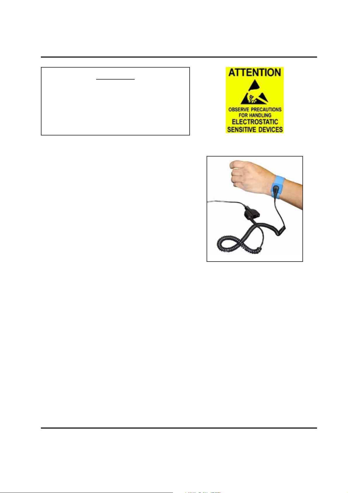
Electric Static Discharge (ESD) can damage or
destroy the hardware equipment used for the ATC200LITE-USB Teletilt
handling of equipment without the user feeling a shock.
The following precautions should be taken to prevent
ESD.
1. Wear an ESD wrist strap (Figure 1) and/or use a
test lead (ground), such as a single-wire conductor
with a series resistance of 1 megohm equipped with
alligator clips on each end. In using a ground, one
end of the alligator clip is connected to a grounded
equipment frame and the other end of the alligator
clip is touched with a bare hand.
2. Other precautions the user may take to reduce the
risk of ESD are:
• avoid wearing clothing that conducts static
electricity, such as wool
• remove all jewelry
• avoid handling equipment during an electrical storm
3. Before opening a package containing an electrostatic unit or an electrostatic sensitive device/
assembly, clip the free end of a test lead to the package. Leave the other end connected to the
equipment frame or other ESD ground. This will cause any static electricity which may have built
up on the package to discharge. Keep the unit package grounded during removal or placement of
equipment in the package.
4. Minimize handling of ESDS (Electric Static Discharge Sensitive) equipment. Keep replacement
equipment in the electrostatic-free packaging (with ground established between packaging and
equipment frame) until needed. Repairable ESD equipment should be placed in the electrostaticfree packaging (with ground connecting package to equipment frame) upon removal from ATC200LITE-USB system. ESD equipment should only be transported and stored in ESD protective
packaging.
5. Always avoid unnecessary movement of body, such as scuffing feet across flooring, when handling
ESDS equipment. Such movement will generate additional charges of static electricity.
®
System. ESD can occur during
Figure 1. ESD Wrist Strap.
Bulletin 639536 • Revision L October 2014 iii
Page 6

ATC200-LITE-USB Teletilt® RET System
6. When removing or replacing ESDS equipment, hold the device or assembly through the electrostatic-free wrap, where possible. If this is not possible, lift the device or assembly by its body only.
Do not touch component leads, connector pins, or any other electrical connections or paths, even
though they are covered by conformal coating.
7. Do not allow ESDS equipment to come in contact with clothing or other ungrounded materials
that may have an electrostatic charge. Charges on non-conductive material are not equal. For
instance, a plastic storage bag may have a –10,000 volt potential 1/2 inch from a +15,000 volt
potential with many such charges all over the bag. Do not hand ESD equipment to another person
until it is safely packaged for protection for ESD.
8. When moving ESDS equipment, always touch the surface on which it rests with bare skin for at
least one second before lifting. Before setting it on any surface, touch the surface with your free
hand for at least one second. Contact with bare skin provides a safe discharge path for charges
accumulated while you are moving around.
9. While servicing equipment containing ESD devices, do not handle or touch materials such as
plastic, vinyl, synthetic textiles, polished wood, fiberglass, or similar items that can generate static
charges; unless you repeat the grounding process with bare hands after contacting these materials.
10. Where possible, avoid repairs that require soldering at the equipment level. Soldering irons must
have heater/tips assemblies that are grounded to an electrical ground. Do not use standard plastic
solder suckers (special antistatic solder suckers are commercially available).
11. Ground the leads of test equipment momentarily before you energize the test equipment and
before you probe ESD devices or assemblies.
12. Work benches used for setting ESDS equipment should have ESD protective work surfaces.
These work benches should also have personnel ground straps. These straps prevent discharge of
static electricity from personnel handling ESDS items on the work bench surface. The work bench
surface should be connected to a ground through a ground cable. The resistance in the bench
top ground cable should be located at or near the point of contact with the top of the work bench.
The resistance should be high enough to limit any leakage current to 5 milliamperes or less. This
takes into consideration the highest voltage source within reach of grounded people and all the
parallel resistances to ground, such as wrist ground straps, table tops, and conductive flooring.
iv October 2014 Bulletin 639536 • Revision L
Page 7

Table of Contents
Revision History ....................................................................................................i
Notices and Precautions ........................................................................................ ii
Part 1 – Initial Setup
Section 1 Program Installation ..........................................................................1-1
1.0 System Requirements/Recommendations ................................................................. 1-1
1.1 Program Download and Installation ........................................................................... 1-1
Section 2 Controller Setup ................................................................................2-1
2.1 System Description ....................................................................................................2-1
2.2 Controller Communication ..........................................................................................2-2
2.3 Controller Setup .........................................................................................................2-3
2.4 Program Startup ......................................................................................................... 2-7
Part 2 – Uploading Firmware
Section 3 Uploading Firmware .......................................................................... 3-1
3.0 Overview ....................................................................................................................3-1
3.1 Installing Firmware Updates to Actuators ................................................................... 3-1
3.2 Installing Firmware Updates to TMA devices ............................................................. 3-2
3.3 Updating the Antenna Definition File .......................................................................... 3-5
3.4 Specifying an Antenna Definition File ......................................................................... 3-5
Part 3 – Device Discovery for All Types of Antennas
Section 4 Device Discovery and Addressing ...................................................... 4-1
4.1 Device Search .......................................................................................................... 4-1
4.2 Device Information Views ......................................................................................... 4-5
4.2.1 All Devices View ....................................................................................................... 4-5
4.2.2 RET Devices View .................................................................................................... 4-6
4.2.3 TMA Devices View .................................................................................................... 4-7
4.3 Addressing ................................................................................................................ 4-8
Bulletin 639536 • Revision L October 2014 v
Page 8

Table of Contents ATC200-LITE-USB Teletilt® RET System
Part 4 – Operating Instructions for Standard Antennas
with Attached Actuators
Section 5 Actuator Protocol Mode Switching....................................................5-1
5.0 Protocol Mode switching for ATM3 devices .............................................................. 5-1
5.0.1 Using AISG Reset Option Tools ............................................................................... 5-1
5.0.2 Switching a Single ATM200-002 to Ericsson Protocol .............................................. 5-4
5.1 Protocol Mode switching for AccuRET devices ........................................................ 5-6
Section 6 Device Configuration ........................................................................6-1
Section 7 Changing the Electrical Downtilt on a Single Antenna ......................7-1
Section 8 Changing the Electrical Downtilt on a Group of Antennas ................ 8-1
Part 5 – Operating Instructions for Antennas with Multiple
Integrated Actuators
Section 9 Switching Operating Modes for Multiple Integrated Actuators ........ 9-1
Section 10 Device Configuration for Antennas with Multiple Integrated
Actuators ..................................................................................... 10-1
Section 11 Adjusting the Electrical Downtilt on a Single Antenna Equipped
with Multiple Integrated Actuators ............................................... 11-1
Section 12 Adjusting the Electrical Downtilt on a Group of Antennas Equipped
with Multiple Integrated Actuators ............................................... 12-1
Part 6 – Operating Instructions for SmartBeamTM Antennas
Section 13 Device Configuration with SmartBeam™ Antennas ......................13-1
Section 14 Changing the Electrical Downtilt on a Single SmartBeam™
Antenna ........................................................................................14-1
Section 15 Changing the Boresight (Pan) on a Single SmartBeam™
Antenna ........................................................................................15-1
TM
Section 16 Changing the Beamwidth (Fan) on a Single SmartBeam
..................
Antenna ........................................................................................16-1
Section 17 Changing the Electrical Downtilt on a Group of SmartBeam™
Antennas .......................................................................................17-1
vi October 2014 Bulletin 639536 • Revision L
ii October 2014 Bulletin 639536 • Revision L
Page 9

ATC200-LITE-USB Teletilt® RET System Table of Contents
Part 7 – Saving Reports and Retrieving Alarm Status
Section 18 Saving a Site Report or Site Configurations ...................................18-1
18.1 Saving/Viewing a Site Report Formatted to Open in Word ..................................... 18-1
18.2 Saving/Viewing a Site Report Formatted to Open in Excel ..................................... 18-4
Section 19 Device Test, Alarm Status, and Device Information ...................... 19-1
19.1 Obtaining Device Information .................................................................................. 19-2
19.2 Retrieving Current Alarm Status .............................................................................. 19-2
19.3 Clearing All Alarms on a Device ..............................................................................19-3
19.4 Executing a Self Test Movement for a Device ......................................................... 19-3
Section 20 Alarm Status for TMA ..................................................................20-1
20.1 Alarm Reported by TMA ..........................................................................................20-1
20.2 Retrieving Current Alarm from TMA ........................................................................20-3
20.3 Clearing All Alarms on TMA ..................................................................................... 20-4
Part 8 – Operating Instructions for Tower Mounted Amplifiers (TMA)
Section 21 Device Configuration with TMA ................................................... 21-1
Section 22 Changing the Gain on a Variable-Gain TMA ................................ 22-1
Section 23 Changing the Operating Mode on a TMA .....................................23-1
Part 9 – Appendix
Appendix A Letter of Compliance.................................................................... A-1
Appendix B Declaration of Conformity ............................................................ B-1
Site Configuration Worksheet ........................................................ (Tear Out Page)
Bulletin 639536 • Revision L October 2014 vii
Page 10

Table of Contents ATC200-LITE-USB Teletilt® RET System
This page intentionally left blank.
viii October 2014 Bulletin 639536 • Revision L
Page 11

Part 1
Initial Setup
Bulletin 639536 • Revision L October 2014
Page 12

Part 1–Initial Setup ATC200-LITE-USB Teletilt® RET System
This page intentionally left blank.
October 2014 Bulletin 639536 • Revision L
Page 13
Section 1
Program Installation
The controller MUST remain disconnected from the computer and its power
supply during the ATC Lite software installation process.
1.0 System Requirements/Recommendations
Required: • Windows® 2000 or XP operating systems, or newer
• Available working USB port (USB1.1 or USB2.0)
Recommended: • Screen resolution of 1024 x 768, or higher
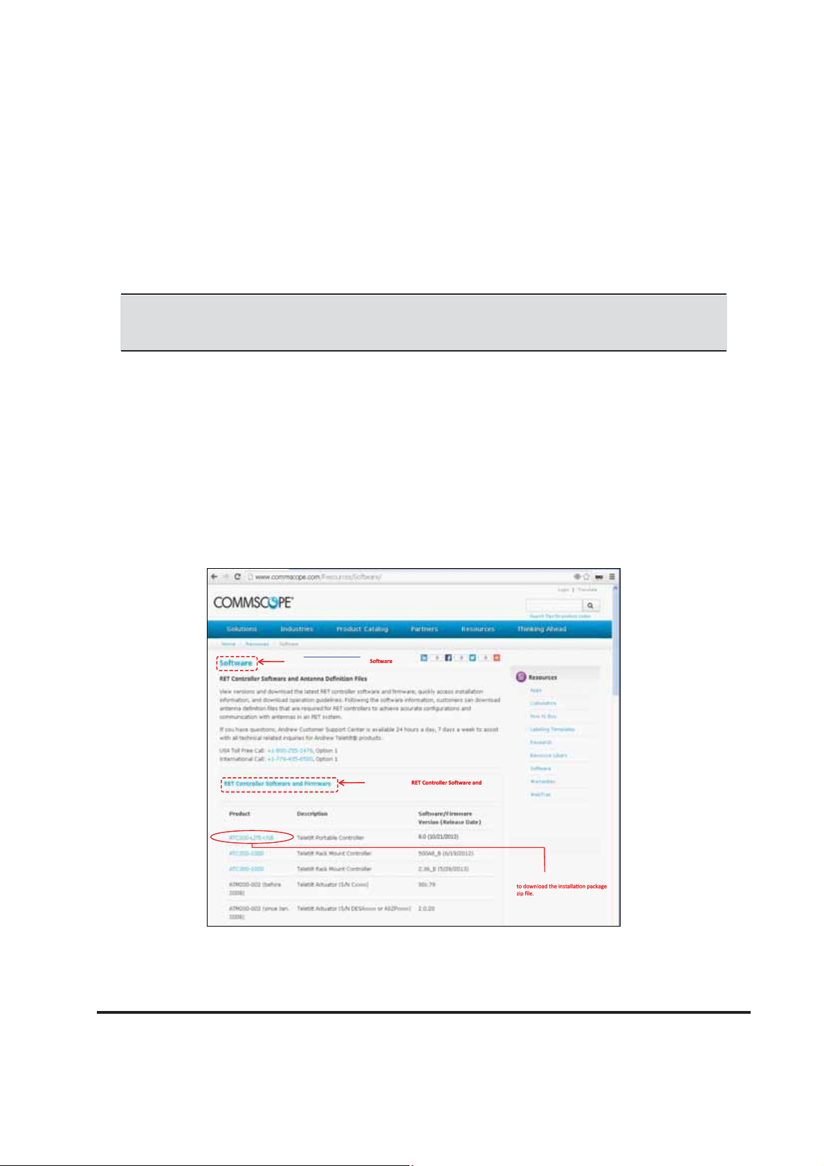
1.1 Program Download and Installation
If you are upgrading the ATC Lite software from an earlier installed version, it is recommended that
the earlier version is uninstalled before the new version is installed. Download the ATC Lite software
zip file.
From www.commscope.com click on Resources
From www.commscope.com click on Resources
Resourc e Library, then click on ‘
Resourc e Library, then click on ‘
the right side pane ‘Resources’ to view this page.
the right side pane ‘Resources’ to view this page.
’ link on
’ link on
Click on this link ‘
Click on this link ‘
Firmware’ to view the list of downloads as shown
Firmware’ to view the list of downloads as shown
here.
here.
Click on this link ‘ATC200-LITE-USB’
Click on this link ‘ATC200-LITE-USB’
Figure 1-1. Downloading ATC Lite Software.
Microsoft, Encarta, MSN, and Windows are either registered trademarks or trademarks of Microsoft Corporation in the United States
and/or other countries.
Bulletin 639536 • Revision L October 2014 1-1
Page 14
Section 1–Program Installation ATC200-LITE-USB Teletilt® RET System
1. Download the ATC Lite software zip file. From the www.commscope.com click on the Re-
sources drop down and then on RESOURCE LIBRARY link, then select the link Software on
the right side pane named Resources. In the Software page click on the link RET Controller
Software and Firmware to view the download list.
Select the ATC200-LITE-USB link to download the installation zip file (See Figure 1-1).
2. This zip file can be placed in any directory on the PC’s local C:\ drive. Double-click on the zip file
to extract the ATC Lite setup file and its supporting installation documentation.
Do not connect the ATC200-LITE-USB controller to the computer at anytime during
the software installation process.
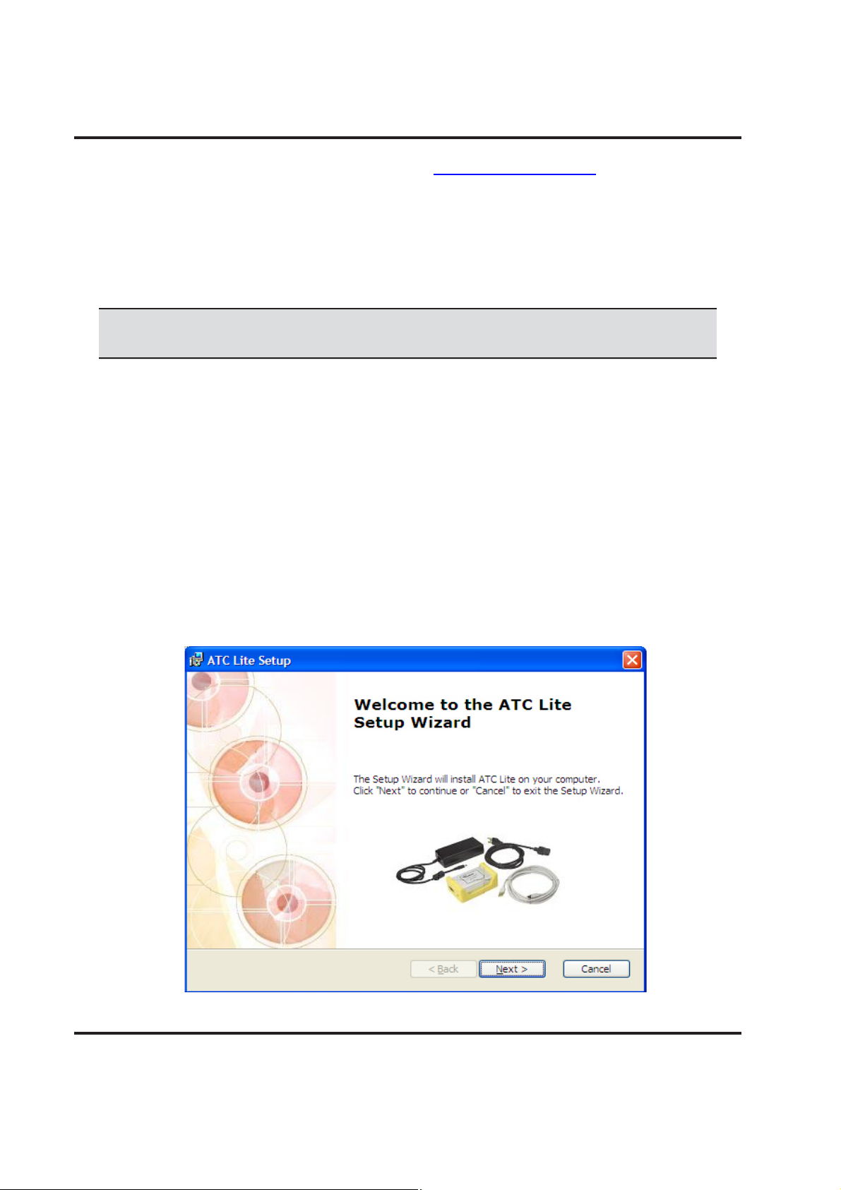
3. Double click on the setup file (eg. ATCLite80Setup.msi) to begin the installation process. Note
that the number shown in the filename represents the software release version.
During the program installation process, a single antenna definition file and additional support
files will self-extract into the same directory with the program file, and a program icon will be
placed on the computer’s desktop. The antenna definition file provides the program with an
updated drop down list of antennas compatible with the ATC200-LITE-USB controller. Tilt
parameters for each antenna are included in the antenna definition file to show the tilt range
for each antenna and to communicate instructions to the antenna/actuator when tilt adjustments
are made from the controller. Latest firmware files for Tower Mounted Amplifiers (TMA) and USB
driver files are available
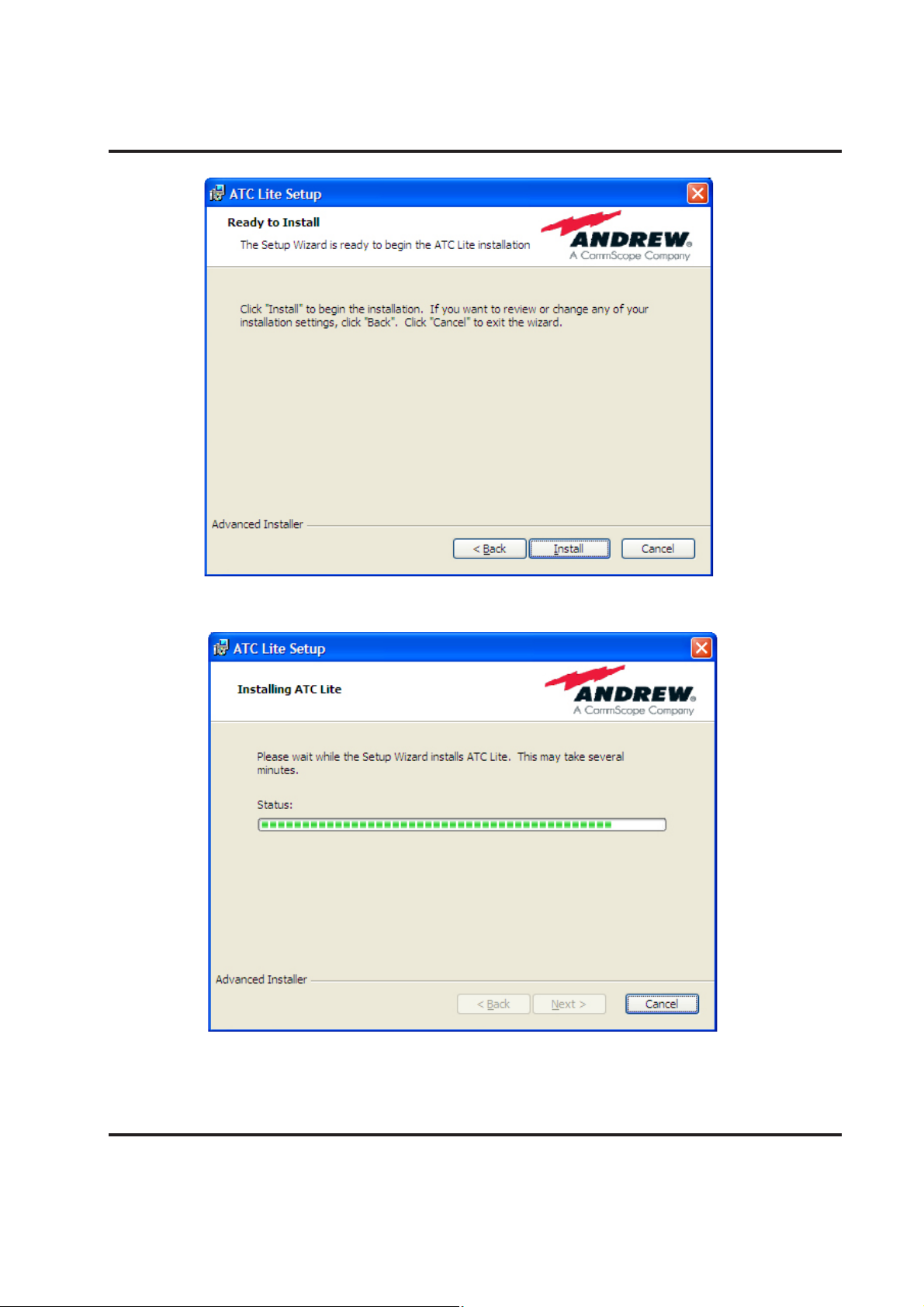
4. Follow the on-screen prompts, as shown in Figures 1-2 through 1-5.
5. This installation process automatically installs the relevant USB drivers (32 bit or 64 bit) for con
necting the ATC200-Lite-USB device through USB connection. Proceed to Section 2.3, Control
ler setup for further instructions for connecting using serial or USB.
Figure 1-2. ATC Lite Software Setup Wizard.
1-2 October 2014 Bulletin 639536 • Revision L
Page 15
ATC200-LITE-USB Teletilt® RET System Section 1–Program Installation
Figure 1-3. ATC Lite Software setup.
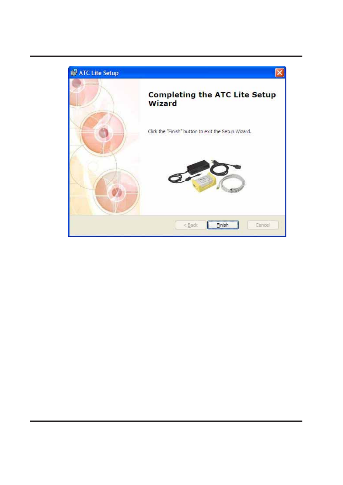
Figure 1-4. Status for ATC Lite Software Installation.
Bulletin 639536 • Revision L October 2014 1-3
Page 16
Section 1–Program Installation ATC200-LITE-USB Teletilt® RET System
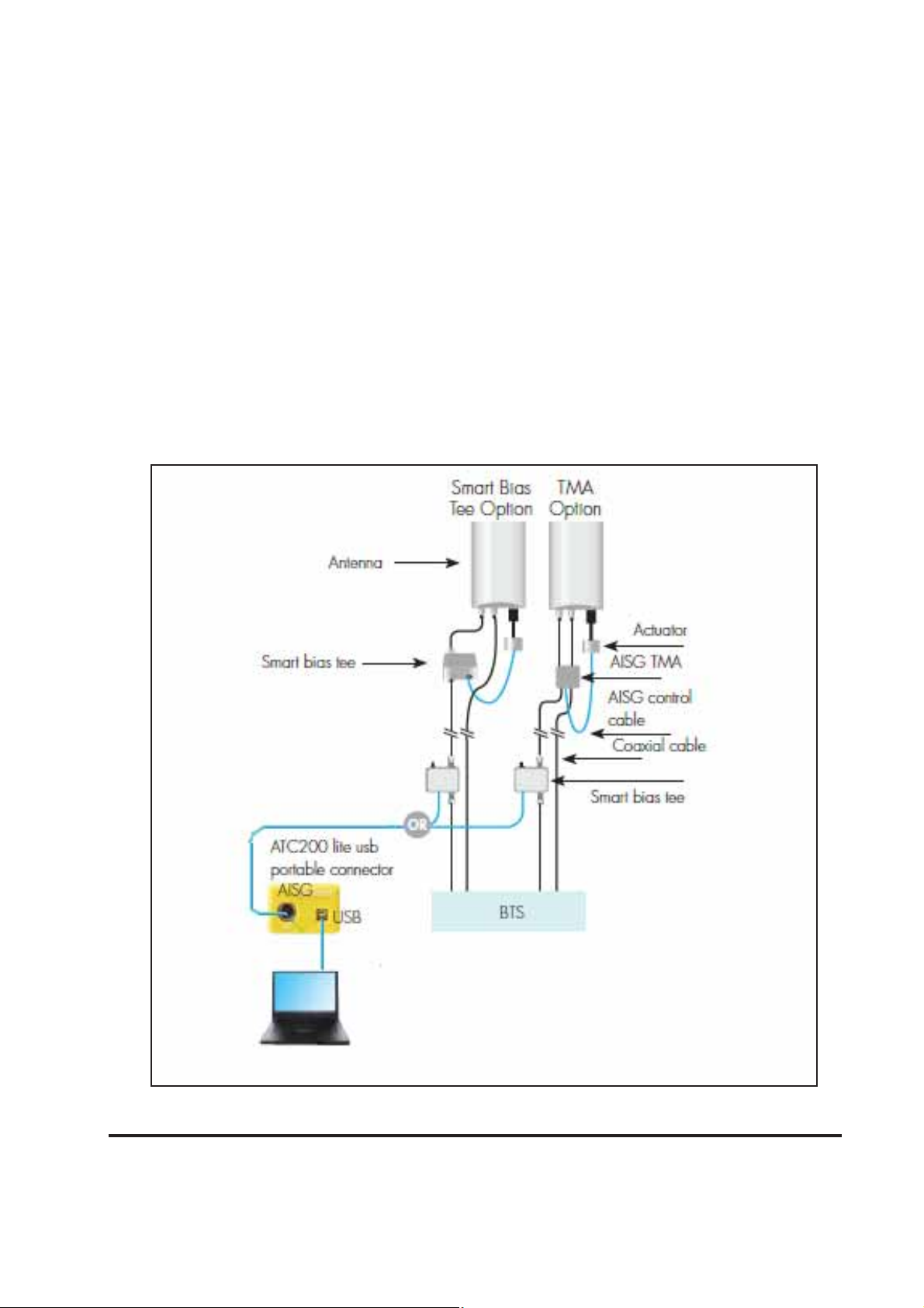
Figure 1-5. Completing ATC Lite Software Installation.
1-4 October 2014 Bulletin 639536 • Revision L
Page 17

ATC200-LITE-USB Teletilt® RET System Section 1–Program Installation
This page intentionally left blank.
Bulletin 639536 • Revision L October 2014 1-5
Page 18
Section 2
Controller Setup
2.1 System Description
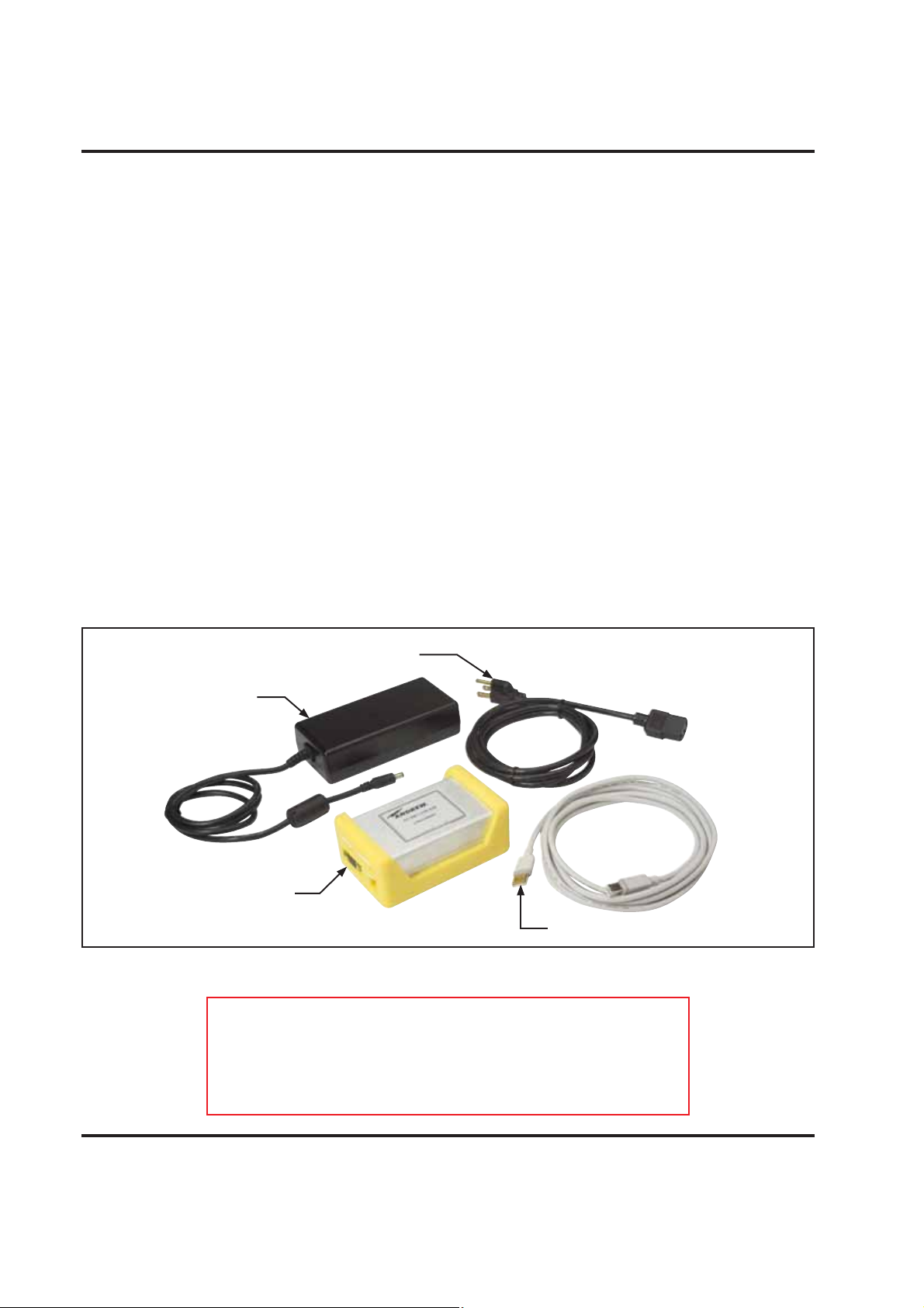
The ATC200-LITE-USB is an antenna system controller that is used within the Andrew Teletilt® RET
system to manage electrical tilt settings of an antenna(s) remotely. Figure 2-1 shows an example of
components used in an ATC200-LITE-USB Teletilt system. Follow the procedures described in the
installation bulletins included with each component for successful installation for each device.
Figure 2-1. Example of Andrew Teletilt® Basic RET System with an ATC200-LITE-USB.
2-1 October 2014 Bulletin 639536 • Revision L
Page 19
ATC200-LITE-USB Teletilt® RET System Section 2–Controller Setup
It is recommended that each actuator be connected to the controller while on the ground and
tested for proper function. The following site antenna/actuator information should be recorded
before the antennas are installed on the tower:
• The serial number for each actuator
• The antenna type (model number) in which the actuator will be operating
• The location the antenna will be positioned at on the tower site
This will assist in configuring the controller to manage tilt operations successfully for each actuator.
A site configuration worksheet is provided at the end of this manual to record the antenna/actuator
information.
2.2 Controller Communication
The controller serves as an interface between a local PC/laptop and the ATM200 RET actuator/
antenna system. The ATC200-LITE-USB controller provides signal level conversion from a PC to
RS–485 (used in the ATM200 actuators), as well as power to the ATM200 actuators that are attached to the antennas. LEDs on the controller are used to indicate power and data communication.
The ATC200-LITE-USB controller is equipped with a USB port, as well as a RS–232 serial port for
flexibility in connecting to a PC. See Figures 2-2 and 2-3.
Note that although data is stored in the actuator, it can not be saved in the controller. All site
information can be saved on the PC (see Section 13).
dc Power Converter
Power Cord
ATC200-LITE-USB
Controller
DISCONNECT THE ATC200-LITE-USB CONTROLLER FROM THE
RET SYSTEM AT THE END OF EACH SESSION TO PREVENT
POSSIBLE DAMAGE TO RET DEVICES.
Power Cord
USB Cable
Figure 2-2. ATC200-LITE-USB Controller Kit.
IMPORTANT
Bulletin 639536 • Revision L October 2014 2-2
Page 20
Section 2–Controller Setup ATC200-LITE-USB Teletilt® RET System
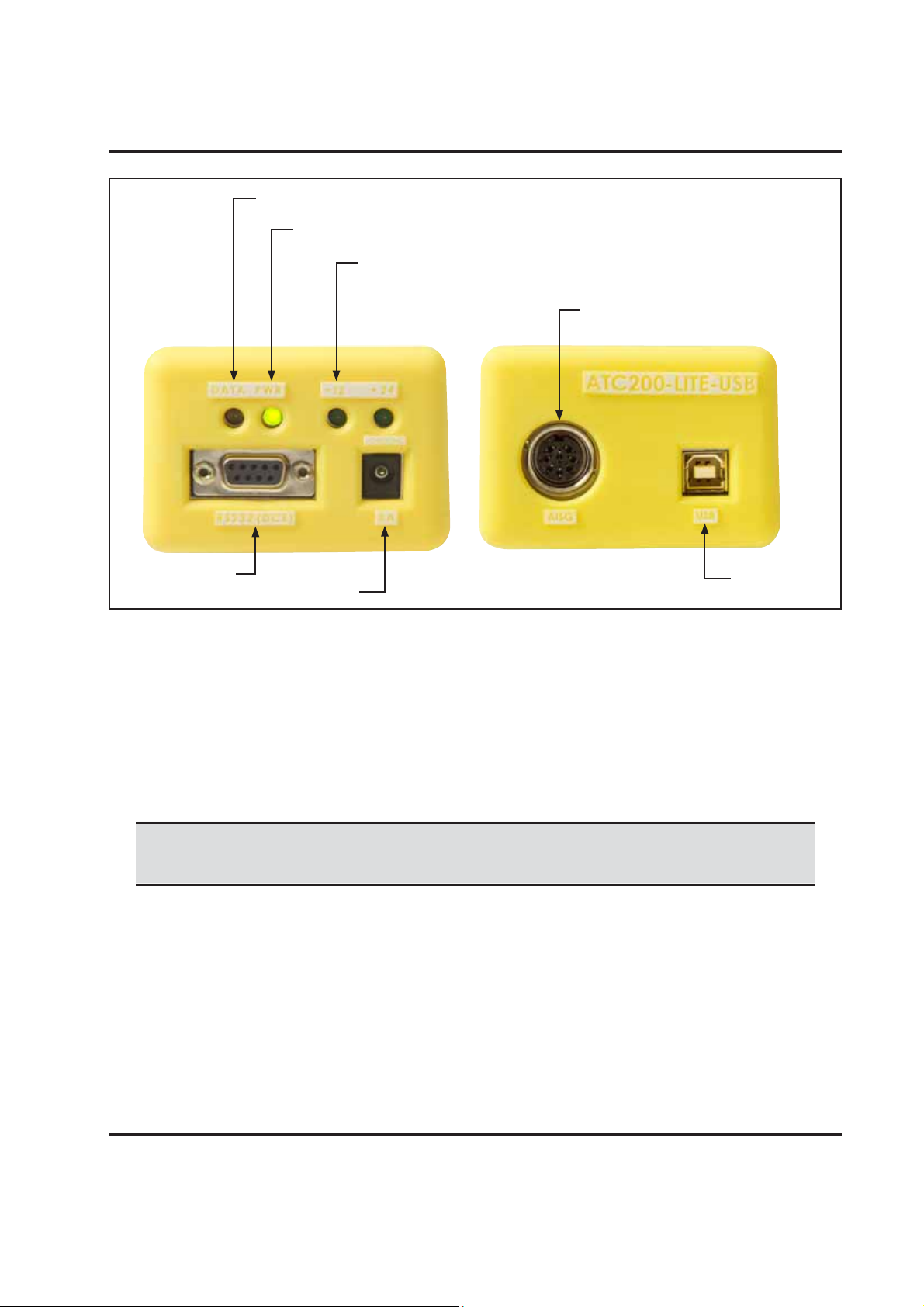
Data LED flashes green on transmitting and red on receiving signals.
Power LED is green when power is input.
+12 and +24 LEDs are lit to show voltage level output.
AISG female port for
control cable from antenna.
RS-232
Serial Port
dc IN Port
Figure 2-3. ATC200-LITE-USB Controller End Panels.
USB Port
2.3 Controller Setup
Connect the supplied 24 Vdc power converter to the dc IN port on the controller (Figure 2-3).
Verify that the PWR LED turns green.
1. Using a USB Connection
• Connect the supplied USB cable between the controller and the PC. See Figure 2-3 for port
connections on the controller.
The first time you connect a given ATC200-LITE-USB controller to a given local
computer, the drivers will be loaded automatically for the USB connection.
• If you are prompted to locate/install the USB driver for the new device found, then the drivers
failed to install during the installation process.
Proceed as given below.
• Follow the steps shown in Figures 2-4 through 2-6 to successfully install the USB driver for the
ATC200-LITE-USB controller.
• See paragraph 2.4 to launch the ATC Lite program and view the USB port assignment.
Microsoft, Encarta, MSN, and Windows are either registered trademarks or trademarks of Microsoft Corporation in the United States
and/or other countries.
2-3 October 2014 Bulletin 639536 • Revision L
Page 21
ATC200-LITE-USB Teletilt® RET System Section 2–Controller Setup
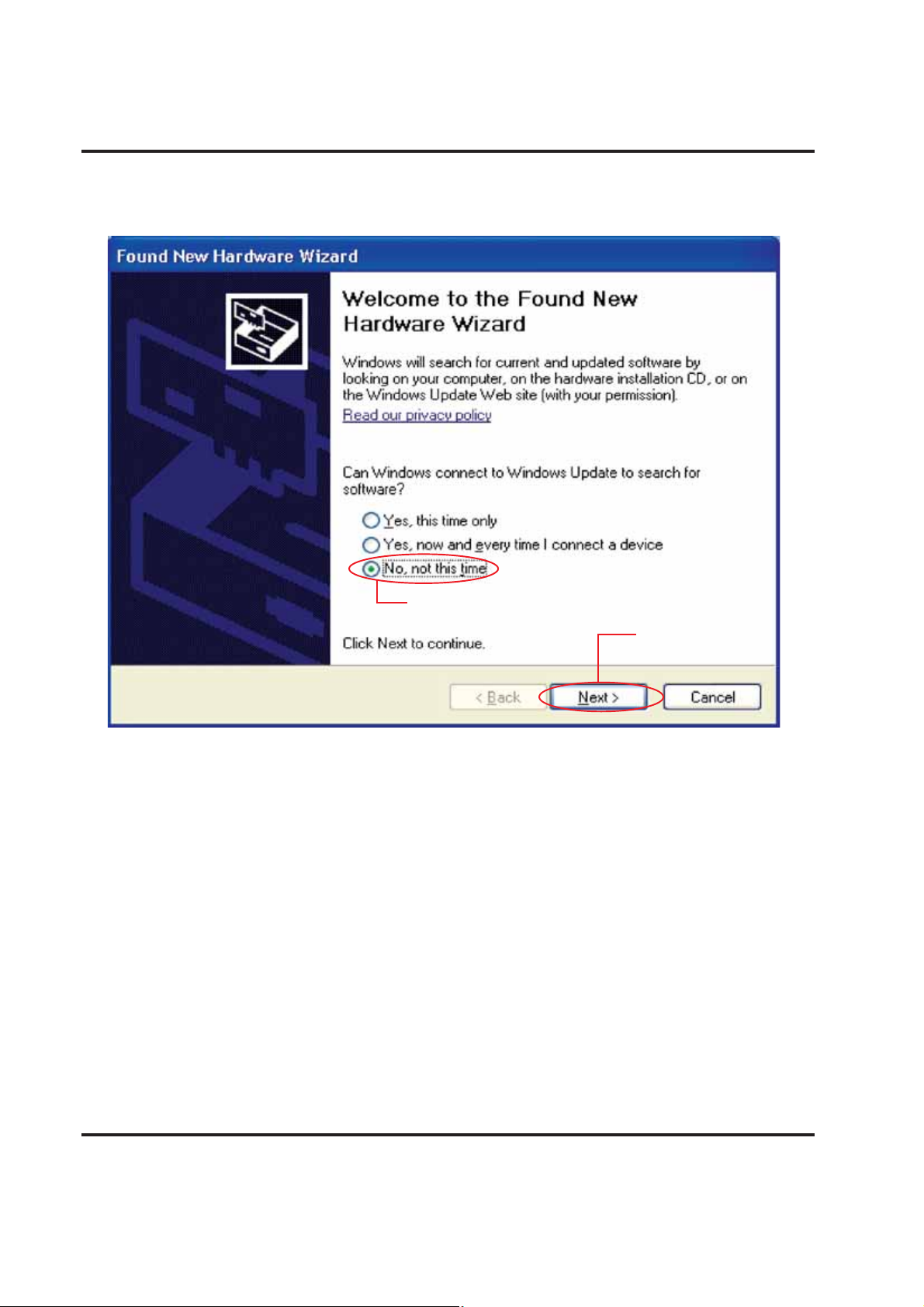
1. Select No, not this time.
Figure 2-4. Notification When New Hardware Is Found.
2. Click on Next.
Bulletin 639536 • Revision L October 2014 2-4
Page 22

Section 2–Controller Setup ATC200-LITE-USB Teletilt® RET System
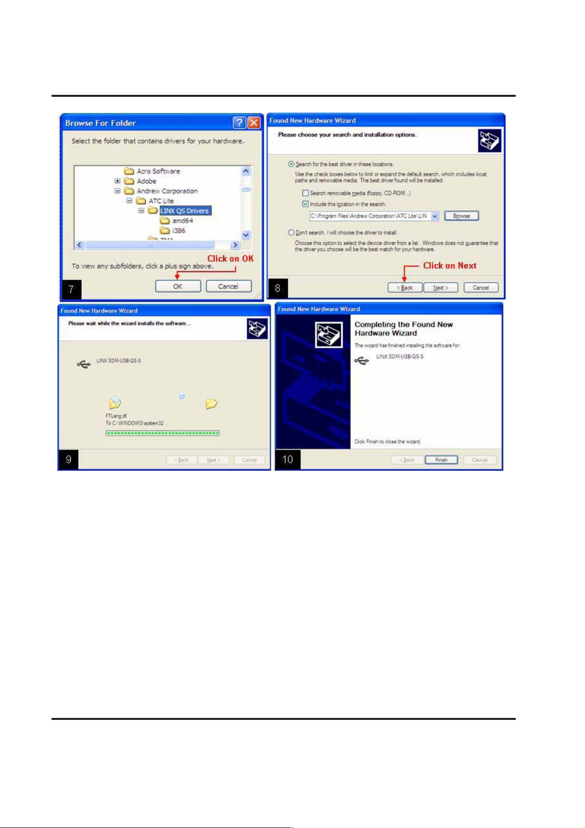
Figure 2-5. Locating the ATC Lite Directory.
2-5 October 2014 Bulletin 639536 • Revision L
Page 23
ATC200-LITE-USB Teletilt® RET System Section 2–Controller Setup
Figure 2-6. Installing USB Driver.
Bulletin 639536 • Revision L October 2014 2-6
Page 24
Section 2–Controller Setup ATC200-LITE-USB Teletilt® RET System
2.4 Program Startup
Connect the desired length RET control cable be-1.
tween the controller’s AISG connector and the first
device in the RET system (or actuator that is to be
tested before the antenna is mounted on the tower).
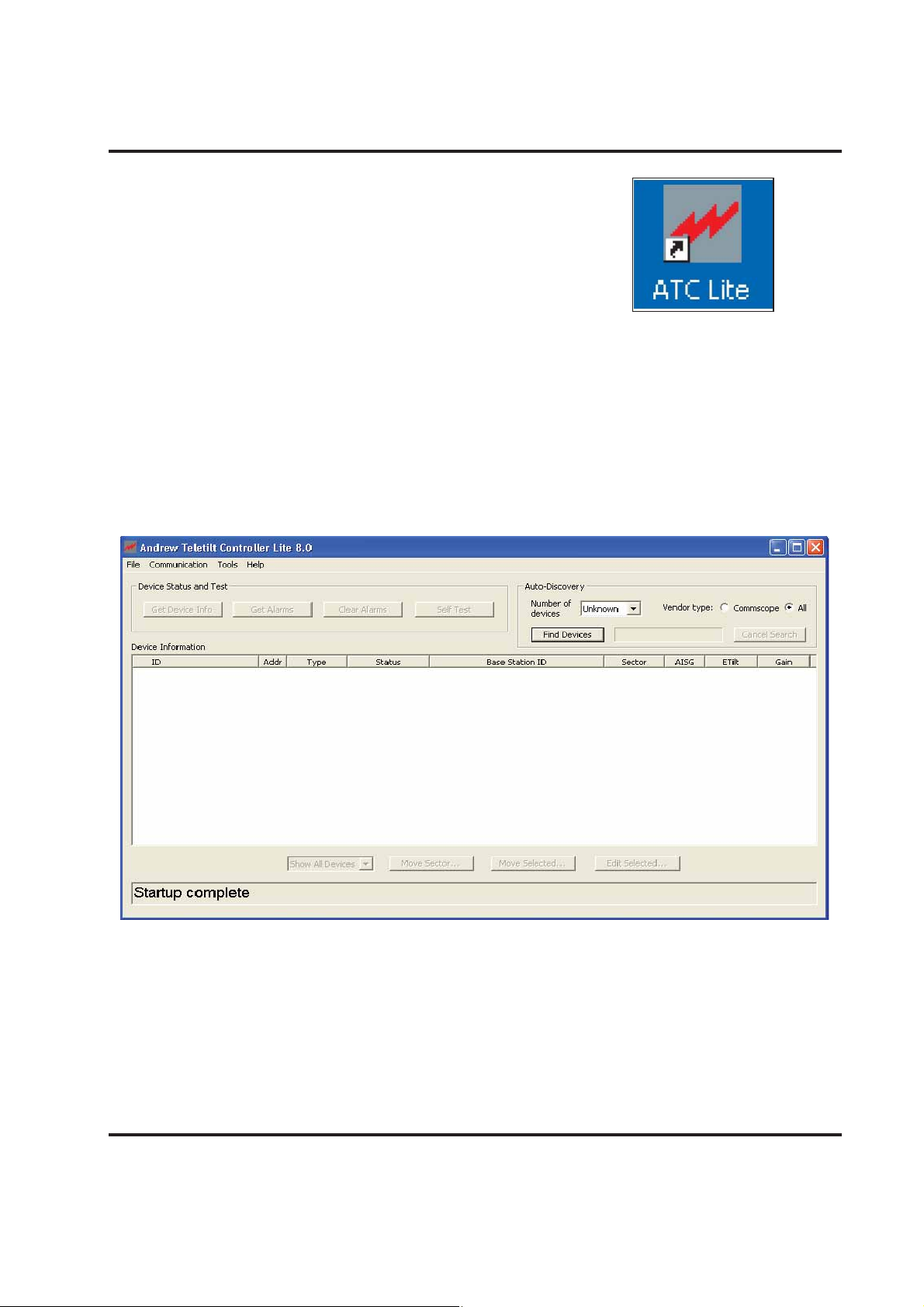
Double-click on the ATC Lite icon that was placed on 2.
the computer’s desktop during program installation
(Figure 2-8).
The controller program will open to its main screen (Figure 2-9).3.
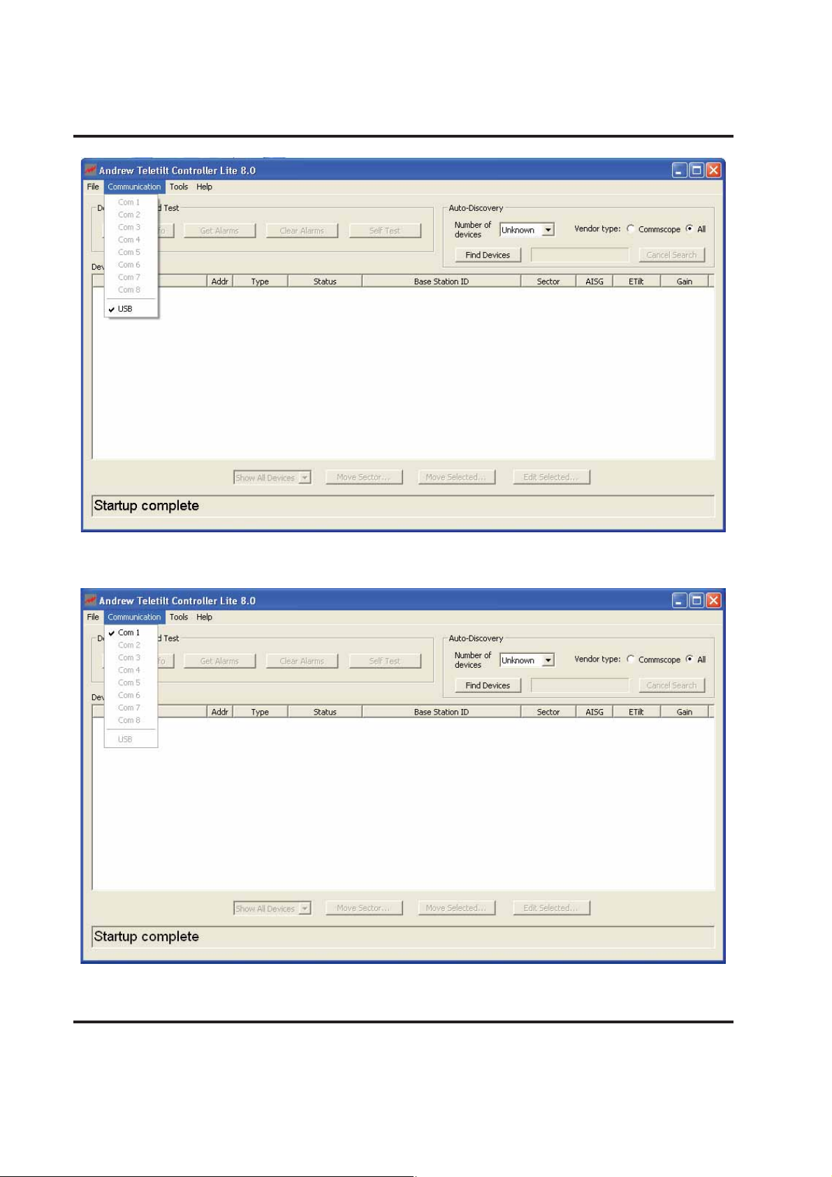
Select 4. Communication from the main menu to view the communication port used for the connection. See Figures 2-10 and 2-11 for examples.
If you desire to exit the program at this time, select 5. File
X in the far top right.
→Exit from the main menu or click on the
Figure 2-8. ATC Lite Program Icon.
Figure 2-9. ATC Lite Program Main Screen.
2-7 October 2014 Bulletin 639536 • Revision L
Page 25
ATC200-LITE-USB Teletilt® RET System Section 2–Controller Setup
Figure 2-10. USB Port Connection Shown.
Figure 2-11. COM Port (Serial) Connection Shown.
Bulletin 639536 • Revision L October 2014 2-8
Page 26

Section 2–Controller Setup ATC200-LITE-USB Teletilt® RET System
This page intentionally left blank.
2-9 October 2014 Bulletin 639536 • Revision L
Page 27

Part 2
Uploading Firmware
Bulletin 639536 • Revision L October 2014
Page 28

Part 2–Uploading Firmware ATC200-LITE-USB Teletilt® RET System
This page intentionally left blank.
October 2014 Bulletin 639536 • Revision L
Page 29
Section 3
Uploading Firmware
3.0 Overview
Firmware files for the Andrew Teletilt controller and antenna definition file can be downloaded from
Software web page on the web site
SOURCE LIBRARY link, then select the link Software on the right side pane named Resources.
In the Software page click on the link RET Controller Software and Firmware to view the download list and from this select link ATC200-LITE-USB or ATClite v8.0 Software to download the zip
for installation.
Note: See Section 1 for installing upgrades to the ATC Lite program.
3.1 Installing Firmware Updates to Actuators
Firmware updates are occasionally made. Actuators are upgraded following a device scan when the
newer version firmware is available.
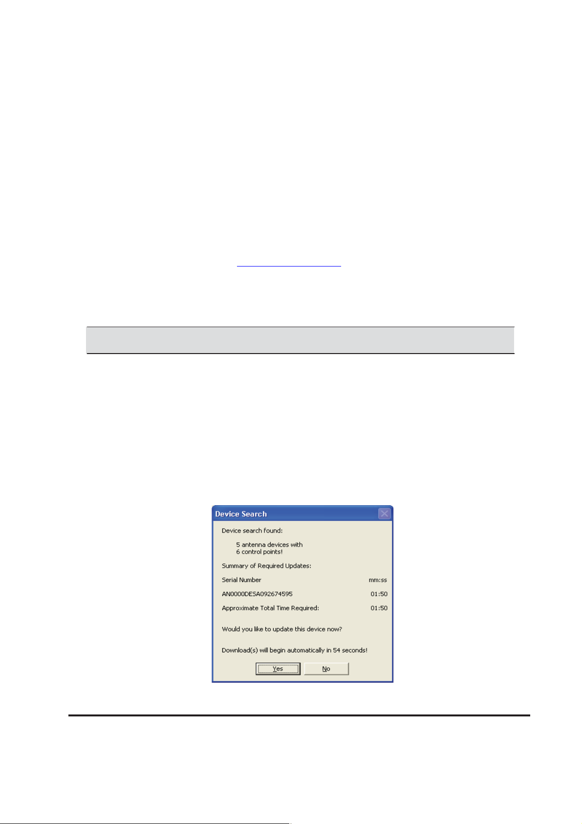
Download Phase is new way to install firmware updates. The actuator update status box appears
at the end of the first device search (Figure 3-1). Once the updates are made, this status box is not
seen again, until new actuator updates are made available.
If any of the actuators require updates, they are listed by serial number and the time needed for
installation. Click Yes to confirm updates. If no action is taken, downloads will begin automatically
within 60 seconds.
www.commscope.com, by Clicking on the Resources →RE-
Figure 3-1. Starting Download Phase.
Bulletin 639536 • Revision L October 2014 3-1
Page 30
Section 3–Uploading Firmware ATC200-LITE-USB Teletilt® RET System
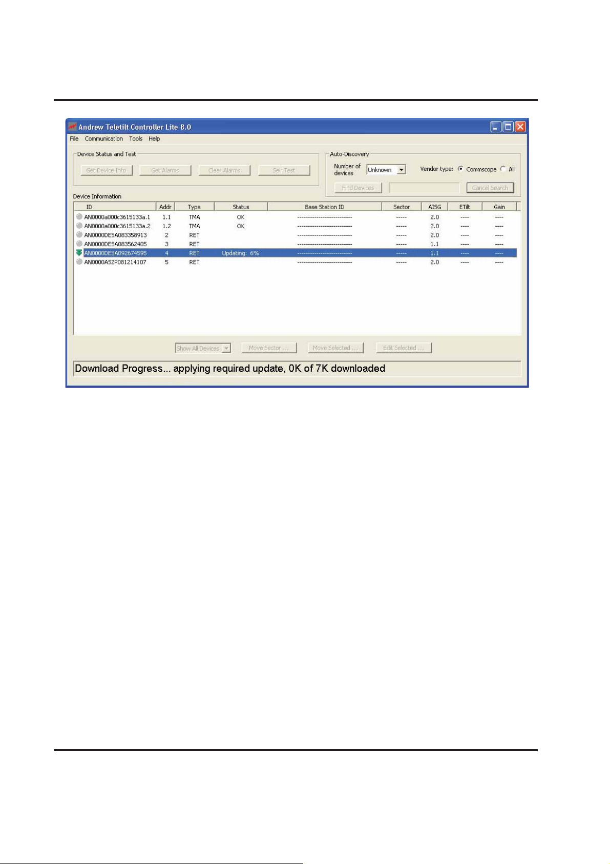
Figure 3-2. Applying Firmware Update .
Firmware updates were placed in the C\:Program Files\Andrew Corporation\ATC Lite directory of
the computer when the ATC Lite Setup file is run.
3.2 Installing Firmware updates to TMA devices
Firmware updates are occasionally made to TMA devices. TMA firmware is upgraded by selecting
the device from the list following a device scan.
Select the TMA device from list, then right click to view the menu ‘Start firmware update…’ and click
or press ENTER to initiate the update. The TMA device that is selected for update is listed with serial number and time needed for update. Click on Yes in the “TMA device firmware update” dialog to
proceed with the firmware update (Figure 3-4).
3-2 October 2014 Bulletin 639536 • Revision L
Page 31

ATC200-LITE-USB Teletilt® RET System Section 3–Uploading Firmware
Select TMA, right click and then
click on ‘
…’
Figure 3-3. Initiate firmware upgrade for TMA device.
Click on ‘Yes’ to
start Firmware
upgrade
Figure 3-4. Starting TMA firmware update.
Bulletin 639536 • Revision L October 2014 3-3
Page 32

Section 3–Uploading Firmware ATC200-LITE-USB Teletilt® RET System
Figure 3-5. Firmware update in progress.
Select TMA, right click menu
updated to the latest version
Figure 3-6. Firmware update status
After successful completion of firmware update the right click on the TMA display “Firmware is upto-date” indicates that the firmware on TMA is updated to the latest version provided with ATC Lite.
Firmware updates for TMA were placed in the C:\Program Files\Andrew Corporation\ATC Lite\TMA
directory of the computer when the ATC Lite setup file is run.
3-4 October 2014 Bulletin 639536 • Revision L
Page 33

ATC200-LITE-USB Teletilt® RET System Section 3–Uploading Firmware
3.3 Updating the Antenna Definition File
The antenna definition file is automatically placed in the C:\Program Files\Andrew Corporation\
ATC Lite directory of the computer when the ATC Lite Setup file is run. The latest version of the
antenna definition file can be separately downloaded from the Commscope website at www.commscope.com (Select Resources -> RESOURCE LIBRARY ->Software->Antenna Definition Files).
After the file has been downloaded, double-click on the zip file (e.g. Andrew_Self-Extracting.
zip) to extract the self-installer files available in the folder Andrew_Self-Extracting (e.g. RET-ANAT_057_msi.msi and ACRET1-TABLE_005.msi). Double-click on the extracted self-installer file to
have the antenna definition file automatically placed in the ATC Lite directory.
During program startup, the ATC200-LITE-USB controller will look in the ATC Lite directory for the
latest Andrew antenna definition file and automatically load it into the program. Note that if an updated antenna definition file has been placed in the ATC Lite directory while the ATC Lite program
is launched, the program will need to be exited and restarted to recognize the new file.
3.4 Specifying an Antenna Definition File
Although the ATC Lite program automatically defaults to use the latest version Andrew antenna
definition table file, earlier versions can be loaded by the controller. This may be necessary if the
latest antennna file does not list your Andrew antenna model. This feature also provides to load
antenna definition table for Andrew AccuRET devices.
1. To select a different antenna definition file, go to Tools
the top of the screen (Figure 3-7).
2. Click on the drop down list arrow to select the desired antenna definition file from the list (Figure
3-8) for ATM200 and AccuRET devices respectively.
3. Click Load File to load the selected antenna definition files for (Figure 3-8) ATM200 and Accu-
RET devices. Status of loading the files will be displayed in the Com-mand Status/Response
window.
4. Click Close after the antenna definition files have been loaded successfully.
→Antenna Files from the main menu at
Bulletin 639536 • Revision L October 2014 3-5
Page 34

Section 3–Uploading Firmware ATC200-LITE-USB Teletilt® RET System
ė
feature can be used to upload earlier
to upload Go to Tools Antenna Files
Figure 3-7. Selecting Antenna Files from the Main Menu.
Figure 3-8. Antenna Definition Files Drop Down List.
3-6 October 2014 Bulletin 639536 • Revision L
Page 35

ATC200-LITE-USB Teletilt® RET System Section 3–Uploading Firmware
This page is intentionally left blank.
Bulletin 639536 • Revision L October 2014 3-7
Page 36

Part 3
Device Discovery for All
Types of Antennas
October 2014 Bulletin 639536 • Revision L
Page 37

ATC200-LITE-USB Teletilt® RET System Part 3–Device Discovery for All Types of Antennas
This page intentionally left blank.
Bulletin 639536 • Revision L October 2014
Page 38

Section 4
Device Discovery and Addressing
4.1 Device Search
A device search is required in order for the program to determine which devices are present on the
tower and to retrieve their current configuration parameters. It is important to note that this feature
automatically scans and sets each device address to ‘0’ and then readdresses them in the order
that they respond to the controller during the device search. Generally, the devices respond in
sequential order of their serial number. This feature helps reduce possible conflict issues that could
arise during operation later. The device search is controlled by number of devices and vendor type.
Initially the device search is set find all the devices available and only Commscope devices. Selecting number of devices for search can significantly reduce the time to complete device search.
Any actuator having an earlier version firmware than used by the controller will be updated after the
device search (see Section 3). Firmware update for TMA devices can be carried out manually after
the device search (see Section 3).
1. From the program’s main startup screen, click Find Devices to start the device search
(Figure 4-1).
Click on Find Devices.
Figure 4-1. Main Startup Screen Ready for Device Search.
4-1 October 2014 Bulletin 639536 • Revision L
Page 39

ATC200-LITE-USB Teletilt® RET System Section 4–Device Discovery and Addressing
2. The Auto Discovery Bar (located at the top of the screen) and the Command Status/Re-
sponse window (located at the bottom of the screen) will show the progress/activity during
the search (Figure 4-2). As each device is found during the search, the Command Status/
Response window will show the status of how many devices have been found and the found
devices are displayed on screen. Number of devices can be selected for value from 1 to 32 for
specific number of devices or “Unknown” for all devices available. Vendor type selection can be
for Commscope devices only or all vendor devices including Commscope.
NOTE: The amount of time the device search takes is dependent upon the number of AISG
devices present on the tower. Typically, a device search for a tower site that contains a small
number of devices (e.g. 6) will take about 3 minutes. A device search for a tower site with a full
complement of devices may take up to 10 minutes.
The Cancel Search button can be used to halt the device search at anytime except during
Firmware downloads. Note that if a device search is halted, a new search can be started. To
start a new device search, click on Find Devices again (Figure 4-2). If a device search is
halted, the devices found will be displayed in the list and proceed to required firmware download followed by device information retrieval.
Auto Discovery Bar
shows progress
Command Status/Response window
Figure 4-2. Progress Shown During Device Search.
Bulletin 639536 • Revision L October 2014 4-2
Cancel search
Page 40

Section 4–Device Discovery and Addressing ATC200-LITE-USB Teletilt® RET System
3. At completion of the search, a notification will appear showing the number of devices found
(Figure 4-3). This example shows 5 devices and 7 total sub-devices (or control points) found.
Click OK. Devices found during the device search will be displayed in the main screen (Figure
4-4). The default view of the device list displaying device information is ‘Show All Devices’ as
shown Figure 4-4. See next section for details on device list views section.
Figure 4-3. Device Search Results.
Figure 4-4. The Main Screen Provides Configuration Data.
4-3 October 2014 Bulletin 639536 • Revision L
Page 41

ATC200-LITE-USB Teletilt® RET System Section 4–Device Discovery and Addressing
NOTE: If it is known that devices are present and operational, but none were found
by the device search, it is possible that the currently selected USB or serial port is not
communicating with the controller.
To check USB or serial port communication, repeat the device search and watch the
communication light shown on the data LED of the controller. It should blink rapidly
during the device search. If it does not, the USB or serial port currently selected may
not be functional. In this case, use the methods described in Section 4.2 to select a
different serial port and repeat the search until you see activity on the controller data
communication LED. If you are using a USB connection, close the program and verify
that the ATC200-LITE-USB driver is properly installed.
If attempts have been made on all available serial ports without success, contact your IT
department for assistance in determining the reason no serial port is available for use by
the program.
For any questions regarding the ATC200-LITE-USB or the ATC Lite software, please contact
our Customer Technical Support Center.
Available 24 hours a day, 7 days a week at the telephone numbers listed below.
• U.S.A.: (800) 279-8185
• International: (703) 726-5556
Bulletin 639536 • Revision L October 2014 4-4
Page 42

Section 4–Device Discovery and Addressing ATC200-LITE-USB Teletilt® RET System
4.2 Device Information Views
4.2.1 All Devices View
The ‘Show All Devices’ device information view displays the main information about the device
found. This view also displays device specific information like Current tilt for RET device and Gain
value for TMA devices (Figure 4-5). Views of the device information list is switched between ‘Show
All Devices’, ‘Show RETs’ and ‘Show TMAs’ by using drop down list (Figure 4-6).
Relevant actions for devices like Tilt Move, Tilt Move for Sector, Edit configuration, Set TMA Gain
and Set TMA Mode can be performed by selecting the device from the list and clicking on the appropriate button(Move Selected, Move Sector, Edit Selected, Set Gain, Set Bypass Mode)
Address No.
Device Serial No.
Device Type
Sub-device No.
Device Status
Current AISG Mode
Figure 4-5. All Devices List View
Electronic
TMA Gain
Select to view RET or TMA devices list display
Figure 4-6. Selection for switch to different views
4-5 October 2014 Bulletin 639536 • Revision L
Page 43

ATC200-LITE-USB Teletilt® RET System Section 4–Device Discovery and Addressing
4.2.2 RET Devices View
The ‘Show RETs’ device list view displays the main information about the RET (Single/Multi
Axis) devices found (Figure 4-7).
Address No.
Device Serial No.
Sub-device No.
Device Status
Electronic
Current AISG Mode
Figure 4-7. RET Devices List View
Antenna
Model
Bulletin 639536 • Revision L October 2014 4-6
Page 44

Section 4–Device Discovery and Addressing ATC200-LITE-USB Teletilt® RET System
4.2.3 TMA Devices View
The ‘Show TMAs’ device list view displays the main information about the TMA devices found (Figure 4-8).
Address No.
Device Serial No.
Sub-device No.
TMA Product Number
Current AISG Mode
Figure 4-8. TMA Devices List View
TMA Mode
TMA Gain
4-7 October 2014 Bulletin 639536 • Revision L
Page 45

ATC200-LITE-USB Teletilt® RET System Section 4–Device Discovery and Addressing
4.3 Addressing
1. If desired, these devices can be manually readdressed by the user.
IMPORTANT! Running the Find Devices search function will automatically clear all devices
and will address each device by the order that they respond.
To manually readdress a device, select the device and go to Tools→Addressing from the main
menu, located at the top of the main screen (Figure 4-9).
Go to Tools Addressing
1. Click on the device to be
readdressed.
Figure 4-9. Selecting Addressing from the Main Menu.
2. From the Manual Addressing dialog
box (Figure 4-10), note the device serial
number or copy it to your clipboard.
CAUTION: After the device is
removed, the controller will no longer
list that ID on the main screen.
3. Click Remove Device. This will clear the
device to enable a new address
assignment.
ė
1. Copy the device serial number to your clipboard
before removing the device.
2. Click Remove Device.
Figure 4-10. Removing Device.
Bulletin 639536 • Revision L October 2014 4-8
Page 46

Section 4–Device Discovery and Addressing ATC200-LITE-USB Teletilt® RET System
4. A message will appear that the device was successfully removed from the address it originally held
5.
6.
7. Click Close (Figure 4-14).
8. Click OK to return to the main screen
(Figure 4-11). Click OK to return to the Manual Addressing screen. After the device is re- moved, the
Serial Number field changes to a string of 0’s (Figure 4-12).
Using the up or down arrow buttons, select an available Device Address. (Available device
addresses will always show a string of 0’s for the Serial Number). Change the Vendor Code, and
enter the serial number for the device that was removed (Figure 4-13).
Click Add Device (Figure 4-13).
(Figure 4-15).
Serial number zeros out
Click OK.
Figure 4-11. Confirmation of Device Removal.
the up/down arrows.
3. Paste or enter the device serial number.
2. Select Vendor.
4. Click Add Device.
Figure 4-13. Manual Addressing Screen is used to Add
Device to New Address.
Figure 4-12. Device is Removed.
Click Close.
Figure 4-14. Closing Manual Addressing Screen.
Click OK.
Figure 4-15. Confirmation of New Device Address.
4-9 October 2014 Bulletin 639536 • Revision L
Page 47

ATC200-LITE-USB Teletilt® RET System Section 4–Device Discovery and Addressing
New Device Address.
Figure 4-16. Device Shows New Address.
9. The device will display its new address in the Device Information list on the main screen
(Figure 4-16).
Bulletin 639536 • Revision L October 2014 4-10
Page 48

Section 4–Device Discovery and Addressing ATC200-LITE-USB Teletilt® RET System
This page intentionally left blank.
4-11 October 2014 Bulletin 639536 • Revision L
Page 49

Part 4
Operating Instructions for
Standard Antennas with
Attached Actuators
Bulletin 639536 • Revision L October 2014
Page 50

Part 4–Operating Instructions-Antennas Multiple Integrated Actuators ATC200-LITE-USB Teletilt® RET System
This page intentionally left blank.
October 2014 Bulletin 639536 • Revision L
Page 51

Section 5
Actuator Protocol Mode Switching
5.0 Protocol Mode switching for ATM3 devices
ATC Lite v5.0 and later versions introduces changes to support two AISG modes, simultaneously,
on the same AISG or antenna line system. Andrew ATM200-002 actuators are factory set to operate in AISG 1.1 mode, but can be switched to operate in AISG 2.0 using the controller’s AISG Reset
Option Tools.
Notes:
• Older Andrew actuators in the field are not capable of operating in AISG 2.0 mode.
• Other AISG devices will not switch AISG protocol using the AISG Reset Option tools, but will
reset which may temporarily interrupt power and RF signal lines. For example, an AISG
tower mounted amplifier operating in AISG 2.0 will reboot when an AISG 2.0 Reset
command is sent by the user.
• Andrew is unable to guarantee AISG Reset results for other manufacturer AISG devices.
5.0.1 Using AISG Reset Option Tools
Two reset options are provided under the Tools menu that allow all ATM200-002 devices on a RET
system to be reset to either AISG 1.1 or AISG 2.0.
Run a 1. Device Scan to detect all devices on the RET system.
To operate in AISG 2.0, select 2. Tools
AISG 2.0 capable RET devices to operate in AISG 2.0 (Figure 5-1). This option sends command
to all the devices available on the bus.
To operate in AISG 1.1, select 3. Tools
All to reset all AISG 1.1 capable RET devices to operate in AISG 1.1 (Figure 5-1). This option
sends command to only ATM3 RET devices and selective TMA devices (software version starting with 0M).
Refer to the AISG column in the Device Information window to view the AISG protocol in use 4.
for each device (Figure 5-2).
→Switch Protocol Mode →AISG 2.0 Reset All to reset all
→Switch Protocol Mode →ATM3 /TMAs →AISG 1.1 Reset
Bulletin 639536 • Revision L October 2014 5-1
Page 52

Section 5–Actuator Protocol Mode Switching ATC200-LITE-USB Teletilt® RET System
Use to change protocol mode of dualmode capable Andrew devices
AISG mode
Figure 5-1. ATM200-002 AISG Protocol Reset
ATM200-002 actuators
changed to AISG 2.0 mode.
Figure 5-2. AISG Reset Displayed on the Main Screen.
5-2 October 2014 Bulletin 639536 • Revision L
Page 53

ATC200-LITE-USB Teletilt® RET System Section 5–Actuator Protocol Mode Switching
Notes:
• Communication is temporarily interrupted to the AISG devices on the RET system when an
AISG 2.0 Reset command is sent. This interruption is identified by a red indicator next to the
device in the Device Information window (Figure 5-3).
• Operating screens will vary somewhat for devices operating in AISG 1.1 to those operating
in ASIG 2.0, due to the differences in the two AISG protocols. Where possible, all AISG
devices should operate in the same AISG mode to provide the best operating conditions.
occur while the device resets.
Figure 5-3. Resetting All ATM200-002 Actuators to AISG 2.0.
Bulletin 639536 • Revision L October 2014 5-3
Page 54

Section 5–Actuator Protocol Mode Switching ATC200-LITE-USB Teletilt® RET System
5.0.2 Switching a Single ATM200-002 to Ericsson Protocol
Note: This procedure may only be applied when a single RET is connected.
Connect the ATC200-LITE-USB controller to the PC with the serial cable. 1. Always use the serial
cable with this system.
Note: When switching to/from Ericsson mode, using a USB connection is not possible.
To switch a single ATM200-002 to Ericsson proprietary protocol, select 2. Tools→Switch Protocol
Mode
→ATM3 →Single ATM200-002: AISG to Ericsson. See Figure 5-4.
Figure 5-4. Switching To Ericsson Protocol.
3. After the actuator has been reset to Ericsson proprietary protocol, the ATC200-LITE-USB
controller software can no longer be used with the actuator. Only use Andrew EFCT software on
the PC that operates the controller (Figure 5-5).
Warning
Portions of the operational configuration stored on the RET can be lost when switching to /
from Ericsson mode. Because antenna model information will be lost, the antenna table
would have to be reprogrammed to return to the previous setting.
5-4 October 2014 Bulletin 639536 • Revision L
Page 55

ATC200-LITE-USB Teletilt® RET System Section 5–Actuator Protocol Mode Switching
Antenna
Actuator
Figure 5-5. Actuator Reset to Ericsson Proprietary
Software Shown with EFCT Software on PC.
AISG Control
Cable
ATC200-LITE-
USB
Portable
Controller
RS-232
Serial Cable
AISG
PC with EFCT
Software
4. EFCT software can be downloaded from www.commscope.com.
5. Once the device switches from AISG to Ericsson protocol, it is no longer controlled by the
ATC200-LITE-USB and will not appear on the display (Figure 5-6).
The single ATM200-002 in Ericsson mode is equivalent to Andrew’s E-ATM300.
A device in Ericsson mode cannot be found using Find Devices. In order to restore control of
the device using ATCLite, the device must be switched back from Ericsson mode to AISG.
Figure 5-6. Switching Ericsson Protocol Back to AISG 2.0 Mode.
Bulletin 639536 • Revision L October 2014 5-5
Page 56

Section 5–Actuator Protocol Mode Switching ATC200-LITE-USB Teletilt® RET System
5.1 Protocol Mode switching for AccuRET devices
Andrew AccuRET devices can be switched between AISG modes (1.1 and 2.0) and AISG to Erics-
son modes.
1. Run a Device Scan to detect all devices on the RET system including AccuRET devices.
2. To switch AccuRET mode, select the AccuREt device from the displayed list.
3. Select Tools
→Switch Protocol Mode →ACCURET1...
4. Select the protocol mode to switch to from the list and Click on “OK” button. Message indicating
the switching of protocol mode will be displayed in the Command Status/Response window.
5. AccuRET device switched between AISG modes (1.1 and 2.0) will reset and will be displayed in
the switched protocol mode. Device switched to Ericsson mode will display “Not Reporting”.
1. Select AccuRET device and
Click on ToolsSwitch Protocol
ModeACCURET1…
2. Select Protocol to switch
to and click on OK.
Figure 5-9. Switching protocol mode for AccuRET device.
5-6 October 2014 Bulletin 639536 • Revision L
Page 57

ATC200-LITE-USB Teletilt® RET System Section 5–Actuator Protocol Mode Switching
Figure 5-10. AccuRET device configured to ASIG protocol mode.
Bulletin 639536 • Revision L October 2014 5-7
Page 58

Section 6
Device Configuration
After new devices are found and addressed in the ATC Lite program, each device is ready to be
configured. New devices, that have not been configured before, will display a yellow icon with the
status listed as Not Configured in the Device Information list. Not configured devices cannot be
moved until they have been configured successfully.
1. To begin device configuration, click on the device to be configured (Figure 6-1).
2. Click on Edit Selected to open the Configuring Device screen (Figures 6-1 and 6-2).
1. Click on device to be
1. Click Edit Selected.
Figure 6-1. Selecting Device to be Configured.
6-1 October 2014 Bulletin 639536 • Revision L
Page 59

ATC200-LITE-USB Teletilt® RET System Section 6–Device Configuration
Note the following in Figure 6-2:
• The ID of the device to be configured is displayed in the title bar of the dialog box.
• Devices that have never been configured before will display blank fields for most parameters.
• Actuators that have been factory installed on an antenna are pre-configured to include the
antenna model number, antenna type, and antenna serial number. The remaining fields
such as Installation Date, Mechanical Tilt, Bearing, Height, Sector, Location, Oper. Band
(for AISG 2.0 actuators) or Freq. Band (for AISG 1.1 actuators), Technology, Station ID, and
Installer ID will need to be configured.
• Configuration items marked with an asterisk are required; saving a new configuration will be
disabled if any of these fields are blank.
• The Installation Date field is handled differently from all other configuration items.
Although this field is not required, if no installation date has been saved on the actuator, the
program will suggest the current date as the default.
• AISG 2.0 Protocol Mode allows a 32 character Station ID.
2. Click .
ion data is
e completed.
Figure 6-2. Device Configuration Screen.
Bulletin 639536 • Revision L October 2014 6-2
Page 60

Section 6–Device Configuration ATC200-LITE-USB Teletilt® RET System
3. Click on the down arrow found on the right hand side of the Antenna Model drop down list.
This will display all of the available Andrew base station antenna models that were contained
in the antenna definition file that was loaded at program startup (Figure 6-2). SmartBeam and
multiple-actuator-equipped antennas do not change the assigned Antenna Model.
If an Antenna Model belonging to Andrew base station is not available in the antenna definition
file, it is listed and selected in the drop down list with the other model names.
The Andrew base station antenna model names displayed in the list are long family names
retrieved from the antenna definition file.
4. Select the desired antenna model for this actuator if applicable. Note that after an antenna
model is selected, its minimum and maximum electrical down tilt range values are displayed
just below the drop down list (Figure 6-2).
IMPORTANT: The antenna model selected *must* match the actual installed antenna that
is attached to the actuator that is being configured. Movement control data specific to
this antenna will be sent to the actuator as a result of this selection. If the antenna model
selected does not match the attached antenna, the movement range sent to the actuator
will be incorrect and may prevent the antenna from functioning correctly or may damage
it.
For the most current listing of antenna models designed for use with the ATC200-LITE-USB
Teletilt system, Click the Antennas link on the CommScope website at
http://www.commscope.
com/Product-Catalog/Wireless/Brand/Base-Station-Antennas/Teletilt%C2%AE/
5. Use the Antenna Type drop down list to select the antenna type that is correct for the antenna
model selected (Figure 6-2). Note that this value is used for reference only and has no direct
affect upon the Actuator/Antenna that is being configured.
6. Enter the serial number of the antenna that is attached to this actuator in the Antenna Serial
# text entry field. Note that this field is optional. SmartBeam and multiple-actuator-equipped
antennas are pre-set, so they cannot be changed. (Figure 6-2).
7. Using the drop down lists and entry fields, specify the parameters for the remaining fields (Operating/Frequency Band, Technology, Base Station ID, Installer ID, Install Date, Mechanical Tilt,
Bearing, Height, Sector, and Location). Note the following:
• A positive mechanical tilt angle means that the antenna beam is directed below the horizon tal plane. A negative mechanical tilt angle means that the antenna beam is directed above
the horizontal plane.
• The bearing is the installed compass orientation for this antenna.
• The height of the antenna on the tower must be entered in the range of 1 to 999. No specific
unit of length, such as feet or meters, is associated with this field. However, you should
enter a value that conforms to the units of length customarily used by your company for
antenna installations.
• If in AISG 1.1 mode, the ID for the base station associated with this antenna must be 1 to
12 characters in length, and it may contain any combination of numbers and letters.
When the actuator is in AISG 2.0 protocol mode, the longer station ID consists of 32
characters.
• The Installation Date field is handled differently from all other configuration items. Although
6-3 October 2014 Bulletin 639536 • Revision L
Page 61

ATC200-LITE-USB Teletilt® RET System Section 6–Device Configuration
this field is not required, if no installation date has been saved on the actuator the program
will suggest the current date as the default. If the current date is used, it will be saved on the
actuator when the Configure button is activated. Alternately, the suggested date may be
erased and a new date entered, or the field may be left blank. When a date is entered, it
must be formatted as MM/DD/YY as shown in Figure 6-2 (A forward slash character placed
between the month and day and a forward slash character placed between the day and
year) i.e., July 7, 2008 would be typed as 07/07/08.
• The installer’s ID must be 1 to 5 characters in length with any combination of letters
and numbers.
• Values specified for the frequency band, sector, technology, location, and mechanical tilt are
used for reference only and have no direct affect upon the actuator/antenna that is being
configured.
• Frequency band (AISG 1.1)/Operating Band (AISG 2.0) value can have multiple values set.
Click on the drop down arrow in the list to open the multi selection list. Make selection by clicking on the check box for the relevant frequency. Click outside the list or press ESC key to close
the list (Figure 6-3).
selected frequency
band names.
2. Click on check box to
frequencies.
Figure 6-3. Multiple Frequency/Operating Band Selection
3. Click outside the list or
1. Click to open the
down list.
8. After verifying the accuracy of all fields, click Configure. Alternately, the user may go back and
edit/change any of the selections made or click the Cancel button to quit this process without
making any changes to the actuator’s current configuration.
9. After the Configure button has been activated, the user will be prompted to confirm changes
to the actuator are to be applied. Click Yes to proceed with the changes, or click No to return to
the configuration screen (Figure 6-4).
When proceeding to make changes, the selected settings will be sent to the actuator and stored
there. The main screen will change the status of this device to Configuring to indicate that new
settings are being sent to the actuator. The status icon is yellow while the configuration data is
changing.
Bulletin 639536 • Revision L October 2014 6-4
Page 62

Section 6–Device Configuration ATC200-LITE-USB Teletilt® RET System
10. When the configuration process is complete, a pop-up dialog box will display the results. Normally, the dialog box will show that the changes were successfully sent to the device (Figure
6-5). However, if the configuration process was unable to communicate with the actuator for any
reason, a failure message will appear.
click Yes.
Figure 6-4. Choosing to Continue with Configuration Changes to the Device.
Click OK.
Figure 6-5. Confirmation of Configuration Changes to Device.
If this occurs, ensure that all cables and connectors to the actuator are properly connected, and
that the system is still properly powered up. Also, verify that the actuator is present in the
Device Information list, and that it does not have a status reading of Not Reporting. A status
of Not Reporting indicates that connectivity to the actuator has been lost. After verifying that
each of these items are correct, repeat the configuration process.
11. Click OK (Figure 6-4) to dismiss the pop-up dialog box. The main screen will display the results
of the device configuration.
12. Note that not all of the items that were configured are displayed on the main screen. To verify
that each of the items configured were set correctly, select the device in the Device Informa-
tion list and click Edit Selected to review each item (Figure 6-1). Click the Cancel button on
the Device Configuration screen when finished with verification.
6-5 October 2014 Bulletin 639536 • Revision L
Page 63

ATC200-LITE-USB Teletilt® RET System Section 6–Device Configuration
This page intentionally left blank.
Bulletin 639536 • Revision L October 2014 6-6
Page 64

Section 7
Changing the Electrical Downtilt on a Single
Antenna
The electrical downtilt may be adjusted on any device that is addressed, configured, and whose current state does not prevent antenna movement. Examples where movement is prevented include
devices that are not responding to commands from the program, devices that are in the middle of a
move or configuration change, and devices that are experiencing a mechanical malfunction.
Note: Some Teletilt® actuators might switch to Safety Mode if they are moved repeatedly
from maximum to minimum position without a pause. That safety feature ensures that the
actuator is not damaged from overheating. If the actuator goes into Safety Mode, then the
operator should wait about 60 to 90 seconds while the actuator cools so it is free to move
again.
1. Switch to RET Device view by selecting ‘Show RETs’ from the drop down list below the Device
Information list.
2. From the Device Information list, click on the device to be moved (Figure 7-1).
3. Click Move Selected at the bottom of the screen (Figure 7-1).
2. Click Move Selected.
Figure 7-1. Selecting Device for Electrical Downtilt Adjustment.
7-1 October 2014 Bulletin 639536 • Revision L
Page 65

ATC200-LITE-USB Teletilt® RET System Section 7–Changing the Electrical Downtilt-Single
4. The Set Actuator Position screen will appear (Figure 7-2).
Note all parameters that can be configured are displayed on this screen. This information may
be used as a reference to help determine the new tilt setting. However, configuration items
cannot be changed from this screen. All changes to configuration items must be done with the
Configuration screen as discussed in Section 6.
5. Enter the new angle in the New Tilt text entry field to change the electrical downtilt. Note that
the allowed range of angle values is displayed in the Min Electrical Tilt and Max Electrical Tilt
fields in the top part of the screen. Any downtilt angle within this range may be entered. Downtilt
is controllable with a precision of 0.1 degree. Other axes may use whole degree precision
(Figure 7-2).
Examples: Five degrees downtilt may be entered as 5 or 5.0. A downtilt of five and one-half
degrees would be entered as 5.5.
6. Click the Activate button (Figure 7-2) to apply changes to the electrical downtilt for this an-
tenna. Alternately, to exit the screen without sending any changes, click on the Close button.
Antenna movement will begin after the Activate button is applied.
A progress indicator bar (located to the left of Current Tilt) will continually update for as long as
the move is in progress.
Progress
Display.
1.
ngle
may
be entered with the precision of 0.1 degree (Ex: 5.0 or 5.5) .
Figure 7-2. Configuring New Electrical Downtilt Setting.
Bulletin 639536 • Revision L October 2014 7-2
Page 66

Section 7–Changing the Electrical Downtilt-Single ATC200-LITE-USB Teletilt® RET System
7. You will be notified when movement is complete (Figure 7-3).
If for any reason the move failed to reach the new tilt angle specified, you will be notified of the
failure.
8. At the successful completion of an antenna movement, the Current Tilt field will update to
show the new tilt angle and the New Tilt text entry box will be cleared in preparation for the next
move (Figure 7-4). At this point, you may click on the Close button to exit this screen and return
to the main screen. Alternately, this process may be repeated to further adjust the tilt position
or to reapply changes where movement had previously failed, such as a temporary mechanical
jam.
9. After closing the Set Actuator Position screen, the main screen will show the new actuator
position setting in the Device Information list.
After all movements have been made and you are ready to end the program session, a report
can be saved to a file for future reference. Settings can be stored to a file for future reference
using the Site Reports function. See Section 18.
Figure 7-3. Electrical Tilt Adjustment Complete.
Click Close.
Click OK.
becomes current
Figure 7-4. New Electrical Tilt Displays in Current Tilt Field.
7-3 October 2014 Bulletin 639536 • Revision L
Page 67

ATC200-LITE-USB Teletilt® RET System Section 7–Changing the Electrical Downtilt-Single
This page intentionally left blank.
Bulletin 639536 • Revision L October 2014 7-4
Page 68

Section 8
Changing the Electrical Downtilt on a Group of
Antennas
In addition to changing the downtilt of a single antenna, changes may also be applied to a group of
antennas. The list of antennas that make up the group is defined by three configuration parameters
– Sector ID, Minimum Electrical Tilt, and Maximum Electrical Tilt. Only antennas that are identical in
all three parameters are candidates for a given group move.
1. Switch to RET Device view by selecting ‘Show RETs’ from the drop down list below the Device
Information list.
2. Select a device from the Device Information list that contains the Sector ID and tilt range representing the group to be moved (Figure 8-1).
3. Click Move Sector (Figure 8-1).
1. Click on device within sector to select sector for
2. Click Move sector.
Figure 8-1. Selecting an Antenna Within a Sector.
8-1 October 2014 Bulletin 639536 • Revision L
Page 69

ATC200-LITE-USB Teletilt® RET System Section 8–Changing the Electrical Downtilt-Group
4. From the Set Electrical Tilt for Sector screen, notice that the selected device is highlighted
and displayed in the box labeled Antennas Included In Move. This box displays a list of all
devices that will be included in the sector move. Initially, this box contains only the antenna
that was selected from the main screen. All of the current configuration settings for this device,
including its current tilt, are displayed on this screen (Figure 8-2).
Other devices that have the same sector ID, minimum tilt, and maximum tilt are listed in the
box labeled Additional Compatible Antennas. The devices in this box may be included in the
move by moving one or more of them from this box to the box on the left.
5. To help determine if additional antennas could be included in the group move, click on each
model to be considered to display their individual settings. Each time a device is selected, its
settings will be displayed on the screen.
6. After the settings have been examined for each candidate, the devices determined to be included in the move may be added to the group in either of the following methods.
• Select the device and click Add.
• Double click on the device to immediately move it to the Antennas Included In Move box
(Figure 8-2).
2. Click Add
models with same Min
included in the move.
Figure 8-2. Adding Devices to be Included in the Sector Move.
Bulletin 639536 • Revision L October 2014 8-2
Page 70

Section 8–Changing the Electrical Downtilt-Group ATC200-LITE-USB Teletilt® RET System
7. After the devices are moved to the Antennas Included In Move box, examine the group to
ensure that the group does not include any antennas that are not desired for this move.
8. To remove one or more antennas from the group move, either click on that antenna and then
click Remove, or double click on that antenna to move it back to the right hand box.
9. When satisfied with the list of antennas that will be included in the group move, enter a new
downtilt angle and click Activate to start the move (Figure 8-3). Progress for each antenna
movement in the group will be displayed separately.
A progress indicator bar (located to the left of Current Tilt) will continually update for as long as
the move is in progress.
Progress
Display.
1.
ngle
may
be entered with the precision of 0.1 degree (Ex: 5.0 or 5.5).
Figure 8-3. Entering New Electrical Tilt Setting for Sector Move.
8-3 October 2014 Bulletin 639536 • Revision L
Page 71

ATC200-LITE-USB Teletilt® RET System Section 8–Changing the Electrical Downtilt-Group
10. You will be notified when all antennas
have successfully reached the new tilt
angle. Click OK (Figure 8-4).
11. The Set Electrical Tilt for Sector
screen will display the new electrical tilt
setting in the Current Tilt field. At this
Click OK.
point, either additional tilt angles may be
applied or you may return to the main
screen. To return to the main screen,
Figure 8-4. Movement Complete.
click Close (Figure 8-5).
12. After all electrical tilt adjustments are
made, a report can be saved to a file for
future reference (see Section 18).
Current Tilt.
Click Close.
Figure 8-5. Closing Sector Move Screen.
Bulletin 639536 • Revision L October 2014 8-4
Page 72

Part 5
Operating Instructions for Antennas
with Multiple Integrated Actuators
October 2014 Bulletin 639536 • Revision L
Page 73

ATC200-LITE-USB Teletilt® RET System Part 5–Operating Instructions-Antennas-Multiple Integrated Actuators
This page intentionally left blank.
Bulletin 639536 • Revision L October 2014
Page 74

Section 9
Switching Operating Modes for Multiple
Integrated Actuators
Andrew specific Multiple Integrated Actuators named Andrew Integrated Tilt Master (AITM) can be
in one of two operating modes – Multiple Single-RET mode or Multi-RET mode. The ATC Lite program provides the capability to switch AITMs between these modes. See Section 19.1 for instructions on determining the Product Number of a device.
In Multiple Single-RET mode, an AITM will behave as multiple single actuator devices, with one bus
address assigned to each tilt. The 19-character ID of each tilt will end with “t1”, “t2”, etc., and the
bus address of each tilt will be a whole number.
In Multi-RET mode, an AITM is assigned one bus address, and each tilt of the device is a subunit of
the master actuator. The ID of each tilt will have a suffix such as “.t1”, “.t2”, etc., and the bus address will be x.y where x is the master bus address and y is the subunit number of the tilt.
To switch the operating mode of an AITM, select the AITM from the device list. Click on
Tools→Switch Protocol Mode→AITM…, and then select the new operating mode. Click Ok to
perform the switch. All tilts of the AITM in the list will lose communication. To verify the AITM is operating in the new mode, select “Find Devices” again.
v
v
v
1. Select the AITM device and Click on
ToolsSwitch Protocol ModeAITM.
Figure 9-1. Switch Operating mode for AITM actuators.
9-1 October 2014 Bulletin 939536 • Revision L
to from the list.
Page 75

ATC200-LITE-USB Teletilt® RET System Section 9–Device Configuration-Antennas Multiple Integrated Actuators
Find Devices
devices.
Figure 9-2. Switch Operating Mode for AITM completed.
Figure 9-3. Switched AITM actuators in selected Operating Mode.
Bulletin 639536 • Revision L October 2014 9-2
Page 76

Section 9–Device Configuration-Antennas Multiple Integrated Actuators ATC200-LITE-USB Teletilt® RET System
This page intentionally left blank.
9-3 October 2014 Bulletin 639536 • Revision L
Page 77

Section 10
Device Configuration for Antennas with
Multiple Integrated Actuators
After new devices are found and addressed in the ATC Lite program, each device is ready to be
configured. All Multiple Integrated Actuators are factory configured, so configuration data is readily
available and the relevant information is displayed in the Device Information list.
1. Switch to RET Device view by selecting ‘Show RETs’ from the drop down list below the
Device Information list.
2. To begin device configuration, click on the device to be configured (Figure 10-1).
3. Click on Edit Selected to open the Configuring Device screen (Figures 10-1 and 10-2).
2. Click Edit Selected.
Figure 10-1. Selecting Device to be Configured.
Bulletin 939536 • Revision L October 2014 10-1
Page 78

Section 10–Device Configuration-Antennas Multiple Integrated Actuators ATC200-LITE-USB Teletilt® RET System
Note the following in Figure 10-2:
• The ID of the device to be configured is displayed in the title bar of the dialog box.
• Devices that have never been configured before will display blank fields for most parameters.
• Actuators that have been factory installed on an antenna are pre-configured to include the
antenna model number, antenna type, and antenna serial number. The remaining fields
such as Installation Date, Mechanical Tilt, Bearing, Height, Sector, Location, Oper. Band
(for AISG 2.0 actuators) or Freq. Band (for AISG 1.1 actuators), Technology, Station ID, and
Installer ID will need to be configured.
• Configuration items marked with an asterisk are required; saving a new configuration will be
disabled if any of these fields are blank.
• The Installation Date field is handled differently from all other configuration items. Although
this field is not required, if no installation date has been saved on the actuator, the program
will suggest the current date as the default.
• AISG 2.0 Protocol Mode allows a 32 character Station ID.
2. Click .
ion data is
e completed.
Figure 10-2. Device Configuration Screen.
10-2 October 2014 Bulletin 639536 • Revision L
Page 79

ATC200-LITE-USB Teletilt® RET System Section 10–Device Configuration-Antennas Multiple Integrated Actuators
4. Multiple integrated actuator-equipped antennas do not change the assigned Antenna Model.
For the most current listing of antenna models designed for use with the ATC200-LITE-USB
Teletilt system, see the Products tab on the CommScope website.
5. Use the Antenna Type drop down list to select the antenna type that is correct for the antenna
model selected (Figure 10-2). Note that this value is used for reference only and has no direct
affect upon the Actuator/Antenna that is being configured.
6. The serial number of multiple-actuator-equipped antennas is pre-set and cannot be changed.
(Figure 10-2).
7. Using the drop down lists and entry fields, specify the parameters for the remaining fields (Operating/Frequency Band, Technology, Base Station ID, Installer ID, Install Date, Mechanical Tilt,
Bearing, Height, Sector, and Location). Note the following:
• A positive mechanical tilt angle means that the antenna beam is directed below the
horizontal plane. A negative mechanical tilt angle means that the antenna beam is
directed above the horizontal plane.
• The bearing is the installed compass orientation for this antenna.
• The height of the antenna on the tower must be entered in the range of 1 to 999. No specific
unit of length, such as feet or meters, is associated with this field. However, you should
enter a value that conforms to the units of length customarily used by your company for
antenna installations.
• If in AISG 1.1 mode, the ID for the base station associated with this antenna must be 1 to
12 characters in length, and it may contain any combination of numbers and letters.
When the actuator is in AISG 2.0 protocol mode, the longer station ID consists of 32
characters.
• The Installation Date field is handled differently from all other configuration items. Although
this field is not required, if no installation date has been saved on the actuator the program
will suggest the current date as the default. If the current date is used, it will be saved on
the actuator when the Configure button is activated. Alternately, the suggested date may
be erased and a new date entered, or the field may be left blank. When a date is entered,
it must be formatted as MM/DD/YY as shown in Figure 10-2 (A forward slash character
placed between the month and day and a forward slash character placed between the day
and year) i.e., July 7, 2008 would be typed as 07/07/08.
• The installer’s ID must be 1 to 5 characters in length with any combination of letters
and numbers.
• Values specified for the frequency band, sector, technology, location, and mechanical tilt are
used for reference only and have no direct affect upon the actuator/antenna that is being
configured.
• Frequency band (AISG 1.1)/Operating Band (AISG 2.0) value can have multiple values set.
Click on the drop down arrow in the list to open the multi selection list. Make selection by clicking on the check box for the relevant frequency. Click outside the list or press ESC key to close
the list (Figure 10-3).
Bulletin 639536 • Revision L October 2014 10-3
Page 80

Section 10–Device Configuration-Antennas Multiple Integrated Actuators ATC200-LITE-USB Teletilt® RET System
selected frequency
band names.
2. Click on check box to
frequencies.
Figure 10-3. Multiple Frequency/Operating Band Selection
3. Click outside the list or
1. Click to open the
down list.
8. After verifying the accuracy of all fields, click Configure. Alternately, the user may go back and
edit/change any of the selections made or click the Cancel button to quit this process without
making any changes to the actuator’s current configuration.
9. After the Configure button has been activated, the user will be prompted to confirm changes
to the actuator are to be applied. Click Yes to proceed with the changes, or click No to return to
the configuration screen (Figure 10-4).
When proceeding to make changes, the selected settings will be sent to the actuator and stored
there. The main screen will change the status of this device to Configuring to indicate that new
settings are being sent to the actuator.
10. When the configuration process is complete, a pop-up dialog box will display the results. Normally, the dialog box will show that the changes were successfully sent to the device (Figure
10-5). However, if the configuration process was unable to communicate with the actuator for
any reason, a failure message will appear.
If this occurs, ensure that all cables and connectors to the actuator are properly connected, and
that the system is still properly powered up. Also, verify that the actuator is present in the
Device Information list, and that it does not have a status reading of Not Reporting. A status
of Not Reporting indicates that connectivity to the actuator has been lost. After verifying that
each of these items are correct, repeat the configuration process.
11. Click OK (Figure 10-5) to dismiss the pop-up dialog box. The main screen will display the re-
sults of the device configuration.
12. Note that not all of the items that were configured are displayed on the main screen. To verify
that each of the items configured were set correctly, select the device in the Device Informa-
tion list and click Edit Selected to review each item (Figure 10-1). Click the Cancel button on
the Device Configuration screen when finished with verification.
10-4 October 2014 Bulletin 639536 • Revision L
Page 81

ATC200-LITE-USB Teletilt® RET System Section 10–Device Configuration-Antennas Multiple Integrated Actuators
Yes.
Figure 10-4. Choosing to Continue with Configuration Changes to the Device.
Click OK.
Figure 10-5. Confirmation of Configuration Changes to Device.
Bulletin 639536 • Revision L October 2014 10-5
Page 82

Section 10–Device Configuration-Antennas Multiple Integrated Actuators ATC200-LITE-USB Teletilt® RET System
This page intentionally left blank.
10-6 October 2014 Bulletin 639536 • Revision L
Page 83

Section 11
Adjusting the Electrical Downtilt on a Single
Antenna Equipped with Multiple Integrated
Actuators
The electrical downtilt may be adjusted on any device that is addressed, configured, and whose current state does not prevent antenna movement. Examples where movement is prevented include
devices that are not responding to commands from the program, devices that are in the middle of a
move or configuration change, and devices that are experiencing a mechanical malfunction.
Each antenna with multiple integrated actuators has several tilt actuators that are denoted by the
suffixes ‘t1’, ‘t2’, etc.
1. Switch to RET Device view by selecting ‘Show RETs’ from the drop down list below the Device
Information list.
2. From the Device Information list, click on the device to be moved (Figure 11-1).
3. Click Move Selected at the bottom of the screen (Figure 11-1).
2. Click Move Selected.
Figure 11-1. Selecting Device for Electrical Downtilt Adjustment.
Bulletin 639536 • Revision L October 2014 11-1
Page 84

Section 11–Adjusting Downtilt-Single Antenna with Multiple Actuators ATC200-LITE-USB Teletilt® RET System
4. The Set Actuator Position screen will appear (Figure 11-2).
Note, all parameters that can be configured are displayed on this screen. This information may
be used as a reference to help determine the new tilt setting. However, configuration items
cannot be changed from this screen. All changes to configuration items must be done with the
Configuration screen as discussed in Section 6.
5. Enter the new angle in the New Tilt text entry field to change the electrical downtilt. Note that
the allowed range of angle values is displayed in the Min Electrical Tilt and Max Electrical Tilt
fields in the top part of the screen. Any downtilt angle within this range may be entered. Downtilt
is controllable with a precision of 0.1 degree. Other axes may use whole degree precision
(Figure 11-2).
Examples: Five degrees downtilt may be entered as 5 or 5.0. A downtilt of five and one-half
degrees would be entered as 5.5.
6. Click the Activate button (Figure 11-2) to apply changes to the electrical downtilt for this an-
tenna. Alternately, to exit the screen without sending any changes, click on the Close button.
Antenna movement will begin after the Activate button is applied.
A progress indicator bar (located to the left of Current Tilt) will continually update for as long as
the move is in progress.
Progress
Display.
1.
ngle
may
be entered with the precision of 0.1 degree (Ex: 5.0 or 5.5).
Figure 11-2. Configuring New Electrical Downtilt Setting.
11-2 October 2014 Bulletin 639536 • Revision L
Page 85

ATC200-LITE-USB Teletilt® RET System Section 11–Adjusting Downtilt-Single Antenna with Multiple Actuators
7. You will be notified when movement is complete (Figure 11-3).
If for any reason the move failed to reach the new tilt angle specified, you will be notified of the
failure.
8. At the successful completion of an antenna movement, the Current Tilt field will update to
show the new tilt angle and the New Tilt text entry box will be cleared in preparation for the next
move (Figure 11-4). At this point, you may click on the Close button to exit this screen and return to the main screen. Alternately, this process may be repeated to further adjust the downtilt
or to reapply changes where movement had previously failed, such as a temporary mechanical
jam.
9. After closing the Set Actuator Position screen, the main screen will show the new electrical
downtilt setting in the Device Information list.
After all electrical tilt adjustments are made and you are ready to end the program session, a
report can be saved to a file for future reference using the site reports function (see Section 18).
Click Close.
Click OK.
Figure 11-3. Electrical Tilt Adjustment Complete.
becomes current
Figure 11-4. New Electrical Tilt Displays in Current Tilt Field.
Bulletin 639536 • Revision L October 2014 11-3
Page 86

Section 11–Adjusting Downtilt-Single Antenna with Multiple Actuators ATC200-LITE-USB Teletilt® RET System
This page intentionally left blank.
11-4 October 2014 Bulletin 639536 • Revision L
Page 87

Section 12
Adjusting the Electrical Downtilt on a Group
of Antennas Equipped with Multiple Integrated
Actuators
In addition to changing the downtilt of a single antenna, changes may also be applied to a group of
antennas. The list of antennas that make up the group is defined by three configuration parameters
– Sector ID, Minimum Electrical Tilt, and Maximum Electrical Tilt. Only antennas that are identical in
all three parameters are candidates for a given group move.
1. Switch to RET Device view by selecting ‘Show RETs’ from the drop down list below the Device
Information list.
2. Select a device from the Device Information list that contains the Sector ID and tilt range representing the group to be moved (Figure 12-1).
3. Click Move Sector (Figure 12-1).
4. From the Set Electrical Tilt for Sector screen, notice that the selected device is highlighted
and displayed in the box labeled Antennas Included In Move. This box displays a list of all
devices that will be included in the sector move. Initially, this box contains only the antenna
that was selected from the main screen. All of the current configuration settings for this device,
including its current tilt, are displayed on this screen (Figure 12-2).
1. Click on device within sector to select sector for
2. Click Move sector.
Figure 12-1. Selecting an Antenna Within a Sector.
Bulletin 639536 • Revision L October 2014 12-1
Page 88

Section 12–Adjusting Downtilt-Group of Antennas Multiple Actuators ATC200-LITE-USB Teletilt® RET System
Other devices that have the same sector ID, minimum tilt, and maximum tilt are listed in the
box labeled Additional Compatible Antennas. The devices in this box may be included in the
move by moving one or more of them from this box to the box on the left.
5. To help determine if additional antennas could be included in the group move, click on each
model to be considered to display their individual settings. Each time a device is selected, its
settings will be displayed on the screen.
6. After the settings have been examined for each candidate, the devices determined to be included in the move may be added to the group in either of the following methods.
• Select the device and click Add.
• Double click on the device to immediately move it to the Antennas Included In Move box
(Figure 12-2).
2. Click Add
Figure 12-2. Adding Devices to be Included in the Sector Move.
12-2 October 2014 Bulletin 639536 • Revision L
Page 89

ATC200-LITE-USB Teletilt® RET System Section 12–Adjusting Downtilt-Group of Antennas Multiple Actuators
7. After the devices are moved to the Antennas Included In Move box, examine the group to
ensure that the group does not include any antennas that are not desired for this move.
8. To remove one or more antennas from the group move, either click on that antenna and then
click Remove, or double click on that antenna to move it back to the right hand box.
9. When satisfied with the list of antennas that will be included in the group move, enter a new
downtilt angle and click Activate to start the move (Figure 12-3). Progress for each antenna
movement in the group will be displayed separately.
A progress indicator bar (located to the left of Current Tilt) will continually update for as long as
the move is in progress.
Progress
Display.
1.
ngle
may
be entered with the precision of 0.1 degree (Ex: 5.0 or 5.5).
Figure 12-3. Entering New Electrical Tilt Setting for Sector Move.
Bulletin 639536 • Revision L October 2014 12-3
Page 90

Section 12–Adjusting Downtilt-Group of Antennas Multiple Actuators ATC200-LITE-USB Teletilt® RET System
10. You will be notified when all antennas
have successfully reached the new tilt
angle. Click OK (Figure 12-4).
11. The Set Electrical Tilt for Sector
screen will display the new electrical tilt
setting in the Current Tilt field. At this
point, either additional tilt angles may be
applied or you may return to the main
Click OK.
screen. To return to the main screen,
click Close (Figure 12-5).
12. After all electrical tilt adjustments are
Figure 12-4. Movement Complete.
made, a report can be saved to a file for
future reference (see Section 18).
Current Tilt.
Click Close.
Figure 12-5. Closing Sector Move Screen.
12-4 October 2014 Bulletin 639536 • Revision L
Page 91

Part 6
Operating Instructions for
SmartBeam
TM
Antennas
Bulletin 639536 • Revision L October 2014
Page 92

Part 6–Operating Instructions for SmartBeam
This page intentionally left blank.
TM
Antennas ATC200-LITE-USB Teletilt
®
RET System
October 2014 Bulletin 639536 • Revision L
Page 93

Section 13
Device Configuration with SmartBeam
TM
Antennas
After new devices are found and addressed in the ATC Lite program, each device is ready to be configured. New devices, that have never been configured before, will display the status as Not Configured
in the Device Information list.
1. Switch to RET Device view by selecting ‘Show RETs’ from the drop down list below the Device
Information list.
2. To begin device configuration, click on the device to be configured (Figure 13-1).
3. Click on Edit Selected to open the Configuring Device screen (Figures 13-1 and 13-2).
Note that the SmartBeam antennas shown in Figure 13-1 can have up to three internal
devices. Each device on a SmartBeam antenna will share the same site settings and serial
number.
2. Click Edit Selected.
Figure 13-1. Selecting Device to be Configured.
Bulletin 639536 • Revision L October 2014 13-1
Page 94

Section 13–Device Configuration with SmartBeam™ Antennas ATC200-LITE-USB Teletilt® RET System
Note the following in Figure 13-2:
• The ID of the device to be configured is displayed in the title bar of the dialog box.
• Devices that have never been configured before will display blank fields for most parameters.
• Actuators that have been factory installed on an antenna are pre-configured to include the
antenna model number, antenna type, and antenna serial number. The remaining fields
such as Installation Date, Mechanical Tilt, Bearing, Height, Sector, Location, Oper. Band
(for AISG 2.0 actuators) or Freq. Band (for AISG 1.1 actuators), Technology, Station ID, and
Installer ID will need to be configured.
• Configuration items marked with an asterisk are required; saving a new configuration will be
disabled if any of these fields are blank.
• The Installation Date field is handled differently from all other configuration items.
Although this field is not required, if no installation date has been saved on the actuator, the
program will suggest the current date as the default.
• AISG 2.0 Protocol Mode allows a 32 character Station ID.
2. Click .
ion data is
e completed.
Figure 13-2. Device Configuration Screen.
13-2 October 2014 Bulletin 639536 • Revision L
Page 95

ATC200-LITE-USB Teletilt® RET System Section 13–Device Configuration with SmartBeam™ Antennas
4. SmartBeam antennas do not change the assigned Antenna Model.
For the most current listing of antenna models designed for use with the ATC200-LITE-USB
Teletilt system, see the Products tab on the CommScope website.
5. Use the Antenna Type drop down list to select the antenna type that is correct for the antenna
model selected (Figure 13-2). Note that this value is used for reference only and has no direct
affect upon the Actuator/Antenna that is being configured.
6. The serial number of SmartBeam antennas is pre-set and cannot be changed.(Figure 13-2).
7. Using the drop down lists and entry fields, specify the parameters for the remaining fields (Operating/Frequency Band, Technology, Base Station ID, Installer ID, Install Date, Mechanical Tilt,
Bearing, Height, Sector, and Location). Note the following:
• A positive mechanical tilt angle means that the antenna beam is directed below the
horizontal plane. A negative mechanical tilt angle means that the antenna beam is
directed above the horizontal plane.
• The bearing is the installed compass orientation for this antenna.
• The height of the antenna on the tower must be entered in the range of 1 to 999. No
specific unit of length, such as feet or meters, is associated with this field. However,
you should enter a value that conforms to the units of length customarily used by your
company for antenna installations.
• If in AISG 1.1 mode, the ID for the base station associated with this antenna must be 1 to
12 characters in length, and it may contain any combination of numbers and letters.
When the actuator is in AISG 2.0 protocol mode, the longer station ID consists of 32
characters.
• The Installation Date field is handled differently from all other configuration items. Although
this field is not required, if no installation date has been saved on the actuator the program
will suggest the current date as the default. If the current date is used, it will be saved on
the actuator when the Configure button is activated. Alternately, the suggested date may
be erased and a new date entered, or the field may be left blank. When a date is entered,
it must be formatted as MM/DD/YY as shown in Figure 13-2 (A forward slash character
placed between the month and day and a forward slash character placed between the day
and year) i.e., July 7, 2008 would be typed as 07/07/08.
• The installer’s ID must be 1 to 5 characters in length with any combination of letters
and numbers.
• Values specified for the frequency band, sector, technology, location, and mechanical tilt are
used for reference only and have no direct affect upon the actuator/antenna that is being
configured.
• Frequency band (AISG 1.1)/Operating Band (AISG 2.0) value can have multiple values set.
Click on the drop down arrow in the list to open the multi selection list. Make selection by clicking on the check box for the relevant frequency. Click outside the list or press ESC key to close
the list (Figure 13-3).
Bulletin 639536 • Revision L October 2014 13-3
Page 96

Section 13–Device Configuration with SmartBeam™ Antennas ATC200-LITE-USB Teletilt® RET System
selected frequency
band names.
2. Click on check box to
frequencies.
3. Click outside the list or
1. Click to open the
down list.
Figure 13-3. Multiple Frequency/Operating Band Selection
8. After verifying the accuracy of all fields, click Configure. Alternately, the user may go back and
edit/change any of the selections made or click the Cancel button to quit this process without
making any changes to the actuator’s current configuration.
9. After the Configure button has been activated, the user will be prompted to confirm changes
to the actuator are to be applied. Click Yes to proceed with the changes, or click No to return to
the configuration screen (Figure 13-4).
When proceeding to make changes, the selected settings will be sent to the actuator and stored
there. The main screen will change the status of this device to Configuring to indicate that new
settings are being sent to the actuator.
10. When the configuration process is complete, a pop-up dialog box will display the results. Normally, the dialog box will show that the changes were successfully sent to the device (Figure
13-5). However, if the configuration process was unable to communicate with the actuator for
any reason, a failure message will appear.
If this occurs, ensure that all cables and connectors to the actuator are properly connected, and
that the system is still properly powered up. Also, verify that the actuator is present in the
Device Information list, and that it does not have a status reading of Not Reporting. A status
of Not Reporting indicates that connectivity to the actuator has been lost. After verifying that
each of these items are correct, repeat the configuration process.
Yes.
Figure 13-4. Choosing to Continue with Configuration Changes to the Device
Click OK.
Figure 13-5. Confirmation of Configuration Changes to Device.
13-4 October 2014 Bulletin 639536 • Revision L
Page 97

Section 14
Changing the Electrical Downtilt on a Single
SmartBeam
The electrical downtilt may be adjusted on any device that is addressed, configured, and whose current state does not prevent antenna movement. Examples where movement is prevented include
devices that are not responding to commands from the program, devices that are in the middle of a
move or configuration change, and devices that are experiencing a mechanical malfunction.
1. Switch to RET Device view by selecting ‘Show RETs’ from the drop down list below the Device
Information list.
2. From the Device Information list, click on the device ending in a ‘t’ to be moved (Figure 14-1).
3. Click Move Selected at the bottom of the screen (Figure 14-1).
TM
Antenna
2. Click Move Selected.
Figure 14-1. Selecting Device for Electrical Downtilt Adjustment.
Bulletin 639536 • Revision L October 2014 14-1
Page 98

Section 14–Changing the Electrical Downtilt-Single SmartBeam™ ATC200-LITE-USB Teletilt® RET System
4. The Set Actuator Position screen will appear (Figure 14-2).
Note, all parameters that can be configured are displayed on this screen. This information may
be used as a reference to help determine the new tilt setting. However, configuration items
cannot be changed from this screen. All changes to configuration items must be done with the
Configuration screen as discussed in Section 10.
5. Enter the new angle in the New Tilt text entry field to change the electrical downtilt. Note that
the allowed range of angle values is displayed in the Min Electrical Tilt and Max Electrical Tilt
fields in the top part of the screen. Any downtilt angle within this range may be entered. Downtilt
is controllable with a precision of 0.1 degree. Other axes may use whole degree precision
(Figure 14-2).
Examples: Five degrees downtilt may be entered as 5 or 5.0. A downtilt of five and one-half
degrees would be entered as 5.5.
Progress
Display.
1.
ngle
may
be entered with the precision of 0.1 degree (Ex: 5.0 or 5.5).
Figure 14-2. Configuring New Electrical Downtilt Setting.
14-2 October 2014 Bulletin 639536 • Revision L
Page 99

ATC200-LITE-USB Teletilt® RET System Section 14–Changing the Electrical Downtilt-Single SmartBeam™
6. Click the Activate button (Figure 14-2) to apply changes to the electrical downtilt for this an-
tenna. Alternately, to exit the screen without sending any changes, click on the Close button.
Antenna movement will begin after the Activate button is applied.
A progress indicator bar (located to the left of Current Tilt) will continually update for as long as
the move is in progress.
7. You will be notified when movement is complete (Figure 14-3).
If for any reason the move failed to reach the new tilt angle specified, you will be notified of the
failure.
Click OK.
Figure 14-3. Electrical Tilt Adjustment Complete.
Click Close.
Figure 14-4. New Electrical Tilt Displays in Current Tilt Field.
Bulletin 639536 • Revision L October 2014 14-3
becomes current
Page 100

Section 14–Changing the Electrical Downtilt-Single SmartBeam™ ATC200-LITE-USB Teletilt® RET System
8. At the successful completion of an antenna movement, the Current Tilt field will update to
show the new tilt angle and the New Tilt text entry box will be cleared in preparation for the next
move (Figure 14-4). At this point, you may click on the Close button to exit this screen and return to the main screen. Alternately, this process may be repeated to further adjust the downtilt
or to reapply changes where movement had previously failed, such as a temporary mechanical
jam.
9. After closing the Set Actuator Position screen, the main screen will show the new electrical
downtilt setting in the Device Information list.
After all electrical tilt adjustments are made and you are ready to end the program session, a
report can be saved to a file for future reference using the site reports function (see Section 18).
14-4 October 2014 Bulletin 639536 • Revision L
 Loading...