

Page 1

Instruction Sheet
24290-A
ADCP-90-459
Issue 2, June 2016
FMT
Two Rack Unit (2RU)
Fiber Management Tray (FMT)
2RU FMT (Micro-VAM Configuration Shown)
Content Page
INTRODUCTION . . . . . . . . . . . . . . . . . . . . . . . . . . . . . . . . . . . . . . . . . . . . . . . . . . . . . . . . . . . . . . . . . . . . . . . . . . . . . .2
1 PRODUCT INTRODUCTION. . . . . . . . . . . . . . . . . . . . . . . . . . . . . . . . . . . . . . . . . . . . . . . . . . . . . . . . . . . . . . . . . .3
1.1 General Description . . . . . . . . . . . . . . . . . . . . . . . . . . . . . . . . . . . . . . . . . . . . . . . . . . . . . . . . . . . . . . . .3
1.2 Configurations and Components . . . . . . . . . . . . . . . . . . . . . . . . . . . . . . . . . . . . . . . . . . . . . . . . . . . . . . . .4
1.2.1 Termination (Universal Entry) . . . . . . . . . . . . . . . . . . . . . . . . . . . . . . . . . . . . . . . . . . . . . . . . . 4
1.2.2 Termination (Left Entry for IFC) . . . . . . . . . . . . . . . . . . . . . . . . . . . . . . . . . . . . . . . . . . . . . . . . 6
1.2.3 Micro-VAM . . . . . . . . . . . . . . . . . . . . . . . . . . . . . . . . . . . . . . . . . . . . . . . . . . . . . . . . . . . . . . 6
1.2.4 48-Position Termination/Splice . . . . . . . . . . . . . . . . . . . . . . . . . . . . . . . . . . . . . . . . . . . . . . . . 7
1.2.5 Bulk Storage . . . . . . . . . . . . . . . . . . . . . . . . . . . . . . . . . . . . . . . . . . . . . . . . . . . . . . . . . . . . . 9
1.3 Attenuators . . . . . . . . . . . . . . . . . . . . . . . . . . . . . . . . . . . . . . . . . . . . . . . . . . . . . . . . . . . . . . . . . . . . . .9
2 DIMENSIONS AND SPECIFICATIONS . . . . . . . . . . . . . . . . . . . . . . . . . . . . . . . . . . . . . . . . . . . . . . . . . . . . . . . . . . .9
3 UNPACKING THE PRODUCT . . . . . . . . . . . . . . . . . . . . . . . . . . . . . . . . . . . . . . . . . . . . . . . . . . . . . . . . . . . . . . . .11
4 MOUNTING THE 2RU FMT ON THE RACK . . . . . . . . . . . . . . . . . . . . . . . . . . . . . . . . . . . . . . . . . . . . . . . . . . . . . . .12
5 INSTALLING MICRO-VAMS . . . . . . . . . . . . . . . . . . . . . . . . . . . . . . . . . . . . . . . . . . . . . . . . . . . . . . . . . . . . . . . .12
(continued)
300001717914 Rev B Page 1
www.commscope.com © 2016 CommScope. All Rights Reserved.
Page 2

ADCP-90-459 • Issue 2 • June 2016
Content Page
6 INSTALLING AND ROUTING CABLES . . . . . . . . . . . . . . . . . . . . . . . . . . . . . . . . . . . . . . . . . . . . . . . . . . . . . . . . . 14
6.1 General Cable Information . . . . . . . . . . . . . . . . . . . . . . . . . . . . . . . . . . . . . . . . . . . . . . . . . . . . . . . . . . 14
6.2 Internal Cable Routing . . . . . . . . . . . . . . . . . . . . . . . . . . . . . . . . . . . . . . . . . . . . . . . . . . . . . . . . . . . . . 15
7 OPERATION . . . . . . . . . . . . . . . . . . . . . . . . . . . . . . . . . . . . . . . . . . . . . . . . . . . . . . . . . . . . . . . . . . . . . . . . . . 26
7.1 Opening the Tray. . . . . . . . . . . . . . . . . . . . . . . . . . . . . . . . . . . . . . . . . . . . . . . . . . . . . . . . . . . . . . . . . 27
7.2 Sliding Adapter Packs . . . . . . . . . . . . . . . . . . . . . . . . . . . . . . . . . . . . . . . . . . . . . . . . . . . . . . . . . . . . . 27
7.3 Micro-VAMs . . . . . . . . . . . . . . . . . . . . . . . . . . . . . . . . . . . . . . . . . . . . . . . . . . . . . . . . . . . . . . . . . . . . 28
7.4 Closing the Tray . . . . . . . . . . . . . . . . . . . . . . . . . . . . . . . . . . . . . . . . . . . . . . . . . . . . . . . . . . . . . . . . . 29
8 TECHNICAL ASSISTANCE . . . . . . . . . . . . . . . . . . . . . . . . . . . . . . . . . . . . . . . . . . . . . . . . . . . . . . . . . . . . . . . . . 30
6.2.1 Termination (Universal Entry). . . . . . . . . . . . . . . . . . . . . . . . . . . . . . . . . . . . . . . . . . . . . . . . . 15
6.2.2 Termination (Left Entry for IFC). . . . . . . . . . . . . . . . . . . . . . . . . . . . . . . . . . . . . . . . . . . . . . . . 17
6.2.3 Micro-VAM. . . . . . . . . . . . . . . . . . . . . . . . . . . . . . . . . . . . . . . . . . . . . . . . . . . . . . . . . . . . . . 19
6.2.4 48-Position Termination/Splice. . . . . . . . . . . . . . . . . . . . . . . . . . . . . . . . . . . . . . . . . . . . . . . . 21
6.2.5 Bulk Storage. . . . . . . . . . . . . . . . . . . . . . . . . . . . . . . . . . . . . . . . . . . . . . . . . . . . . . . . . . . . . 24
INTRODUCTION
This manual describes the Two-Rack Unit (2RU) Fiber Management Tray (FMT) and provides
all information required to install and use this product.
Revision History
ISSUE DATE REASON FOR CHANGE
1 3/2011 Original
Trademark Information
CommScope (logo), CommScope, and ADC are trademarks, Scotchlok are registered trademarks of 3M
Company. FiberLok is a trademark of 3M Company. VELCRO is a registered trademark of Velcro
Industries, B.V.
Admonishments
Important safety admonishments are used throughout this manual to warn of possible hazards to
persons or equipment. An admonishment identifies a possible hazard and then explains what
may happen if the hazard is not avoided. The admonishments — in the form of Dangers,
Warnings, and Cautions — must be followed at all times. These warnings are flagged by use of
the triangular alert icon (seen below), and are listed in descending order of severity of injury or
damage and likelihood of occurrence.
Danger: Danger is used to indicate the presence of a hazard that will cause severe personal
injury, death, or substantial property damage if the hazard is not avoided.
Page 2
© 2016 CommScope. All Rights Reserved.
Page 3

Warning: Warning is used to indicate the presence of a hazard that can cause severe personal
injury, death, or substantial property damage if the hazard is not avoided.
Caution: Caution is used to indicate the presence of a hazard that will or can cause minor
personal injury or property damage if the hazard is not avoided.
General Safety Precautions
Caution: Fiber optic cables may be da maged if be nt or curved to a radius that is le ss than the
recommended minimum bend radius. Always observe the recommended bend radius limit when
installing fiber optic cables and patch cords.
Danger: Exposure to laser radiation can seriously damage the retina of the eye. Do not look
into the ends of any optical fiber. Do not assume t he laser power is turned-off or that the fiber is
disconnected at the other end.
ADCP-90-459 • Issue 2 • June 2016
Caution:
Improper handling can damage fiber optic cables. Do not bend fiber optic cable more
sharply than the minimum recommen ded ben d radius spec ified by th e cable manufa cturer. D o not
apply more pulling force to the c ab le than spec ified . D o not co mpress th e fi ber or al low it to kink .
Caution: Placing a load in excess of 12 pounds (5.4 kg) onto an open tray will result in
misalignment or damage to the tray.
1 PRODUCT INTRODUCTION
This section introduces the Two-Rack Unit (2RU) Fiber Management Tray (FMT).
1.1 General Description
The Two-Rack Unit (2RU) Fiber Management Tray (FMT) is a rack-mount fiber optic panel
consisting of a basic chassis with a slide-out drawer and a drop-in plate (DIP) installed inside
the drawer to provide various functions such as cable termination. The basic chassis is the same
for all models of the 2RU FMT. The drop-in plate, which is installed in the factory, depends on
customer order. Figure 1 shows a 2RU FMT with a drop-in plate providing a micro-VAM
splitter function.
The 2RU FMT is available with the following rack-mount options:
• EIA or WECO, 19-inch (48.26 cm);
• EIA or WECO, 23-inch (58.42 cm);
• ETSI, 20.28 inch (51.51 cm);
• All rack-mount options (EIA, WECO, or ETSI) provide the following recess options: 2.2inch (5.59 cm), 5-inch (12.70 cm), 6-inch (15.24 cm), or 40 mm (1.6 inch).
© 2016 CommScope. All Rights Reserved.
Page 3
Page 4

ADCP-90-459 • Issue 2 • June 2016
24291A
DROP-IN
PLATE (DIP)
BASIC
CHASSIS
1.2 Configurations and Components
The 2RU FMT is currently available in a variety of DIP configurations, with more being
developed based on customer requests. The configurations available as of this printing of this
manual are:
• Termination (FMT-GRT, universal entry);
• Termination (FMT-GN7, left entry for Intrafacility Fiber Cable);
• Micro-VAMs (FMT-GVM, universal entry);
• 48-position termination/splice (FMT-GTL, left side splice, right side termination).
• Bulk storage (FMT-GBS, universal entry).
For multifiber cable assemblies, FMTs with termination for IFC (left entry) is your best choice. If
you are installing patch cords terminated with adapters, universal en try is your best ch oice.
1.2.1 Termination (Universal Entry)
Figure 2 shows the main external features of the 64-position termination model (available with
up to 72-terminations.
Figure 1. 2RU FMT (Micro-VAM Model Shown)
The features shown include the following (going from bottom left clockwise):
• Slide Latches (2)—Hold tray closed. Sliding latches inward releases tray to be opened.
Page 4
© 2016 CommScope. All Rights Reserved.
Page 5

ADCP-90-459 • Issue 2 • June 2016
• Radius Limiters (4)—Maintain a protective, minimum-bend radius for cables routed into
tray. There are two front and two rear radius limiters, as shown.
• Sliding Adapter 6-Packs (8)—Provide easy access for connecting cables and cleaning
connectors and adapters. A variety of singlemode and multimode connector types are
available from ADC. For details, refer to the product catalog.
• VELCRO Loop Tie-Down Points (Each Side)—Are used to secure cables to the side of
the tray using the velcro loops provided with the product.
• Wax Lacing Tie-Down Points (Each Side)—Are used to secure cables on the back of the
tray using wax lacing (not provided).
• Mounting Brackets (2)—Are used to fasten the tray to the rack.
• Sliding Radius Limiters (2)—Provide protected entry points for cables. The movement
of these radius limiters is controlled for optimum slack management.
• Keylock (Optional)—Provides a means to lock the tray when closed.
VELCRO LOOP
(PROVIDED)
TIE-DOWN POINTS
(EACH SIDE)
SLIDING
ADAPTER
6-PACKS
RADIUS
LIMITER
(2 PLACES)
RADIUS
LIMITER
(2 PLACES)
WAX LACING
TIE-DOWN POINTS
(2 EACH SIDE)
LOCK OPEN
LATCH
SLIDE
LATCH
(2 PLACES)
24300-A
MOUNTING
BRACKET
(2 PLACES)
SLIDING RADIUS
LIMITER (2 PLACES)
KEYLOCK
(OPTIONAL)
Figure 2. 64-Position Termination Only (Universal Entry) 2RU FMT
© 2016 CommScope. All Rights Reserved.
Page 5
Page 6

ADCP-90-459 • Issue 2 • June 2016
KEYLOCK
(OPTIONAL)
SLIDING
ADAPTER
6-PACKS
WAX LACING
TIE-DOWN POINTS
(EACH SIDE)
SLIDE LATCH
(2 PLACES)
SLIDING RADIUS
LIMITER (2 PLACES)
MOUNTING
BRACKET
(2 PLACES)
24292-A
VELCRO LOOP
(PROVIDED)
TIE-DOWN POINTS
(EACH SIDE)
1.2.2 Termination (Left Entry for IFC)
Figure 4 shows the external features of the 72-position left-entry model, intended for use with
IFC. Except for the left-side entry, the components are similar to the universal entry model. For
a definition of the callouts, refer to subsection 1.2.1.
Figure 3. 72-Position Termination (Left Entry for IFC) 2RU FMT
1.2.3 Micro-VAM
Figure 4 shows the 64-position micro-VAM model, which has micro-VAMs in place of adapter
6-paks. VAMs (Value Added Modules are housings for fiber optic splitters and Wave Division
Multiplexers (WDM).
Figure 5 shows an example of a dual-circuit micro-VAM with its schematic label.
Micro-VAMs can be either single circuit or dual circuit, and can be populated one at a time.
• Single circuit micro-VAMs have one input port and two output ports.
• Dual circuit micro-VAMs have two input ports and four output ports.
2RU FMT capacity is 12 inputs and 24 outputs for a tray loaded with single-circuit microVAMs, and 24 inputs and 48 outputs for a tray loaded with dual circuit micro-VAMs.
Page 6
© 2016 CommScope. All Rights Reserved.
Page 7

ADCP-90-459 • Issue 2 • June 2016
24293-A
SLIDE
LATCH
(2 PLACES)
RADIUS
LIMITER
(2 PLACES)
RADIUS
LIMITER
(2 PLACES)
SLIDING RADIUS
LIMITER (2 PLACES)
MOUNTING
BRACKET
(2 PLACES)
WAX LACING
TIE-DOWN POINTS
(EACH SIDE)
VELCRO LOOP
(PROVIDED)
TIE-DOWN POINTS
(EACH SIDE)
SLIDING
MICRO VAM
6-PACKS
KEYLOCK
(OPTIONAL)
18643-A
1 x N
SPLITTER
IN OUT
1 x N
SPLITTER
IN OUT
A1
A2
A
B1
B2
B
Figure 4. 64-Position Micro-VAM 2RU FMT
Figure 5. Sliding Micro-VAM With Dual-Circuit Schematic Label
1.2.4 48-Position Termination/Splice
Figure 6 shows the 48-Position Termination/Splice model. This panel has many of the same
features as the 72-position termination panel, plus a splice tray. Optical fibers brought into the
panel from an outside source are spliced in the splice tray to internal pigtails.
Page 7
© 2016 CommScope. All Rights Reserved.
Page 8

ADCP-90-459 • Issue 2 • June 2016
The pigtails are routed within the drawer to be terminated on the front side of the sliding adapter
packs. Optical circuits are completed by connecting connectorized fibers to the rear side of the
adapter packs.
This model provides splicing and termination for 48 optical fibers. It holds two splice trays,
each with the capacity for 24 splices. It has eight adapter six packs providing 48 connectorized
terminations.
VELCRO LOOP
(PROVIDED)
TIE-DOWN POINTS
(EACH SIDE)
WAX LACING
TIE-DOWN POINTS
(EACH SIDE)
SLIDE
LATCH
(2 PLACES)
SPLICE
TRAY
RADIUS
KEYLOCK
(OPTIONAL)
LIMITERS
SLIDING
ADAPTER
6-PACKS
RADIUS
LIMITER
(2 PLACES)
SLIDING RADIUS
LIMITER (2 PLACES)
Figure 6. 48-Position Termination/Splice 2RU FMT
24294-A
MOUNTING
BRACKET
(2 PLACES)
Page 8
© 2016 CommScope. All Rights Reserved.
Page 9

ADCP-90-459 • Issue 2 • June 2016
24296-A
SLIDE
LATCH
(2 PLACES)
RADIUS
LIMITERS
(2 PLACES)
SLIDING RADIUS
LIMITER (2 PLACES)
MOUNTING
BRACKET
(2 PLACES)
WAX LACING
TIE-DOWN POINTS
(EACH SIDE)
VELCRO LOOP
(PROVIDED)
TIE-DOWN POINTS
(EACH SIDE)
RADIUS LIMITERS FOR
STORAGE SPOOLS
1.2.5 Bulk Storage
Figure 7 shows the Bulkhead Storage model. This model stores 150 1.6mm patch cords (with
two meters stored per patch cord). Patch cords can enter from top or bottom, left or right side.
1.3 Attenuators
Attenuators (optional) decrease the optical power in a fiber by a specific or adjustable amount.
Once the desired level of attenuation is determined, fixed attenuators may be inserted in the
fiber optic line to deliver a precise output. In the 48-position termination/splice (FMT-GTL)
configuration and 72-position termination configuration (FMT-GN7), attenuators may be used
on either side of the sliding adapter packs. In the 72-position termination (FMT-GRT)
configuration, attenuators may only be used on the rear (back) side of sliding adapter packs.
2 DIMENSIONS AND SPECIFICATIONS
Figure 8 shows 2RU FMT dimensions for rack type, rack width, and recess options. Table 1 lists
specifications for the 2RU FMT.
Figure 7. Bulkhead Storage 2RU FMT
Page 9
© 2016 CommScope. All Rights Reserved.
Page 10

ADCP-90-459 • Issue 2 • June 2016
18547-B
3.46 IN.
(8.79 CM)
10.86 IN.
(27.58 CM)
17.27 IN.
(43.87 CM)
TOP VIEW
FRONT VIEW
RECESS OPTIONS
40 mm
2.2-INCH
5-INCH
6-INCH
6.5-INCH
1.535 IN.
2.25 IN.
5.0 IN.
6.0 IN.
6.5 IN.
3.9 CM
5.7 CM
12.7 CM
15.2 CM
16.5 CM
ETSI
19-INCH EIA/WECO
23-INCH EIA/WECO
20.28 IN.
18.31 IN.
22.32 IN
51.5 CM
46.5 CM
56.7 CM
RACK WIDTH OPTIONS
ETSI
WECO
EIA
0.98 IN.
1.0 IN.
1.25 IN
2.5 CM
2.5 CM
3.25 CM
RACK TYPE OPTIONS
Figure 8. 2RU FMT Dimensions
Page 10
© 2016 CommScope. All Rights Reserved.
Page 11

ADCP-90-459 • Issue 2 • June 2016
Table 1. 2RU FMT Specifications
ITEM DESCRIPTION
Dimensions (H W D) See Figure 8. Shipping dimensions 8 x 15.5 x 24 in. (20.3 x 39.4 x 61 cm)
Weight Approx. 10 lbs. (4.54 Kg) Shipping weight approx. 11 lbs. (5 Kg)
72-POSITION TERMINATION (UNIVERSAL OR LEFT ENTRY)
Capacity One tray holds up to 12 adapter 6-packs, providing a capacity of 72 front
terminations and 72 rear terminations per tray.
Connector Types A variety of connector types are available. Refer to the product catalog for a
current listing.
72-POSITION MICRO-VAM
Capacity With single circuit micro-VAMs: 12 inputs, 24 outputs
With dual circuit micro-VAMs: 24 inputs, 48 outputs
Connectors A variety of connector types are available. Refer to the product catalog for a
current listing.
Split Ratio Split ratios ranging from 98:2 to 50:50 are available. Refer to the product
catalog for a current listing.
48-POSITION TERMINATION/SPLICE
Capacity 48 splices; 48 terminations.
Connectors Same as above.
Splice tray capacity Four tray capacity each with two splice chips providing a total of 12 splices.
BULKHEAD STORAGE See Figure 23 on page 26.
Capacity 150 1.6mm patch cords.
115 1.7mm patch cords.
85 2.0mm patch cords.
50 3.0mm patch cords.
Storage per patch cord 2 meters (6.56 feet).
3 UNPACKING THE PRODUCT
Unpack and inspect the 2RU FMT as follows:
1. Inspect the exterior of the shipping container fo r evidence of rough h andling that may have
damaged the contents of the container.
2. Unpack the 2RU FMT and check for possible damage.
3. If damage is detected or if parts are missing, file a claim with the commercial carrier and
then notify ADC Customer Service. Save damaged carton for inspection by the carrier.
4. For repair, replacement, and warranty information, refer to Section 8 on the last page of
this manual.
5. Save the shipping container for use if equipment requires shipment at a future date.
© 2016 CommScope. All Rights Reserved.
Page 11
Page 12

ADCP-90-459 • Issue 2 • June 2016
18546-A
MOUNTING
HOLES
(TYPICAL)
NOTE:
USE TOP AND BOTTOM HOLES ON BOTH SIDES.
4 MOUNTING THE 2RU FMT ON THE RACK
For all mounting configurations, the 2RU FMT uses two mounting brackets, one on either side.
Each bracket has four mounting holes (see Figure 9), but only the top and bottom holes are
required. Install the tray using the following procedure:
Note: For mounting hole dimensions, see Figure 8.
1. Position the tray on the rack aligning the tray mounting holes with the corresponding holes
in the rack.
2. Using the fastening hardware provided, fasten the tray to the rack using four fasteners of
the required type. Use the top and bottom holes in each bracket. Leave the two middle
holes empty.
5 INSTALLING MICRO-VAMS
Micro-VAM trays are shipped empty. Micro-VAMs if ordered, are packaged separately. To
install a micro-VAM, position it as shown in Figure 10 and slide it down into the guide.
Figure 9. 2RU FMT Mounting Holes
Page 12
© 2016 CommScope. All Rights Reserved.
Page 13

ADCP-90-459 • Issue 2 • June 2016
18612-A
GUIDE
REAR RADIUS
LIMITER
Figure 10. Installing a Micro-VAM
© 2016 CommScope. All Rights Reserved.
Page 13
Page 14

ADCP-90-459 • Issue 2 • June 2016
6 INSTALLING AND ROUTING CABLES
6.1 General Cable Information
Incoming IFC or OSP must be secured with a cable clamp to the frame before entering the FMT, as
shown in
Refer to Figure 12 for appropriate cable length.
Caution: Do not route 900 micron fibers through sliding radius limiters. Fiber damage may
occur. Route only jacketed fibers through the sliding radius limiters.
Figure 11. FMTs may be ordered without
CABLE
CLAMP
SUBUNIT BREAKOUT POINT
FOR 6, 12, OR 24 FIBER SUBUNIT
OR INDIVIDUAL JACKET
OR 2 MM CABLES
IFC or OSP
cables installed at the factory.
FRAME
24295-A
SLIDING
RADIUS
LIMITER
Figure 11. Cable Clamping Point
Page 14
© 2016 CommScope. All Rights Reserved.
Page 15

ADCP-90-459 • Issue 2 • June 2016
OSP/IFC
CABLE
31.0 IN. (78.7 CM)
+0.0 IN./-6.0 IN.
(+0.0 CM/-15.2 CM)
65.0 IN. (165.1 CM)
+0.0 IN./-6.0 IN.
(+0.0 CM/-15.2 CM)
SUBUNIT
DESIGNATION
LABEL
CONNECTORS
CLAMP
20208-A
1.0 IN.
(2.54 CM)
6.2 Internal Cable Routing
Figure 12. Cable Assembly Breakout Detail
A separate procedure is provided here for each different DIP configuration.
6.2.1 Termination (Universal Entry)
Cables routed into the tray for termination are normally pre-terminated individual cables
(simplex or duplex patch cords). Refer to the following instructions.
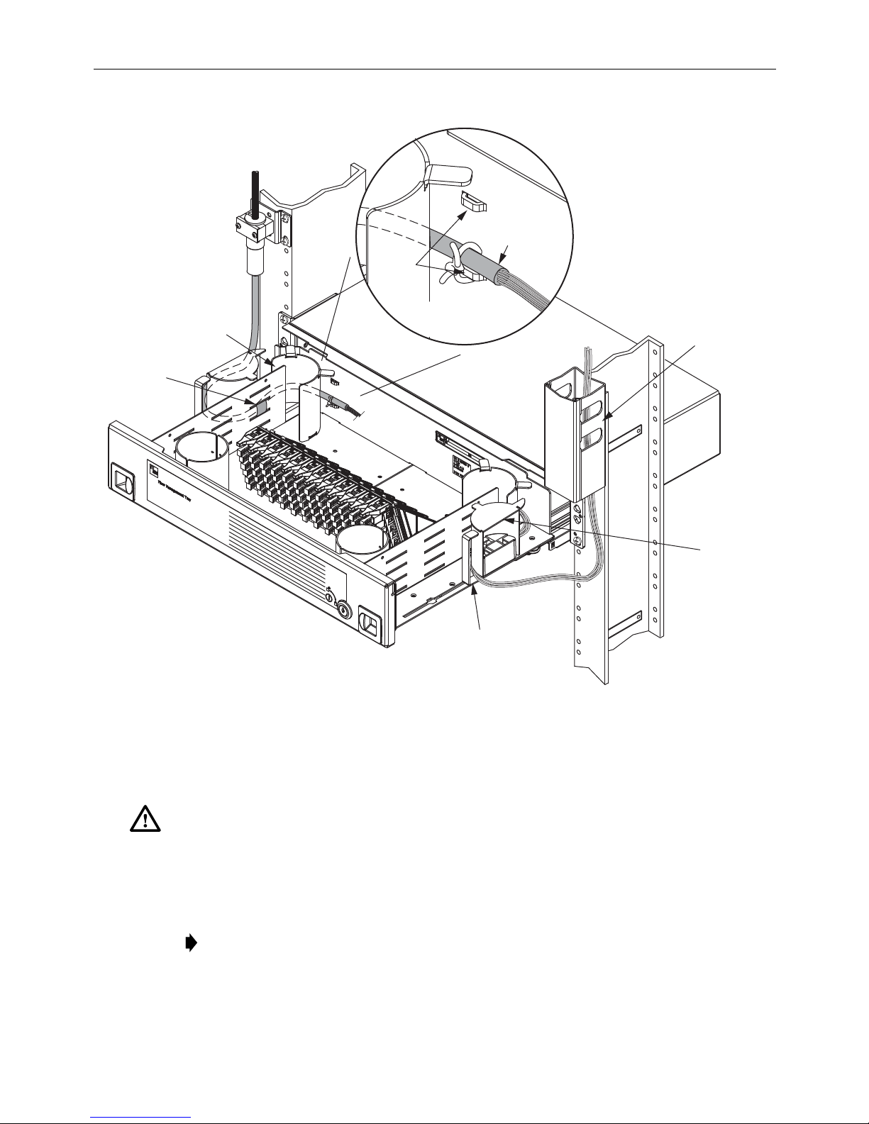
1. Open tray fully and lock it using the lock open latch (see Subsection 7.1 Opening the Tray).
2. Route the cable along the rack to the 2RU FMT, as shown in Figure 13.
Note: The cable may be routed from either above or below the tray. It may be routed into
the 2RU FMT from either the left or right side.
3. Secure the cable to the rack using local practice.
4. Route the cable into the fully-open tray through the cable guide as shown.
Note: The sliding radius limiters must be in the position shown.
Note: Before tying off the cable as shown, proceed with the next step below.
Page 15
© 2016 CommScope. All Rights Reserved.
Page 16
ADCP-90-459 • Issue 2 • June 2016
ROUTE CABLE INTO
2RU THROUGH SLIDING
RADIUS LIMITER
18548-E
REQUIRED
POSITION
OF SLIDING
RADIUS
LIMITER
(2 PLACES)
TIE
LANCES
DETAIL OF
CABLE TIE-OFF
POINTS
VELCRO
TIE-OFF
POINT
ROUTE BEHIND
RADIUS LIMITER
900 MICRON
SUBUNIT
FANOUT
POINT
2 x 2
FiberGuide
Figure 13. Securing Cables Within 72-Position Termination Tray
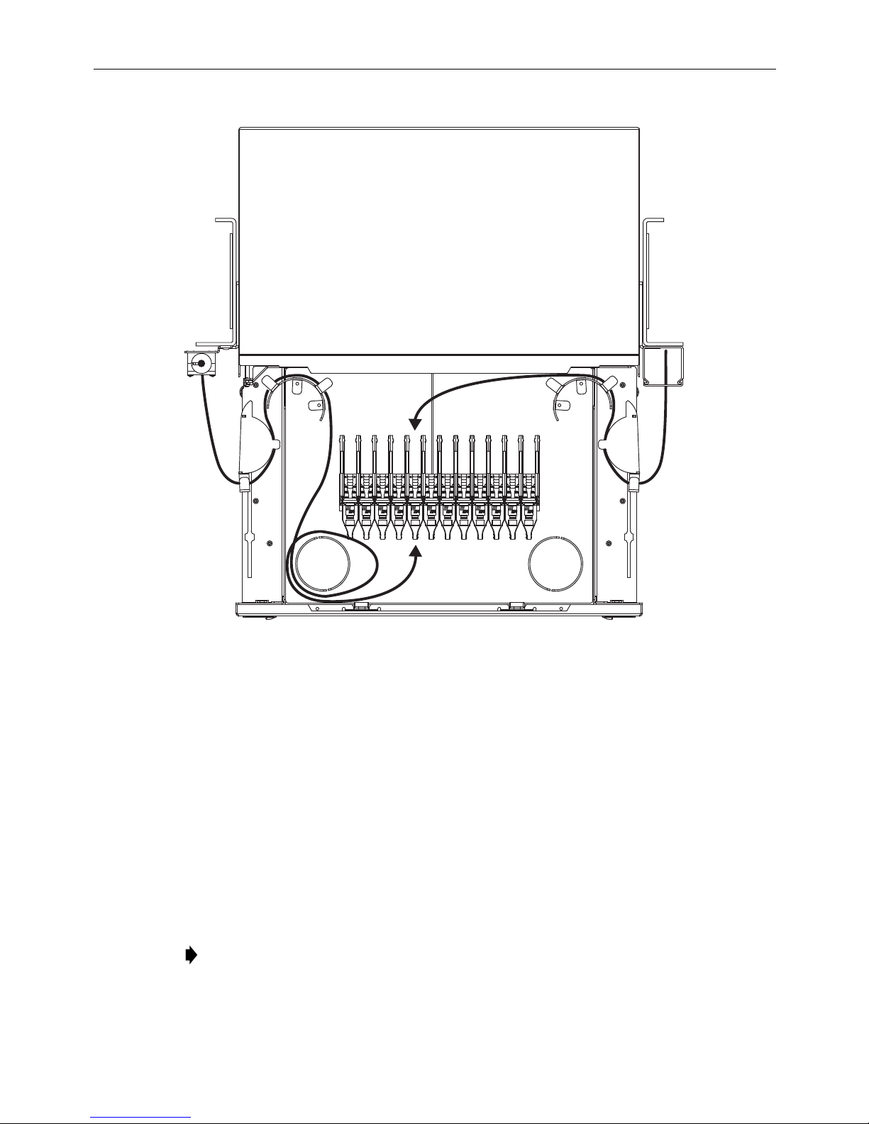
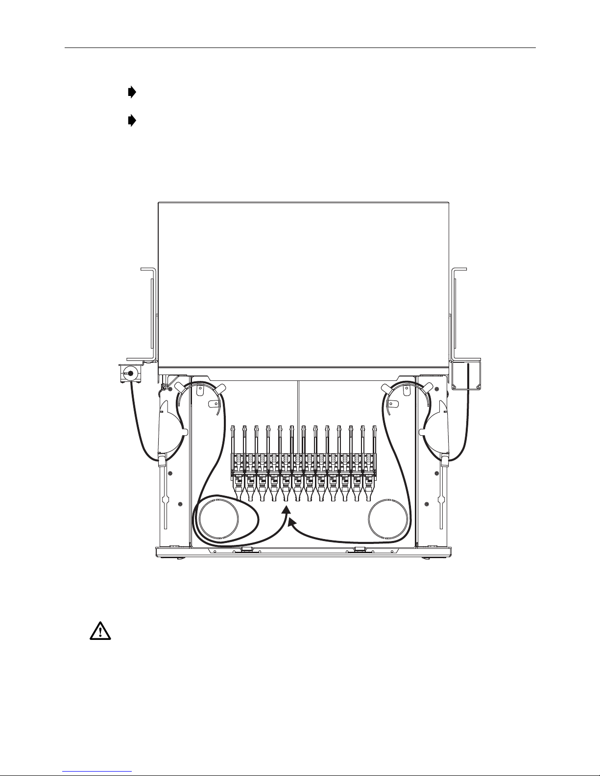
5. Route the cable within the tray as shown in Figure 14. Note that there are different
routings for cables being terminated at the front and rear of the adapters packs.
Danger:
Infrared radiation is invisible and can seriously damage the retina of the eye. Do not
look into the ends of any optical fiber. Do not look directly into the optic al adapters of the adapter
packs. Exposure to invisible laser radiation may result. An optical power meter should be used to
verify active fibers. A protective cap or hood MUST be immediately placed over any radiating
adapter or optical fiber connector to avoid the potential of dangerous amounts of radiation
exposure. This practice also prevents dirt particles from entering the adapter or connector
.
Note: Always clean and inspect connectors and adapters before mating them. For
guidelines, refer to the connector cleaning instructions, ADCP-90-159.
6. Secure the cables on the side and rear of the tray as shown in Figure 13.
Page 16
© 2016 CommScope. All Rights Reserved.
Page 17
ADCP-90-459 • Issue 2 • June 2016
18550-C
Figure 14. Cable Routing for 72-Position Termination Tray
(Use Either This or Mirror Image)
7. To connect an individual cable connector to an adapter, lift up the release tab on top of the
adapter pack and slide up the adapter pack (see Figure 25 on page 2 8). Pull the dust cap
straight out from the adapter and connect the cable connector to the adapter.
6.2.2 Termination (Left Entry for IFC)
Cables routed into the tray for termination are normally pre-terminated individual cables
(simplex or duplex patch cords). Refer to the following instructions.
1. Open tray fully and lock it using the lock open latch (see Subsection 7.1 Opening the Tray).
2. Route the cable along the rack to the 2RU FMT, as shown in Figure 11 on page 14.
Note: The cable may be routed from either above or below the tray on the left side.
3. Secure the cable to the rack using local practice.
© 2016 CommScope. All Rights Reserved.
Page 17
Page 18
ADCP-90-459 • Issue 2 • June 2016
19994-C
LOOP FIBERS ONE
TIME AROUND
SPOOL AS SHOWN
SECURE
SUBUNIT TO
BRACKET
LIGHTLY SECURE
FIBER TO DRAWER
WITH VELCRO
USING SLOTS
IN DRAWER
RIBBON
CABLE
FANOUT
POINT
ADAPTER POSITION
67 THROUGH 72
(67 ON TOP, 72 ON BOTTOM)
ADAPTER POSITION
1 THROUGH 6
(1 ON TOP, 6 ON BOTTOM)
WAX LACING TIE POINT
FOR 900 MICRON SUBUNIT
4. Route the cable into the fully-open tray through the cable guide as shown.
Note: Before tying off the cable as shown, proceed with the next step below.
Figure 15. Cable Routing for 72-Position Termination Tray
(Left Entry Only)
5. Route the cable within the tray as shown in Figure 15. Note that there are different
routings for cables being terminated at the front and rear of the adapters packs.
Danger:
Infrared radiation is invisible and can seriously damage the retina of the eye. Do not
look into the ends of any optical fiber. Do not look directly into the optic al adapters of the adapter
packs. Exposure to invisible laser radiation may result. An optical power meter should be used to
verify active fibers. A protective cap or hood MUST be immediately placed over any radiating
adapter or optical fiber connector to avoid the potential of dangerous amounts of radiation
exposure. This practice also prevents dirt particles from entering the adapter or connector
.
Note: Always clean and inspect connectors and adapters before mating them. For
guidelines, refer to the connector cleaning instructions, ADCP-90-159.
6. Secure the cables on the side and rear of the tray as shown in Figure 15.
Page 18
© 2016 CommScope. All Rights Reserved.
Page 19
ADCP-90-459 • Issue 2 • June 2016
18549-E
REQUIRED
POSITION
OF SLIDING
RADIUS
LIMITER
(2 PLACES)
VELCRO
TIE-OFF
POINT
ROUTE BEHIND
RADIUS LIMITER
ROUTE CABLE INTO
2RU THROUGH SLIDING
RADIUS LIMITER
TIE
LANCES
DETAIL OF
CABLE TIE-OFF
POINTS
900 MICRON
SUBUNIT
FANOUT
POINT
2 x 2
FiberGuide
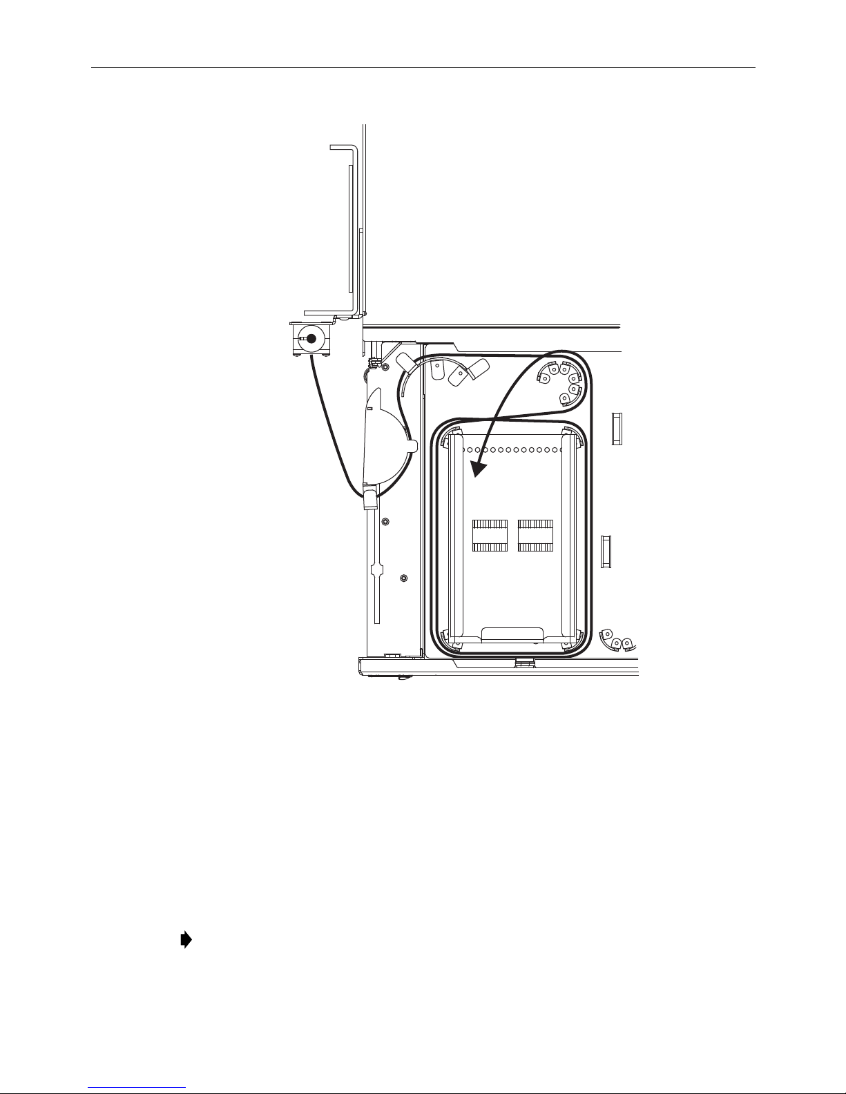
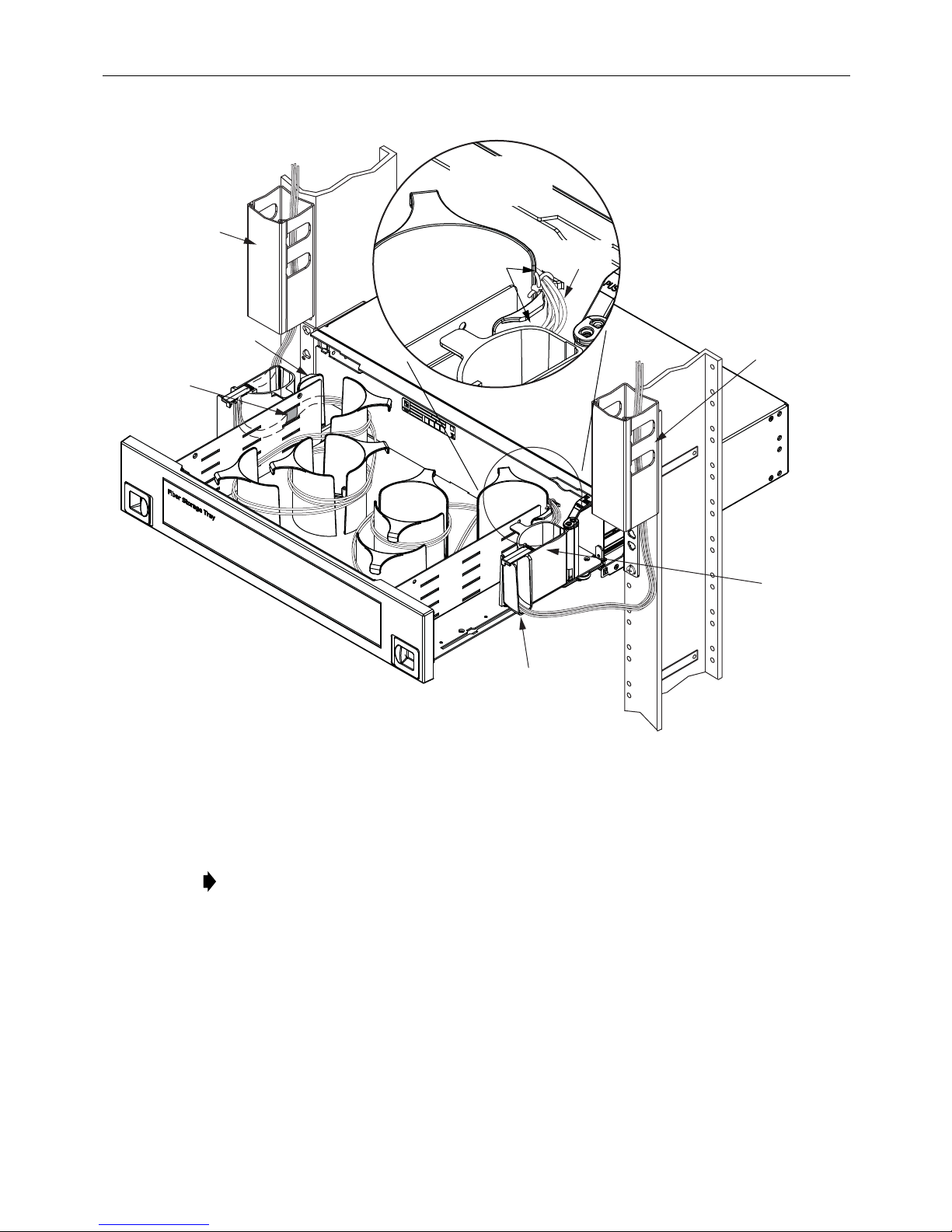
6.2.3 Micro-VAM
Cables routed into the micro-VAM tray are normally pre-terminated individual cables. Refer to
the following instructions.
1. Open the tray fully and lock it using the lock open latch (see
Tray
).
Subsection 7.1 Opening the
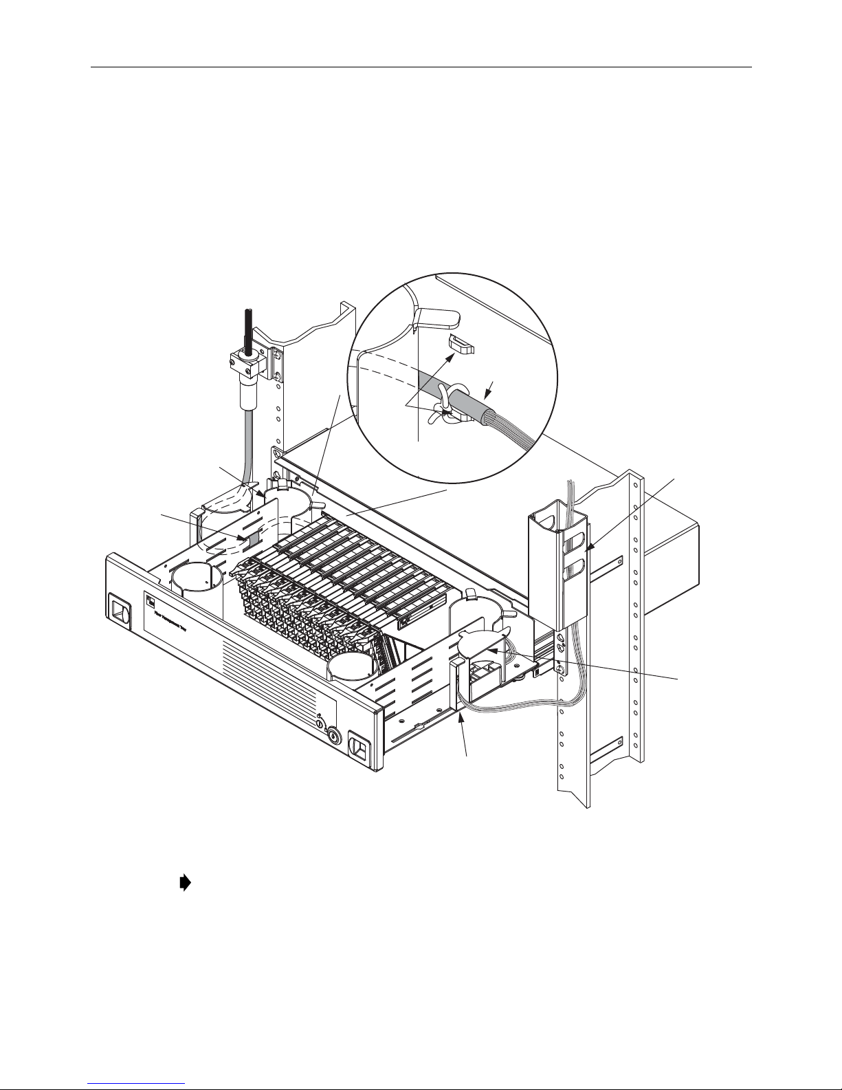
2. Route the cable along the rack to the tray as shown in Figure 16 on page 19.
Figure 16. Securing Cables Within 72-Position Micro-VAM Tray
Note: The cable may be routed from either above or below the tray. The cable may be
routed into the tray from either the left or right side or from both sides
3. Secure the cable to the rack using local practice.
4. Route the cable into the fully-open tray through the cable guide as shown.
© 2016 CommScope. All Rights Reserved.
Page 19
Page 20
ADCP-90-459 • Issue 2 • June 2016
18550-C
Note: The sliding radius limiters must be in the position shown.
Note: Before tying off the cable as shown, proceed with the next step below.
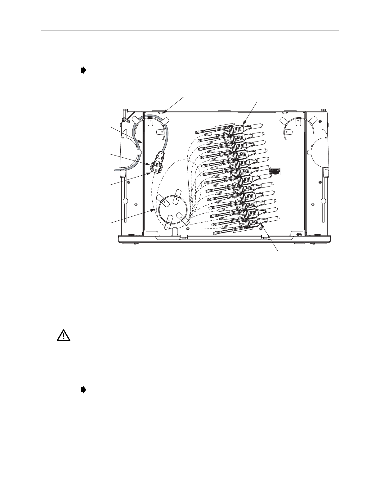
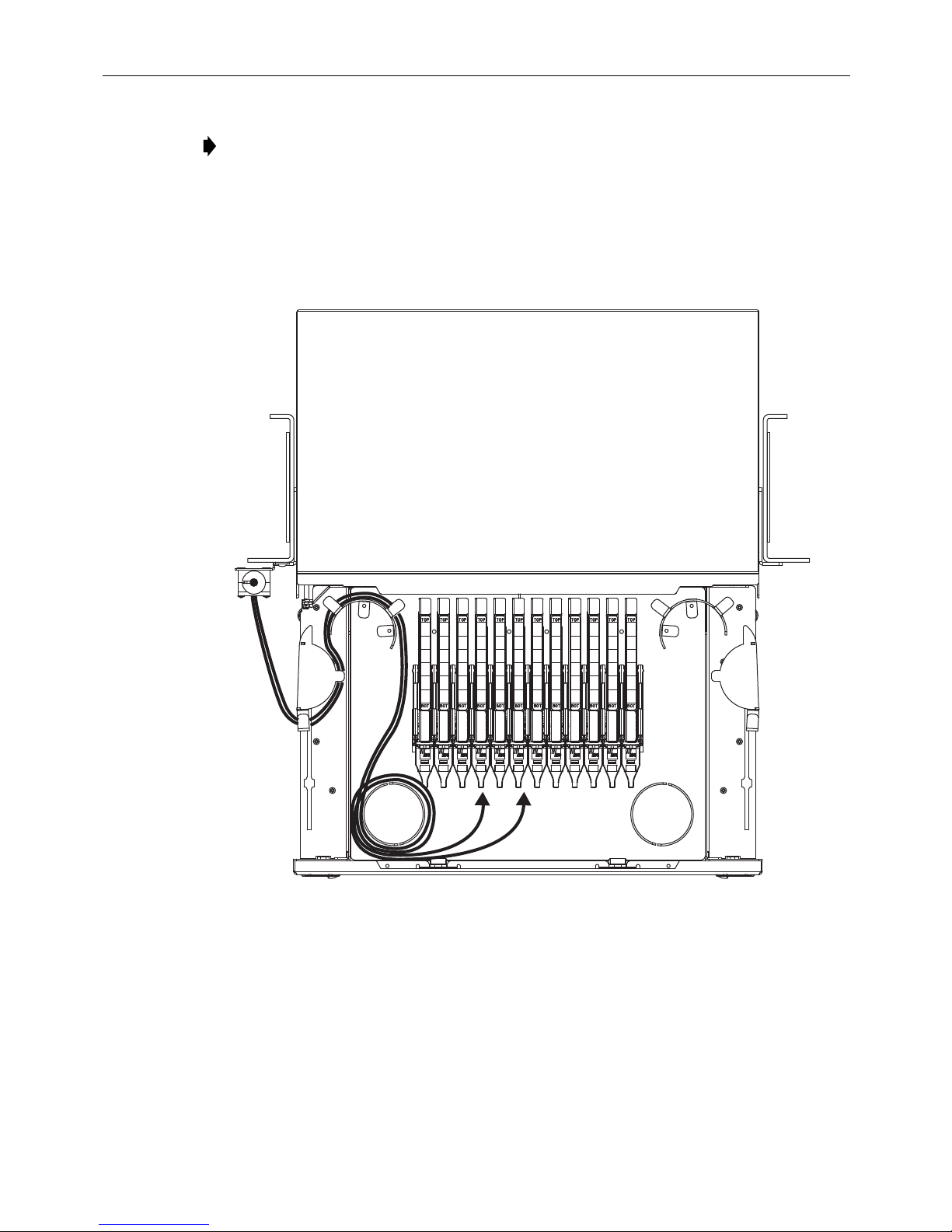
5. Route the cables within the tray as shown in Figure 17 for entry from both sides or as
shown in Figure 18 for entry from either left or right side. (Left side entry is shown.
Routing for right side entry is a mirror image of the routing shown.) All cable are
terminated on the front of the micro-VAMs.
Figure 17. Cable Routing for 72-Position Micro-VAM Tray (Enter From Both Sides)
Danger:
Infrared radiation is invisible and can seriously damage the retina of the eye. Do not
look into the ends of any optical fiber. Do not look directly into the optic al adapters of the adapter
packs. Exposure to invisible laser radiation may result. An optical power meter should be used to
verify active fibers. A protective cap or hood MUST be immediately placed over any radiating
adapter or optical fiber connector to avoid the potential of dangerous amounts of radiation
exposure. This practice also prevents dirt particles from entering the adapter or connector
Page 20
© 2016 CommScope. All Rights Reserved.
.
Page 21
ADCP-90-459 • Issue 2 • June 2016
18649-B
LEFT OR RIGHT
Note: Always clean and inspect connectors and adapters before mating them. For
guidelines, refer to ADCP-90-159.
6. To connect an individual cable connector to a micro-VAM, lift up the release tab on top of
the micro-VAM and slide the micro-VAM upward (see Figure 26 on page 28). Pull the
micro-VAM dust cap straight out and connect the connector to the micro-VAM port.
7. Secure the cables on the side and rear of the tray as shown in Figure 16 on page 19.
6.2.4 48-Position Termination/Splice
Cables routed into the tray for splicing or termination are normally multifiber cable assemblies.
Cables to be spliced will be bare-ended. Cables to be terminated will be pre-terminated. The
2RU FMT will also have factory-installed, internal pigtails between splice tray and connector
bulkhead. Refer to the following instructions.
Figure 18. Cable Routing for 72-Position Micro-VAM Tray
Left or Right Entry (Use Either This or Mirror Image)
Page 21
© 2016 CommScope. All Rights Reserved.
Page 22
ADCP-90-459 • Issue 2 • June 2016
ROUTE CABLE INTO
2RU FMT THROUGH
SLIDING RADIUS LIMITER
19393-C
REQUIRED
POSITION
OF SLIDING
RADIUS
LIMITER
(2 PLACES)
TIE
LANCES
DETAIL OF
CABLE TIE-OFF
POINTS
VELCRO
TIE-OFF
POINT
ROUTE BEHIND
RADIUS LIMITER
900 MICRON
SUBUNIT
FANOUT
POINT
2 x 2
FiberGuide
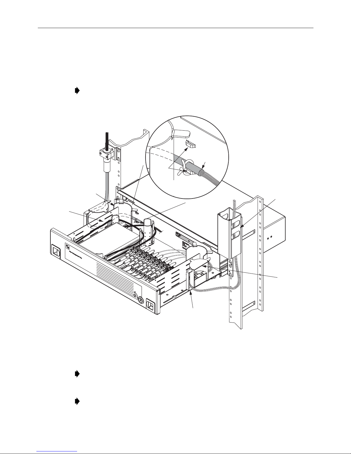
1. Open the tray fully and lock it using the lock open latch (see
Tray
).
2. Route cables along the rack to the 2RU FMT, as shown in
Subsection 7.1 Opening the
Figure 19
. Route cable to be
spliced on the left side of the rack . Rout e cable to be term inated on the righ t side o f the rack .
Note: The cables may be routed from either above or below the tray.
3. Secure the cables to the rack using local practice.
Figure 19. Securing Cables Within 48-Position Termination/Splice Tray
4. Route the cables into the fully-open tray through the cable guides as shown.
Note: The sliding radius limiters must be in the position shown.
5. Route the cables within the tray as shown in Figure 20.
Note: Always clean and inspect connectors and adapters before mating them. For
guidelines, refer to the connector cleaning instructions, ADCP-90-159.
Page 22
© 2016 CommScope. All Rights Reserved.
Page 23
ADCP-90-459 • Issue 2 • June 2016
19394-C
PATCH CORDS
TO TERMINATION
POINT
IFC/OSP
CABLE TO
SPLICE TRAY
PIGTAILS FROM
BULKHEAD TO
SPLICE TRAY
Danger:
Infrared radiation is invisible and can seriously damage the retina of the eye. Do not
look into the ends of any optical fiber. Do not look directly into the optic al adapters of the adapter
packs. Exposure to invisible laser radiation may result. An optical power meter should be used to
verify active fibers. A protective cap or hood MUST be immediately placed over any radiating
adapter or optical fiber connector to avoid the potential of dangerous amounts of radiation
exposure. This practice also prevents dirt particles from entering the adapter or connector
.
Figure 20. Cable Routing for 48-Position Terminatio n/Splice Tray
6. Route the cables within the splice tray as shown in Figure 21.
7. Secure the cables on the side and rear of the tray as shown in Figure 19 on page 22.
8. To connect an individual cable connector to an adapter, lift up the release tab on top of the
adapter pack and slide up the adapter pack (see Figure 25 on page 28). Pull the dust cap
straight out from the adapter and connect the cable connector to the adapter.
Page 23
© 2016 CommScope. All Rights Reserved.
Page 24
ADCP-90-459 • Issue 2 • June 2016
19597-A
6.2.5 Bulk Storage
Cable routed into the tray are typically 1.66mm patch cords. To store the patch cords in a bulk
storage tray, refer to the following instructions.
1. Open the tray fully and lock it using the lock open latch (see
Tray
).
2. Route the patch cords along the rack to the 2RU FMT, as shown in
patch cords in from either side o f the tray.
Note: The cables may be routed from either above or below the tray.
Page 24
© 2016 CommScope. All Rights Reserved.
Figure 21. Routing Within Splice Tray
Subsection 7.1 Opening the
Figure 22
. Route the
Page 25
2 x 2
FiberGuide
DETAIL OF
CABLE TIE-OFF
POINTS
TIE
LANCE
LOCATIONS
ADCP-90-459 • Issue 2 • June 2016
2 MM
CABLES
ROUTE BEHIND
RADIUS LIMITER
VELCRO
TIE-OFF
POINT
ROUTE CABLE INTO
2RU FMT THROUGH
SLIDING RADIUS LIMITER
Figure 22. Routing Patch Cords into Bulkhead Storage Tray
2 x 2
FiberGuide
REQUIRED
POSITION
OF SLIDING
RADIUS
LIMITER
(2 PLACES)
24297-A
3. Secure the patch cords to the rack using local practice.
4. Route the patch cords into the fully-open tray through the cable guides as shown.
Note: The sliding radius limiters must be in the position shown.
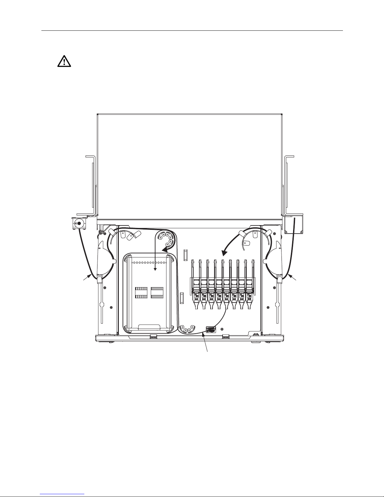
5. Route the patch cords within the tray as shown in Figure 23.
© 2016 CommScope. All Rights Reserved.
Page 25
Page 26

ADCP-90-459 • Issue 2 • June 2016
24299-A
Figure 23. Cable Routing for Bulk Storage FMT Panel
6. Route the patch cords within the tray as shown in Figure 23.
Note: For maximum storage, balance the load between the two sides.
7 OPERATION
Operation consists of opening the tray, connecting patch cords to adapters or micro-VAMs, and
closing the tray. When routing patch cords, refer to the routing diagrams provided in Section 6.
Page 26
© 2016 CommScope. All Rights Reserved.
Page 27

ADCP-90-459 • Issue 2 • June 2016
24301-A
LOCK
OPEN
LATCH
PUSH DOWN
TO RELEASE
LOCK
Danger:
Infrared radiation is invisible and can seriously damage the retina of the eye. Do not
look into the ends of any optical fiber. Do not look directly into the optic al adapters of the adapter
packs. Exposure to invisible laser radiation may result. An optical power meter should be used to
verify active fibers. A protective cap or hood MUST be immediately placed over any radiating
adapter or optical fiber connector to avoid the potential of dangerous amounts of radiation
exposure. This practice also prevents dirt particles from entering the adapter or connector
7.1 Opening the Tray
To open the 2RU FMT tray, slide the release tabs inward with both hands and pull the drawer
straight out as far as it goes. While working in the tray, lock tray in position as shown in
Figure 24. Press latch down to unlock tray and push closed.
Caution: Placing a load in excess of 12 pounds (5.4 kg) onto an open tray will result in
misalignment or damage to the tray.
.
7.2 Sliding Adapter Packs
To access a sliding adapter pack (Figure 25):
1. Route the patch cord into the tray as shown in the appropriate diagram in Section 6.
Figure 24. Tray Locked in Open Position
© 2016 CommScope. All Rights Reserved.
Page 27
Page 28

ADCP-90-459 • Issue 2 • June 2016
18650-A
2. Lift up the release tab and slide up the adapter pack.
Note: Always clean and inspect connectors and adapters before mating them. For
guidelines, refer to ADCP-90-159.
3. Pull the dust cap straight out.
4. Connect the patch cord connector to the adapter and slide the adapter pack back down.
5. Close the tray as described in Subsection 7.4 Closing the Tray.
Figure 25. Removing Dust Cap From Standoff Style Adapter Pack
7.3 Micro-VAMs
To access a micro-VAM (Figure 26):
1. Route the patch cord into the tray as shown in the appropriate diagram in Section 6.
2. Lift up the release tab and slide up the micro-VAM.
Note: Always clean and inspect connectors and adapters before mating them. For
guidelines, refer to ADCP-90-159.
3. Pull the dust cap straight out.
4. Connect the patch cord connector to the desired adaptor.
5. Close the tray as described in Subsection 7.4 Closing the Tray.
Page 28
© 2016 CommScope. All Rights Reserved.
Page 29

ADCP-90-459 • Issue 2 • June 2016
18651-A
7.4 Closing the Tray
Close the tray using the following procedure:
1. Fully lower and seat all connector or micro-VAM 6-packs.
2. Assure that all cables and fibers are properly secured and located below the top surface of
the tray.
3. Release the lock open latch (“unlocked position” shown in Figure 24 on page 27).
4. Slowly close the tray, observing that no fiber kinks or macro bends occ ur as a result of
fiber routing.
5. Latch tray shut using the lock open latch (“locked position” shown in
Figure 26. Accessing a Micro-VAM
Figure 24 on page 27
).
© 2016 CommScope. All Rights Reserved.
Page 29
Page 30

ADCP-90-459 • Issue 2 • June 2016
8 TECHNICAL ASSISTANCE
Contact the Technical Assistance Center (TAC) for technical question. Call 800.830.5056 or
send an email to TAC.Americas@commscope.com.
Page 30
© 2016 CommScope. All Rights Reserved.
 Loading...