

Page 1

• Thank you for purchasing COMMAX products.
• Please carefully read this User’s Guide (in particular, precautions for safety) before using a product and follow
instructions to use a product exactly.
• The company is not responsible for any safety accidents caused by abnormal operation of the product.
COMMAX CONVERTER UNIT CCU-232AGF
User Manual
Page 2

1
Table of Contents
1. Feature ..............................................................................................................1
2. Warnings and caution.........................................................................................2
3. The name & Function ........................................................................................4
4. Manual to use.....................................................................................................5
5. System Diagram.................................................................................................9
6. wiring ................................................................................................................10
7. Precautions. .....................................................................................................11
8. Others...............................................................................................................11
9. Specifications and Characteristics ...................................................................11
1. Feature
●
This unit as a 32-channel distributor has to be use a power adapter separately.
●
If a CCU-232AGF is installed among CCU-204AGFs, It has to be used by
connecting 8-wires among floor distributors for power supply among CCU204AGFs.
●
This unit can be used by connecting with the 2-wire loop type Interphone
(ex. AP-2SAG) manufactured in COMMAX.
●
This unit can be also used by connecting with Phone what has a keypad.
●
This unit connect with a lobby phone in 6-wires.
●
Remote updating is possible by guard phone.
●
Please make sure to check the wire sequence.
●
Avoid duplication other devices ID.
●
This unit s using a Power of DC24V/3A(Recommended RF-24AS by COMMAX).
Page 3
2
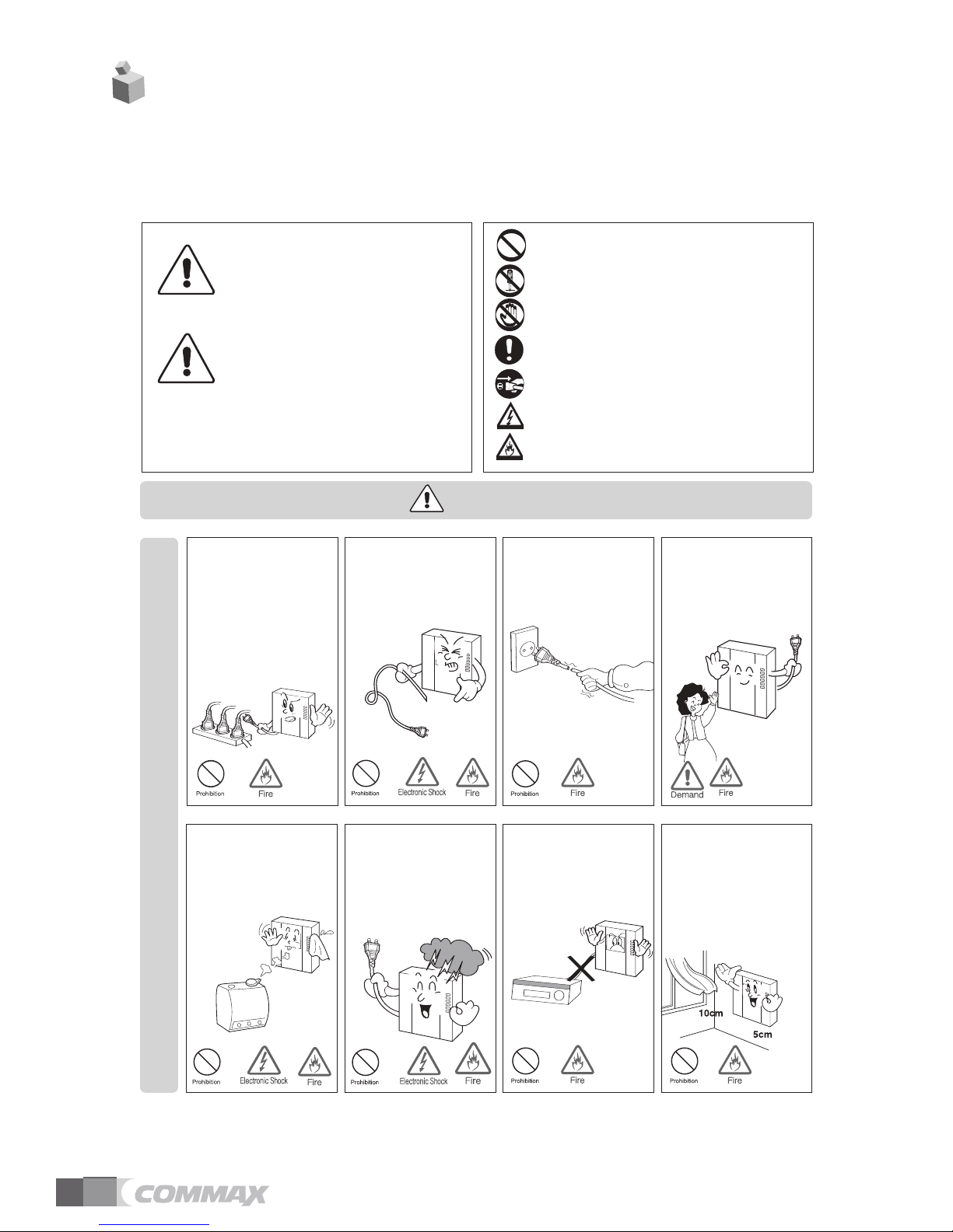
Please follow the things described below in order to prevent any
danger or property damage.
Warning
Caution
Prohibition.
N
o disassembly
No touch
Must follow strictly.
S
hows plugging out the power cord
without an exception
Shows the warning and caution for an electric shock.
Shows the warning and caution for a fire.
I
t may cause a minor damage or injury if violated.
I
t may cause a serious damage or injury if
v
iolated.
Power & Installation
Warning
Please don’t use several
products at the same time on
one power socket.
·
It may cause a fire due to an
abnormal overheating.
Please don’
t bend the power
cable excessively or it may
cause an electric shock.
·
fire when using a damaged
power cable.
Please don’
t handle the power
cable with a wet hand.
·
It may cause an electric
shock.
Please plug out the power
cable from the socket when
not using it for a long period
of time.
·
It may shorten the product
lifespan or cause a fire.
Please don’
t install the
product in the place where
there is much oil, smoke or
humidity.
·
It may cause an electric
shock or fire.
Please don’t install the
product with the lightening
and thunder.
·
It may cause an electric
shock or fire.
Please don’
t use and connect
this product with other
products with different rated
voltage
·
It may cause a disorder or
fire.
When installing the product
that generates heat, please
install the product away from
the wall (10cm) for the
ventilation.
·
It may cause a fire due to
the increased internal
temperature.
2. Warnings and caution
Page 4

3
Cleaning & Use
Please don’t disassemble,
repair or rebuild this product
arbitrarily (please contact the
service center if a repair is
n
eeded.
·
I
t may cause an electric
s
hock or fire.
Please plug the power cable
firmly into the inner end
·
It may cause a fire.
Please hold the plug tightly
when unplugging the power
cable (a part of the copper
wire may be disconnected if
the grabbing is only made on
the cord when pulling out the
cable).
·
It may cause an electric
shock or fire
When connecting the power
cables after cutting the cable,
please install the product with
power off
·
It may cause an electric
shock or fire
When installing the product,
please fix it firmly while using
the wall-mounting unit and
screws.
·
It may cause an injury from
the falling object.
Please be careful when using
an AC circuit breaker since
there is a possibility of an
electric shock.
When cleaning the product,
please rub it with a soft and
dry cloth after plugging out
the power cable. (Please don’
t
use any chemical products
such as wax, benzene, alcohol
or cleanser.)
Please don’
t drop the product
on the ground and don’
t apply
a shock .
·
It may cause a failure.
Please use the designated
connection cable within the
maximum calling distance
designated for the product
·
It may reduce the product
performance.
Please check the use voltage
and current for the DC-only
products and use the
appropriate rectifier.
·
It may cause a fire.
Please avoid direct rays of the
sun or heating devices at a
time of installation.
·
It may cause a fire.
Please don’
t install the
product on an unstable place
or small support board.
·
It may cause an injury if it
falls down while in use.
If an abnormal sound, burning
smell or smoke is coming out
of the product, please plug out
the power cable and contact a
s
ervice center.
·
I
t may cause an electric
s
hock or fire.
P
lease don’
t
insert any
m
etallic or burnable materials
into the ventilation hole.
·
It may cause an electric
shock or fire.
P
lease use only the designated
b
atteries for the products of
u
sing DC power.
·
It may cause an electric
shock or fire.
Cleaning & UsePower & Installation
Warning
Caution
Page 5

4
No.
1
2
3
4
5
No.
6
7
8
9
PartPart
Household input & output
Common line input
Common line input
Program terminal
Connect terminal
Power Input Terminal
STATUS LED
ID SWITCH
POWER SWITCH
3. The name & Function
3-1. Draft & Table Name
3-2. FUNCTION
①
Household in& output terminal : house hold call line input terminal.
②
Common line output terminal : Distributor Common line output terminal
③
Common line input terminal :
Lobby Common line & Distributor common line input terminal
④
Program terminal : This product is a terminal for program download.
⑤
RS-232 Connection terminal : you can use it If you change settings by a PC.
⑥
Power input terminal : RF-24AS Adaptor connection terminal.
⑦
Status LED : LED is on depending to the status.
1) Power LED : The LED is on when the power is on.
2) Lobby call LED : The LED is on when calling between HOUSEHOLD & LOBBY.
3) Guard call LED : The LED is on when calling between Household & Guard or House
hold.
4) Data LED : The LED is on when transferring data between devices.
5) Error check LED : The LED is on when Error.
⑧
The Switch to set up the ID : This is The DIP SWITCH to set the ID.
⑨
Power switch : ON/OFF SWITCH FOR POWER.
Page 6

5
4-1. Door open function of the Lobby (Control function of household interphone)
- Pls. proceed as follows if you want to open the door with the interphone while talking to
Lobby phone.
4-1-1 : Method using the Hook switch
(1) Press & release the hook switch for 1 seconds.
(2) This opens the door.
(3) Pls. down the handset To end the call.
(Caution : Guard room is called if you do not hang up in a period time)
4-1-2 : The way to use the button for opening a door.
(if you have a door open button in a household.)
(1) Press the door open button while talking to the lobby.
(2) Door is opened.
(3) Pls. down the handset To end the call.
4-2. The function of DTMF
- Pls. proceed as follows if you want to call the guard(or ohter household unit) or open
the door.
4-2-1 The way to call other household unit
(1) Press the building number using keypad.
(2) Press '*' the building button.
(3) Press the unit number using keypad.
(4) Press '#' the call button.
(5) Talk as answered.
4-2-2 The way to call the guard station.
(1) Press the '#' the call button while hooking off.
(2) Talk as answered.
4-2-3 The way to open the door.
(1) Press the door open button while talking to the lobby.
(2) Door is opened.
(3) Pls. down the handset To end the call.
4. Manual to use
Page 7

6
4-3. When changed by the guard phone :
refer to the use manual of linkage guard phone
4-4 The Method to set the device ID
You should set the device ID up BCD code using DIP switch.
1) DIP switch is divided into two parts, Lower 4 bits(1~4) and Upper 4 bits(5~8)
2) Lower bits are set up unit's place and Upper are ten's place.
- You can set up to 99 IDs maximally.
Page 8

7
5. System Diagram
Page 9

8
6. wiring
Page 10

9
Model
CCU-232AGF
Wiring To Lobby 6 Common Wires, To Floor Distributer 8 Common Wires
Power 24V / 3A
Standby : 100mA
Maximum : 330mA
200 meter / ر0.65mm wire
Household ↔
CCU-232AGF ↔ Guard
Power
consumption
Range
●
The product is damaged or if an error occurs, please contact directly to customer support
team in headoffice.
●
Do not place a flower vase or bottle on the product.
●
A proper cutoff( the device can cut all) must be used Indoor wiring in a building when risk
of fire or equipment occurs, press down the breaker of the building as soon as possible.
●
First of all, off the power & install the unit or repair the product.
7. Precautions.
●
Before making a call for a faulty equipment, please read the manual thoroughly.
●
Please check all status prior to making a customer service call.
8. Others
9. Specifications and Characteristics
Page 11

513-11, Sangdaewon-dong, Jungwon-gu, Seongnam-si, Gyeonggi-do, Korea
Int’l Business Dept. Tel. : +82-31-7393-540~550 Fax. : +82-31-745-2133
Web site : www.commax.com
Printed In Korea / 2014.01.104
PM32232AGF10
 Loading...