

Page 1

• Thank you for purchasing COMMAX products.
• Please carefully read this User’s Guide (in particular, precautions for safety) before using a product and follow
instructions to use a product exactly.
• The company is not responsible for any safety accidents caused by abnormal operation of the product.
Video - Door Phone CAV-40NG
User Manual
Page 2

● Thank you very much for choosing COMMAX.
● Please read this manual carefully before you use the product.
Table of contents ......................................................................................................1
1. Greetings...............................................................................................................1
2. Warnings and caution...........................................................................................2
3. Part names and functions .....................................................................................4
4. Operating..............................................................................................................5
5. Installation ........................................................................................................11
6. Wiring ...............................................................................................................12
7. Parts list .............................................................................................................13
8. Miscellaneous.....................................................................................................13
9. Specification.......................................................................................................14
Table of contents
1. Greetings
1
Page 3

14
Rating Voltage 100-240V~, 50/60Hz (FREE VOLTAGE)
Consumption Maximum : 10W, On stand-by : 5W
To a Camera unit 4 wires polarity,
To Lobby Panel 8 wires polarity
Monitor 4" COLOR TFT-LCD, Digital LCD
Communication Full duplex(Handset)
From door and lobby : Electronic chime 2 times (Sol- mi-do)
From Security(Guard) : Electronic melody
Monitoring : 30 seconds
Monitor Display Upon talking : 60 seconds
Guard station : 3 minutes.
From Door : 50m(Ø0.65mm)
Working distance From Lobby Panel : 300m
From Guard : 1Km
Temperature 0 ~ +40℃(32℉~ 104℉)
Dimension 249(W)X158.5(H)X47.6(D) (Based on Max height of handset)
CAV-40NG
Model
Spec
9. Specifications
Wiring Method
Call tone
Page 4

2. Warnings and caution
2
Please follow the things described below in order to prevent any
danger or property damage.
Warning
Caution
Prohibition.
No disassembly
No touch
Must follow strictly.
Shows plugging out the power cord
without an exception
Shows the warning and caution for an electric shock.
Shows the warning and caution for a fire.
It may cause a serious damage or
injury if violated.
It may cause a minor damage or
injury if violated.
Power & Installation
Warning
Please don’t use several
products at the same time on
one power socket.
·It may cause a fire due to an
a
bnormal overheating.
Please don’t bend the power
cable excessively or it may
cause an electric shock.
·fire when using a damaged
power cable.
Please don’t handle the power
cable with a wet hand.
·It may cause an electric
shock.
Please plug out the power
cable from the socket when
not using it for a long period
of time.
·It may shorten the product
lifespan or cause a fire.
Please don’t install the
product in the place where
there is much oil, smoke or
humidity.
·It may cause an electric
shock or fire.
Please don’t install the
product with the lightening
and thunder.
·It may cause an electric
shock or fire.
Please don’t use and connect
this product with other
products with different rated
voltage
·It may cause a disorder or
fire.
When installing the product
that generates heat, please
install the product away from
the wall (10cm) for the
ventilation.
·It may cause a fire due to
the increased internal
temperature.
Page 5

3
Cleaning & Use
Please don’t disassemble,
repair or rebuild this product
arbitrarily (please contact the
service center if a repair is
needed.
·It may cause an electric
shock or fire.
Please plug the power cable
firmly into the inner end
·It may cause a fire.
Please hold the plug tightly
when unplugging the power
cable (a part of the copper
wire may be disconnected if
the grabbing is only made on
the cord when pulling out the
cable).
·It may cause an electric
shock or fire
When connecting the power
cables after cutting the cable,
please install the product with
power off
·It may cause an electric
shock or fire
When installing the product,
please fix it firmly while using
the wall-mounting unit and
screws.
·It may cause an injury from
the falling object.
Please be careful when using
an AC circuit breaker since
there is a possibility of an
electric shock.
When cleaning the product,
please rub it with a soft and
dry cloth after plugging out
the power cable. (Please don’t
use any chemical products
such as wax, benzene, alcohol
or cleanser.)
Please don’t drop the product
on the ground and don’t apply
a shock .
·It may cause a failure.
Please use the designated
connection cable within the
maximum calling distance
designated for the product
·It may reduce the product
performance.
Please check the use voltage
and current for the DC-only
products and use the
appropriate rectifier.
·It may cause a fire.
Please avoid direct rays of the
sun or heating devices at a
time of installation.
·It may cause a fire.
Please don’t install the
product on an unstable place
or small support board.
·It may cause an injury if it
falls down while in use.
If an abnormal sound, burning
smell or smoke is coming out
of the product, please plug out
the power cable and contact a
service center.
·It may cause an electric
shock or fire.
Please don’t insert any
metallic or burnable materials
into the ventilation hole.
·It may cause an electric
shock or fire.
Please use only the designated
batteries for the products of
using DC power.
·It may cause an electric
shock or fire.
Cleaning & UsePower & Installation
Warning
Caution
Page 6

4
3. Part names and functions
①
②③
④
⑩
⑤
⑥
⑦⑧
⑨
Name
NO
.
1 Menu & Bright Buton Press to open Menu and Bright.
2 Handset The phone's handset receiver
3 Screen 4" TFT LCD
4 Monitoring button Press this button to check the entrance status
5 Security call button Press this button to call securities
Door strike of connected door camera is open during the
communication with door camera.
7 Power switch ON / OFF switch
8 Volume switch Control incoming volume
Wiring & programming Terminals for wiring with door cameras, interphones and for upgrade
terminals tools.
10 Power indicator LED Light
Details
Door open button
6
9
Page 7

4. Operating
5
The visitor
presses the
call button on
the camera
A chime
sounds
To check
The visitor’s
image appears
on the monitor
Hang-up the
handset
Ends the call
A view of the front door can be seen anytime the
entrance button is pressed and a dialog can be made
with anyone at the front door.
Dialog duration
60 seconds at
a time
Open the door
TThhee ddoooorr rreelleeaassee ffuunnccttiioon
n
ooppeerraatteess oonnllyy wwhheenn tthhee vviissiittoorr’’s
s
iimmaaggee iiss ddiissppllaayyeedd oonn tthhee ssccrreeeen
n
Dialog begins
1-1. Call from the individual entrance
1-2. Call from the common entrance
1-3. Communication between guard station and household
① Paging guard station
✽ Pick up the handset and press Security call button
✽ Emit call sound.
✽ Dialog begins when the security answers.
② Call from guard station
✽ Power light blinks with call sound.
✽Pick up the handset and talk.
✽ hang up the handset when the conversation is finished.
The visitor
presses the
call button on
the camera
A chime
sounds
The visitor’s
image appears
on the monitor
Ends the call
Dialog duration
60 seconds at
a time
Open the door
TThhee ddoooorr rreelleeaassee ffuunnccttiioon
n
ooppeerraatteess oonnllyy wwhheenn tthhee vviissiittoorr’’s
s
iimmaaggee iiss ddiissppllaayyeedd oonn tthhee ssccrreeeen
n
Dialog begins
1. Calling of visitor
Page 8

6
•VIDEO SET(Separately for individual door and common entrance) :Brightness,
Contrast & Color can be adjusted.
•HOME SET : To input house information.
• UTILITY : Calling sound ON/OFF
• INFORMATION : For verifying model name and version.
1.
Press the "Menu” button on communication or monitoring status, to see below setting
display.
2. Press the “MENU” button more than 3 seconds, to see below setting display.
2. SETTING
1-4. Monitoring
① In case both lobby and individual cameras are installed
✽ Click the monitor button once in standby mode to check the images from Individual camera. Click the
button twice for Lobby images and three times for returning to stnadby mode. (Note. it is not available
during the talk)
② In case only lobby camera is installed.
✽ Click monitor button once in standby mode to check the images from lobby and click the button twice to
return to stnadby mode
Page 9

7
1. BRIGHTNESS : Selectable between 0~20 . Default : 10
2. CONTRAST : Selectable between 0~20 . Default : 10
3. COLOR : Selectable between 0~20 . Default : 10
※ How to adjust
1) Move to specific item using ‘move’ button on front side.
2) Press ‘select’ button to enter the adjust screen.
3) Use ‘move’ button to adjust the number.
4) Press ‘select’ button and come back to menu after adjustment.
4. RESET : Reset brightness, contrast & color (re-sets all to default “10”)
Press ‘select’ button, move to “yes” and press ‘ select’ button again.
※ Note : Screen adjustment shall be done separately on Door camera screen / Lobby
panel screen.
5. EXIT : Press ‘select’ button to exit from the menu.
▶
▶
VIDEO SET (To adjust video settings : separately for Door camera and Lobby
panel)
On the menu, enter VIDEO SET, and select to enter DOOR VIDEO SET or LOBBY
VIDEO SET.
•INFORMATION : For verifying model name and version (Common)
•4 buttons on side of the product are used for setting.
Exit menu : “MENU” button – for entering into & exiting from the menu.
Select & input : “SELECT” (Security button on front side) – To select a menu and to
confirm.
Move up /right : “▲” (Monitoring button on front side) - To move to another item.
Move down/left : “▼” (Door open button on front side) – To move to another item.
Page 10

8
1. SOUND MUTE : Select to turn off the sound.
: Calling sound on / : Calling sound off
※ Note : You will not hear calling sound from Door camera and Lobby panel.
2. EXIT : Press ‘select’ button to move back to setting menu.
▶
▶
UTILITY
On setting screen, move to “UTILITY” using ‘move’ button, press ‘select’ button to
enter below screen.
▶
▶
INFORMATION
On the setting screen, move to “INFORMATION” item using ‘move’ button on
front side, then press ‘select’ button to enter.
Page 11

9
▶
▶
HOME SET (For input house information)
Press ‘menu’ button more than 3 seconds on standby mode, to see below setting
screen.
1. HOME No.Set
1) When you move to ‘HOME No.Set’ item, you will see current Home information.
※Note : Initial set numbers are 1234-5678]
2) Press ‘select’ button to see below setting screen.
1) Model : Shows model name. [CAV-40NG]
2) Version : Shows product version.
(Actual product version can be different from above version)
3) Home ID : Shows the building No. and house No. currently set.
(For example, above shows building No. 1234 and house No. 5678)
4) Video : Shows current video method. (PAL / NTSC)
5) Video IN : Shows current source of video signal. (DOOR / LOBBY)
Page 12

10
2) Choose number using ‘ move’ button and input the number using ‘ select’ button.
(When you finish to input 4 digits the password is automatically saved.)
※Note : Initial set number is ‘1234’ ..
CAUTION : For your safety please avoid succeeding numbers or same
numbers.
(0000, 1234 and 4321 are not avilable as password for a security reason.)
3. EXIT : Press ‘select’ button to exit setting.
▶
▶
Changing Password of Lobby Panel. (PASSWORD)
1) Move to “ Password” item and press ‘select’ button to see below setting screen.
▶
▶
RESET
On stand-by status, press ‘Open’ button and ‘ Security Call’ button simultaneously
for more than 3 seconds.
Caution : When you reset the product all information & setting of Video Set
and Home Information come back to default.
(3) Choose number using ‘ move’ button and press ‘ select’ button to input, from
the first digit.
: 8 numbers can be input. For empty space input “0”
(Ex. For building No. 101 and house No. 1 : input 0101 – 0001)
To correct the wrong number select “ ◀ ”
4) When you finish to input all 8 digits, the home information is changed.
Page 13
11
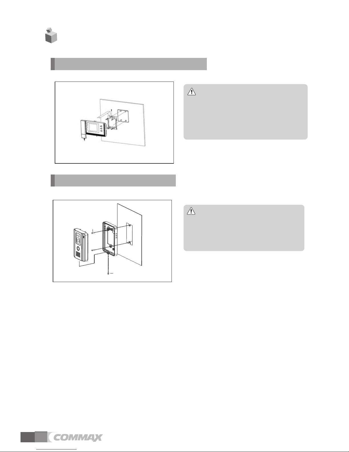
5. Installation
2. Installation Method of camera
Note
① Do not install the camera where
it is exposed to Direct sunlight
② Keep cleaning up its lens to
capture good views.
SCREW T4X18(2EA)
SCREW M3X8(1EA)
DRC-40CK
1. Installation Method of camera monitor
Note
① Avoid the range of direct sunlight
② Recommended height is pertinent
from 1450 ~ 1500mm
③ Avoid the installation near magnetic
activity, humid temperatures and gas
Page 14
12
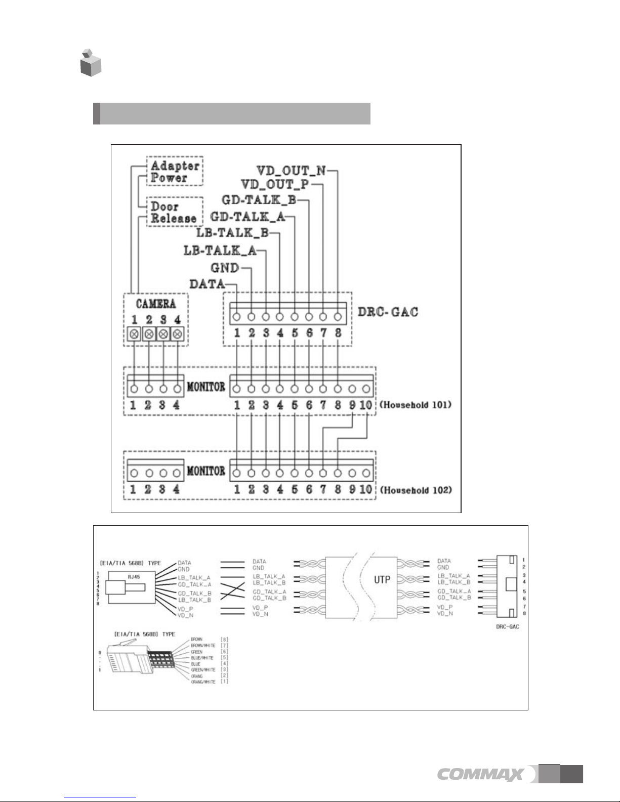
6. Wiring
Connection with DRC-GAC
Page 15

13
7. Parts List
Body of CAV-40NG
Wall mount bracket
User manual
MANUAL
(T)4 X 18mm(4EA)
Screws for mounting
(M3) X 6mm(1EA)
Screws for main body
4P(1EA), 10P(1EA)
Connector
8. Miscellaneous
●
Please carefully read this User's Guide before calling service man
After checking the entire check list, please contact customer service center.
We will do our best to make you satisfy with our services.
Wiring precautions
1. If high voltage cables are present in the vicinity, use a coaxial cable with metal outer
casing.
2. If any internal wires are exposed through mis-wiring, it may cause a short and become
a cause of malfunction or fire.
3. When connecting the monitor and camera, please make sure that the monitor power is
off
4. Please be aware that the wire between camera and monitor has polarity
5. Please be aware that the wire between CAV-40NG and common entrance has polarity
Page 16

513-11, Sangdaewon-dong, Jungwon-gu, Seongnam-si, Gyeonggi-do, Korea
Int’l Business Dept. Tel. : +82-31-7393-540~550 Fax. : +82-31-745-2133
Web site : www.commax.com
Printed In Korea / 2011.11.104
PM0240NG0011
 Loading...