

Page 1
Before installing, operating or adjusting this
product,
please read this instruction booklet
carefully and completely.
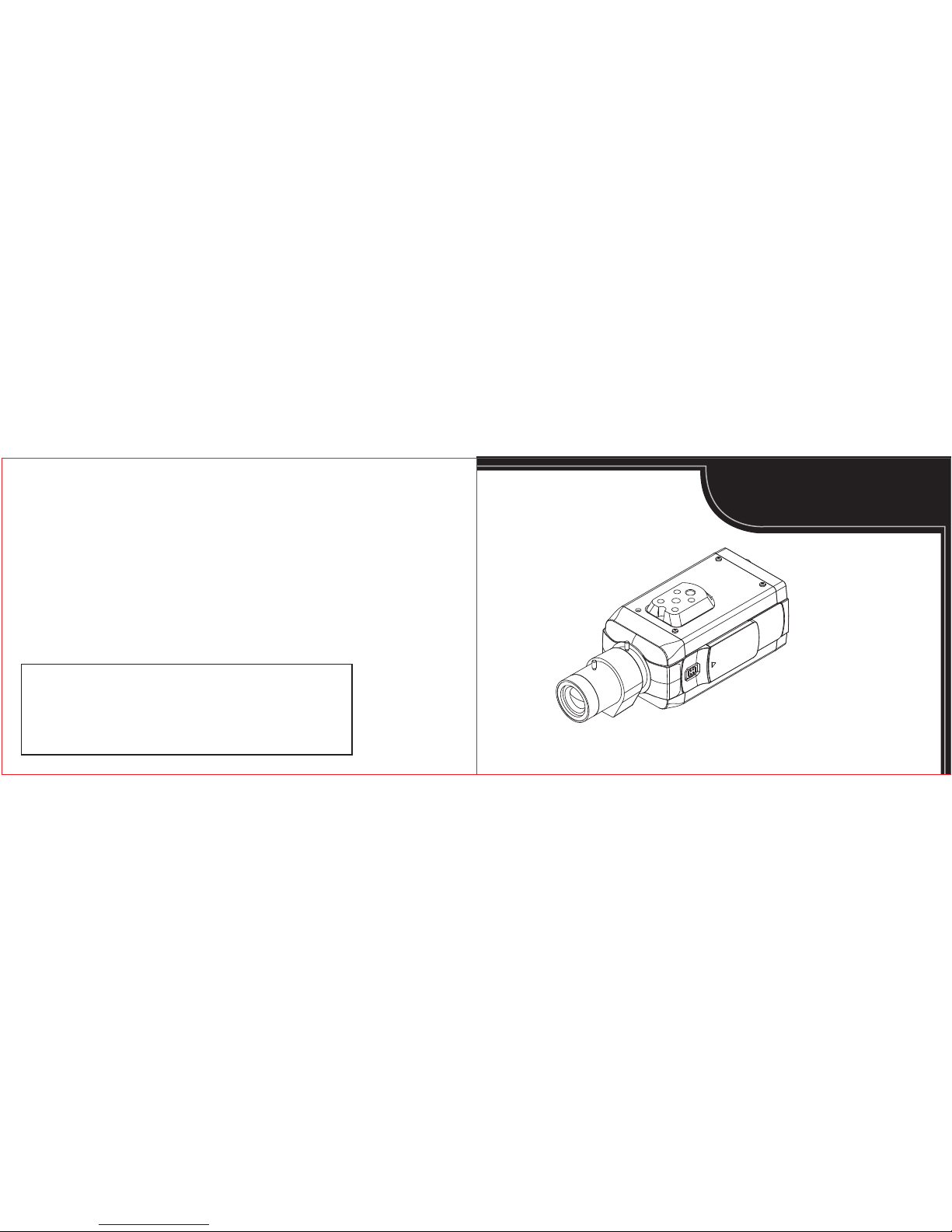
SUPREME IMAGE
Video Surveillance Camera
INSTRUCTION MANUAL
Distributed by
PRINTED IN KOREA
P/N : 388027030
Page 2
The lightning flash with an arrowhead symbol
within an equilateral triangle is intended to alert
the user to the presence of uninsulated
dangerous voltage within the product's enclosure
that may be of sufficient magnitude to constitute
a risk of electric shock to persons.
TO REDUCE THE RISK OF ELECTRIC SHOCK
DO NOT REMOVE COVER (OR BACK)
NO USER SERVICEABLE PARTS INSIDE
REFER SERVICING TO QUALIFIED
SERVICE PERSONNEL
REFER SERVICING TO QUALIFIED SERVICE PERSONNEL.
The exclamation point within an equilateral triangle
is intended to alert the user to the presence of
important operating and maintenance (servicing)
instructions in the literature accompanying
the product.
REGULATORY INFORMATION : FCC Part 15
WARNING -
Do not install this equipment in a confined
space such as a bookcase or similar unit.
Disposal of your old appliance
1.
When this crossed-out wheeled bin symbol
is attached to a product it means the product
is covered by the European Directive
2002/96/EC
2.
All electrical and electronic products should
be disposed of separately from the municipal
waste stream via designated collection fafilities
appointed by the government or the local
authorities
3. The correct disposal of your old appliance
will help prevent potential negative conse quences for the environment and human
health
4.
For more detailed information about disposal
of your old appliance, please contact your
city office, waste disposal service or the shop
where you purchased the product.
To disconnect power from the mains, pull out the mains
cord plug. When install the product, ensure that the plug
is easily accessible.
WARNING -
Wiring methods shall be in accordance with
the National Electric Code, ANSI/NFPA 70.
WARNING -
To reduce a risk of fire or electric shock, do
not expose this product to rain or moisture.
CAUTION -
This installation should be made by a qualified
service person and should conform to all local codes.
CAUTION -
To avoid electrocal shock, do not open the
cabinet. Refer servicing to qualified personnel only.
CAUTION -
To apparatus should not be exposed to
water (dripping or splashing) and no objects filled with
liquids, such as vases, should be placed on the apparatus.
WARNING - This is a class A product. In a domestic
environment this product may cause radio interference
in which case the user may be required to take adequate
measures.
CAUTION
RISK OF ELECTRIC SHOCK
DO NOT OPEN
CAUTION :
FCC WARING - This equipment may generate or use
radio frequency energy. Changes or modifications to
this equipment may cause harmful interference unless
the modifications are expressly approved in the instruction
manual. The user could lose the authority to operate this
equipment if an unauthorized change or modification is made.
This equipment has been tested and found to comply with
the limits for a Class A digital device, pursuant to Part 15
of the FCC Rules. These limits are designed to provide
reasonable protection against harmful interference when
the equipment is operated in a commercial environment
This equipment generates, uses, and can radiate radio
frequency energy and, if not installed and used in accordance
with the instruction manual, may cause harmful interference
to radio communications. Operation of this equipment
in a residential area is likely to cause harmful interference
in which case the user will be required to correct the
interference at his own expense.
- A suitable conduit entries, knock-outs or glands shall
be provided in the cable entries of this product in the
end use
-
Caution : Danger of explosion if battery is incorrectly
replaced. Replaced only with the same or equivalent
type recommended by the manufacturer. Dispose of
used batteries according to the manufacturer’s
instructions.
- Holes in metal, through which insulated wires pass,
shall have smooth well rounded surfaces or shall
be provided with brushings.
Page 3

1.
Read these instructions - All these safety and operating
instructions should be read before the product is operated.
2.
Keep these instructions - The safety, operating and user
instructions should be retainde for future reference.
3.
Heed all warnings - All warnings on the product and in
the operating instructions should be adhered to.
5.
Do not use this apparatus near water - For example :
near a bath tub, wash bowl, kitchen sink, laundry tub,
in a wet basement; near a swimming pool; etc.
6. Clean only with dry cloth - Unplug this product from
the wall outlet before cleaning. Do not use liquid cleaners.
7. Do not block any ventilation openings. Install in
accordance with the manufacturer’s instructions. -
Slots and openings in the cabinet are provided for
ventilation, to ensure reliable operation of the product,
and to protect it from overheating. The openings should
never be blocked by placing the product on a bed, sofa,
rug or other similar surface. This product should not
be placed in a built-in installation such as a bookcase
or rack unless proper ventilation is provided and the
menufacturer’s instructions have been adhered to.
8. Do not install near any heat sources such as
radiators, heat registers, stoves, or other apparatus
(including amplifiers) that produce heat.
4.
Follow all instructions - All operating and user instructions
should be followed.
9.
Do not defeat the safety purpose of the polarized or
grounding-type plug. A polarized plug has two blades
with one wider than the other. A grounding type plug
has two blades and a third grounding prong. The wide
blade or the third prong are provided for your safety.
If the provided plug does not fit into your outlet, consult
an electrician for replacement of the obsolete outlet.
10. Protect the power cord from being walked on or
pinched particularly at plugs, convenience receptacles,
and the point where they exit from the apparatus.
11.
Only use attachments/accessories specified by the
manufacturer.
12.
Use only with the cart, stand, tripod, bracket, or table
specified by the manufacturer, or sold with the
apparatus. When a cart is used, use caution when
moving the cart/apparatus combination to avoid injury
from tip-over.
13. Unplug this apparatus during lightning storms or
when unused for long periods of time.
14. Refer all servicing to qualified service personnel.
Servicing is required when the apparatus has been
damaged in any way, such as powersupply cord or
plug is damaged, liquid has been spilled or objects
have fallen into the apparatus, the apparatus has
been exposed to rain or moisture, does not operate
normally, or has been dropped.
04 05
IMPORTANT SAFETY INSTRUCTIONS IMPORTANT SAFETY INSTRUCTIONS
Page 4

06 07
CONTENTS FEATURE
- 1/3" Sony Super HAD Ⅱ CCD (Double scan)
- High Resolution 700 TV lines
- Day & Night (ICR)
- Wide Dynamic Range(x512)
- Adaptive Tone Reproduction – Expanded (ATR-EX)
- Digital Noise Reduction(2D+3D)
- High Light Compensation (HLC) Function
- Digital Image Stabilizer (DIS)
- Privacy mask Function
- Intelligent motion detection
- Intelligent Object detection
- On Screen Display
- Protocol
FEATURE ................................................................
CAUTIONS FOR SAFE OPERATION............................
PART NAMES AND FUNCTIONS................................
CONNECTIONS........................................................
MOUNTING THE LENS.............................................
DIFFERENT LENS TYPES.........................................
EXTERNAL DEVICE CONNECTIONS..........................
DAY & NIGHT FUNCTION SETTING...........................
INSTALLATION OF CAMERA....................................
MENU OPERATION..................................................
MAIN MENU............................................................
EXPOSURE..............................................................
WHITE BALANCE....................................................
IMAGE....................................................................
7p
8p
9p
13p
15p
17p
18p
19p
20p
21p
22p
23p
26p
27p
29p
31p
33p
34p
37p
INTELLIGENCE
.......................................................
SPECIAL FUNCTION...............................................
DISPLAY.................................................................
SPECIFICATIONS....................................................
DIMENSIONS..........................................................
Page 5

Power Supply
This camera must always be operated by a AC24V(Optional)
or DC12V Certified/Listed, class 2 power supply only.
Note : Line Lock only with AC 24V cameras will not
work with DC 12V.
Handling of unit
Be careful not to spill water or other liquids on the unit.
Be cautious not to get combustible or metallic material
inside the body. If used with foreign matter inside. the camera
is liable to fail or cause a fire or an electric shock.
Operating and storage
Do not point camera of view directly to light source(CCD
sensor will be damage). Avoid operating or storing the
unit in the following locations.
· Extemely hot or cold places (operating temperature
-10℃ ~ 50℃, however, we recommend that the
unit be used within a temperature range of 0℃ ~ 45℃)
· Assumes no wind chill factor
· Damp or dusty place
· Places exposed to rain
· Places subject to strong vibration
· Close to generators with powerful electromagnetic
radiation such as radio or TV transmitters.
Cleaning of the unit
· Remove dust or dirt on the surface of the lens with
a blower.
·
Use a dry soft cloth to clean the body. If it is very dirty,
use a cloth dampened with a small quantity of neutral
detergent, then wipe dry.
· Avoid the use of volatile solvents such as thinners,
alcohol, benzene, and insecticides.
They may damage the surface finish and / or impair
the operation of the camera.
【1】Lens mount cap
The cap is installed to protect the lens mount section.
Remove the lens mount cap before installing a lens.
(sold separately)
【2】Camera installation bracket
The bracket can be fixed at the top or bottom of
the camera. (page 20)
08 09
CAUTIONS FOR SAFE OPERATION
PART NAMES AND FUNCTIONS
【1】 【2】
Page 6
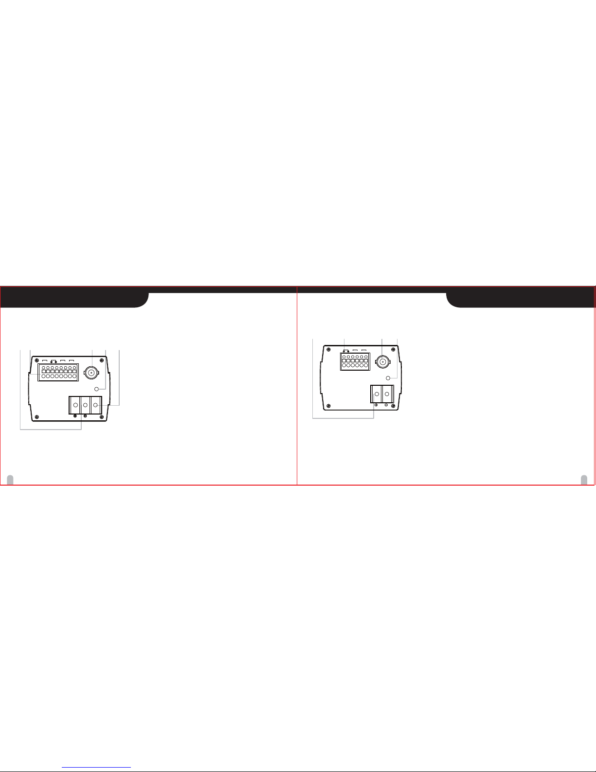
【3】Power input terminal
AC 24V or DC 12V input terminal
【4】External Device Connectors
· D&N
Connect the external swich to set the D&N
function manually.
· Alarm Output Terminal (ALARM OUT/COM)
Connect to the alarm output of an external device
· COMMUNICATION (COM)
Connect to an external controller
of RS-485 format.
· BALUN (UTP Terminal connector)
Transmission of video signals via a single UTP
(unshielded twisted pair)
【5】Video out(Type : BNC)
Connect this connector to a device such as a DVR
or monitor with a VIDEO IN connector.
【6】Power indicator
Comes on when the power to the camera is on.
【7】FG
10 11
PART NAMES AND FUNCTIONS PART NAMES AND FUNCTIONS
【6】【5】【7】【4】【3】
* DUAL TYPE (Optional)
【3】Power input terminal
DC 12V input terminal
【4】External Device Connectors
· D&N
Connect the external swich to set the D&N
function manually.
· Alarm Output Terminal (ALARM OUT/COM)
Connect to the alarm output of an external device
· COMMUNICATION (COM)
Connect to an external controller
of RS-485 format.
【5】Video out(Type : BNC)
Connect this connector to a device such as a DVR
or monitor with a VIDEO IN connector.
【6】Power indicator
Comes on when the power to the camera is on.
【6】【5】【4】【3】
* DC 12V TYPE
POWER
VIDEO OUT
RS-485
ALARM
D&N
GND
OUT
GND
EXT
DC12V
POWER
VIDEO OUT
RS-485
ALARM
D&N
GND
OUT
GND
EXT
BALUN
BAL(-)BAL(+)
DC12V/AC24V
FG
Page 7

Basic connection
The peripheral devices (DVR, monitor, lens, etc), AC/DC
adaptor and cables are not supplied.
1. Connecting the monitor.
Make the video signal connection between the camera
and the monitor or time lapse monitor or DVR.
2. Use a commercially available AC 24V / DC12V
adaptor.
Connect an AC 24V / DC 12V power source to the
AC 24V / DC 12V input terminal on the back of the
camera.
3. Insert the plug of this power cord into a wall outlet.
The POWER indicator will light. Adjust the picture on
the monitor using the Brightness and Contrast controls
etc.
To monitor’s Video Input
or Camera Input
12 13
PART NAMES AND FUNCTIONS CONNECTIONS
* DUAL TYPE (Optional)
【8】Buttons for menu
To set items on the MENU, use the these buttons
on the back panel. (page 21)
【9】ALC Lens Setting Switch
· DC : When you attach an Auto Iris lens requiring
the DC control signal, please put this switch in
the DC position.
·
Video : When you attach an Auto Iris lens requiring
the video control signal, please put this switch in
the VIDEO position.
【10】Lens iris output connector (LENS)
4-pin connector for Video or Auto iris lens
.
Note :
Lens selection can be DC or Video.
· DC : Direct Drive Lens
· Video : Video Drive Lens
*
Fixed Lens does not require Lens selection of DC or Video.
*
Refer to your Lens Manual for Instructions and Type
.
【10】
【9】【8】
1
2
3
DC12V/AC24V
FG
POWER
VIDEO OUT
RS-485
ALARM
D&N
GND
OUT
GND
EXT
BALUN
BAL(-)BAL(+)
DC12V/AC24V
FG
Page 8

14 15
1. Remove the lens mount cap from the camera.
2. Install the auto-iris lens.
2-1. Cs mount type lens
Carefully align the lens mount with the camera
opening, then turn the lens slowly to install it.
2-2. C mount type lens
To allow for flange-back adjustment, install the
C-mount adaptor (option) on the lens mount,
then carefully align the lens mount with the camera
opening and turn the lens slowly to install it.
3.
Connect the lens plug to the lens iris output connector
(LENS) on the side of the camera.
When using lenses from other makers, the plug shape
may not correspond to the terminal on the camera.
In such a case, remove the original plug and using a
soldering iron, connect a lens iris plug according to the
diagram. (Refer to next page.)
CONNECTIONS MOUNTING THE LENS
* DC 12V TYPE
Basic connection
The peripheral devices (DVR, monitor, lens, etc), AC/DC
adaptor and cables are not supplied.
1. Connecting the monitor.
Make the video signal connection between the camera
and the monitor or time lapse monitor or DVR.
2. Use a commercially available DC12V adaptor.
Connect a DC 12V power source to the DC 12V input
terminal on the back of the camera.
3. Insert the plug of this power cord into a wall outlet.
The POWER indicator will light. Adjust the picture on
the monitor using the Brightness and Contrast controls
etc.
To monitor’s Video Input
or Camera Input
1
2
3
DC12V
POWER
VIDEO OUT
RS-485
ALARM
D&N
GND
OUT
GND
EXT
DC12V
1
2-1
2-2
3
Page 9

Pin layout for the lens iris output connector
No.
1
2
3
4
DC type lenses
Damping -
Damping +
Drive +
Drive -
VIDEO type lenses
Vcc (+9V)
Not used
Video
Ground
Rewire the lens iris plug
1.
Cut off the plug of the lens cable, cut off approximately
8mm
of the insulation, and then strip approximately
2mm of the ends of the cable sheaths.
2.
Solder the ends of the cable wires to the ends of the
pins, and then attach the cover of the lens iris plug.
DC type auto-iris lens
A lens without a driver circuit can only operates on
a DC power source. In general, this type of lens is
referred to as DC type coil lens. (Set the ALC Lens
Setting Switch to the DC position.)
CAUTION : Depending on the type of lens used, the
lens may not perform properly.
VIDEO type auto-iris lens
A lens with amplifier circuit can operate on video
signal and DC power source. In general, this type
of lens is referred to as EE amplifier type lens.
ALC and LEVEL volume level controls are available
on the lens for iris adjustments. (Set the ALC Lens
Setting Switch to the VIDEO position.)
CAUTION :
Be careful not to use Auto Iris Lens with over 35mA.
16 17
MOUNTING THE LENS DIFFERENT LENS TYPES
8mm
2mm
Note :
Refer to your Lens for Instruction and Type.
Page 10

18 19
DAY&NIGHT FUNCTION SETTINGEXTERNAL DEVICE CONNECTIONS
D&N
GND
GND
EXT
EXT
D&N
GND
GND
EXT
EXT
You can set the D&N function manually.
Day function
When you open the external S/W, the D&N function is
set
to Day mode.
Night function
When you close the external S/W, the D&N function is set
to night mode.
Note :
If you use the external D&N function, you should set the
EXPOSURE /DAY&NIGHT option to EXT on the setup menu.
Open
External S/W
Close
External S/W
BALUN(Only Dual Type - Optional)
The cable allows for more versatile cabling, which
includes coupling signals from remote video cameras
to display systems, capture video, and to monitor other
security and surveillance applications
COMMUNICATION
Connect to an external controller of RS-485 format.
Motion Detector
When the Motion Detector function is working,
DC 3.3 V is outputted to OUT pin and GND pin.
Note :
Use a relay unit if the voltage or current of the connected
device exceeds the ratings.
DC12V
POWER
VIDEO OUT
RS-485
ALARM
D&N
GND
OUT
GND
EXT
DC12V
RS-485
ALARM
D&N
GND
OUT
GND
EXT
DC12V/AC24V
POWER
VIDEO OUT
RS-485
ALARM
D&N
GND
OUT
GND
EXT
BALUN
BAL(-)BAL(+)
DC12V/AC24V
FG
RS-485
ALARM
D&N
GND
OUT
GND
EXT
BALUN
BAL(-)BAL(+)
Page 11

20 21
This camera utilizes an on-screen user MENU. To set items
on the menu, use the following buttons on the side panel.
Up button : Moves the cursor upwards. Use this
button to select an item or adjust the parameters.
Down button : Moves the cursor downwards. Use
this button to select an item or adjust the parameters.
Right button : Moves the cursor to the right. Use
this button to select or adjust the parameters of
the selected item. The parameter changes each
time this button is pressed.
Left button : Moves the cursor to the left. Use this
button to select or adjust the parameters of the
selected item. The parameter changes each time
this button is pressed.
Set button : Executes selections and displays a
submenu for an item with the mark.
The bracket can be installed to either the top or bottom of
the camera
as desired. From changing the position of
the camera mounting bracket, you should always reuse
the screws that have been removed.
Note :
· Please use factory povided screws only.
· Camera mount and lens are not included(See your
local dealer).
INSTALLATION OF CAMERA MENU OPERATION
SET
Page 12
22
23
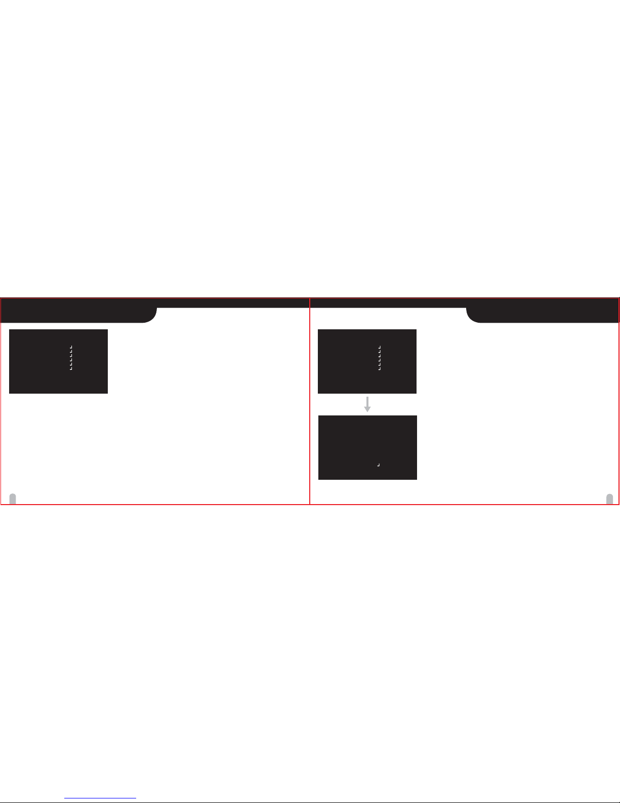
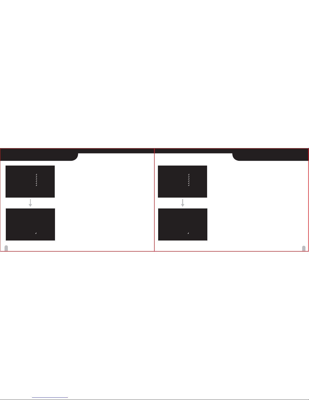
MAIN MENU
EXPOSURE
Functions can be setup using “Menu Key Command” of Visca protocol
or Menu Key Port input.
The menu consists of the “Main Menu” and “Sub Menu”.
The main menu is displayed where 7 camera functions can be selected.
To the right of each main menu selection, the sub-menu is displayed
If you want save the menu, select [SAVE].
If you want not save the menu, select [EXIT]
(After select , Power off -> on)
If you want default the menu, select [DFLT]
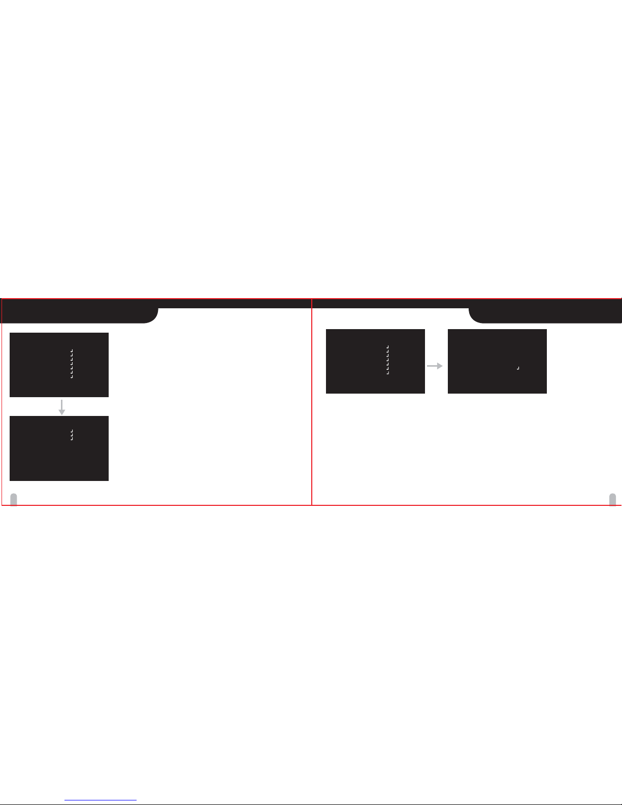
· MODEL : Select Model type of the “Auto Day&Night” function.
▶ TDN/COLOR : The “Auto Day&Night” function is performed according to the brightness level.
/ IR : The “Auto Day&Night” function is performed according to D/N-IN input.
· LENS : Select lens type
▶ DC / VIDEO / MANUAL
· MODE : Select exposure mode with Manual Lens
▶ AUTO / SHUT.P / MANUAL
· AGC : Select Auto Gain Control
▶ OFF / ON
▶ 0/2/4/6/8/10/12/14/16/18/20/22/24/26/28/30dB
(Manual Lens and Manual Exposure Mode)
· SHUT SPEED : Can be set in SHUT.P or MANUAL mode.
▶ NTSC : x512, x128, x64, x32, x16, x8, x4, x2, 1/60, 1/90, 1/100,
1/180, 1/250, 1/500, 1/1000, 1/1500, 1/2000, 1/5000, 1/10000,
1/20000, 1/50000, 1/100000 sec
PAL : x512, x128, x64, x32, x16, x8, x4, x2, 1/50, 1/80, 1/120,
1/150, 1/250, 1/500, 1/1000, 1/1500, 1/2000, 1/5000, 1/10000,
1/20000, 1/50000, 1/100000 sec
※ Slow shutter speed (x2 ~ x512) can be set in ELC MANUAL mode.
· DSS : Select Max DSS (Digital Slow Shutter)
▶ OFF / x2, x4, x8, x16, x32, x64, x128, x512
· FLICKERLESS : Select Flickerless mode
▶ OFF / ON (remove screen flicker)
[EXPOSURE]
LENS
MODE
AGC
SHUT SPEED
DSS
FLICKERLESS
BRIGHTNESS
WDR
BLC
DAY/NIGHT
[BACK] [SAVE] [DFLT]
[MENU]
MODEL
EXPOSURE
WHITE BAL
IMAGE
INTELLIGENCE
SPECIAL FUNC
DISPLAY
[EXIT] [SAVE] [DFLT]
TDN/COLOR
[MENU]
MODEL
EXPOSURE
WHITE BAL
IMAGE
INTELLIGENCE
SPECIAL FUNC
DISPLAY
[EXIT] [SAVE] [DFLT]
TDN/COLOR
DC
. . .
ON
. . .
OFF
OFF
8
OFF
OFF
Page 13
24
25
EXPOSURE EXPOSURE
· BRIGHTNESS : Adjust brightness level
▶ 1 (dark) ~ 15 (bright) steps
· WDR : Select WDR (Wide Dynamic Range)
▶ OFF / ON
▷LEVEL : Select the WDR brightness level
▶ 1 ~ 7 steps
▷ATR : Select the contrast level of dark area.
▶ LOW / MID / HIGH
· BLC : Select BLC (Back Light Compensation)
▶ OFF / ON
▷MODE : Select BLC mode
▶ AUTO / MANUAL
▷AREA# : Select BLC area
▶ 1 ~ 9 areas
▷LEVEL : Select manual BLC level
▶ LOW / MID / HIGH
· DAY&NIGHT : Select Day&Night
▷Mode : Select Day&Night mode
▶ DAY / NIGHT / AUTO / EXT (MODEL : TDN/COLOR)
▶ DAY / NIGHT / AUTO (MODEL : IR)
[EXPOSURE]
LENS
MODE
AGC
SHUT SPEED
DSS
FLICKERLESS
BRIGHTNESS
WDR
BLC
DAY/NIGHT
[BACK] [SAVE] [DFLT]
[MENU]
MODEL
EXPOSURE
WHITE BAL
IMAGE
INTELLIGENCE
SPECIAL FUNC
DISPLAY
[EXIT] [SAVE] [DFLT]
TDN/COLOR
DC
. . .
ON
. . .
OFF
OFF
8
OFF
OFF
▷Delay : Adjust the working time of the filter when Day&Night operated.
▶ 1 ~ 60 sec (MODEL : TDN/COLOR)
▶ LOW / MID / HIGH (MODEL : IR)
▷THRS : Day↔Night switching level in Auto Mode. (TDN/COLOR Model Only)
Switching in lower lux with higher threshold level.
▶ 1 ~ 29 steps
▷GAP : Margin between Day → Night switching level and Night
→ Day switching level. (TDN/COLOR Model Only)
▶ 1 ~ 5 steps
※ When you set up GAP too narrow, hunting might be happened.
▷BURST : You can burst off/on in Night mode
▶ OFF / ON
[EXPOSURE]
LENS
MODE
AGC
SHUT SPEED
DSS
FLICKERLESS
BRIGHTNESS
WDR
BLC
DAY/NIGHT
[BACK] [SAVE] [DFLT]
[MENU]
MODEL
EXPOSURE
WHITE BAL
IMAGE
INTELLIGENCE
SPECIAL FUNC
DISPLAY
[EXIT] [SAVE] [DFLT]
TDN/COLOR
DC
. . .
ON
. . .
OFF
OFF
8
OFF
OFF
Page 14

· MODE : Select white balance mode
▶ ATW / ONE PUSH / INDOOR / OUTDOOR / MANUAL / AUTO
▷ATW : Automatically adjusts color according to the available lighting.
▷ONE PUSH : It is a fixed white balance mode that may be
automatically readjusted only by pressing SET Button in
ONE PUSH mode.
▷OUTDOOR : Set color temperature to be Outdoor light (5400°K.)
▷INDOOR : Set color temperature to be Indoor light (3200°K.)
▷MANUAL : Color can be corrected when the user increases or
decreases ”Red Gain" or "Blue Gain".
▷ AUTO : Wide color temperature range (more ATW range)
· RED GAIN : Adjust R gain value
▶ 0 ~ 255 steps
· BLUE GAIN : Adjust B gain value
▶ 0 ~ 255 steps
· CHROMA : Select the chroma level
▶ LOW / MID / HIGH
[WHITE BALANCE]
[BACK] [SAVE] [DELT]
MODE
RED GAIN
BLUE GAIN
CHROMA
ATW
. . .
. . .
MID
26 27
WHITE BALANCE
· HLC : Enhances the visibility on strong light sources in dark locations
▷ MODE : Select the HLC mode
▶ OFF / ON
▷ LEVEL : Select the HLC brightness level
▶ LOW / MID / HIGH
▷ CLIP LEVEL : You can adjust the HLC threshold level.
Block area is to be more sensitivity with lower level.
▶ 1 ~ 7 steps
· DNR : On screen digital noise reduction
▶ OFF
/ 1 ~ 10 (Select noise reduction level)
/ Auto (DNR level is adjusted automatically)
· HR : Select high resolution
▶ OFF / 1 ~ 7
· MIRROR : Select a flip mode
▶ OFF
/ V (You can flip the picture vertically on the screen)
/ H (You can flip the picture horizontally on the screen)
/ H&V (You can flip the picture horizontally & vertically on the screen)
· SHARPNESS : Adjust sharpness level
▶ 1 ~ 16 steps
IMAGE
[BACK]
[SAVE]
[DFLT]
[IMAGE]
HLC
DNR
HR
MIRROR
SHARPNESS
EFFECT
FREEZE
E.ZOOM
[MENU]
MODEL
EXPOSURE
WHITE BAL
IMAGE
INTELLIGENCE
SPECIAL FUNC
DISPLAY
[EXIT] [SAVE] [DFLT]
TDN/COLOR
[MENU]
MODEL
EXPOSURE
WHITE BAL
IMAGE
INTELLIGENCE
SPECIAL FUNC
DISPLAY
[EXIT] [SAVE] [DFLT]
TDN/COLOR
AUTO
3
OFF
8
OFF
OFF
OFF
Page 15

· PRIVACY : Hide an area you want to hide on the screen
▶ MASK# : Select mask area number (1 ~ 16)
▶ ACT : Mask enable or disable (OFF / ON)
▶ COLOR : Select mask color (1 ~ 14)
▶ TRANSPARENCY : Select mask transparency level (0 ~ 3)
▶ POSITION : Adjust the mask position
▶ SIZE : Adjust the mask size
▶ MOSAIC : Mosaic display (OFF / ON)
▶ MOSAIC TYPE : Mosaic roughness setting (1 ~ 8)
· MOTION : When there is movement of the subject in the screen,
there will be an motion detection
▶ MODE : MD function enable or disable (OFF / ON)
▶ AREA# : Select MD area number (1 ~ 3)
▶ ACT : Activate or deactivate the each MD Area (OFF / ON)
▶ SENSITIVITY : Adjust sensitivity of MD (1 ~ 20)
▶ INTERVAL TIME : Select the alarm interval time (1 ~ 256sec)
▶ DWELL TIME : Select the duration time about changing MD mode
(1 ~ 256sec)
▶ POSITION : Adjust the MD position
▶ SIZE : Adjust the MD size
[BACK]
[INTELLIGENCE]
PRIVACY
MOTION
OBJECT
[MENU]
MODEL
EXPOSURE
WHITE BAL
IMAGE
INTELLIGENCE
SPECIAL FUNC
DISPLAY
[EXIT] [SAVE] [DFLT]
TDN/COLOR
[BACK]
[SAVE]
[DFLT]
[IMAGE]
HLC
DNR
HR
MIRROR
SHARPNESS
EFFECT
FREEZE
E.ZOOM
[MENU]
MODEL
EXPOSURE
WHITE BAL
IMAGE
INTELLIGENCE
SPECIAL FUNC
DISPLAY
[EXIT] [SAVE] [DFLT]
TDN/COLOR
AUTO
3
OFF
8
OFF
OFF
OFF
28 29
IMAGE INTELLIGENCE
· EFFECT : Select the negative or B/W effect
▶ OFF / NEGATIVE / B/W
· FREEZE : Select real or still mode
▶ OFF / ON
· E.ZOOM : Select maximum digital zoom magnification.
▶ OFF / ON (max x2 ~ x19, x21, x23, x25, x28, x32)
▷ ZOOM : Adjust Digital Zoom Position
▷ PAN : Adjust Digital Pan position
▷ TILT : Adjust Digital Tilt position
Page 16
30 31
INTELLIGENCE SPECIAL FUNCTION
· OBJECT : Detect object appeared or removed the screen
▶ MODE : Object detection enable or disable (OFF / ON)
▶ AREA# : Select OD Area number (1 ~ 9)
▶ SENSITIVITY : Adjust sensitivity (1 ~ 5)
▶ DWELL TIME : Select the duration time about changing OD mode
(1 ~ 256sec)
· SYNC MODE : Select vertical sync source
▶ INT (Internal Sync) / LL (External sync)
· PHASE : Adjust external sync phase
▶ NTSC : 0 ~ 131 steps
PAL : 0 ~ 156 steps
· DIS : Select the DIS (Digital Image Stabilizer) mode
▶ OFF / ON
※ E.Zoom, Motion & Object detection could not turn on while DIS function is working.
· DEFECT DET : Executes white pixel compensation.
▶ ONE PUSH↲
※ When you use the manual lens, you have to block the lens for blocking lights into the lens.
· DEFECT LEVEL : The Threshold level of white pixel compensation.
▶ 1 ~ 20
[BACK] [SAVE] [DFLT]
[SPECIAL FUNC]
SYNC MODE
PHASE
DIS
DEFECT DET
DEFECT LEVEL
SCENE MODE
COMM
[BACK]
[INTELLIGENCE]
PRIVACY
MOTION
OBJECT
[MENU]
MODEL
EXPOSURE
WHITE BAL
IMAGE
INTELLIGENCE
SPECIAL FUNC
DISPLAY
[EXIT] [SAVE] [DFLT]
TDN/COLOR
[MENU]
MODEL
EXPOSURE
WHITE BAL
IMAGE
INTELLIGENCE
SPECIAL FUNC
DISPLAY
[EXIT] [SAVE] [DFLT]
TDN/COLOR
INT
...
OFF
ONE PUSH
1
USER
Page 17

32 33
SPECIAL FUNCTION DISPLAY
· DISP SEL : Select display item.
▶ OFF / ON
▶ ID : OFF / ON
▶ TITLE : OFF / ON
▶ ZOOM RATIO : OFF / ON
· SET TITLE : Select camera title menu (Text edit)
· LANGUAGE : Select language
▶ ENGLISH / KOREAN / CHINESE
· SETUP STATUS : Shows the current OSD Menu setup status and
compare the each values with the ones in Factory default.
AE
D&N
AWB
Mode
WDR
DSS
Mode
Burst
Mode(Day)
Mode(Night)
Auto Auto Auto Auto Auto
OFF OFF ON OFF OFF
Max 4x Max 2x Max 4x Max 4x Max 4x
Auto Auto Day Auto Day
OFF ON OFF OFF OFF
ATW Auto Auto Auto Auto
ATW ATW Auto ATW Auto
Function Normal Traffic Back Day/ Casino
Light Night
· COMM : Set up the camera ID, baud rate, protocol
▷ID : Select the camera ID
▶ 1 ~ 255
▷BAUD RATE : Select serial communication speed
▶ 2400 / 4800 / 9600 / 19200 / 38400 / 57600 / 115200 bps
▷PROTOCOL : Select operating protocol
▶ VISCA / Pelco-D / Pelco-P
[BACK] [SAVE] [DFLT]
[DISPLAY]
DISP SEL
SET TITLE
LANGUAGE
SETUP STATUS
[MENU]
MODEL
EXPOSURE
WHITE BAL
IMAGE
INTELLIGENCE
SPECIAL FUNC
DISPLAY
[EXIT] [SAVE] [DFLT]
TDN/COLOR
· SCENE MODE : Select scene preset
▶ USER / NORMAL / TRAFFIC / BACK LIGHT/ DAY/NIGHT / CASINO
ENGLISH
ON
Page 18

34 35
SPECIFICATIONSSPECIFICATIONS
PAL
NTSC
Model
Image Sensor
Total Pixels
Scanning system
Scanning Frequency
Sync. System
Resolution
Min. illumination
Video Output
S/N Ratio
Exposure
Lens
Gain Control
Shutter Speed
Digital Slow Shutter
Flickerless
Brightness
1028(H) × 508(V)
15.734KHz(H),59.94Hz(V)
1/60 ~ 1/100,000 sec 1/50 ~ 1/100,000 sec
1028(H) x 596(V)
15.625KHz(H),50Hz(V)
1/3" SONY Super HADⅡ(Double Scan) CCD
2:1 Interlace
Internal / External (V-Lock)
Max 700 TV lines in color @ HR 7 mode
(750TV lines in B/W @ HR 7 mode)
Color : 0.3 lux , BW : 0.1 lux
Color DSS : 0.0005 lux , BW DSS : 0.0002 lux
1.0 Vp-p (75 ohm, composite)
more than 50dB (AGC off)
Auto / Shutter PRI / Manual
DC / Video / Manual
Off / On (Max 30dB)
Off / Max x2 ~ x512
Off / On
1 ~ 15 steps
PAL
NTSC
Model
WDR
BLC
Day&Night
White Balance
Chroma
Image
HLC
DNR
HR
Mirror
Sharpness
Effect
Freeze
E.Zoom
Intelligent
Privacy Mask
Motion Detection
Object Detection
Off / On
Off / On
Day / Night / Auto / Ext
ATW / One Push / Indoor / Outdoor / Manual / Auto
Low / Mid / High
HLC / DNR / HR / Mirror / Sharpness / Effect / Freeze / E.Zoom
Off / On
Off / Manual / Auto
Off / 1 ~ 7 steps
Off / V / H / H&V
1 ~ 16 steps
Off / Negative / B/W
Off / On
E-Zoom (Max x2 ~ x32) / E-Pan / E-Tilt
Privacy / MD / OD
Off / 16 positions
Off / 3 positions
Off / On
Page 19

36 37
SPECIFICATIONS DIMENSIONS
PAL
NTSC
Model
Special
Sync Mode
Phase
DIS
Defect Det
Scene Mode
Comm
Display
Disp Sel
Language
Power Source
Power Consumption
Power Input
Video Output
Operating Temperature
Operating Humidity
Storage Temperature
Sync / Phase / DIS / Defect Det / Scene Mode / Comm
INT / LL
Off / On
One Push
User / Normal / Traffic / Back Light / Day/Night / Casino
Baud Rate : 2400 / 4800 / 9600 / 19200 / 38400 / 57600 / 115200
Protocol : VISCA / Pelco-D / Pelco- P
Disp Sel / Set Title / Language / Setup Status
ID / Title / Zoom Ratio
English / Chinese / Korean
DC12V±10%
200mA
Connector
Connector
-10℃ ~ +50℃
0 ~ 86% (non-condencing)
-20℃ ~ +60℃
0 ~ 131 steps 0 ~ 156 steps
2- 1/4"-20 UNC
POWER
VIDEO OUT
RS-485
ALARM
D&N
GND
OUT
GND
EXT
DC12V
44.5
14
71
54.2
61.4
132
* DC 12V TYPE
Page 20

38 39
DIMENSIONS MEMO
* DUAL TYPE (Optional)
2- 1/4"-20 UNC
POWER
VIDEO OUT
RS-485
ALARM
D&N
GND
OUT
GND
EXT
BALUN
BAL(-)BAL(+)
DC12V/AC24V
FG
71
54.2
61.4
132
 Loading...