


CVM-WM300
UHF Wireless Microphone
USER MANUAL

Foreword
Thanks for purchasing COMICA WM300 UHF wireless microphone.
WM300 is an all-metal wireless microphone with dual-transmitter triggered by one receiver, with built-in polymer lithium battery, it utilizes UHF wireless FM technology and LCD high-resolution lattice screen,16-level adjustable volume, and integrated into LCF Low cut filter) , Auto-scanning, Auto IR Channel-match, stereo / mono switchable audio mode, RF signal strength adjustment, MIC/LINE IN input dual selection, power monitoring at receiver end, sound pickup dynamic display, backlight adjustment and other functions, at the same time with strong shielding anti-noise performance, it’s a high-quality microphone to broadcasting level;
To ensure the smooth use and safety of the product, please carefully read this instruction before using and properly assemble and operate.
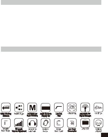
Main Features
. Dual Transmitters Triggered by One Receiver, A/B Double Group Options;
. Used for Multiple Devices Working Together;
. Working Distance is Up to 120m (120m in Open Area, 80m in Barrier Area);
. LCF Low Cut Filtering Mode;
. Auto-scanning for Quick Channel Selection;
. Manual or Auto IR Sync;
. Optional Language;
. Adjustable RF Signal Strength;
. Audio Dynamic Display Bar;
. 16 Levels Volume Adjustment;
. Transmitter Power Monitor;
. Mono/Stereo Switchable Output Modes;
. Built-in Rechargeable Lithium Battery, Slim Body;
. Low-consumption, Super-long Standby Time;
. Lattice LCD Display, High Resolution;
. Full Metal Manufacturing, Excellent Shielding;
1
Notice
 Transmitter should be more than 20cm from Receiver, when the distance is less than 20cm, Receiver’s wireless signal receiving part will take protect action to shut down the receiving of wireless signal, then audio may be intermittent, which is normal;
 When using auto IR sync, please stay within one meter, otherwise the signal may be too weak and the sync will not be successful;
 In the case of stereo/mono mode switch, please preset the mode before using to avoid the transient interference caused by switching during usage;
 The antenna will affect the working distance. Please protect the antenna and avoid any man-made damage;
 The working distance will be affected by the surrounding environment. Please try to keep the environment open without interference during usage, and close the WIFI of the device itself;
 When using this product in a short distance, it is recommended to set RF strength at ‘LOW’ to reduce the power consumption;
 For smart phone shooting, customers must separately purchase a TRS-TRRS audio converting cable,and pay attention to set the mobile phone mode to 'Flight Mode' to avoid incoming call interference;
(It does not support the original recording system of some android systems, the third-party APP is recommended to be used in this case);
 Please keep this product in dry environment;
Do not expose the device in rain or humid environment, otherwise there will be a danger of short circuit;
Package Contents
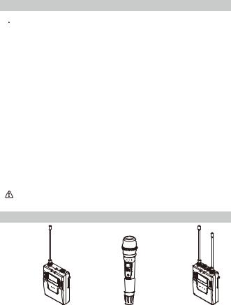
Main Parts
2 |
Lavalier Transmitter (TX) |
Hand-held Transmitter (HTX) |
Receiver (RX) |
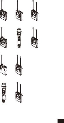
Multiple Selections:
WM300(A) = 2TX + RX
WM300(B) = TX + HTX + RX
WM300(C) = TX + RX
WM300(D) = HTX + RX
|
+ |
+ |
TX |
TX |
RX |
|
+ |
+ |
TX |
HTX |
RX |


 +
+
TX RX
+
HTX RX
3
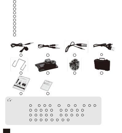
Accessories:
13.5mm Mic Audio Input Cable
23.5mm-3.5mm Audio Output Cable
33.5mm-XLR Audio Output Cable
4Micro USB Charging Cable
5Belt Clip
6Hot-shoe Mount
7Wind Muff
8Portable Box
9User Manual
10 Warranty Card
1 2 3 4
5 6 7 8
9 10
The accessories of each combination include |
|
|
|||||||||||
WM300(A)= |
1 |
x2 + 2 + |
3 + 4 x2 + |
5 x3 + |
6 + |
7 x2 + 8 + 9 + 10 |
|||||||
WM300(B)= |
1 |
+ |
2 |
+ 3 |
+ 4 |
+ 5 |
x2 + |
6 |
+ 7 |
+ 8 |
+ 9 |
+ 10 |
|
WM300(C)= |
1 |
+ |
2 |
+ |
3 |
+ 4 |
+ 5 |
x2 + |
6 |
+ 7 |
+ 8 |
+ 9 |
+ 10 |
WM300(D)= |
2 |
+ 3 |
+ |
4 |
+ 5 |
+ 6 |
+ 8 |
+ 9 + 10 |
|
|
|||
4
|
Components and Instruction |
|
|
Components |
|
|
|
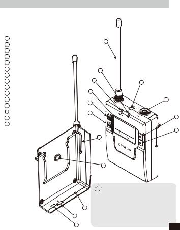
Lavalier Transmitter (TX) |
|
|
|
1 |
Antenna |
1 |
|
2 |
Matching Status Indicator Light |
|
|
|
|
||
3 |
Sound Status Indicator Light |
|
|
4 |
LCD Screen |
|
|
5 |
Power / Muting Button |
|
|
6 |
SET Function Button |
2 |
|
7 |
IR Sensor |
|
7 |
8 |
MIC / LINE IN External Input |
3 |
|
|
|
|
|
9 |
Function Selection Button + |
4 |
|
10 |
Function Selection Button - |
|
|
|
|
||
11 |
Belt Clip |
5 |
8 |
12 |
1/4 Mounting Hole |
|
|
|
|
||
13 |
Charging Indicator |
6 |
|
14 |
Micro USB Charging Socket |
|
9 |
15 |
Reset Hole |
|
|
|
|
|
10 |
|
|
11 |
|
|
|
12 |
|
14
15
The function of reset hole: when function program of the product is disorganized and unable to make normal adjustment or even
13shutdown, you can use an appropriate taper tool to insert the reset hole to realize the function
reset. 5
1
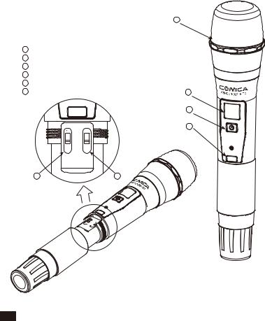
Hand-held Transmitter (HTX)
1 Microphone
2LCD Display
3Power / Muting Button
4IR Screen
5 |
Low cut/Normal Audio Switch |
|
6 |
Signal Strength “High/Low” Switch |
2 |
|
|
3 |
|
|
4 |
|
High |
|
-Low
LCF RF
5 |
6 |
 LCF
LCF 


RF
6
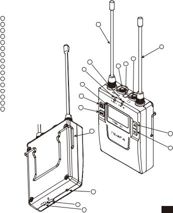
Receiver (RX)
1Group A Antenna
2Group B Working Status Indicator Light
3Group A Working Status Indicator Light
4LCD Screen
5Power Switch
6 SET Function Button
73.5mm Audio Output Socket 
8IR Sensor
9 |
3.5mm Monitoring Socket |
3 |
|
10 |
Group B Antenna |
||
|
|||
11 |
Function Selection Button + |
|
|
12 |
Function Selection Button - |
4 |
|
13 |
Belt Clip |
|
|
14 |
Charging Indicator |
5 |
|
15 |
Micro USB Charging Socket |
6 |
|
16 |
Reset Hole |
1
10
9
2 |
7 |
8 |
|
||
|
|
13 |
11 |
|
|
|
12 |
14
15 |
7 |
16 |
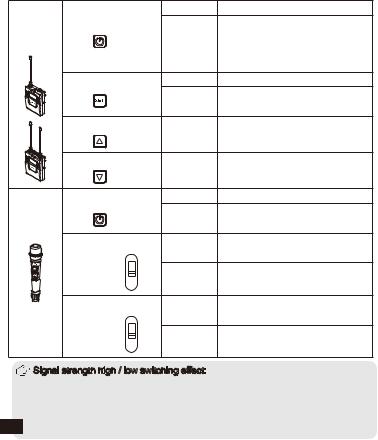
Function Button Instruction
Lavalier |
|
|
Long Press |
Power On / Off |
Power / Muting Button |
|
Muting Mode This function is only |
||
Transmitter |
Short Press |
|||
/ Receiver |
|
|
for transmitter, when the mute |
|
|
|
|
function is turned on and the |
|
|
|
|
|
|
|
|
|
|
screen is lighted up |
|
SET Function Menu |
Long Press |
Enter the function adjustment menu |
|
|
|
1.Confirm the selected function |
||
|
|
|
Short Press |
|
|
|
|
|
2.Exit the function adjustment menu |
|
+ Button |
|
Short Press |
Function Adjustment (+) |
|
|
|
||
|
- Button |
|
Short Press |
Function Adjustment (-) |
|
|
|
||
Hand-held |
Power / Muting Button |
Long Press |
Power On / Off |
|
Transmitter |
|
|
Short Press |
Muting Mode Only goes into |
|
|
|
|
effect when the screen lights up |
|
“Low cut/ Normal” |
Push-up |
Low cut |
|
|
Sound Switch |
|
|
|
|
|
- |
Push-down |
Normal |
|
|
LCF |
|
|
|
Signal Strength |
Push-up |
Signal strength--high |
|
|
“High/Low” |
High |
|
|
|
Switch |
Low |
Push-down |
Signal strength--low |
|
|
RF |
|
|
|
Signal strength high / low switching effect: |
|
With high signal strength, the wireless working distance is up to 80-120M, high |
|
power consumption, battery life is short; With low signal strength, the wireless |
8 |
working distance is up to 30-60M, low power consumption, the battery can be |
used for a long time. |
 Low
Low
 cut function:
Appropriately remove the low frequency part of the sound, reduce the ambient noise of the low frequency part, to make sound more clean and clear.
Indicator Light Instruction
|
|
|
Normal Recording Status |
|
|
|
|
This state is only for the |
|
|
|
Green Light Keeps On |
transmitter, when the |
|
|
|
channel matches |
||
|
|
|
||
|
|
|
successfully, the receiver |
|
Transmitter |
AUDIO |
|
can pick up the sound |
|
|
|
|
||
|
|
|
|
|
|
|
Red Light Keeps On |
Muting Mode |
|
|
|
Red Light Flicker |
Low-power reminder |
|
|
|
|
Channel matches |
|
|
|
Green Light Keeps On |
No matter the channel |
|
|
IR |
|
matches or not |
|
|
|
|
||
|
|
Red Light Flicker |
Channel in the match... |
|
|
|
only for IR Sync |
||
|
|
|
||
|
|
|
|
|
|
|
Green Light Keeps On |
Normal working status after |
|
|
|
the channel matches |
||
|
|
|
||
|
|
|
|
|
|
A IR/RF |
Green Light Flicker |
Channel doesn’t match |
|
Receiver |
|
Channel in the match... |
||
|
|
|||
B IR/RF |
Red Light Flicker |
only for IR Sync |
||
|
||||
|
|
|
|
|
|
|
|
Low-power reminder |
|
|
|
Red light keeps on |
Channel closed |
|
|
|
|
|
 A IR/RF Group A Working Status Indicator
B IR/RF Group B Working Status Indicator
9
Installation and Usage
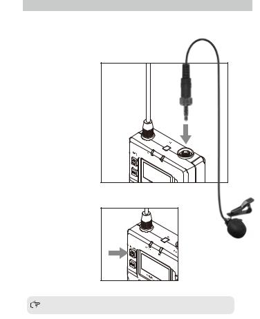
Lavalier Transmitter
1. Insert the 3.5mm audio input line into MIC socket
2. Long press the power button to turn on the transmitter
3. After the channel matching with the receiver, it can be used |
|
Please refer to screen operation instruction for channel matching. |
|
10 |
||
|
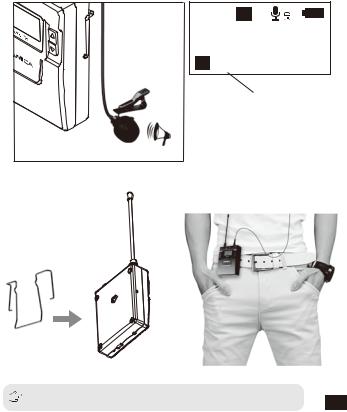
3.Connect the MIC to the audio source and check the working status according to the volume indicator on the screen
 H A
H A
G r o u p A
C H11 523 . 300MHz
A 
Audio Dynamic Display Bar
4. Connect the belt clip to the connection hole
5. After the channel matching with the receiver, it can be used
Please refer to screen operation instruction for channel matching. |
11 |
|
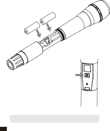
Hand-held Transmitter
1. Install two AA batteries into the battery tray according to the positive and negative electrode
A
A
A
A
2.Long press the button switch to turn on the hand-held transmitter
3. After the channel matching with the receiver, it can be used
 Please refer to screen operation instruction for channel matching.
12
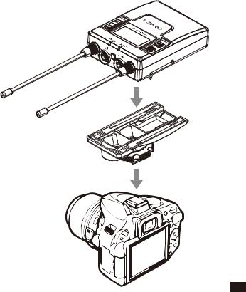
Receiver
1. Connect the receiver to the video device through the hot-shoe
13
 Loading...