

Page 1

Page 2

CONTENTS
INTRODUCTION
WARNINGS ..........................................................................................................4
MONITOR DESCRIPTION ...................................................................................5
KEY FUNCTIONS ................................................................................................5
PLANUX MANAGER MENU ................................................................................6
LIGHTS
LIGHTS MENU DESCRIPTION ...........................................................................7
LIGHT CONTROL.................................................................................................7
LIGHT SCHEDULING FOR AN AREA ..................................................................8
DIMMER LIGHT SCHEDULING ...........................................................................9
LIGHT SCHEDULING ..........................................................................................10
OTHER
OTHER MENU DESCRIPTION ............................................................................11
LOAD CONTROL .................................................................................................11
LOAD SCHEDULING ...........................................................................................12
LOAD SCHEDULING FOR AN AREA ..................................................................13
SHUTTERS
SHUTTERS MENU DESCRIPTION .....................................................................14
SHUTTER CONTROL ..........................................................................................14
SHUTTER SCHEDULING ....................................................................................15
SHUTTER SCHEDULING FOR AN AREA ........................................................... 16
AUTOMATION
AUTOMATION MENU DESCRIPTION .................................................................17
AUTOMATION SCHEDULING .............................................................................18
IRRIGATION
IRRIGATION MENU DESCRIPTION ....................................................................19
IRRIGATION SCHEDULING ................................................................................20
CLIMATE
CLIMATE MENU DESCRIPTION .........................................................................21
CLIMATE CONTROL ............................................................................................21
CLIMATE SCHEDULING ......................................................................................22
MANUAL CLIMATE MODE...................................................................................23
CLIMATE FORCING .............................................................................................23
LOADS
LOADS MENU DESCRIPTION ............................................................................24
CONSUMPTION
CONSUMPTION MENU DESCRIPTION .............................................................25
KEY TO THRESHOLD COLOURS .......................................................................25
DOOR ENTRY MONITORS
ANSWERING A CALL ..........................................................................................26
DOOR ENTRY MONITORS MENU DESCRIPTION ............................................26
VIDEO MEMORY .................................................................................................26
VIEWING A RECORDING ....................................................................................27
DELETING A RECORDING..................................................................................27
HANDS-FREE ......................................................................................................27
SETTING MELODIES ..........................................................................................27
ADJUSTING THE VOLUME .................................................................................28
ACTUATORS ........................................................................................................28
RENAMING ACTUATORS ...................................................................................29
CAMERAS ............................................................................................................29
RENAMING CAMERAS .......................................................................................30
INTERCOMS ........................................................................................................31
RENAMING INTERCOMS....................................................................................31
SETUP
SETUP MENU DESCRIPTION ............................................................................32
LANGUAGE..........................................................................................................32
LOCKING THE KEYPAD AND T OUCH-SCREEN ................................................32
SETTING THE DATE & TIME...............................................................................33
INFORMATION .....................................................................................................33
CONDITIONS .......................................................................................................33
SETUP - CONSUMPTION
CONSUMPTION SETUP MENU DESCRIPTION ................................................34
TOOLBAR ............................................................................................................34
CURRENCY .........................................................................................................35
DISPLAY ...............................................................................................................35
Page 3

RATES ..................................................................................................................36
THRESHOLDS .....................................................................................................37
CLEAR..................................................................................................................37
SETTINGS............................................................................................................38
UNIT OF MEASUREMENT ..................................................................................38
PULSES ...............................................................................................................38
STEP ....................................................................................................................39
SCALE FACTOR ..................................................................................................39
ADVANCED
ACCESSING ADVANCED MENUS ......................................................................40
ADVANCED MENUS DESCRIPTION ..................................................................40
KEY PROGRAMMING .........................................................................................41
VIDEO MEMORY SETUP ....................................................................................42
ACTUATORS ........................................................................................................42
ADDING ACTUATORS .........................................................................................42
MODIFYING AN ACTUATOR CODE ....................................................................43
DELETING ACTUATORS .....................................................................................43
CAMERAS ............................................................................................................44
ADDING CAMERAS .............................................................................................44
MODIFYING A CAMERA CODE...........................................................................45
DELETING CAMERAS .........................................................................................45
INTERCOMS ........................................................................................................46
ADDING AN INTERCOM......................................................................................46
MODIFYING AN INTERCOM ADDRESS .............................................................47
DELETING AN INTERCOM..................................................................................47
SELECTIVE INTERCOM......................................................................................48
ADDING A SELECTIVE INTERCOM....................................................................48
DELETING / MODIFYING A SELECTIVE INTERCOM ........................................49
ADDRESSES MENU DESCRIPTION ..................................................................49
SETTING THE BRACKET CODE ........................................................................49
SETTING A MONITOR AS MAIN / SECONDARY ................................................50
SETTING A MULTIPLE ADDRESS ......................................................................50
SETTING THE INTERCOM ADDRESS ...............................................................50
CALIBRATING THE TOUCH-SCREEN ................................................................51
SET INPUT ...........................................................................................................51
TOTAL RESET .....................................................................................................51
RESET CONFIGURATIONS ................................................................................52
CONFIGURATION UPDATE ................................................................................52
PRODUCT UPDATE ............................................................................................52
TRANSMISSION TIME .........................................................................................52
NUMBER OF TRANSMISSIONS .........................................................................52
PLANUX MANAGER SETTINGS FOR VEDO SERIES CONTROL UNITS .........53
ALARM
ALARMS MENU DESCRIPTION..........................................................................54
AREA STATUS LEGEND .....................................................................................54
FULLY ARMING THE ANTI-INTRUSION SYSTEM..............................................55
FULLY DISARMING THE ANTI-INTRUSION SYSTEM .......................................56
ACTIVATING THE ALARM FOR AN AREA ..........................................................57
DEACTIVATING THE ALARM FOR AN AREA .....................................................58
DISPLAYING THE ALARM ZONE ........................................................................59
RESETTING THE ALARM ST ATUS .....................................................................60
RESETTING THE ALARM MEMORY...................................................................61
MANAGING USERS.............................................................................................62
ADDING USERS ..................................................................................................63
MODIFYING THE USER PASSWORD ................................................................63
DELETING USERS ..............................................................................................64
SYSTEM TEST .....................................................................................................64
ALARM LOG.........................................................................................................65
ALARM LOG LEGEND .........................................................................................66
SCENARIOS
SCENARIOS MENU DESCRIPTION ...................................................................67
CREATING NEW SCENARIOS ............................................................................67
SCHEDULING SCENARIOS ................................................................................69
ACTIVATING SCENARIOS ..................................................................................70
DELETING SCENARIOS .....................................................................................71
MODIFYING SCENARIOS ...................................................................................72
KEY MENU DESCRIPTION .................................................................................73
REGISTERING NEW KEYS .................................................................................74
DELETING KEYS .................................................................................................75
RENAMING KEYS................................................................................................76
MODIFYING KEY FUNCTIONS ...........................................................................76
ACTIVATING SCENARIOS USING A KEY ...........................................................78
Page 4

INTRODUCTION
4
INTRODUCTION
WARNINGS
Comelit Group S.p.A. declines any responsibility for improper use of the apparatus, for any alterations made
by others for any reason, and for the use of non-original accessories or materials.
Caution! In order to reduce the risk of faults and electric shocks:
• Do not open the apparatus or carry out any repairs yourself. If necessary, request the services of qualifi ed
personnel.
• Do not insert objects or pour liquids into the device.
• Clean using a damp cloth. Do not use alcohol or other aggressive products.
Fonts are (c) Bitstream (see below). DejaVu changes are in public domain.
Glyphs imported from Arev fonts are (c) Tavmjong Bah (see below)
Bitstream Vera Fonts Copyright
-----------------------------Copyright (c) 2003 by Bitstream, Inc. All Rights Reserved. Bitstream Vera is a trademark of Bitstream, Inc.
Permission is hereby granted, free of charge, to any person obtaining a copy of the fonts accompanying
this license ("Fonts") and associated documentation fi les (the "Font Software"), to reproduce and distribute
the Font Software, including without limitation the rights to use, copy, merge, publish, distribute, and/or sell
copies of the Font Software, and to permit persons to whom the Font Software is furnished to do so, subject
to the following conditions:
The above copyright and trademark notices and this permission notice shall be included in all copies of one
or more of the Font Software typefaces.
The Font Software may be modifi ed, altered, or added to, and in particular the designs of glyphs or
characters in the Fonts may be modifi ed and additional glyphs or characters may be added to the Fonts, only
if the fonts are renamed to names not containing either the words "Bitstream" or the word "Vera".
This License becomes null and void to the extent applicable to Fonts or Font Software that has been modifi ed
and is distributed under the "Bitstream Vera" names.
The Font Software may be sold as part of a larger software package but no copy of one or more of the Font
Software typefaces may be sold by itself.
THE FONT SOFTWARE IS PROVIDED "AS IS", WITHOUT WARRANTY OF ANY KIND, EXPRESS OR
IMPLIED, INCLUDING BUT NOT LIMITED TO ANY WARRANTIES OF MERCHANTABILITY, FITNESS
FOR A PARTICULAR PURPOSE AND NONINFRINGEMENT OF COPYRIGHT, PATENT, TRADEMARK,
OR OTHER RIGHT. IN NO EVENT SHALL BITSTREAM OR THE GNOME FOUNDATION BE LIABLE
FOR ANY CLAIM, DAMAGES OR OTHER LIABILITY, INCLUDING ANY GENERAL, SPECIAL, INDIRECT,
INCIDENTAL, OR CONSEQUENTIAL DAMAGES, WHETHER IN AN ACTION OF CONTRACT, TORT OR
OTHERWISE, ARISING FROM, OUT OF THE USE OR INABILITY TO USE THE FONT SOFTWARE OR
FROM OTHER DEALINGS IN THE FONT SOFTWARE.
Except as contained in this notice, the names of Gnome, the Gnome Foundation, and Bitstream Inc., shall not
be used in advertising or otherwise to promote the sale, use or other dealings in this Font Software without
prior written authorization from the Gnome Foundation or Bitstream Inc., respectively. For further information,
contact: fonts at gnome dot org.
Arev Fonts Copyright
-----------------------------Copyright (c) 2006 by Tavmjong Bah. All Rights Reserved.
Permission is hereby granted, free of charge, to any person obtaining a copy of the fonts accompanying this
license ("Fonts") and associated documentation fi les (the "Font Software"), to reproduce and distribute the
modifi cations to the Bitstream Vera Font Software, including without limitation the rights to use, copy, merge,
publish, distribute, and/or sell copies of the Font Software, and to permit persons to whom the Font Software
is furnished to do so, subject to the following conditions:
The above copyright and trademark notices and this permission notice shall be included in all copies of one
or more of the Font Software typefaces.
The Font Software may be modifi ed, altered, or added to, and in particular the designs of glyphs or
characters in the Fonts may be modifi ed and additional glyphs or characters may be added to the Fonts,
only if the fonts are renamed to names not containing either the words "Tavmjong Bah" or the word "Arev".
This License becomes null and void to the extent applicable to Fonts or Font Software that has been modifi ed
and is distributed under the "Tavmjong Bah Arev" names.
The Font Software may be sold as part of a larger software package but no copy of one or more of the Font
Software typefaces may be sold by itself.
THE FONT SOFTWARE IS PROVIDED "AS IS", WITHOUT WARRANTY OF ANY KIND, EXPRESS OR
IMPLIED, INCLUDING BUT NOT LIMITED TO ANY WARRANTIES OF MERCHANTABILITY, FITNESS
FOR A PARTICULAR PURPOSE AND NONINFRINGEMENT OF COPYRIGHT, PATENT, TRADEMARK,
OR OTHER RIGHT. IN NO EVENT SHALL TAVMJONG BAH BE LIABLE FOR ANY CLAIM, DAMAGES
OR OTHER LIABILITY, INCLUDING ANY GENERAL, SPECIAL, INDIRECT, INCIDENTAL, OR
CONSEQUENTIAL DAMAGES, WHETHER IN AN ACTION OF CONTRACT, TORT OR OTHERWISE,
ARISING FROM, OUT OF THE USE OR INABILITY TO USE THE FONT SOFTWARE OR FROM OTHER
DEALINGS IN THE FONT SOFTWARE.
Except as contained in this notice, the name of Tavmjong Bah shall not be used in advertising or otherwise
to promote the sale, use or other dealings in this Font Software without prior written authorization from
Tavmjong Bah. For further information, contact: tavmjong @ free. fr.
Page 5
5
INTRODUCTION
INTRODUCTION
12
3
11 10
9
87
654
1
2
Alarm
Door entry monitors Climate
Alarm
Other
try monitor
s
C
Shutters Lights
Loads Consumption
Wed 08/09/13 - 08:31
Other
tionShCons
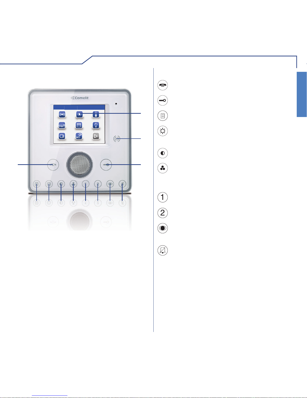
KEY FUNCTIONSMONITOR DESCRIPTION
1 Touch screen
2 Key sensor
3 Door lock key
4 Privacy / Doctor key (programmable)
5 Self-ignition key (programmable)
6 Programmable key 2
7 Programmable key 1
8 Colour key
9 Contrast key
10 Brightness key
11 Menu key
12 Audio key
Menu key: switches the Planux Manager
monitor on and off.
Audio key: activates or de-activates
conversation with the external unit.
Door lock key: opens the corresponding door
lock.
Brightness key: adjusts the brightness of the
image displayed in a video message.
Contrast key: adjusts the contrast of the image
displayed in a video message.
Colour key: adjusts the colour of the image
displayed on the monitor. To change the setting,
press the key while video communication is in
progress.
Programmable key 1: factory-set as secondary
switchboard call (programmable).
Programmable key 2: factory-set as generic
actuator (programmable).
Privacy/Doctor function key (programmable):
• The Privacy function disables calls from the
external unit and switchboard.
• The Doctor function enables automatic
activation of the lock-release in response to a
call from the external unit.
• The Privacy + Doctor function, as well as
disabling the door-entry phone ringtone in the
same way as the Privacy function, also enables
automatic activation of the lock-release in
response to a call from the external unit.
The red LED indicates that the selected
function is active.
Self-ignition key: switches on the monitor and
displays the video feed from the external unit
(programmable).
Page 6
INTRODUCTION
6
INTRODUCTION
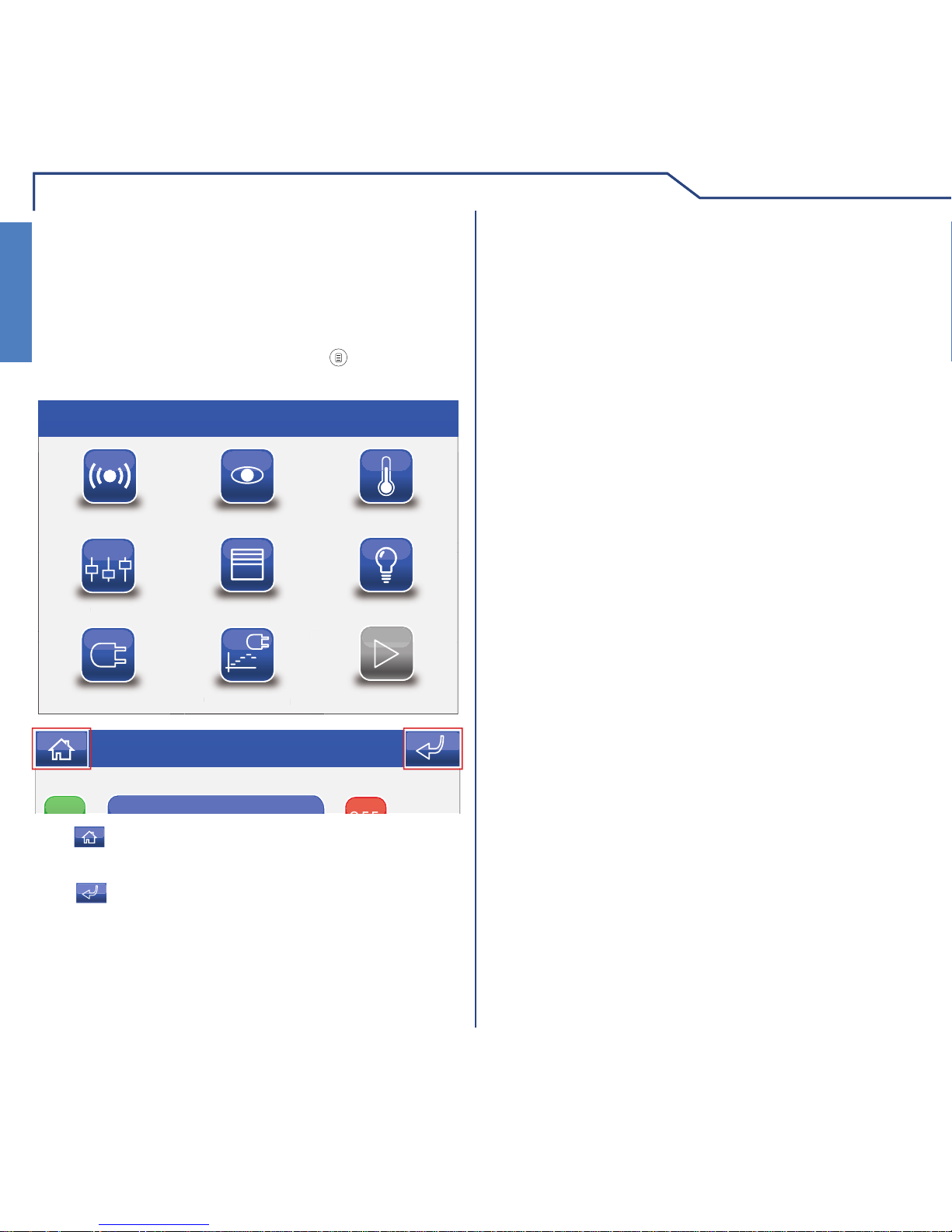
PLANUX MANAGER MENU
The Planux Manager icons change depending on the
type of system installed and the functions available.
To navigate the menu, simply use your fi nger to touch
the icon corresponding to the desired function.
To access the main menu, press the
key.
Alarm
Door entry monitors Climate
Other
Shutters Lights
Thu 21/06/12 - 16:07 0W
ther
Loads
Consumption
onsum
o
n
The icon can be used to return to the main menu
immediately.
The
icon can be used to return to the previous
screen.
Thu 21/06/12 16:07
Page 7
7
LIGHTS
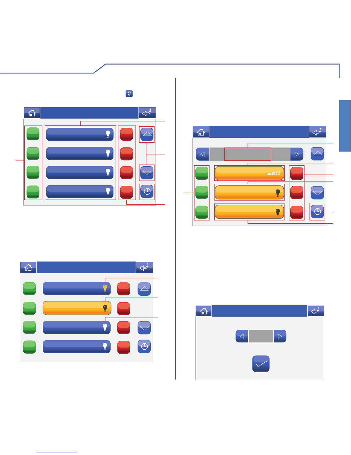
LIGHTS
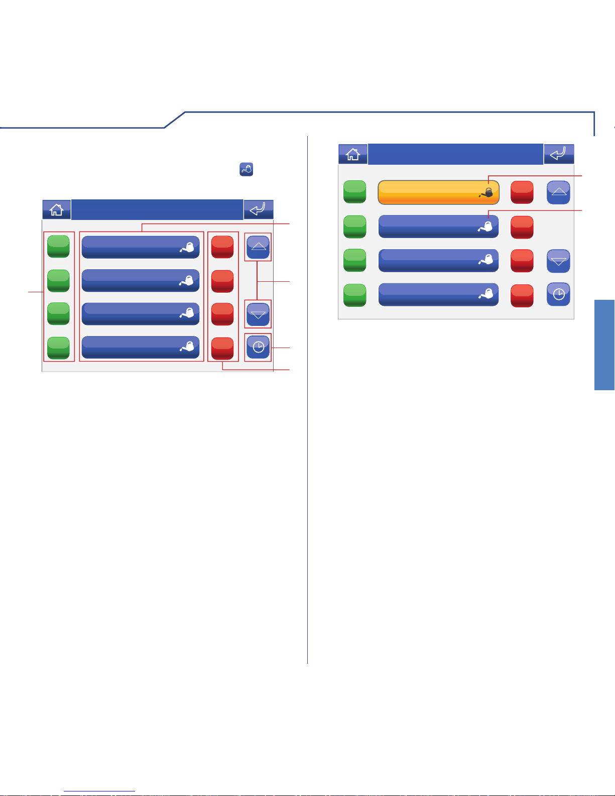
To access the lights menu, press the icon on the
main menu screen.
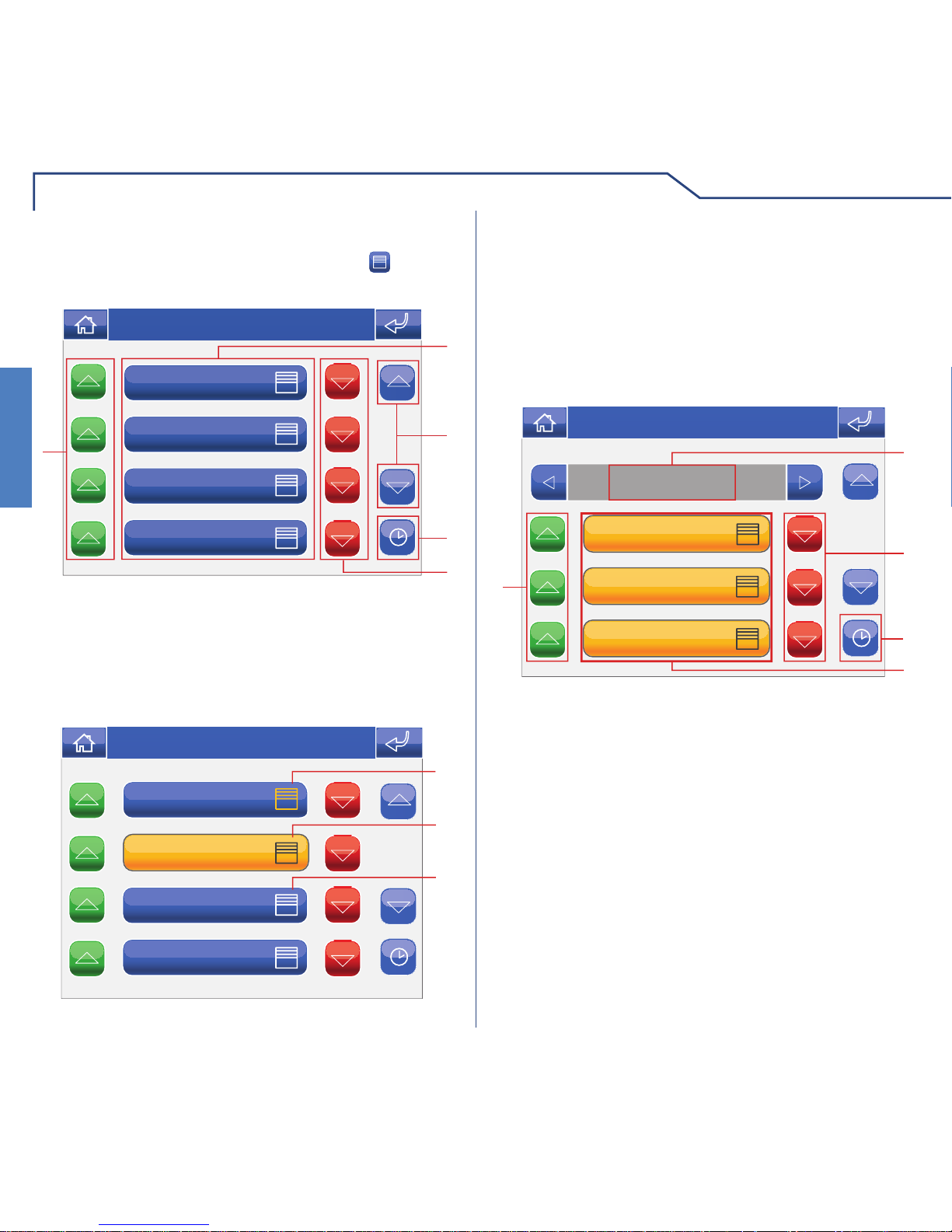
LIGHTS MENU DESCRIPTION
Attic
Downstairs area
Upstairs area
Den
ON
ON
ON
ON
OFF
OFF
OFF
OFF
1
5
4
2
3
Thu 21/06/12 - 16:07 0W
1 Available areas.
2 Scroll through the screen (only when there are
more than 4 programmed areas).
3 Light scheduling menu.
4 Switch off all lights in the corresponding area.
5 Switch on all lights in the corresponding area.
Upstairs area
Attic
Downstairs area
Den
ON
ON
ON
ON
OFF
OFF
OFF
OFF
1
2
3
Thu 21/06/12 - 16:07 0W
1 One or more lights in the area are on.
2 All lights in the area are on.
3 All lights in the area are off.
LIGHT CONTROL
The lights within various areas may be controlled
individually.
Press the relevant icon in the lights menu (e.g.
Upstairs area).
Bedroom
ON
ON
ON
OFF
OFF
OFF
Upstairs area
1
7
3
2
6
5
Thu 21/06/12 - 16:07 0W
4
Night-stand
Stairs
T
1 Area displayed.
2 Light with dimmer (press and hold to adjust the
intensity).
3 Switch light off.
4 Light ON/OFF.
5 Light scheduling menu.
6 Timed light (press to adjust the active time period),
see below.
7 Switch light on.
0:12
Thu 05/09/09 - 16:07 0W
Page 8

LIGHTS
8
LIGHTS
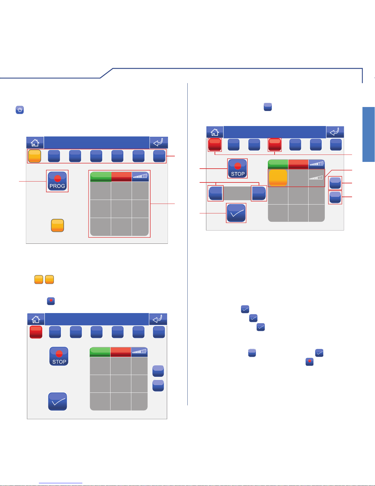
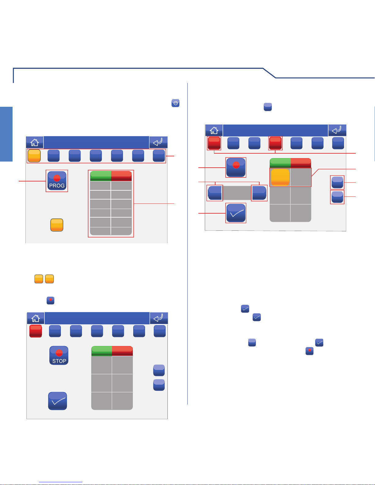
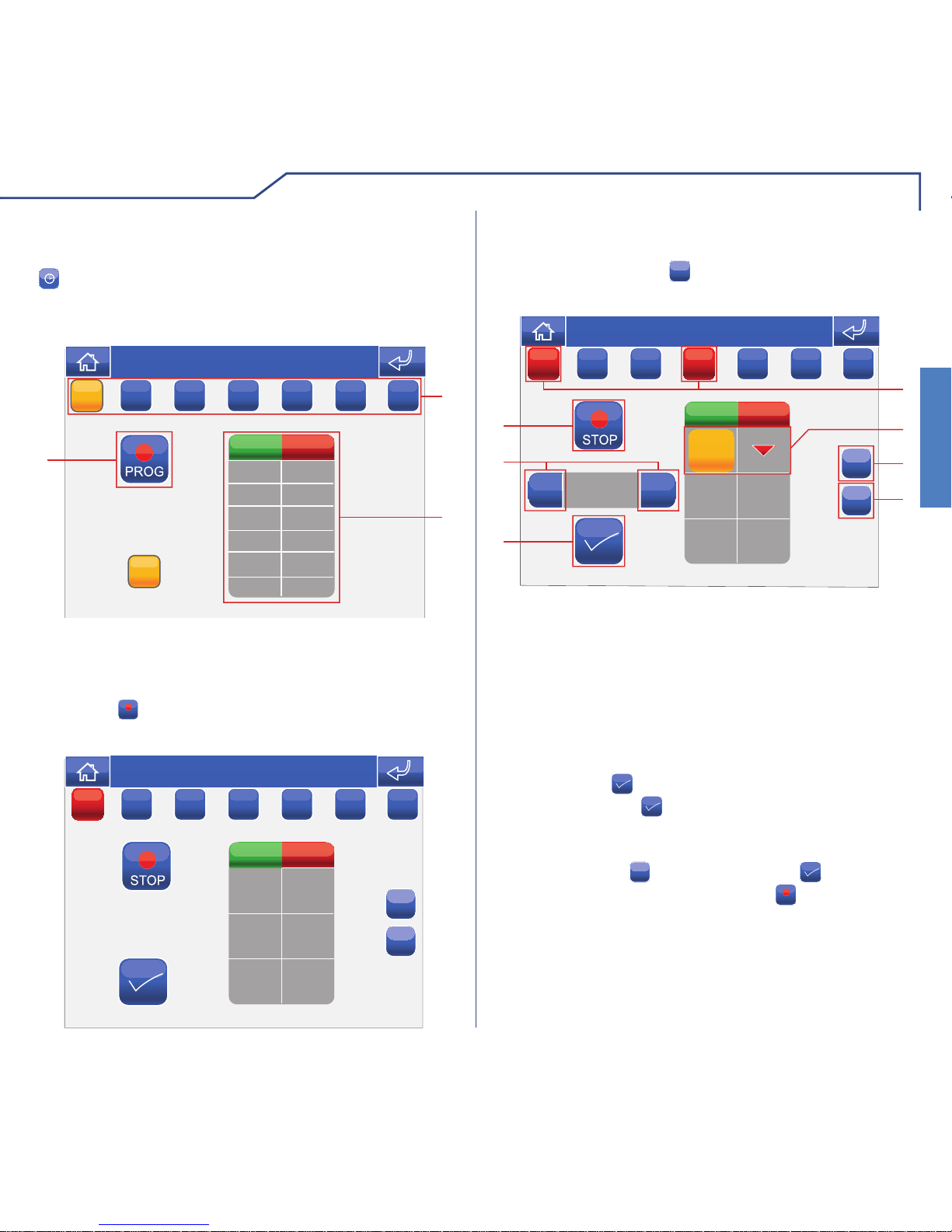
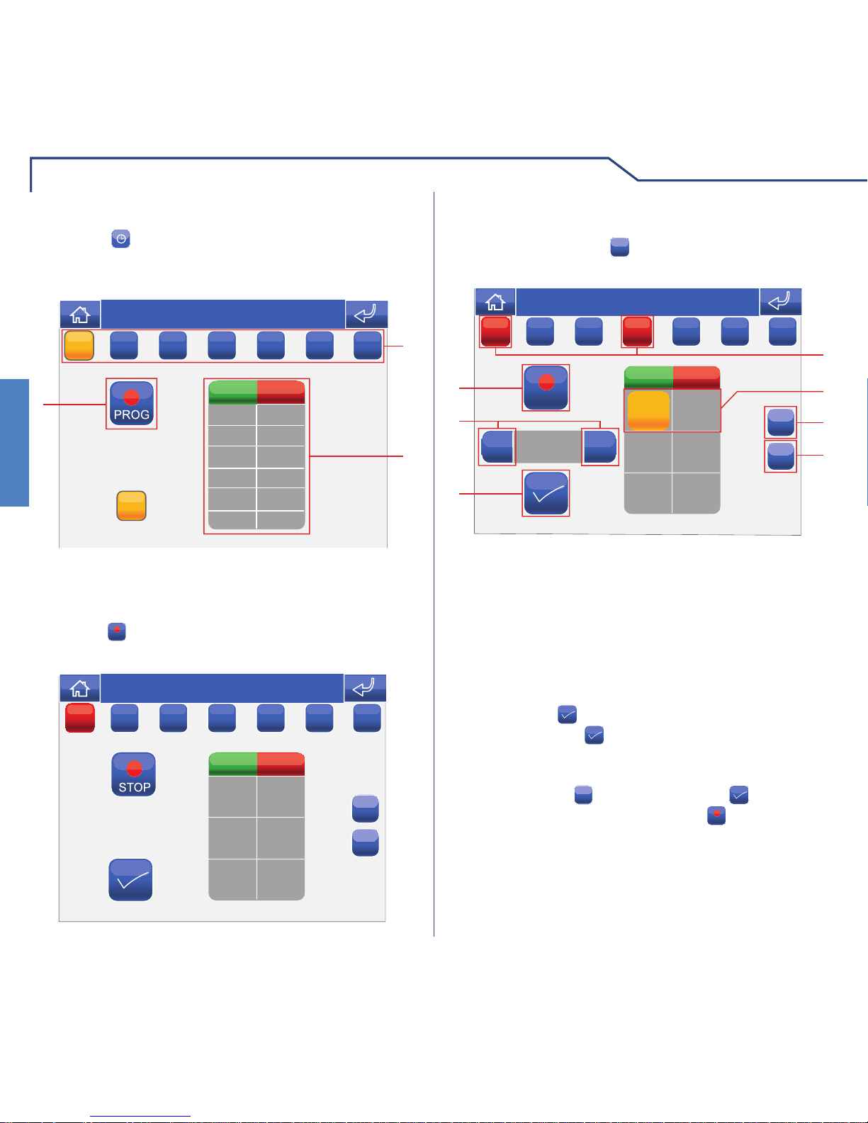
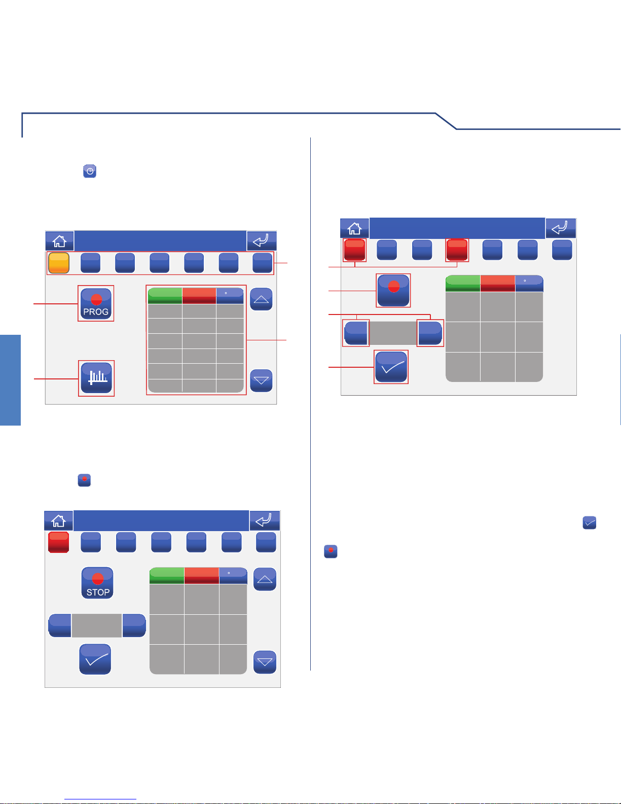
LIGHT SCHEDULING FOR AN AREA
Press the icon followed by the icon representing
one of the available areas (e.g. Downstairs area) to
access the scheduling menu for all lights in that area.
ON
1
2
3
Thu 05/09/09 - 16:07 0W
T
W
T
FSS
MM
STATUS
TIME
ONON
1 Days of the week.
2 List of logged programming.
3 Start procedure.
The
ONON/OFFOFF
icon enables/disables the current
schedule.
Press the
PROG
icon to access the programming screen.
+
x
ON
Thu 05/09/09 - 16:07 0W
STATUS
TIME
M
T
W
T
FSS
Select the days of the week for which you wish to
program the activity (selected days will be highlighted
in red) and press the
+
icon to add a programming
schedule to the list.
+
+
00:00
STOP
+
-
x
ON
00:00 OFF
4
1
36
5
7
2
Thu 05/09/09 - 16:07 0W
STATUS
TIME
MM
T
W
T
FSS
Set the desired activity time using the selector keys
and press the icon to confi rm. Select the desired
status and press
to confi rm. Repeat the above
steps as necessary to add several programming
schedules. To delete a programming schedule, select
it and press the x icon, followed by to confi rm.
When you have fi nished, press the
STOP
icon to log the
information.
1 Days of the week selected.
2 Programming saved.
3 Add programming.
4 Delete programming.
5 Confi rm.
6 Selector keys to modify time and status.
7 Save.
Page 9
9
LIGHTS
LIGHTS
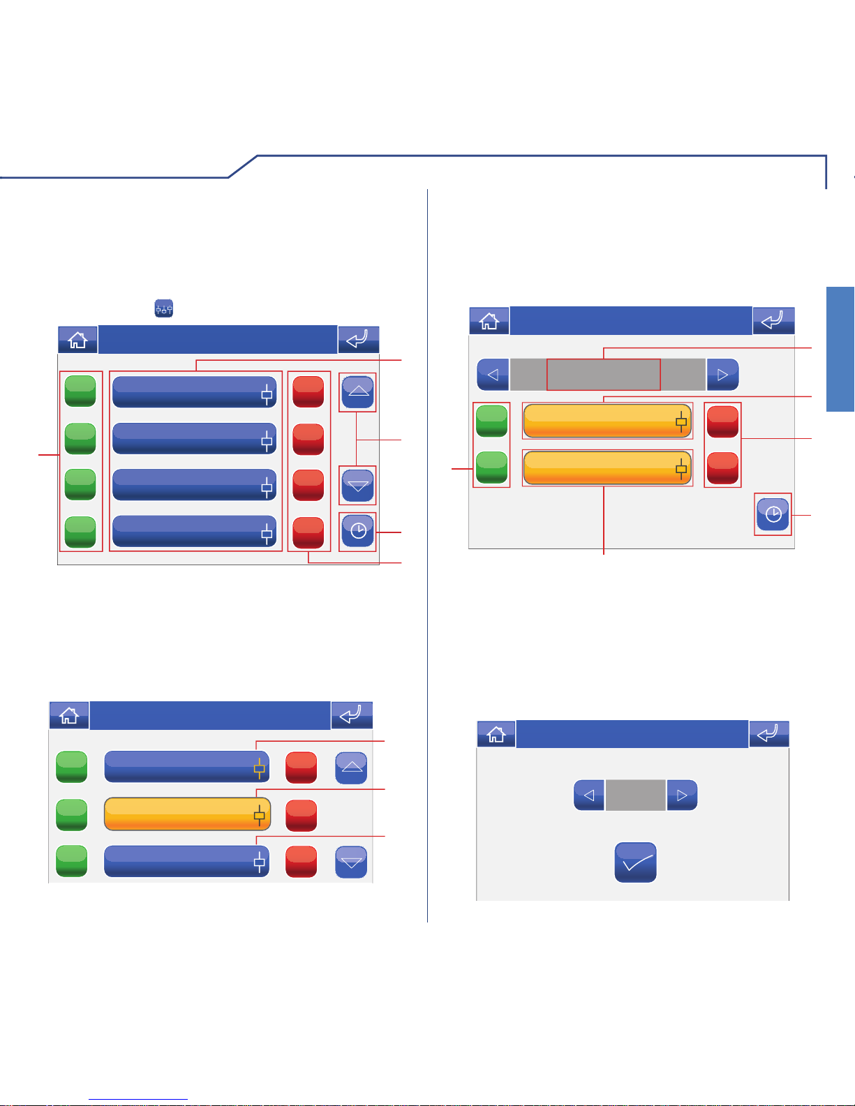
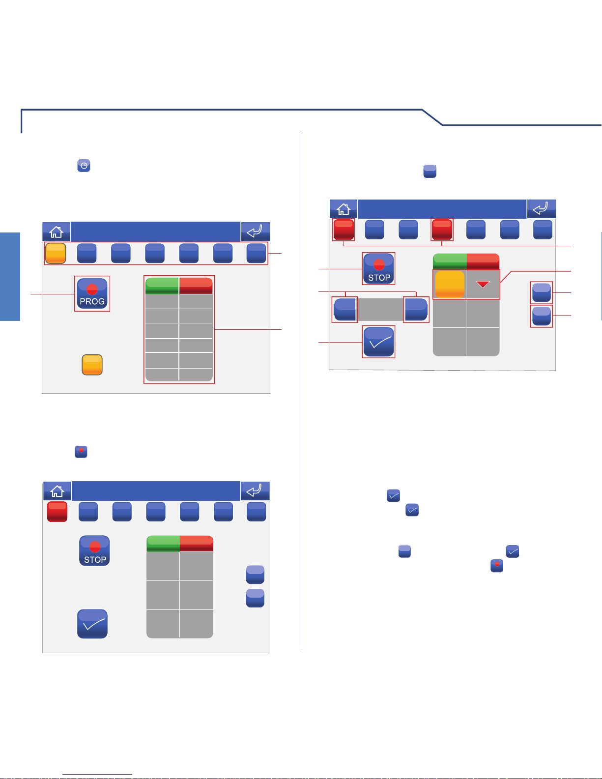
The
ONON/OFFOFF
icon enables/disables the current
schedule.
Select the days of the week for which you wish to
program the activity (selected days will be highlighted
in red) and press the
+
icon to add a programming
schedule to the list.
00:00
+
-
x
+
1
7
6
5
2
00:00 ON
4
3
Thu 05/09/09 - 16:07 0W
STATUS
TIME
M
T
W
T
FSS
1 Days of the week selected.
2 Programming saved.
3 Add programming.
4 Delete programming.
5 Confi rm.
6 Selector keys to modify time and status.
7 Save.
Set the desired activity time using the selector keys
and press the
icon to confi rm. Select the desired
status and press
to confi rm. Set the brightness of
the light and press to confi rm. Repeat the above
steps as necessary to add several programming
schedules. To delete a programming schedule, select
it and press the x icon, followed by to confi rm.
When you have fi nished, press the
STOP
icon to log the
information.
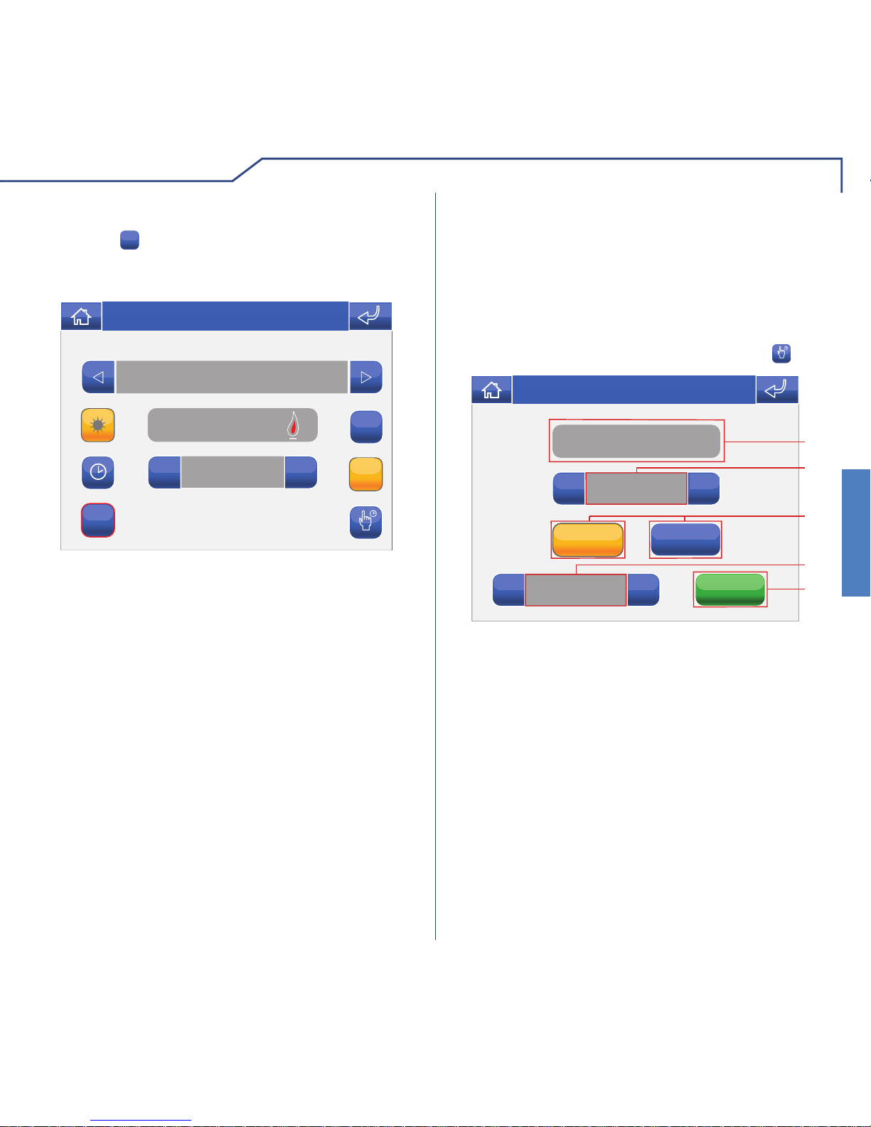
DIMMER LIGHT SCHEDULING
Once you have entered the relevant area, press the
icon and then the icon corresponding to one of the
dimmer lights available (e.g. Bedroom) to access the
dimmer light scheduling menu.
1 Days of the week.
2 List of logged programming.
3 Start programing.
ON
1
3
2
Thu 05/09/09 - 16:07 0W
MM
STATUS
TIME
T
W
T
FSS
ONON
Press the
PROG
icon to access the programming screen.
x
+
Thu 05/09/09 - 16:07 0W
STATUS
TIME
M
T
W
T
FSS
Page 10
LIGHTS
10
LIGHTS
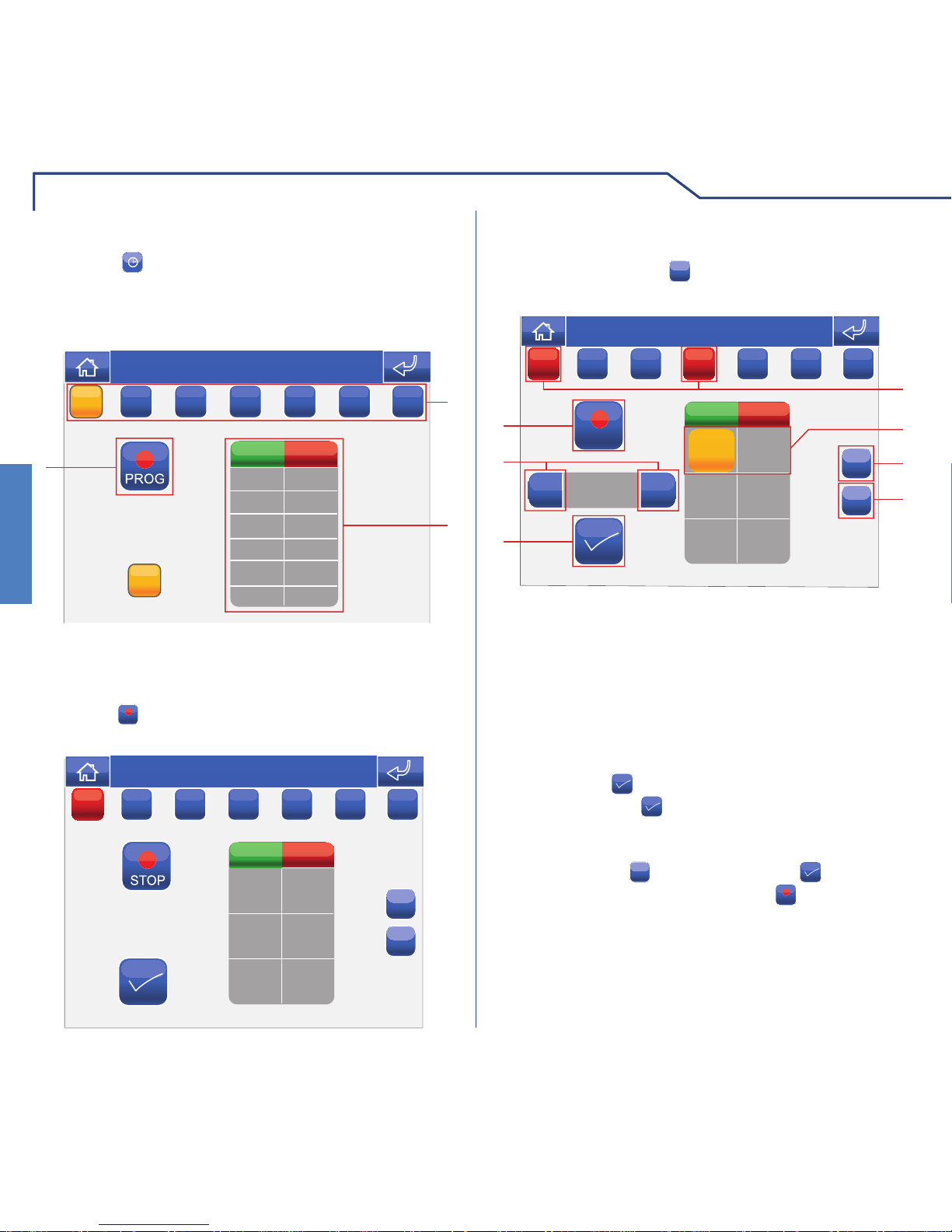
LIGHT SCHEDULING
Once you have entered the relevant area, press the
icon and then the icon corresponding to one of the lights
available (e.g. Night-stand); this will take you to the dimmer
light scheduling menu.
1 Days of the week.
2 List of logged programming.
3 Start procedure.
Press the
PROG
icon to access the programming screen.
MM
ON STATUS
TIME
1
3
2
Thu 05/09/09 - 16:07 0W
T
W
T
FSS
ONON
+
x
ON STATUS
TIME
Thu 05/09/09 - 16:07 0W
M
T
W
T
FSS
Select the days of the week for which you wish to
program the activity (selected days will be highlighted
in red) and press the + icon to add a programming
schedule to the list.
+
+
00:00
STOP
+
-
x
ON
00:00 OFF
4
1
36
5
7
2
Thu 05/09/09 - 16:07 0W
STATUS
TIME
MM
T
W
T
FSS
1 Days of the week selected.
2 Programming saved.
3 Add programming.
4 Delete programming.
5 Confi rm.
6 Selector keys to modify time and status.
7 Save.
Set the desired activity time using the selector keys
and press the
icon to confi rm. Select the desired
status and press to confi rm. Repeat the above
steps as necessary to add several programming
schedules. To delete a programming schedule, select
it and press the x icon, followed by to confi rm.
When you have fi nished, press the
STOP
icon to log the
information.
The
ONON/OFFOFF
icon enables/disables the current
schedule.
Page 11
11
OTHER
OTHER
The Other menu manages the programming and
control of loads or generic electrical commands
(connected to SimpleHome module outputs) not
included in the other menus. To access the Other
menu, press the icon on the main menu screen.
OTHER MENU DESCRIPTION
ON
ON
ON
ON
OFF
OFF
OFF
OFF
1
5
4
2
3
Thu 05/09/09 - 16:07 0W
Attic
Downstairs area
Upstairs area
Den
1 Available areas.
2 Scroll through the screen (only when there are
more than 4 programmed areas).
3 Load scheduling menu.
4 Switch off all loads in the corresponding area.
5 Switch on all loads in the corresponding area.
ON
ON
ON
OFF
OFF
OFF
1
2
3
Thu 05/09/09 - 16:07 0W
Upstairs area
Attic
Downstairs area
1 One or more loads in the area are on.
2 All loads in the area are on.
3 All loads in the area are off.
LOAD CONTROL
The loads within various areas may be controlled
individually.
Press the relevant icon in the Other menu (e.g.
Upstairs area).
TV socket
Night-stand socket
ON
ON
OFF
OFF
Upstairs area
1
6
3
2
4
Thu 21/06/12 - 16:07 0W
5
T
1 Area displayed.
2 Load ON/OFF.
3 Switch load off.
4 Load scheduling menu.
5 Timed load.
6 Load on (press to adjust the active time period),
see below.
0:12
Thu 05/09/09 - 16:07 0W
Page 12
OTHER
12
OTHER
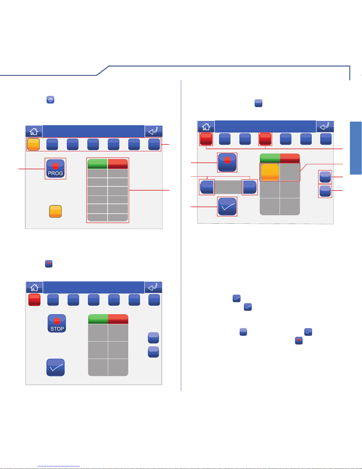
LOAD SCHEDULING
Once you have entered the relevant area, press the
icon and then the icon corresponding to one of the
loads available (e.g. Night-stand socket); this will take
you to the load scheduling menu.
1 Days of the week.
2 List of logged programming.
3 Start procedure.
Press the
PROG
icon to access the programming screen.
MM
ON STATUS
TIME
1
3
2
Thu 05/09/09 - 16:07 0W
T
W
T
FSS
ONON
+
x
ON STATUS
TIME
Thu 05/09/09 - 16:07 0W
M
T
W
T
FSS
Select the days of the week for which you wish to
program the activity (selected days will be highlighted
in red) and press the
+
icon to add a programming
schedule to the list.
+
+
00:00
STOP
+
-
x
ON
00:00 OFF
4
1
36
5
7
2
Thu 05/09/09 - 16:07 0W
STATUS
TIME
MM
T
W
T
FSS
1 Days of the week selected.
2 Programming saved.
3 Add programming.
4 Delete programming.
5 Confi rm.
6 Selector keys to modify time and status.
7 Save.
Set the desired activity time using the selector keys
and press the
icon to confi rm. Select the desired
status and press to confi rm. Repeat the above
steps as necessary to add several programming
schedules. To delete a programming schedule, select
it and press the x icon, followed by to confi rm.
When you have fi nished, press the
STOP
icon to log the
information.
Page 13
13
OTHER
OTHER
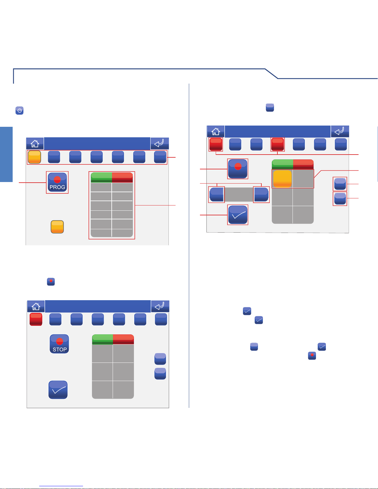
LOAD SCHEDULING FOR AN AREA
Press the icon followed by the icon representing
one of the available areas (e.g. Upstairs area) to
access the load scheduling menu for that area.
ON
1
2
3
Thu 05/09/09 - 16:07 0W
T
W
T
FSS
MM
STATUS
TIME
ONON
1 Days of the week.
2 List of logged programming.
3 Start procedure.
Press the
PROG
icon to access the programming screen.
+
x
ON
Thu 05/09/09 - 16:07 0W
STATUS
TIME
M
T
W
T
FSS
Select the days of the week for which you wish to
program the activity (selected days will be highlighted
in red) and press the
+
icon to add a programming
schedule to the list.
+
+
00:00
STOP
+
-
x
ON
00:00 OFF
4
1
36
5
7
2
Thu 05/09/09 - 16:07 0W
STATUS
TIME
MM
T
W
T
FSS
Set the desired activity time using the selector keys
and press the icon to confi rm. Select the desired
status and press
to confi rm. Repeat the above
steps as necessary to add several programming
schedules. To delete a programming schedule, select
it and press the x icon, followed by to confi rm.
When you have fi nished, press the
STOP
icon to log the
information.
1 Days of the week selected.
2 Programming saved.
3 Add programming.
4 Delete programming.
5 Confi rm.
6 Selector keys to modify time and status.
7 Save.
Page 14
14
SHUTTERS
SHUTTERS
To access the Shutters menu, press the icon on
the main menu screen.
SHUTTERS MENU DESCRIPTION
Attic
Downstairs area
Upstairs area
Den
1
5
4
2
3
Thu 05/09/09 - 16:07 0W
1 Available areas.
2 Scroll through the screen (only when there are
more than 4 programmed areas).
3 Shutter scheduling menu.
4 Close all shutters in the corresponding area.
5 Open all shutters in the corresponding area.
Upstairs area
Attic
Downstairs area
Den
1
2
3
Thu 21/06/12 - 16:07 0W
1 One or more shutters in the area are moving.
2 All shutters in the area are moving.
3 All shutters in the area are stationary.
SHUTTER CONTROL
The shutters within various areas may be controlled
individually.
Press the relevant icon in the shutters menu (e.g.
Upstairs area).
Upstairs area
1
5
2
4
3
Thu 21/06/12 - 16:07 0W
Bedroom
Night-stand
Bathroom
1 Area displayed.
2 Close shutter.
3 Shutter scheduling menu.
4 Available shutters.
5 Open shutter.
Page 15
15
SHUTTERS
SHUTTERS
SHUTTER SCHEDULING
Once you have entered the relevant area, press the
icon and then the icon corresponding to one of
the shutters available (e.g. Bedroom) to access the
shutter scheduling menu.
1 Days of the week.
2 List of logged programming.
3 Start procedure.
MM
ON STATUS
TIME
1
3
2
Thu 05/09/09 - 16:07 0W
T
W
T
FSS
ONON
Press the
PROG
icon to access the programming screen.
+
x
ON STATUS
TIME
Thu 05/09/09 - 16:07 0W
M
T
W
T
FSS
Select the days of the week for which you wish to
program the activity (selected days will be highlighted
in red) and press the
+
icon to add a programming
schedule to the list.
+
+
00:00
+
-
x
ON STATUS
TIME
00:00
4
1
36
5
7
2
Thu 05/09/09 - 16:07 0W
M
T
W
T
FSS
Set the desired activity time using the selector keys
and press the icon to confi rm. Select the desired
action and press
to confi rm. Repeat the above
steps as necessary to add several programming
schedules. To delete a programming schedule, select
it and press the x icon, followed by to confi rm.
When you have fi nished, press the
STOP
icon to log the
information.
1 Days of the week selected.
2 Programming saved.
3 Add programming.
4 Delete programming.
5 Confi rm.
6 Selector keys to modify time and status.
7 Save.
Page 16
SHUTTERS
16
SHUTTERS
SHUTTER SCHEDULING FOR AN AREA
Press the icon followed by the icon representing
one of the available areas (e.g. Upstairs area) to
access the shutter scheduling menu for that area.
ON
1
2
3
Thu 05/09/09 - 16:07 0W
T
W
T
FSS
MM
STATUS
TIME
ONON
1 Days of the week.
2 List of logged programming.
3 Start procedure.
Press the
PROG
icon to access the programming screen.
+
x
ON
Thu 05/09/09 - 16:07 0W
STATUS
TIME
M
T
W
T
FSS
Select the days of the week for which you wish to
program the activity (selected days will be highlighted
in red) and press the
+
icon to add a programming
schedule to the list.
Set the desired activity time using the selector keys
and press the
icon to confi rm. Select the desired
status and press
to confi rm. Repeat the above
steps as necessary to add several programming
schedules. To delete a programming schedule, select
it and press the x icon, followed by to confi rm.
When you have fi nished, press the
STOP
icon to log the
information.
1 Days of the week selected.
2 Programming saved.
3 Add programming.
4 Delete programming.
5 Confi rm.
6 Selector keys to modify time and status.
7 Save.
+
+
00:00
+
-
x
ON STATUS
TIME
00:00
4
1
36
5
7
2
Thu 05/09/09 - 16:07 0W
M
T
W
T
FSS
Page 17
17
AUTOMATION
AUTOMATION
To access the automation menu, press the icon on
the main menu screen.
AUTOMATION MENU DESCRIPTION
Garage door 2
Entry gate
Garage door 1
Rear gate
ON
ON
ON
ON
OFF
OFF
OFF
OFF
1
5
4
2
3
Thu 05/09/09 - 16:07 0W
1 Available automations.
2 Scroll through the screen (only when there are
more than 4 programmed automations).
3 Automation scheduling menu.
4 Stop corresponding automation.
5
Start corresponding automation.
Entry gate
Garage door 2
Garage door 1
Rear gate
ON
ON
ON
ON
OFF
OFF
OFF
OFF
1
2
Thu 21/06/12 - 16:07 0W
1 Automation in operation.
2 Automation off.
Page 18
AUTOMATION
18
AUTOMATION
AUTOMATION SCHEDULING
Press the icon followed by the icon representing
one of the available areas (e.g. entrance gate), to
access the automation scheduling menu.
1 Days of the week.
2 List of logged programming.
3 Start procedure.
MM
ON STATUS
TIME
1
3
2
Thu 05/09/09 - 16:07 0W
T
W
T
FSS
ONON
Press the
PROG
icon to access the programming screen.
+
x
ON STATUS
TIME
Thu 05/09/09 - 16:07 0W
M
T
W
T
FSS
Select the days of the week for which you wish to
program the activity (selected days will be highlighted
in red) and press the
+
icon to add a programming
schedule to the list.
Set the desired activity time using the selector keys
and press the
icon to confi rm. Select the desired
action and press
to confi rm. Repeat the above
steps as necessary to add several programming
schedules. To delete a programming schedule, select
it and press the x icon, followed by to confi rm.
When you have fi nished, press the
STOP
icon to log the
information.
1 Days of the week selected.
2 Programming saved.
3 Add programming.
4 Delete programming.
5 Confi rm.
6 Selector keys to modify time and status.
7 Save.
+
+
00:00
STOP
+
-
x
ON
00:00 OFF
4
1
36
5
7
2
Thu 05/09/09 - 16:07 0W
STATUS
TIME
MM
T
W
T
FSS
Page 19
19
IRRIGATION
IRRIGATION
To access the Irrigation menu, press the icon on
the main menu screen.
IRRIGATION MENU DESCRIPTION
East Garden
North Garden
South Garden
West Garden
ON
ON
ON
ON
OFF
OFF
OFF
OFF
1
5
4
2
3
Thu 05/09/09 - 16:07 0W
1 Available areas.
2 Scroll through the screen (only when there are
more than 4 programmed areas).
3 Irrigation scheduling menu.
4 Stop irrigation system for the relevant area.
5 Start irrigation system for the relevant area.
East Garden
South Garden
West Garden
ON
ON
ON
ON
OFF
OFF
OFF
OFF
1
2
Thu 21/06/12 - 16:07 0W
North Garden
1 Area irrigation system on.
2 Area irrigation system off.
Page 20
IRRIGATION
20
IRRIGATION
IRRIGATION SCHEDULING
MM
ON STATUS
TIME
1
3
2
Thu 05/09/09 - 16:07 0W
T
W
T
FSS
ONON
Press the icon followed by the icon representing
one of the available areas (e.g. Garden North) to
access the irrigation system scheduling menu.
1 Days of the week.
2 List of logged programming.
3 Start procedure.
Press the
PROG
icon to access the programming screen.
+
x
ON STATUS
TIME
Thu 05/09/09 - 16:07 0W
M
T
W
T
FSS
Select the days of the week for which you wish to
program the activity (selected days will be highlighted
in red) and press the
+
icon to add a programming
schedule to the list.
+
+
00:00
STOP
+
-
x
ON
00:00 OFF
4
1
36
5
7
2
Thu 05/09/09 - 16:07 0W
STATUS
TIME
MM
T
W
T
FSS
Set the desired activity time using the selector keys
and press the icon to confi rm. Select the desired
status and press
to confi rm. Repeat the above
steps as necessary to add several programming
schedules. To delete a programming schedule, select
it and press the x icon, followed by to confi rm.
When you have fi nished, press the
STOP
icon to log the
information.
1 Days of the week selected.
2 Programming saved.
3 Add programming.
4 Delete programming.
5 Confi rm.
6 Selector keys to modify time and status.
7 Save.
Page 21
21
CLIMATE
CLIMATE
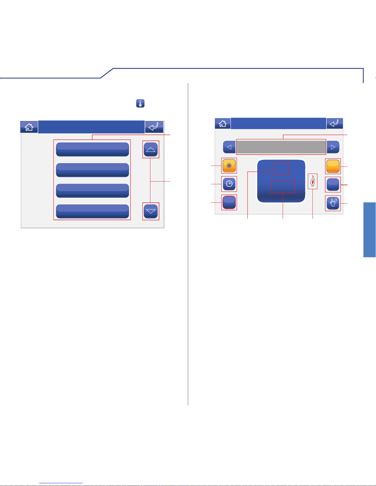
T o access the Climate menu, press the icon on the
main menu screen.
CLIMATE MENU DESCRIPTION
Bedroom 1
Bedroom 2
Lounge
Bathroom
1
2
Thu 21/06/12 - 16:07 0W
20°
23°
18°
19°
1 Available areas.
2 Scroll through the screen (only when there are
more than 4 programmed areas).
Bedroom 1
ON
M
AA
1
10
2
3
9
4
8
Thu 21/06/12 - 16:07 0W
20°
+
-
22.5°
7
65
CLIMATE CONTROL
Press the relevant icon in the climate menu (e.g.
Bedroom 1).
1 Area displayed.
2 Automatic mode.
3 Manual mode.
4 Manual forcing.
5 Boiler on indicator.
6 Current set temperature.
7 Room temperature.
8 System activation / deactivation (the timer-
thermostat switches off / on).
9 Climate scheduling menu.
10 Summer / winter mode selection (heating / cooling
management).
Page 22
CLIMATE
22
CLIMATE
CLIMATE SCHEDULING
FROM TO T
MM
1
4
2
3
Thu 05/09/09 - 16:07 0W
T
W
T
FSS
Press the icon to access the scheduling menu
for the climate control system in the relevant area.
Function only available on monitors set as Master
devices.
1 Days of the week.
2 List of logged programming.
3 Daily programming graphic.
4 Start procedure.
Press the
PROG
icon to access the programming screen.
NOTE: daily climate control programming must
refer to the whole 24-hour cycle; any hours not
programmed by the user will be set by the system
automatically.
00:00
FROM TO T
18.5°
00:00 24:00
+
-
Thu 05/09/09 - 16:07 0W
M
T
W
T
FSS
Select the days of the week for which you wish to
program the activity (selected days will be highlighted
in red), select the time or temperature to be adjusted
and press + and – to increase or decrease the value.
Every time you adjust a value, you must press the
icon to confi rm. When you have fi nished, press the
STOP
icon to log the information.
00:00
FROM TO T
18.5°
00:00 24:00
STOP
+
-
1
2
3
4
Thu 05/09/09 - 16:07 0W
M
T
W
T
FSS
1 Days of the week selected.
2 Save.
3 Selector keys to modify time and temperature.
4 Confi rm.
Page 23
23
CLIMATE
CLIMATE
MANUAL CLIMATE MODE
Press the M icon to set the climate to manual
mode and use the + and – selectors to adjust the
temperature of the room.
Bedroom 1
20°
22.5°
+
-
ON
MM
A
Thu 05/09/09 - 16:07 0W
CLIMATE FORCING
If necessary , it is possible to force both automatic and
manual programming for a set period of time (hours
or days).
Once the forcing cycle has fi nished the system will
revert to the mode set previously (Automatic or
Manual).
In the menu for the relevant area, press the
icon.
20°
22.5°
+
-
03:50
+
-
DAYS
START
HOURS
1
2
3
4
5
Thu 05/09/09 - 16:07 0W
1 Current temperature.
2 Desired temperature.
3 Hours / days selectors.
4 Desired running time.
5 Start forcing mode.
Page 24
LOADS
24
LOADS
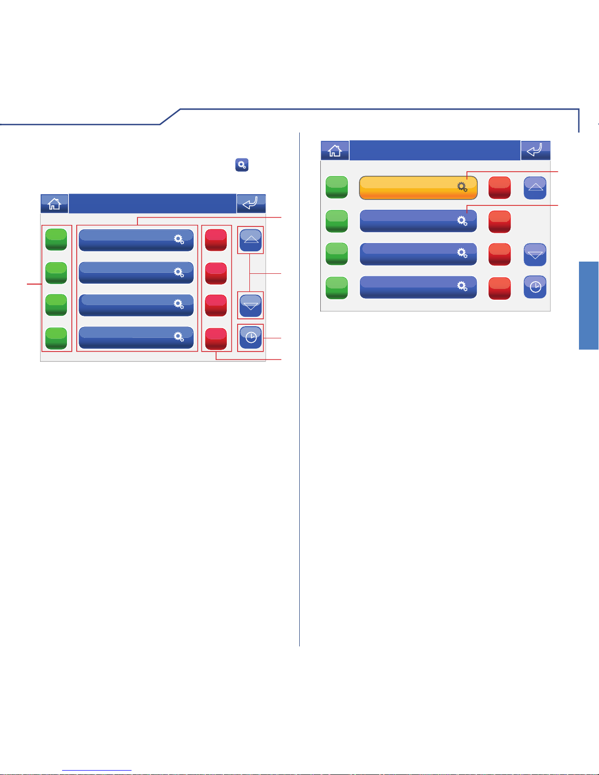
LOADS MENU DESCRIPTION
Refrigerator
Thu 21/06/12 - 16:07 0W
1
2
Dishwasher
Washing machine
Oven
1 Loads selected for deactivation in the event of an
overload.
2 Load to remain active.
To access the Loads menu, press the
icon on the
main menu screen.
In the event of an overload, the system automatically
decides which of the active programmed loads to
disable.
The user, via the loads menu, will be able to:
1 Select the loads to be disabled in the event of an
overload.
2 Deselect the loads to be left enabled in the event
of an overload.
Page 25

25
CONSUMPTION
CONSUMPTION
To access the Consumption menu, press the icon
on the main menu screen.
CONSUMPTION MENU DESCRIPTION
Electricity
Wed 31/07/13 - 08:31
G
Wh
02461218
170.0
154.0
138.0
122.0
106.0
90.00
133 Wh
31.04 kWh
1
2
3
4
5
6
1 Change currency / unit of measurement mode.
2 Meter currently displayed.
3 Scroll through available meters.
4 Change day / month / year / log mode.
5 Scroll through days / months / years / log.
6 Change graph / table display.
This menu can be used for monitoring consumption
though graphs and tables.
KEY TO THRESHOLD COLOURS
If the maximum consumption thresholds are set (see
Thresholds menu on page 37) in table mode, the
check boxes are coloured to indicate the consumption
level.
00.00
01.00
02.00
03.00
04.00
05.00
117
100
134
108
164
121
From 0% to 75%
From 75% to 100%
Over 100%
Page 26

26
DOOR ENTRY MONITORS
DOOR ENTRY MONITORS
Video memory
ON
OFF
Hands-free
Set melodies
Volume adjustment
ON
OFF
1
2
4
3
Thu 21/06/12 - 16:07 0W
Actuators
Cameras
1
3
Thu 21/06/12 - 16:07 0W
Intercoms
Main switchboard
3
C
1
2
3
Thu 05/09/09 - 16:07 0W
11/01/2001 10:21 09/01/2001 8:22
07/01/2001 18:50
05/01/2001 9:48
To access the Door entry monitors menu, press the
icon on the main menu screen.
DOOR ENTRY MONITORS MENU DESCRIPTION
The LEDs corresponding to the audio and door lock
keys fl ash on receipt of a call.
Press the
key to activate the audio line with the
external unit from which the call originated.
Press
to activate the corresponding door lock.
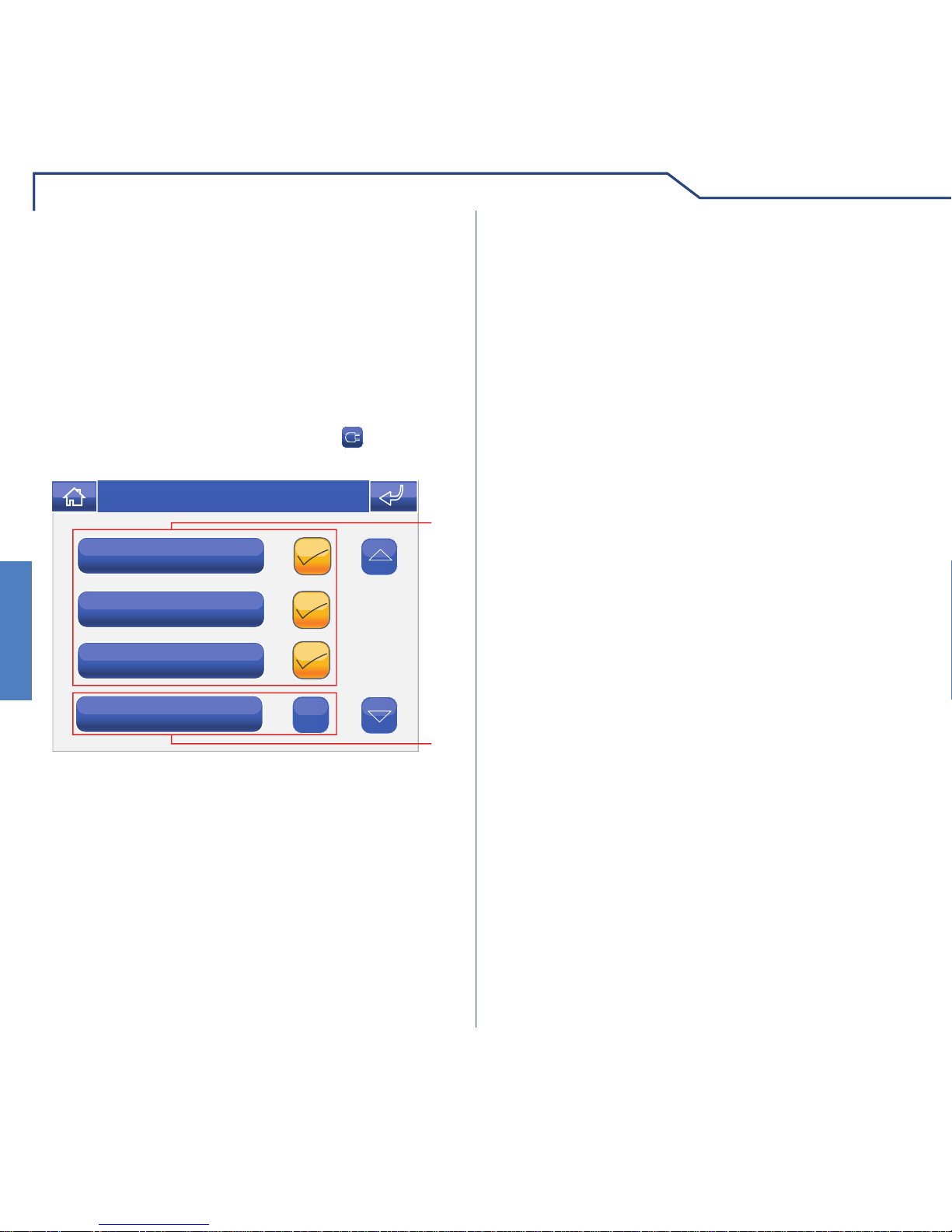
ANSWERING A CALL
1 Functions available in the Door entry monitors menu.
2 Deactivation of the corresponding function.
3 Scroll through the screen.
4 Activation of the corresponding function.
The Video memory function, if activated, can be used
to record the image from the external unit camera
when a call is made, for a maximum of 100 recordings
of max. 10 seconds each.
VIDEO MEMORY
To view the list of recordings present, access the
Door entry monitors > Video memory menu.
1 Recordings not yet viewed (blue frame).
2 Recordings already viewed (yellow frame).
3 Delete recording.
Recordings are saved in .avi format on the SD card,
in the "Video" folder , and may also be viewed on a PC
using Windows Media Player. If there is no SD card,
the recordings will be saved in the Planux Manager
device memory (MAX. 2 recordings).
Page 27

27
DOOR ENTRY MONITORS
DOOR ENTRY MONITORS
confirm deletion of
video message?
YES NO
Thu 21/06/12 - 16:07 0W
External call
Switchboard call
Floor door call
Multi add. call
Melody 3
Melody 1
Melody 2
Melody 4
Thu 05/09/09 - 16:07 0W
T o view one of the recordings, press the corresponding
icon.
VIEWING A RECORDING
When it has fi nished replaying (MAX. 10 seconds),
the system will automatically return to the previous
screen.
To delete one of the recordings, press the
C
icon
followed by the icon corresponding to the recording
you wish to delete, then confi rm.
DELETING A RECORDING
The Hands-free function activates the audio line in
response to a call, without having to press the
key .
HANDS-FREE
To manage the Planux Manager melodies, access
the Door entry monitors > Set melody menu.
SETTING MELODIES
Select the type of call for which you wish to modify the
melody by pressing the relevant icon.
To listen to the melody, press the desired name,
followed by the icon to the right of it if you wish to
save the setting.
Customised ringtones may be added. Files must be 8 Khz
mono 16 bit, in .wav format. Place the melodies in the “Wav”
folder on the SD card to display them in the relevant menu.
Page 28

DOOR ENTRY MONITORS
28
DOOR ENTRY MONITORS
Actuator 1
Actuator 2
Actuator 3
Actuator 4
ABC
1
2
Thu 05/09/09 - 16:07 0W
Ringtone
Audio
Intercom audio
Keys
Thu 21/06/12 - 16:07 0W
Ringtone
Audio
B
B
+
-
Thu 05/09/09 - 16:07 0W
Generic Actuator
Actuator command sent
Thu 05/09/09 - 16:07 0W
ADJUSTING THE VOLUME
To adjust the ringtone, audio, key tone or alarm tone
volume, access the Door entry monitors > Volume
adjustment menu.
Select the function for which you intend to adjust the
volume by pressing the corresponding icon. When
the adjustment screen appears, use the + and – icons
to adjust the volume and press the
icon to confi rm.
ACTUATORS
To view the list of actuators present, access the menu
Door entry monitors > Actuators.
1 Actuators available. Other devices may be added
by the installer.
2 Rename actuators.
To control an actuator which is already on the list,
simply press the corresponding icon.
If no actuator is connected, the message “DEVICE
NOT PRESENT” will appear on the display.
Page 29

29
DOOR ENTRY MONITORS
DOOR ENTRY MONITORS
Name
Thu 05/09/09 - 16:07 0W
Camera 1
Camera 2
Camera 3
Camera 4
ABC
1
2
Thu 05/09/09 - 16:07 0W
Generic Actuator
Device not present
Thu 05/09/09 - 16:07 0W
RENAMING ACTUA T ORS
Press the
ABC
icon followed by the icon corresponding
to the actuator you wish to rename.
Enter the desired actuator name and/or number and
press the
icon to confi rm.
Press the
123
icon to switch to the numerical keypad.
CAMERAS
To view the list of cameras present, access the menu
Door entry monitors > Cameras.
1 Cameras available. Each icon may be associated
with up to 3 cameras which can be viewed in
sequence, in addition to the camera monitoring the
external unit.
2 Rename cameras.
To display the image from one of the cameras on the
list, simply press the corresponding icon.
Page 30

DOOR ENTRY MONITORS
30
DOOR ENTRY MONITORS
Generic Actuator
Device not present
Thu 05/09/09 - 16:07 0W
Name
Thu 05/09/09 - 16:07 0W
If no camera is connected, the message “DEVICE
NOT PRESENT” will appear on the display.
When a video image is displayed, to return to the
menu simply touch the screen; to view other camera
images press an icon again.
RENAMING CAMERAS
Press the
ABC
icon followed by the icon corresponding
to the group of cameras you wish to rename.
Enter the desired camera name and/or number and
press the
icon to confi rm.
Press the
123
icon to switch to the numerical keypad.
Page 31

31
DOOR ENTRY MONITORS
DOOR ENTRY MONITORS
Intercom 1
Intercom 2
Intercom 3
Intercom 4
ABC
1
2
Thu 05/09/09 - 16:07 0W
Generic Actuator
Intercom executed
Thu 05/09/09 - 16:07 0W
INTERCOMS
To view the list of intercom calls present, access the
Door entry monitors > Intercoms menu.
1 Intercom calls available.
2 Rename intercom call.
To make an intercom call, simply press the icon.
Name
Thu 05/09/09 - 16:07 0W
RENAMING INTERCOMS
Press the
ABC
icon followed by the icon corresponding
to the intercom call you wish to rename.
Enter the desired intercom name and/or number and
press the
icon to confi rm.
Press the
123
icon to switch to the numerical keypad.
Page 32

32
SETUP
SETUP
Rain
English
Français
Deutsch
Italiano
1
3
2
Thu 05/09/09 - 16:07 0W
1 Language in use.
2 Scroll through the screen.
3 Languages available.
To access the Setup menu, press the
icon on the
main menu screen.
SETUP MENU DESCRIPTION
Information
Set date and time
Lock keypad and touch-screen
Language
2
1
Thu 21/06/12 - 16:07 0W
Consumption
Conditions
Advanced
1
2
Thu 21/06/12 - 16:07 0W
1 Functions available in the Setup menu.
2 Scroll through the screen.
The Planux Manager menu display language can be
changed by selecting one of the options on the list.
Access the menu Setup > Language.
LANGUAGE
To select the language, press the corresponding icon.
The Lock keypad and touch-screen function
temporarily deactivates the Planux Manager keys
and touch-screen. The functions are reactivated after
60 seconds, or on receipt of a call.
To activate the function, press the “Lock keypad and
touch-screen” icon.
LOCKING THE KEYP AD AND TOUCH-SCREEN
Information
Set date and time
Language
Lock keypad and touch-screen
Confirm lock keypad and
touch-screen for 60 seconds?
YES
NO
Thu 05/09/09 - 16:07 0W
Page 33

33
SETUP
SETUP
To set the date and time, access the menu Setup >
Set date and time.
Use the + and – icons to set the various fi elds. When
you have fi nished, press the icon to confi rm.
SETTING THE DATE & TIME
05
+
-
16:07
+
-
05
+
-
09
+
-
2
3
1
4
Thu 05/09/09 - 16:07 0W
1 Day.
2 Month.
3 Year.
4 Time.
To view the software version installed, access the
Information menu.
INFORMATION
Adjust volumes
Set melodies
Prog. keys
Information
B
VERS. SW: 1.5
VERS. EE: 1.3.2 6214C
SB CODE: 5P RANGE: 0 - 0
Intercom add. : 5
SLAVE
Thu 21/06/12 - 16:07 0W
Confi rm by pressing the
YES
icon.
Information
Set date and time
Language
Keypad locked
Thu 05/09/09 - 16:07 0W
CONDITIONS
This menu is only available if the system has
conditioned outputs and if the monitor is set as a
Master.
Conditioned output 3
Conditioned output 1
Conditioned output 2
Conditioned output 4
ON
ON
ON
ON
OFF
OFF
OFF
OFF
1
4
2
3
Thu 21/06/12 - 16:07 0W
1 Available outputs.
2 Scroll through the screen.
3 Deactivate corresponding output.
4 Activate corresponding output.
Page 34

SETUP-CONSUMPTION
34
SETUP - CONSUMPTION
CONSUMPTION SETUP MENU DESCRIPTION
Rates
Display
Currency
Toolbar
2
1
Thu 08/09/13 - 08:07 0W
Settings
Reset
Thresholds
Rates
1
2
Thu 08/09/13 - 08:07 0W
1 Functions available in the Consumption menu.
2 Scroll through the screen.
TOOLBAR
The Toolbar menu can be used to select which meter
to monitor on the main bar.
Water
Gas
Production
Elect. consumption
Thu 08/09/13 - 08:07 0W
Page 35

SETUP - CONSUMPTION
SETUP-CONSUMPTION
35
CURRENCY
The Currency menu can be used to select the currency
to be associated with consumption monitoring.
R
Fr
$
€
Thu 08/09/13 - 08:07 0W
Customised
£
Thu 08/09/13 - 08:07 0W
In addition to the 5 pre-set currencies you can create
a customised option by clicking the “Customised”
icon.
DISPLAY
The Display menu can be used to select the meters
connected to the system that you wish to view in the
consumption menu area.
Meter 1
Electricity 3
Electricity 2
Electricity 1
Wed 31/07/13 - 08:31
ABC
Meter 3
Meter 2
Meter 1
Wed 31/07/13 - 08:31
ABC
Page 36

SETUP - CONSUMPTION
SETUP-CONSUMPTION
36
RATES
The Rates menu can be used to set the meter rates
according to time bands. The information will then
be used to construct the consumption graphs in the
Consumption menu.
1. Select the meter for which you wish to set the
rates, for example “Electricity consumption”.
Meter
Electricity consumption
Wed 31/07/13 - 08:31
$/kwhFROM TO
PROG
1
3
2
Thu 08/09/13 - 08:07 0W
ONON
MM
T
W
T
FSS
1 Days of the week.
2 List of logged programming.
3 Start programming.
Press the
PROG
icon to access the programming screen.
NOTE: daily rate programming must refer to the
whole 24-hour cycle; any hours not programmed
by the user will be set by the system automatically .
00:00
FROM TO
0.06
00:00 24:00
STOP
+
-
1
2
3
4
$/kwh
Thu 08/09/13 - 08:07 0W
MM
T
W
T
FSS
Select the days of the week for which you wish to
program the rate (selected days will be highlighted in
red), select the time or rate to be adjusted and press
+ and – to increase or decrease the value. Every time
you adjust a value, you must press the icon to
confi rm. When you have fi nished, press the
STOP
icon
to log the information.
1 Days of the week selected.
2 Save.
3 Selector keys to modify time and rate.
4 Confi rm.
Page 37

SETUP - CONSUMPTION
SETUP-CONSUMPTION
37
THRESHOLDS
This menu can be used to set maximum thresholds
for hours, days, months and years, so that the
check boxes for the energy consumption table are
coloured to indicate the consumption level (see Key
to threshold colours on page 25), providing a report in
the event that the maximum thresholds are exceeded.
1
2 3 4
5
6 7 8
9
0 . C
Electricity
kWh
Time
Day
Month
Year
Wed 31/07/13 - 08:31
1. Select the fi eld for which you wish to set the
maximum threshold, for example “Day”.
1
2 3 4
5
6 7 8
9
0 . C
Electricity
kWh
Time
Day
Month
Year
Wed 31/07/13 - 08:31
2. Enter the value using the number keys.
3. Press the
icon to confi rm.
CLEAR
Press Clear and confi rm to reset all the meters.
Settings
Reset
Thresholds
Tariffe
Reset count
on all meters?
YES
NO
Thu 08/09/13 - 08:07 0W
Page 38

SETUP - CONSUMPTION
SETUP-CONSUMPTION
38
SETTINGS
This menu can be used to customise the settings of
the meters connected to the system.
Meter 3
Meter 2
Meter 1
Thu 08/09/13 - 08:07 0W
Select one of the meters to open the corresponding
settings menu.
Step
Pulses
Unit of meas.
Scale factor
Thu 08/09/13 - 08:07 0W
UNIT OF MEASUREMENT
In this menu you can select the unit of measurement
to be associated with the meter, in accordance with
its function (e.g. m3, l, etc.). You may use up to 3
characters.
mc
A
B C D E
F G H
I
J K L M
N O P
Q
R S T U
V W X
Y
Z
C
123
Thu 21/06/12 - 16:07 0W
Once you have entered the desired unit of
measurement, press the icon to confi rm and exit.
PULSES
The value entered in this menu determines how many
pulses need to occur before the count increases by
one step.
2
1
2 3 4 5
6 7 8
9
0
C
Thu 21/06/12 - 16:07 0W
Page 39

SETUP - CONSUMPTION
SETUP-CONSUMPTION
39
STEP
The value entered via this menu determines by how
much the count is increased following the number of
pulses set previously.
1
1
2 3 4 5
6 7 8
9
0
C
Thu 21/06/12 - 16:07 0W
SCALE FACTOR
This menu an be used to change the scale value for
the meter readings. For example, if you want to view
the values in a unit of measurement which is different
to the unit set for the meter.
1.000000
1
2 3 4 5
6 7 8
9
0
C
Thu 21/06/12 - 16:07 0W
Page 40

40
ADVANCED
ADVANCED
Access the menu Setup > Advanced.
ACCESSING ADV ANCED MENUS
ENTER PASSWORD
Thu 05/09/09 - 16:07 0W
Enter the installer password (set by default to 1961).
ADVANCED MENUS DESCRIPTION
Prog. Keys
Conf. video memory
Actuators
Cameras
2
1
Thu 21/06/12 - 16:07 0W
Intercoms
Selective intercom
Addresses
Calibrate touch-screen
2
1
Thu 21/06/12 - 16:07 0W
1 Functions available in the Advanced menu.
2 Scroll through the screen.
Set input
Total reset
2
1
Thu 21/06/12 - 16:07 0W
Page 41

41
ADVANCED
ADVANCED
KEY PROGRAMMING
To program the Planux Manager keys, access the
menu Setup > Advanced > Prog. keys menu.
Key 1
Key 2
Key
Key
1
Thu 05/09/09 - 16:07 0W
1 Programmable keys.
Select the key you want to program (e.g. Key 1).
Intercoms
Actuators
Cameras
Thu 21/06/12 - 16:07 0W
Main switchboard
Generic act.
Actuator 1
Actuator 2
Thu 05/09/09 - 16:07 0W
Actuator 3
Press the icon corresponding to the desired function
to access the submenu and view the available
modules.
In the case of the key, the available functions are:
Privacy + doctor
Doctor
Privacy
Thu 05/09/09 - 16:07 0W
Select the desired function by pressing the icon to
the right of it.
If the fl ag is removed from all functions during
programming, the key will be disabled.
Page 42

ADVANCED
42
ADVANCED
To manage the actuators, access the menu Setup >
Advanced > Actuators.
ACTUATORS
Generic act.
Actuator 1
Actuator 2
ABC
C
+
5
1
3
2
4
Thu 05/09/09 - 16:07 0W
Actuator 3
1 Actuators available.
2 Add actuator.
3 Delete actuator.
4 Modify actuator code.
5 Rename actuator (see page 29).
To add an actuator, press the
+
icon.
ADDING ACTUA T ORS
Name
Thu 05/09/09 - 16:07 0W
Enter the desired name and press the icon to
confi rm.
Enter the actuator code and press the
icon to
confi rm.
Number
C
Thu 05/09/09 - 16:07 0W
For further information regarding Art. 1256, please
refer to the Technical manual code 2G40000687.
VIDEO MEMORY SETUP
The video memory function can be set up so that all
video entry phone calls are recorded.
Thu 21/06/12 - 16:07 0W
Always record
Recording duration
ON
OFF
3
2
1
Access the menu Setup > Advanced > V ideo memory
setup.
1 Activate "Always Record" mode.
2 Deactivate "Always Record" mode.
3 Adjust the recording duration (5 or 10 seconds).
Page 43

43
ADVANCED
ADVANCED
MODIFYING AN ACTUA T OR CODE
To modify the code of an actuator, press the icon
followed by the actuator icon.
Thu 05/09/09 - 16:07 0W
Enter the desired code using the numerical keypad
and press the icon to save the information.
To delete an actuator, press the
C
icon followed by
the actuator icon.
DELETING ACTUA T ORS
Generic act.
Actuator 1
Actuator 2
ABC
C
+
Thu 05/09/09 - 16:07 0W
Actuator 3
Confi rm by pressing the
YES
icon.
Actuator 1
Actuator 2
Actuator 3
ABC
C
+
Confirm removal of actuator?
YES
NO
Thu 05/09/09 - 16:07 0W
Page 44

ADVANCED
44
ADVANCED
To manage the cameras, access the menu Setup >
Advanced > Cameras.
CAMERAS
Camera 1
Camera 2
Camera 3
Camera 4
1
ABC
C
+
5
3
2
4
Thu 05/09/09 - 16:07 0W
1 Cameras available.
2 Add camera.
3 Delete camera.
4 Modify camera code.
5 Rename camera (see page 30).
To add a camera, press the
+
icon.
ADDING CAMERAS
Name
Thu 05/09/09 - 16:07 0W
Enter the desired name and press the icon to
confi rm.
Enter the camera code and press the
icon to
confi rm.
Number
C
Thu 05/09/09 - 16:07 0W
For further information regarding Art. 1259C (remote
camera module), please refer to the Technical manual
code 2G40000690.
Page 45

45
ADVANCED
ADVANCED
Press the C icon followed by the camera icon.
DELETING CAMERAS
Confi rm by pressing the
YES
icon.
MODIFYING A CAMERA CODE
Press the icon followed by the camera icon.
Thu 05/09/09 - 16:07 0W
Enter the desired code using the numerical keypad
and press the icon to save the information.
Camera 1
Camera 2
Camera 3
Camera 4
ABC
C
+
Thu 05/09/09 - 16:07 0W
Camera 1
Camera 2
Camera 3
Camera 4
ABC
C
+
YES
NO
Confirm removal of camera?
Thu 05/09/09 - 16:07 0W
Page 46

ADVANCED
46
ADVANCED
To manage the intercoms, access the Setup >
Advanced > Intercoms menu.
INTERCOMS
Intercom 1
Intercom 2
1
ABC
C
+
5
3
2
4
Thu 05/09/09 - 16:07 0W
1 Intercom calls available.
2 Add intercom call.
3 Delete intercom call.
4 Modify intercom address.
5 Rename intercom call (see page 31).
To add an intercom call, press the
+
icon.
ADDING AN INTERCOM
Name
Thu 05/09/09 - 16:07 0W
Enter the desired name and press the icon to
confi rm.
Enter the address of the internal unit to be associated
with the call and press the
icon to confi rm.
Number
C
Thu 05/09/09 - 16:07 0W
Page 47

47
ADVANCED
ADVANCED
MODIFYING AN INTERCOM ADDRESS
Press the icon followed by the intercom call icon.
Thu 05/09/09 - 16:07 0W
Enter the desired address using the numerical
keypad and press the icon to save the information.
Press the
C
icon followed by the intercom call icon.
DELETING AN INTERCOM
Confi rm by pressing the
YES
icon.
Intercom 1
Intercom 2
ABC
C
+
Thu 05/09/09 - 16:07 0W
Intercom 1
Intercom 2
ABC
C
+
Thu 05/09/09 - 16:07 0W
YES
NO
Confirm removal of intercom?
Page 48

ADVANCED
48
ADVANCED
To manage selective intercom calls, access the menu
Setup > Advanced > Selective intercom.
SELECTIVE INTERCOM
Selective intercom 1
Selective intercom 2
1
ABC
C
+
5
3
2
4
Thu 21/06/12 - 16:07 0W
Enter the desired name and press the icon to
confi rm.
1 Selective intercom calls available.
2 Add selective intercom.
3 Delete selective intercom.
4 Modify selective intercom.
5 Rename selective intercom.
Once created, selective intercom calls can be found
under the "Intercoms" menu (see page 31).
To add a selective intercom call, press the
+
icon.
ADDING A SELECTIVE INTERCOM
Name
Thu 05/09/09 - 16:07 0W
Enter the desired name and press the icon to
confi rm.
Select the intercom addresses for the internal units
to be associated with the call and press the
icon
to confi rm.
Thu 21/06/12 - 16:07 0W
Page 49

49
ADVANCED
ADVANCED
DELETING / MODIFYING
A SELECTIVE INTERCOM
To delete or modify a selective intercom call, follow
the instructions on page 47.
ADDRESSES MENU DESCRIPTION
Simplebus code
Monitor
1
2
Thu 21/06/12 - 16:07 0W
Multiple address
Intercom add.
3
4
1 Menu for setting the bracket code.
2 Menu for setting a monitor as main / secondary.
3 Menu for setting a multiple address.
4 Menu for setting an intercom address.
SETTING THE BRACKET CODE
Number
C
Thu 05/09/09 - 16:07 0W
Access the menu Setup > Advanced > Addresses >
Simplebus code. Enter the bracket code and press
the
icon to confi rm.
Each bracket in the system is identifi ed by its own
code; this code should be a number between 1 and
240.
If the SD card is not inserted, the following message
will appear:
C
SD card error parameter saved in flash
Thu 05/09/09 - 16:07 0W
Page 50

ADVANCED
50
ADVANCED
SETTING A MONITOR AS
MAIN / SECONDARY
Main
Multiple main
Sat 05/09/09 16:07
Secondary
Access the menu Setup > Advanced > Addresses >
Monitor.
Select the setting by pressing the icon to the right of
it.
Observe the limits specifi ed in the installation
diagrams in the Technical manual for Art. 20001001K
(code 2G40000849), and the Technical manual for
Art. 6214C (code 2G40000877 or technical sheet FT/
SBC/22).
SETTING A MUL TIPLE ADDRESS
Minimum address
Maximum address
1
2
Thu 21/06/12 - 16:07 0W
1 Set the range start address.
2 Set the range end address.
Access the menu Setup > Advanced > Addresses >
Multiple address.
When the "Multiple address" function is activated,
the monitor will ring every time a Simplebus address
within the set range is called.
SETTING THE INTERCOM ADDRESS
Thu 21/06/12 - 16:07 0W
Select the intercom address you wish to assign to the
monitor.
Access the menu Setup > Advanced > Addresses >
Intercom address.
Page 51

51
ADVANCED
ADVANCED
CALIBRATING THE TOUCH-SCREEN
If the touch-screen does not respond correctly to
touch commands, it can be calibrated.
Access the menu Setup > Advanced > Calibrate
touch-screen.
Language
Set date and time
Conditional commands
Reset configuration
B
B
B
CONFIRM CALIBRATION
YES
NO
Thu 05/09/09 - 16:07 0W
Confi rm by pressing the
YES
icon.
To calibrate the touch-screen, simply press and hold
the cross which appears in 3 different positions for 2
seconds.
Hold down for 2 seconds
SET INPUT
2 different functions can be assigned to the CFP-CFP
input on the bracket terminal board:
• Floor door call (CFP)
• Alarm function (a Simplebus alarm signal is sent to
the switchboard).
Access the menu Setup > Advanced > Set input.
CFP function
Alarm function
Thu 21/06/12 - 16:07 0W
Select the function by pressing the icon to the right
of it.
TOTAL RESET
The function deletes all door entry monitor, home
automation and alarm system settings implemented
by the user, restoring the system to its original default
status.
Access the menu Setup > Advanced > Total reset.
Language
Set date and time
Conditional commands
B
B
B
Confirm user and system
configuration reset?
YES
NO
Thu 05/09/09 - 16:07 0W
Confi rm by pressing the
YES
icon.
Page 52

ADVANCED
52
ADVANCED
RESET CONFIGURATIONS
The function deletes all door entry monitor, home
automation and alarm system settings.
Access the menu Setup > Advanced > Reset
confi guration.
Language
Set date and time
Conditional commands
B
B
B
Confirm system
configuration reset?
YES
NO
Thu 21/06/12 - 16:07 0W
Confi rm by pressing the
YES
icon.
PRODUCT UPDATE
Please contact your installer or the Comelit Group
S.p.A. service centre for product software updates.
CONFIGURATION UPDATE
The function updates all door entry monitor, home
automation and alarm system settings.
Access the menu Setup > Advanced > Update
confi gurations.
Language
Set date and time
Conditional commands
B
B
B
Confirm configuration update?
YES
NO
Thu 21/06/12 - 16:07 0W
Confi rm by pressing the
YES
icon.
TRANSMISSION TIME
The transmission time determines the speed with
which the commands are sent over the data line.
The higher the value, the greater the time between
sending one command and the next.
E.g.: Supposing we have 5 lights in one area and we
send the switch-on command to all of them.
• If the value is set to 1, 1 tenth of a second will pass
between one light switching on and the next.
• If the value is set to 5, 5 tenths of a second will pass
between one light switching on and the next.
NUMBER OF TRANSMISSIONS
The number of transmissions is the number of
attempts made to send data over the line.
Page 53

53
ADVANCED
ADVANCED
1. Set the RS485 bus address
2. Set the RS485 bus speed
3. Set the device password
4. Set the user code
PLANUX MANAGER SETTINGS FOR
VEDO SERIES CONTROL UNITS
The settings required in order to use the Planux
Manager device with Vedo series control units are
illustrated below.
Access the menu Setup > Advanced > RS485 bus
address.
1
1
2 3 4 5
6 7 8
9
0
Thu 08/09/13 - 16:07 0W
This menu requires entry of the same RS485 bus
address as set on the Vedo series control unit in use.
Access the menu Setup > Advanced > RS485 bus
speed.
56700
38400
115200
9600
Thu 08/09/13 - 16:07 0W
This menu requires entry of the same RS485 bus
speed as set on the Vedo series control unit in use.
Access the menu Setup > Advanced > Device
password.
*
1
2 3 4 5
6 7 8
9
0
C
Thu 08/09/13 - 16:07 0W
This menu requires entry of the same password
as set in the "Device password" fi eld on the Safe
Manager software System Parameters menu (set by
default to 0).
Access the menu Setup > Advanced > User code.
*****
1
2 3 4 5
6 7 8
9
0
Thu 08/09/13 - 16:07 0W
This menu requires entry of a user code authorised for
control via Planux Manager (Safe Manager).
The areas managed by this user code must correspond
to those programmed on the Planux Manager monitor
(SimpleProg).
Page 54

54
ALARM
ALARM
Downstairs area
Upstairs area
Garage
External
1
5
4
3
2
Thu 05/09/09 - 16:07 0W
To access the Alarms menu, press the icon on the
main menu screen.
ALARMS MENU DESCRIPTION
1 Available areas.
2 Scroll through the screen (only when there are
more than 4 programmed areas).
3 Alarm settings menu.
4 Full anti-intrusion system arming.
5 Full anti-intrusion system disarming / alarm
memory reset.
Downstairs area 1
Downstairs area 2
Downstairs area T
Downstairs area
Downstairs area
Downstairs area
Downstairs area
1
2
3
4
6
7
8
Downstairs area P
5
AREA STATUS LEGEND
1 Alarm not active.
2 Part zone 1 active.
3 Part zone 2 active.
4 Part zones 1 and 2 active.
5 All area zones active.
6 Area not ready for arming.
7 Alarm memory.
8 Area in alarm status.
Page 55

55
ALARM
ALARM
Press the icon.
FULLY ARMING THE ANTI-INTRUSION
SYSTEM
Access the Alarms menu.
Enter the password and press the
icon to confi rm.
ENTER PASSWORD
Thu 05/09/09 - 16:07 0W
Downstairs area
Upstairs area
Garage
External
Thu 05/09/09 - 16:07 0W
All alarms will be activated.
External T
Upstairs area T
Downstairs area T
Garage T
Thu 05/09/09 - 16:07 0W
If a zone is not ready (see legend page 54), the
area to which it belongs will not be armed.
Page 56

ALARM
56
ALARM
FULLY DISARMING THE ANTIINTRUSION SYSTEM
Press the icon
Access the Alarms menu.
Enter the password and press the
icon to confi rm.
ENTER PASSWORD
Thu 05/09/09 - 16:07 0W
External T
Upstairs area T
Downstairs area T
Garage T
Thu 05/09/09 - 16:07 0W
All areas in the control panel will be disarmed.
Downstairs area
Upstairs area
Garage
External
Thu 05/09/09 - 16:07 0W
Page 57

57
ALARM
ALARM
ACTIV A TING THE ALARM FOR AN AREA
Press the icon corresponding to one of the available areas.
Access the Alarms menu.
Downstairs area
Upstairs area
Garage
External
Thu 05/09/09 - 16:07 0W
Enter the password and press the icon to confi rm.
ENTER PASSWORD
Thu 05/09/09 - 16:07 0W
Press the icon corresponding to the arming mode
(Instant or Delayed). Part arming 1, Part arming 2 and
Delayed arming can only be activated if programmed
in the control panel.
Instant
Delayed
Instant
Delayed
Instant
Delayed
5
1
2
3
4
Zones
Thu 05/09/09 - 16:07 0W
Partial 1
Partial 2
Total
1 Instant arming mode.
2 Delayed arming mode.
3 Zone menu.
4 Deactivation of all alarms / memory reset for the
selected area.
5 Selected area status.
Instant
Delayed
Instant
Delayed
Instant
Delayed
1
2
Zones
Thu 05/09/09 - 16:07 0W
Partial 2
Total
Partial 1
1 Active zone.
2 Inactive zones.
Page 58

ALARM
58
ALARM
DEACTIVATING THE ALARM FOR AN
AREA
Press the icon corresponding to the area for which
you wish to deactivate the alarms.
Access the Alarms menu.
Instant
Partial 2
Delayed
Instant
Delayed
Instant
Delayed
Total
Partial 1
Zones
Thu 05/09/09 - 16:07 0W
Upstairs area
Garage
External
Downstairs area T
Thu 05/09/09 - 16:07 0W
Press the icon.
The selected area will be disarmed.
Partial 1
Instant
Partial 2
Total
Delayed
Instant
Delayed
Instant
Delayed
Zones
Thu 05/09/09 - 16:07 0W
Enter the password and press the icon to confi rm.
ENTER PASSWORD
Thu 05/09/09 - 16:07 0W
Page 59

59
ALARM
ALARM
DISPLAYING THE ALARM ZONE
Press the icon for the relevant area.
Upstairs area
Garage
External
Downstairs area
Thu 05/09/09 - 16:07 0W
Press the Zone icon.
Instant
Partial 2
Delayed
Instant
Delayed
Instant
Delayed
Total
Partial 1
Zones
Thu 05/09/09 - 16:07 0W
Downstairs area
Entrance door
Entrance volumetric sensor
1
1 Zone in alarm status.
Access the Alarms menu.
Enter the password and press the
icon to confi rm.
ENTER PASSWORD
Thu 05/09/09 - 16:07 0W
Page 60

ALARM
60
ALARM
RESETTING THE ALARM STATUS
Press the icon for the relevant area.
Upstairs area
Garage
External
Downstairs area
Thu 05/09/09 - 16:07 0W
Press the icon.
Instant
Partial 2
Delayed
Instant
Delayed
Instant
Delayed
To ta l
Partial 1
Zones
Thu 05/09/09 - 16:07 0W
The alarm status will be deactivated.
Partial 1
Instant
Partial 2
To ta l
Delayed
Instant
Delayed
Instant
Delayed
Zones
Thu 05/09/09 - 16:07 0W
Access the Alarms menu.
Enter the password and press the
icon to confi rm.
ENTER PASSWORD
Thu 05/09/09 - 16:07 0W
Page 61

61
ALARM
ALARM
RESETTING THE ALARM MEMORY
Press the icon for the relevant area.
Upstairs area
Garage
External
Downstairs area
Thu 05/09/09 - 16:07 0W
Press the icon.
Partial 1
Instant
Partial 2
To ta l
Delayed
Instant
Delayed
Instant
Delayed
Zones
Thu 05/09/09 - 16:07 0W
Access the Alarms menu.
Enter the password and press the
icon to confi rm.
ENTER PASSWORD
Thu 05/09/09 - 16:07 0W
The alarm memory will be reset.
Page 62

ALARM
62
ALARM
MANAGING USERS
Access the Alarms menu.
Press the
icon.
Press the
icon.
Downstairs area
Upstairs area
Garage
External
Thu 05/09/09 - 16:07 0W
User management
System test
Alarm log
Thu 05/09/09 - 16:07 0W
Enter the supervisor password and press the icon
to confi rm.
Supervisor
User 1
1
Thu 05/09/09 - 16:07 0W
1 Programmed users.
2 Add user.
3 Delete user.
4 Change user password.
5 Rename user.
ENTER PASSWORD
Thu 05/09/09 - 16:07 0W
Page 63

63
ALARM
ALARM
ADDING USERS
To add a user, press the + icon.
Name
Thu 05/09/09 - 16:07 0W
Enter the desired name and press the icon to
confi rm.
Enter the password to be associated with the new
user and press the icon to confi rm.
ENTER NEW PASSWORD
Thu 05/09/09 - 16:07 0W
MODIFYING THE USER PASSWORD
Press the icon followed by the user icon.
ENTER OLD PASSWORD
Thu 05/09/09 - 16:07 0W
Enter the password to be associated with the user
and press the icon to confi rm.
ENTER NEW PASSWORD
Thu 05/09/09 - 16:07 0W
Enter the old user password and press the icon
to confi rm.
Page 64

ALARM
64
ALARM
SYSTEM TEST
Access the Alarms menu.
Press the
icon.
Downstairs area
Upstairs area
Garage
External
Thu 05/09/09 - 16:07 0W
Press the
Test
icon.
User management
System test
Alarm log
Thu 05/09/09 - 16:07 0W
Press the C icon followed by the user icon. The
"supervisor" user cannot be deleted.
DELETING USERS
Supervisor
User 1
Thu 05/09/09 - 16:07 0W
Confi rm by pressing the
YES
icon.
Supervisor
User 1
Thu 05/09/09 - 16:07 0W
YES
NO
Confirm removal of alarm user?
Enter the supervisor password and press the icon
to confi rm.
The system test can be carried out to check whether
the sensors for the various zones are working
correctly. The test can only be carried out while the
system is in standby. If there are any areas in which
the alarm is active, confi rmation of deactivation will
be requested before proceeding.
Page 65

65
ALARM
ALARM
Select one of the available areas.
Downstairs area
Upstairs area
Garage
External
Thu 05/09/09 - 16:07 0W
Downstairs area
Entrance door
1
2
Entrance volumetric sensor
3
4
1 Area currently displayed.
2 Area selectors.
3 Zone open sensor.
4 Zone closed sensor.
ALARM LOG
Access the Alarms menu.
Press the
icon.
Downstairs area
Upstairs area
Garage
External
Thu 05/09/09 - 16:07 0W
Press the icon.
Enter the supervisor password and press the
icon
to confi rm.
User management
System test
Alarm log
Thu 05/09/09 - 16:07 0W
Page 66

ALARM
66
ALARM
Thu 05/09/09 - 16:07 0W
05/09/09 08:05 CLS GARAGE DOOR
05/09/09 08:03 OPN GARAGE DOOR
05/09/09 07:23 CLS ENTRANCE DOOR
05/09/09 07:23 OPN ENTRANCE DOOR
05/09/09 06:45 CLS ENTR VOLUMETRIC
05/09/09 06:45 OPN ENTR VOLUMETRIC
1
1 Save alarm log to SD card.
2 Delete event log.
ALARM LOG LEGEND
INS: area armed
DIS: area disarmed
ALM !: generic alarm in control panel
ALM: no generic alarm active in the control panel
OPN: zone open
CLS: zone closed
TAM !: control panel tamper alarm active
TAM: control panel tamper alarm reset
PWR !: control panel power supply alarm active
PWR: control panel power supply alarm reset
PRG !: control panel entering programming mode
PRG: control panel exiting programming mode
KEY <: entrance scenario key user log
KEY >: exit scenario key user log
LOG: user log via key or password entry
Page 67

67
SCENARIOS
SCENARIOS
Switch on all the lights
Exit
1
2
3
4
5
Thu 05/09/09 - 16:07 0W
To access the Scenarios menu, press the icon on
the main menu screen.
SCENARIOS MENU DESCRIPTION
1 Available scenarios.
2 One shot scenarios menu.
3 Scheduled scenarios menu.
4 Conditioned scenarios menu.
5 Scenario settings menu.
Switch on all the lights
Exit
C
NEW
Thu 05/09/09 - 16:07 0W
Access the Scenario settings menu by pressing .
CREATING NEW SCENARIOS
Press the
NEW
icon.
Name
Thu 05/09/09 - 16:07 0W
Enter the scenario name and press the icon to
confi rm.
The Planux Manager system controls three types of
scenario.
· One shot: these must be activated manually and
perform the function for which they were programmed
every time they are activated.
· Scheduled: these are activated automatically in
accordance with timed programming.
· Conditioned: these are activated automatically,
but only when specifi c conditions arise, e.g. rain,
wind, etc. These scenarios can only be created by
Simple Home programming software, and only
for the master supervisor.
Enter the password and press the
icon to confi rm.
Page 68

SCENARIOS
68
SCENARIOS
Climate
Loads
Shutters
Lights
Thu 05/09/09 - 16:07 0W
Select the function to be associated with the scenario
(e.g. Lights) by pressing the relevant icon.
Bedroom
Kitchen
Lounge
Bathroom
Thu 05/09/09 - 16:07 0W
If you wish to control all the lights in an area, press
the corresponding fl ag icon.
Bedroom
Lounge
Bathroom
Kitchen
Thu 05/09/09 - 16:07 0W
If you wish to control one or more lights in an area,
press the corresponding icon to view the list of lights
available.
Wall light fixture
Ceiling light fixture
Thu 05/09/09 - 16:07 0W
Page 69

69
SCENARIOS
SCENARIOS
Once all the desired functions have been set, exit the
scenario creation menu by pressing the icon.
Climate
Loads
Shutters
Lights
YOU CAN NOW SAVE OR
SCHEDULE THE SCENARIO
321
Thu 05/09/09 - 16:07 0W
1 Schedule scenario.
2 Save scenario.
3 Delete scenario.
SCHEDULING SCENARIOS
To schedule a new scenario, press the icon.
ON
TIME
1
3
2
Thu 05/09/09 - 16:07 0W
MM
T
W
T
FSS
1 Days of the week.
2 List of logged programming.
3 Start procedure.
Press the
PROG
icon to access the programming screen.
+
x
ON
TIME
Thu 05/09/09 - 16:07 0W
M
T
W
T
FSS
Page 70

SCENARIOS
70
SCENARIOS
Select the days of the week for which you wish to
program the activity (selected days will be highlighted
in red) and press the
+
icon to add a programming
schedule to the list.
+
+
00:00
M
TIME
+
-
Thu 10/12/09 10:46
x
4
1
36
5
7
2
ON
00:00
TIME
T
W
T
FSS
1 Days of the week selected.
2 Programming saved.
3 Add programming.
4 Delete programming.
5 Confi rm.
6 Time adjustment selectors.
7 Save.
Set the desired activity time using the selector keys
and press the
icon to confi rm. Repeat the above
steps as necessary to add several programming
schedules. To delete a programming schedule, select
it and press the
x
icon, followed by to confi rm.
When you have fi nished, press the
STOP
icon to log the
information.
ACTIVATING SCENARIOS
To access the Scenarios menu, press the icon on
the main menu screen.
Switch on all the lights
Exit
Thu 05/09/09 - 16:07 0W
Select the scenario category (one shot, scheduled
or conditioned) and press the icon representing the
scenario you wish to activate.
Switch off all the lights
Exit
Activate scenario?
YES
NO
Thu 05/09/09 - 16:07 0W
Press the
YES
icon.
Once scheduling is complete, the scenario is
activated automatically.
Page 71

71
SCENARIOS
SCENARIOS
Enter the password and press the icon to confi rm.
ENTER PASSWORD
Thu 05/09/09 - 16:07 0W
DELETING SCENARIOS
To access the Scenarios menu, press the icon on
the main menu screen.
Switch on all the lights
Exit
Thu 05/09/09 - 16:07 0W
Switch on all the lights
Exit
C
NEW
Thu 05/09/09 - 16:07 0W
Access the Scenario settings menu by pressing .
Press the C icon followed by the icon corresponding
to the scenario you wish to delete.
Switch off all the lights
Exit
NEW
Confirm removal of scenario?
YES
NO
Thu 05/09/09 - 16:07 0W
Press the
YES
icon.
Page 72

SCENARIOS
72
SCENARIOS
Enter the password and press the icon to confi rm.
ENTER PASSWORD
Thu 05/09/09 - 16:07 0W
MODIFYING SCENARIOS
To access the Scenarios menu, press the icon on
the main menu screen.
Switch on all the lights
Exit
Thu 05/09/09 - 16:07 0W
Switch on all the lights
Exit
C
NEW
Thu 05/09/09 - 16:07 0W
Access the Scenario settings menu by pressing .
Press the
icon followed by the icon corresponding
to the scenario you wish to modify.
Enter the password and press the
icon to confi rm.
ENTER PASSWORD
Thu 05/09/09 - 16:07 0W
Page 73

73
SCENARIOS
SCENARIOS
Once all desired functions have been set, exit the
Modify scenario menu.
Climate
Loads
Shutters
Lights
YOU CAN NOW SAVE OR
SCHEDULE THE SCENARIO
Thu 05/09/09 - 16:07 0W
KEY MENU DESCRIPTION
To access the Keys menu, press the icon on the
main menu screen.
C
2
3
4
5
1
Thu 05/09/09 - 16:07 0W
1 Available keys.
2 Register new key.
3 Delete key.
4 Modify key function.
5 Rename key.
Page 74

SCENARIOS
74
SCENARIOS
REGISTERING NEW KEYS
To access the Keys menu, press the icon on the
main menu screen.
Thu 05/09/09 - 16:07 0W
Press the
REC
icon.
Pass new key
Thu 05/09/09 - 16:07 0W
Pass the key over the sensor.
Enter the password and press the
icon to confi rm.
ENTER PASSWORD
Thu 05/09/09 - 16:07 0W
Page 75

75
SCENARIOS
SCENARIOS
Key saved
Thu 05/09/09 - 16:07 0W
DELETING KEYS
To access the Keys menu, press the icon on the
main menu screen.
Thu 05/09/09 - 16:07 0W
Press the C icon followed by the icon corresponding
to the key you wish to delete.
Enter the password and press the
icon to confi rm.
ENTER PASSWORD
Thu 05/09/09 - 16:07 0W
C
ABC
REC
Confirm removal of key?
YES
NO
Thu 05/09/09 - 16:07 0W
Press the
YES
icon.
Page 76

SCENARIOS
76
SCENARIOS
RENAMING KEYS
To access the Keys menu, press the icon on the
main menu screen.
Thu 05/09/09 - 16:07 0W
Press the
ABC
icon followed by the icon corresponding
to the key you wish to rename.
Name
Thu 05/09/09 - 16:07 0W
Enter the key name and press the icon to confi rm.
MODIFYING KEY FUNCTIONS
To access the Keys menu, press the icon on the
main menu screen.
Thu 05/09/09 - 16:07 0W
Press the icon followed by the icon corresponding
to the key for which you wish to modify the function.
Enter the password and press the
icon to confi rm.
ENTER PASSWORD
Thu 05/09/09 - 16:07 0W
Page 77

77
SCENARIOS
SCENARIOS
Thu 05/09/09 - 16:07 0W
Press the relevant icons to associate an entry or exit
scenario with the key. Only One shot scenarios can
be associated with it.
Exit
Switch on all the lights
Thu 05/09/09 - 16:07 0W
Exit to confi rm.
Switch on all the lights
Thu 05/09/09 - 16:07 0W
Page 78

SCENARIOS
78
SCENARIOS
ACTIVATING SCENARIOS USING A KEY
Pass the key over the sensor.
Alarm
Door entry monitors Climate
Other
Shutters Lights
th
e
LoadsL
oads
Consumption
onsumpt
ion
Thu 05/09/09 - 16:07 0W
CLIMATE
DOOR ENTRY MONITORS
Entrance scenario:
Switch on all the lights
If no scenario is associated with the key , the following
message will appear:
Alarm
Door entry monitors Climate
Other
Shutters Lights
Loads
Consumption
onsumpt
ion
Thu 05/09/09 - 16:07 0W
No scenario
To prevent exclusion of the scenario after scanning
the key, press the C icon.
If both entry and exit scenarios are associated with
the key, they will be suggested alternately every time
the key is scanned.
Page 79

79
NOTES
Page 80

www.comelitgroup.com
3° edizione 09/2013 cod. 2G40000949
 Loading...