

Page 1

FT SB 07
ITALIANO
GROUP S.P.A.
Sistema Videocitofonico Digitale a 2 fili
Digital video door entry system with 2 wires
Système visiophonique numérique à 2 fils
Tweedraads digitaal video-intercom systeem
02/2004
MT SB2 01
TECHNICAL
MANUAL
MANUALE
TECNICO
MANUEL
TECHNIQUE
TECHNISCHE
HANDLEIDING
GBIFNL
Page 2
SOMMARIO
•
GENERALITÀ pag. 2
•
AVVERTENZE pag. 2
•
POSTI INTERNI VIDEO pag. 2
•
POSTI INTERNI AUDIO pag. 6
•
POSTAZIONI ESTERNE pag. 7
•
ALIMENTATORI E ACCESSORI pag. 12
•
REGOLE DI INSTALLAZIONE pag. 15
•
CONFIGURAZIONE DEI DISPOSITIVI pag. 18
•
NOTE DI FUNZIONAMENTO pag. 21
•
SCHEMI DI COLLEGAMENTO pag. 88
•
VARIANTI AGLI SCHEMI BASE DI COLLEGAMENTO pag. 98
Sistema Simplebus2
MT SB2 01
1
MT SB2 01
ITALIANO
Page 3
GENERALITÀ
Il sistema “Simplebus2” è caratterizzato da un cablaggio semplice
con soli 2 fili non polarizzati in ogni tratta dell’impianto. Non si
rende quindi più necessaria ne alimentazione locale ne
alimentazione centralizzata tramite conduttori aggiuntivi.
La tecnologia interamente a 2 fili offre quindi il vantaggio di non
doversi più preoccupare del numero di conduttori da derivare dal
montante principale e del tipo di posto esterno da installare.
La sostituzione da posto interno citofonico a posto interno
videocitofonico è immediata.
Abbinato alla pulsantiera “Powercom”, caratterizzata da estrema
facilità di installazione dovuta alla modularità dei suoi elementi, il
sistema “Simplebus2” diventa estremamente semplice da
cablare eliminado ogni possibilità di errore e riducendo
drasticamente i tempi.
E’ disponibile inoltre una vasta gamma di accessori per risolvere
facilmente ogni esigenza di impianto.
Il sistema può gestire fino a 240 utenti connettendo al MAX 3
derivati con il medesimo codice utente.
Di serie è fornito di funzione apriporta, chiamata a centralino
di portineria/pulsante ausiliario e autoaccensione; è inoltre
possibile avere schede opzionali per esigenze particolari (es LED,
pulsanti aggiunti).
Per la descrizione completa degli articoli relativi all’impianto
Simplebus2 fare riferimento al Catalogo 66.
AVVERTENZE
Seguire scrupolosamente le istruzioni fornite dal costruttore.
Tutti gli apparecchi costituenti l’impianto devono essere destinati
esclusivamente all’uso per cui sono stati concepiti.
COMELIT GROUP S.p.A. declina ogni responsabilità per un
utilizzo improprio degli apparecchi, per modifiche effettuate da altri
a qualunque titolo e scopo, per l’uso di accessori e materiali non
originali.
Effettuare le installazioni in conformità alle norme vigenti.
Tutti i prodotti sono conformi alle prescrizioni delle direttive CEE
73/23-89/336 e ciò è attestato dalla presenza della marcatura CE
sugli stessi.
Evitare di porre i fili di montante in prossimità di cavi di
alimentazione (220/380V).
Avvertenze per l’utilizzatore
In caso di guasto o malfunzionamento di una qualsiasi
parte dell’impianto rivolgersi esclusivamente all’installatore
o a personale qualificato.
POSTI INTERNI VIDEO
Istruzioni per la sicurezza
Per ridurre il rischio di guasti e scosse elettriche:
• non rimuovere il coperchio o effettuare personalmente riparazioni.
In caso di necessità richiedere l’intervento di personale qualificato.
• Non inserire oggetti ne versare liquidi all’interno del dispositivo.
• Non ostacolare la circolazione dell’aria ostruendo le apposite
ferritoie.
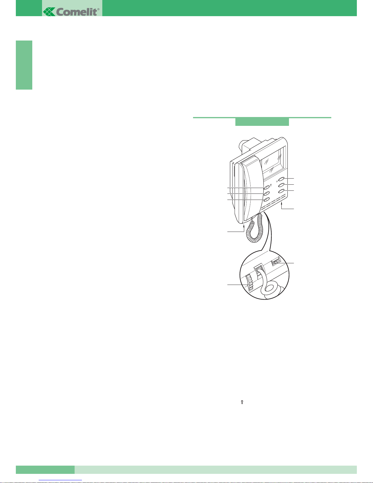
Monitor serie Videocom da semi-incasso (tubo corto)
Caratteristiche tecniche:
Monitor della serie Videocom di dimensioni 193x223x65, da
semi-incasso (49mm di profondità a muro), colore bianco RAL9010
con schermo B/W da 4,5” visione diretta.
Può essere installato sulla scatola Art. 4514 ma anche sulle scatole
da incasso per serie civili da 3 moduli DIN (Art. 4517) vedi pag. 5.
Da completare con staffa Art. 4714W/2. Il monitor è completo di:
1. Ganci di fissaggio alla staffa.
2. Regolazione luminosità (ruotare per variare l’intensità).
3. Regolazione volume chiamata
(spostare verso sinistra per aumentare volume).
4. Pulsante apriporta
().
5. Pulsante chiamata a centralino / libero (1).
6. Pulsante autoaccensione / richiesta video (2).
7. Pulsante attuatore * (3).
8. Pulsante Privacy * (4).
9. LED * (0).
* disponibili solo con scheda opzionale Art. 4703W.
Art. 4700W
1
2
4
3
4
5
6
9
1
3
2
1
8
7
GROUP S.P.A.
MT SB2 01
2
ITALIANO
Page 4
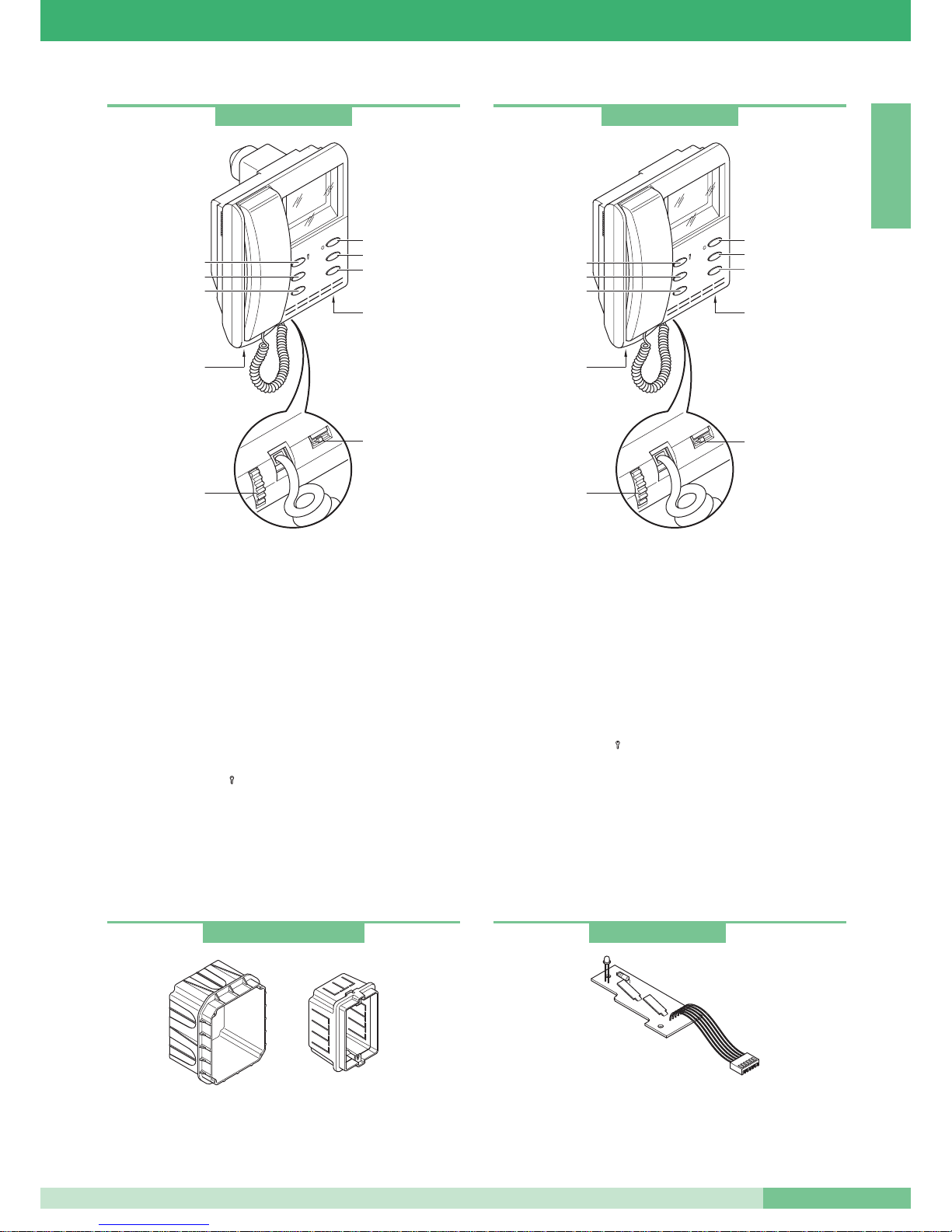
Monitor serie Videocom da semi-incasso (tubo-lungo)
Caratteristiche tecniche:
Monitor della serie Videocom di dimensioni 193x223x65, da
incasso (68mm di profondità a muro), colore bianco RAL9010
con schermo B/W da 4,5” visione diretta.
Installabile solo sulla scatola da incasso Art. 4514 vedi pag. 5.
Da completare con staffa Art. 4714W/2.
Il monitor è completo di:
1. Ganci di fissaggio alla staffa.
2. Regolazione luminosità (ruotare per variare l’intensità).
3. Regolazione volume chiamata.
(spostare verso sinistra per aumentare volume).
4. Pulsante apriporta
().
5. Pulsante chiamata a centralino / libero (1).
6. Pulsante autoaccensione / richiesta video (2).
7. Pulsante attuatore * (3).
8. Pulsante Privacy * (4).
9. LED * (0).
* disponibili solo con scheda opzionale Art. 4703W.
Art. 4514 scatola incasso monitor Art. 4700W e Art. 4700W/I.
Art. 4517 scatola serie civile 3 moduli DIN utilizzabile per incasso
monitor Art. 4700W.
Monitor serie Videocom da parete
Caratteristiche tecniche:
Monitor della serie Videocom di dimensioni 193x223x65, da parete,
colore bianco RAL9010 con schermo B/W da 4,5” visione diretta.
Da completare con staffa Art. 4714W/2.
Il monitor è completo di:
1. Ganci di fissaggio alla staffa.
2. Regolazione luminosità (ruotare per variare l’intensità).
3. Regolazione volume chiamata.
(spostare verso sinistra per aumentare volume).
4. Pulsante apriporta
().
5. Pulsante chiamata a centralino / libero (1).
6. Pulsante autoaccensione / richiesta video (2).
7. Pulsante attuatore * (3).
8. Pulsante Privacy * (4).
9. LED * (0).
* disponibili solo con scheda opzionale Art. 4703W
L’utilizzo del monitor Videocom vecchia serie 4701W può causare
problemi di funzionamento.
Art. 4700W/I
1
2
4
3
4
5
6
9
1
3
2
1
8
7
Art. 4701W/A
1
2
4
3
4
5
6
1
3
2
1
9
8
7
Art. 4514W e Art. 4517
Scheda pulsanti supplementari e LED
Scheda opzionale con 2 pulsanti supplementari e led di
segnalazione. Da inserire all’interno di tutti i monitor della serie
Videocom.
Art. 4703
MT SB2 01
3
MT SB2 01
ITALIANO
Page 5
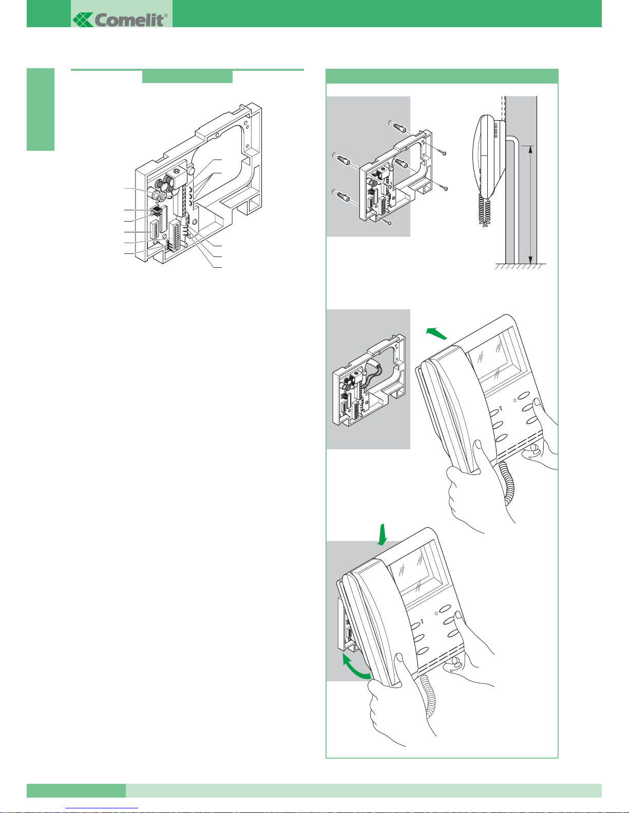
Staffa Simplebus2
Staffa di fissaggio del monitor consente l’installazione del monitor a
muro o tramite base da tavolo Art. 4712W (vedi pag. 5) e permette
il collegamento dei cavi di impianto.
Fornita di morsetti per collegamento chiamata da piano
(vedi variante G pag. 111), per la connessione di un dispositivo
di ripetizione chiamata (vedi SB2/D pag. 105) e per l’utilizzo del
pulsante 1 del monitor per usi vari (vedi variante E pag. 110).
È possibile inserire sino a 3 staffe con lo stesso codice utente
nel medesimo impianto (vedi pag. 98).
Compatibile con impianti Simplebus1.
Caratteristiche tecniche
Dimensioni: 158x121x24.
1. connettore staffa monitor.
2. morsetti connessione impianto:
0 +20V morsetti connessione Art. 1212/B.
L L connessione linea bus.
CFP CFP ingresso chiamata da piano.
P1 C1 pulsante per usi vari. Per avere un contatto pulito
NO, tagliare i cavallotti CV3 e CV4.
S+ S- morsetti per dispositivo ripetizione di chiamata.
3. CV5 Cavallotto chiusura video.
4. JP1 jumper di abilitazione richiesta video
(vedi variante F pag. 110).
5. CN2 connettore per programmazione.
6. Dip switches per programmazione codice utente.
7. CV2, CV1, CV7 cavallotti alimentazione monitor aggiuntivo
tramite Art. 1212/B (vedi variante SB2/A3 pag. 101).
8. CV3, CV4 cavallotti per liberare pulsante 1.
9. CV6 cavallotto selezione tipo di funzionamento
(Simplebus2 o Simplebus1).
10. JP2 jumper selezione tipo di funzionamento
(Simplebus2 o Simplebus1).
Art. 4714W/2
7
1
6
4
5
2
8
9
8
3
10
147
cm
1
2
3
4
1
2
1
2
3
4
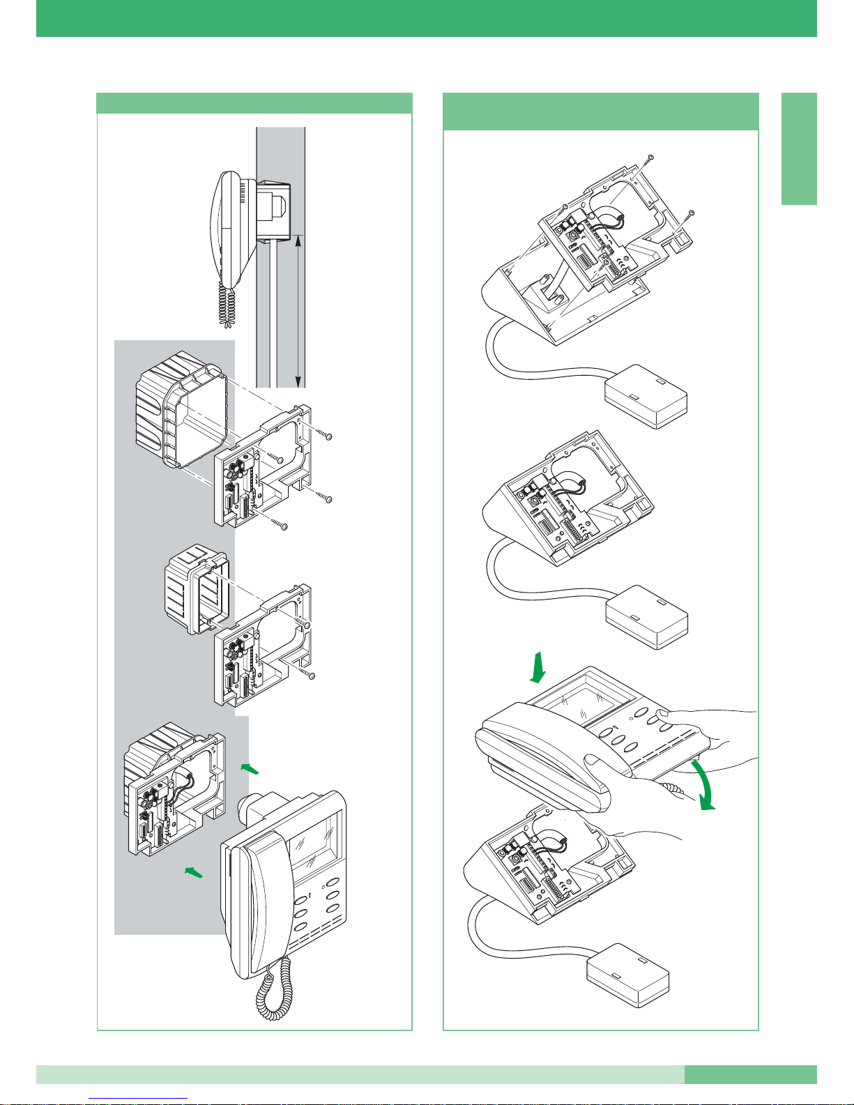
Installazione monitor Art. 4701W/A a parete
GROUP S.P.A.
MT SB2 01
4
ITALIANO
Page 6
145
cm
1
2
4
3
Art. 4514
Art. 4517
solo per monitor
Art. 4700W
Art.
4700W
4700W/I
Per monitor
Installazione monitor Art. 4700W e Art. 4700W/I a parete
2
1
4
3
1
2
Installazione base da tavolo Art. 4712W
per monitor Art. 4701W/A e Art. 4700W
MT SB2 01
5
MT SB2 01
ITALIANO
Page 7
POSTI INTERNI AUDIO
Citofono
Citofono della serie Okay di dimensioni 85x223x65 mm. Fornito
di pulsante apriporta e di pulsante chiamata centralino utilizzabile
come pulsante per usi vari negli impianti non provvisti di centralino
(vedi variante A pag. 108). Equipaggiato di serie di funzione
chiamata da piano (vedi variante B pag. 108). E’ possibile inserire
sino a tre citofoni con lo stesso codice utente nel medesimo
impianto. Per impostazione codice utente vedi “Programmazione
citofono Art. 2408W/A, 2428W e staffa Art. 4714W/2” a pag. 18.
Da utilizzare solo per impianti audio.
Caratteristiche tecniche:
1. Pulsante apriporta.
2. Pulsante chiamata centralino/pulsante per usi vari presente
in morsettiera (AB).
3. Morsetti connessione impianto:
L L connessione alla linea bus.
CFP CFP ingresso chiamata da piano.
AB pulsante normalmente dedicato a servizi vari.
Per avere contatto pulito NO tagliare i cavallotti CV1 e CV2.
4. Dip switches per impostazione codice utente (vedi pag. 19).
5. Trimmer regolazione volume microfono.
6. Trimmer regolazione volume suoneria.
147 cm
Art. 4704
1
2
4
3
Art. 4700W
1
2
+
-
+
-
MIC
5
6
3
4
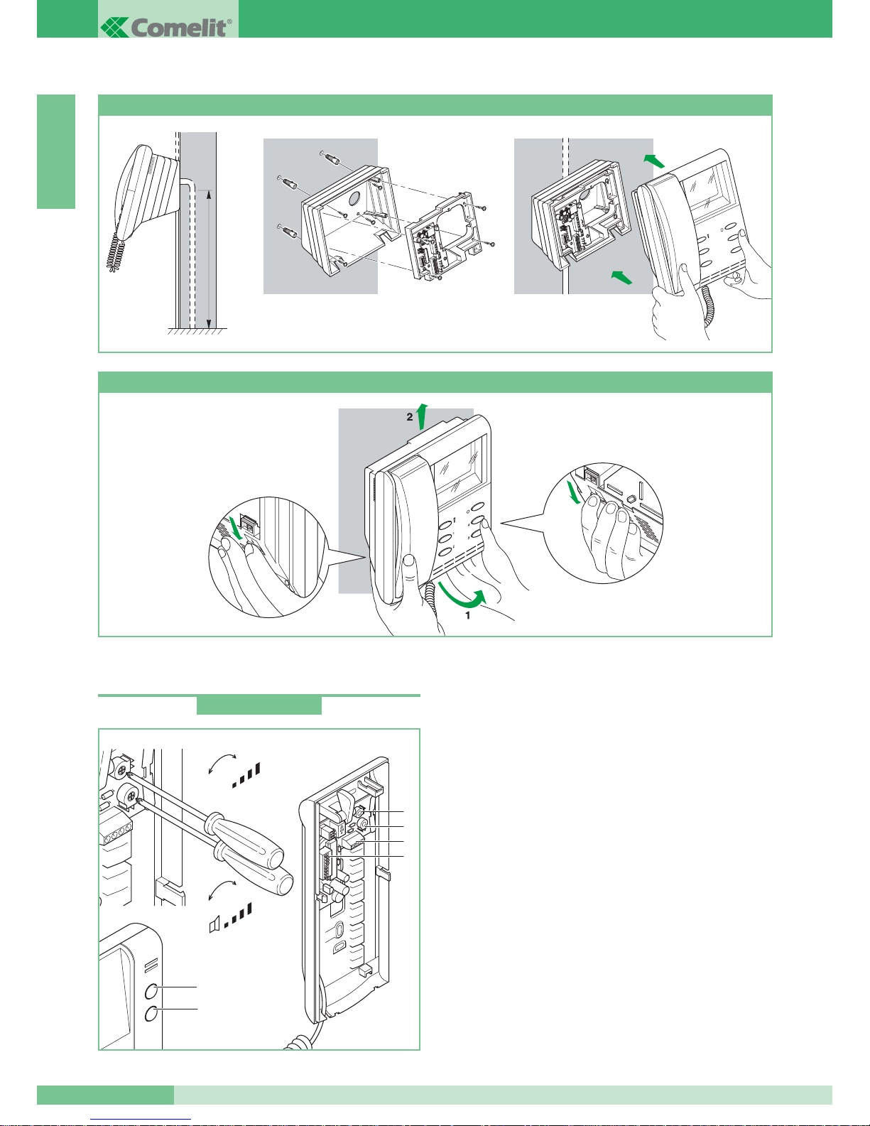
Installazione monitor semi-incasso Art. 4700W con adattatore da parete Art. 4704
Come togliere il monitor
Art. 2408W/A
GROUP S.P.A.
MT SB2 01
6
ITALIANO
Page 8

Citofono
Citofono come l’Art. 2408W/A con in più interruttore e Led
supplementare per servizio
Privacy o Dottore (apertura automatica
serratura a seguito di chiamata).
Vedi foglio tecnico interno all’articolo per la connessione ad impianto.
Citofono
Citofono della linea OKAY di dimensioni 85x223x65 mm. Fornito
di pulsante apriporta e di pulsante chiamata a centralino utilizzabile
per usi vari negli impianti non provvisti di centralino (vedi variante C
pag. 109). Equipaggiato di serie di funzione chiamata da piano
(vedi variante D pag. 109) e ripetizione chiamata (vedi SB2/D
pag. 105). Citofono da impiegare in impianti misti audio-video a
monte dell’Art. 4896 o in impianti audio quando si necessita di
funzione ripetizione di chiamata. E’ possibile inserire sino a tre
citofoni con lo stesso codice utente nel medesimo impianto.
Per modalità di inserimento citofoni aggiuntivi con stesso codice
utente vedi varianti SB2/A4 e SB2/A5 a pag. 102. Per impostazione
codice utente vedi “Programmazione citofono Art. 2408W/A,
2428W e staffa Art. 4714W/2” a pag. 18.
Caratteristiche tecniche:
1. Pulsante apriporta.
2. Pulsante chiamata centralino/pulsante per usi vari presente
in morsettiera (P1 C1).
3. Morsetti connessione impianto:
L L connessione alla linea bus.
CFP CFP ingresso chiamata da piano.
P1 C1 pulsante normalmente dedicato a servizi vari. Per avere
un contatto pulito NO tagliare i cavallotti CV2 e CV3.
S+ S- morsetti a cui connettere un dispositivo di ripetizione suoneria.
4. Dip switches per impostazione codice utente (vedi pag. 19).
5. Trimmer regolazione volume microfono.
6. Trimmer regolazione volume suoneria.
5
6
1
2
4
3
+
-
+
-
MIC
Art. 2410W
Art. 2428W
POSTAZIONI ESTERNE
In impianti Simplebus2 possono essere utilizzate postazioni esterne
della Serie Powercom, Vandalcom e Logicom. Per Vandalcom e
Logicom rifarsi al foglio tecnico FT/SB/01 e al Catalogo 50.
Portiere audio Serie Powercom
Composto dagli Art. 3320 + Art. 1602.
Portiere citofonico con morsettiera e doppio amplificatore,
altoparlante stagno e microfono ad electret. Volume microfono
ed altoparlante regolabili frontalmente sull’Art.1602 (vedi pag. 10);
possibilità di regolazione anche posteriore nel caso sia montato
sull’Art. 3320.Il microfono è removibile per migliorare la resa acustica
(vedi pag. 10). Pulsante di chiamata in lega di alluminio con etichetta
portanomi estraibile anteriormente.
Completo di microprocessore e Dip switches ad 8 posizioni per la
programmazione delle chiamate agli utenti. Per programmazione
pulsanti vedi pag. 20. Alimentazione 12V AC (utilizzare Art. 1195).
Funzione apriporta tramite switch elettronico a bordo (3A solo
alternata). Dimensioni 112x89,5x40 mm.
Portieri video Serie Powercom
Composto dagli Art. 3321 + Art. 4660.
Telecamera orientabile ad alta sensibilità pinhole CCD 1/4” B/W.
Illuminazione all’infrarosso (6 LED) . Completo di morsettiera
e portiere citofonico con doppio amplificatore, altoparlante stagno
e microfono ad electret.
Volume microfono ed altoparlante regolabili frontalmente
sull’Art.4660 (vedi pag. 10); possibilità di regolazione anche
posteriore nel caso sia montato sull’Art. 3321. Il microfono è
removibile per migliorare la resa acustica (vedi pag. 10 ). Pulsante
di chiamata in lega di alluminio con etichetta portanomi estraibile
anteriormente. Completo di microprocessore e Dip switches
ad 8 posizioni per la programmazione delle chiamate agli utenti.
Per programmazione pulsanti vedi pag. 20. Alimentazione 12V AC
(utilizzare Art. 1195).
Funzione apriporta tramite switch elettronico a bordo (3A solo
alternata). Dimensioni 112x89,5x40 mm.
MT SB2 01
7
MT SB2 01
ITALIANO
Page 9
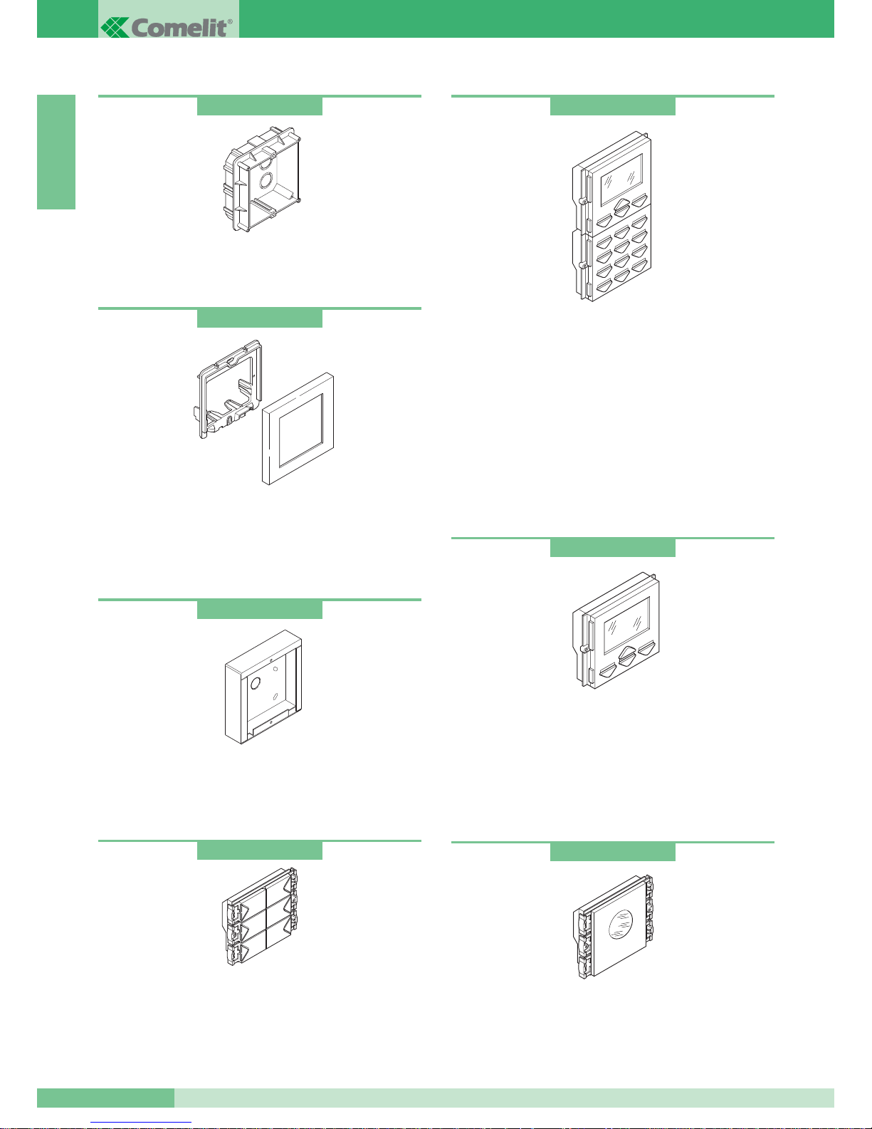
Scatole da incasso
Disponibili per 1, 2 e 3 moduli.
Dimensioni singolo modulo 127x127x45 mm.
Modulo di segnalazione di impianto occupato
Completo di led blu lampeggiante per indicazione visiva dello stato
di occupato. Il cartoncino trasparente è fornito neutro per inserire le
scritte in tutte le lingue. Dimensioni: 112x89,5x38 mm.
Modulo digitale di chiamata completo di rubrica elettronica
Completo di display LCD grafico 128x64 dots, tastiera 16 pulsanti
retroilluminati con LED blu. Funziona anche da chiave elettronica
a codice con la possibilità di inserire sino a 250 password.
È completo di modulo rubrica portanomi elettronica, che memorizza
400 nomi di utenti.
Lo scorrimento dei nomi avviene agendo su due pulsanti di ricerca
oppure digitando direttamente l’iniziale del nome o il codice utente.
Una volta visualizzato il nome dell’utente desiderato basta premere
il pulsante di chiamata. L’inserimento degli utenti avviene in modo
semplice mediante programmatore Art. 1230 oppure con il software
per PC Art. 1249. Dimensioni 112x180x40 mm.
Modulo rubrica elettronica
Modulo rubrica portanomi elettronica, con display grafico 128x64 dots.
Memorizza 400 nomi di utenti. Lo scorrimento dei nomi avviene agendo su
due pulsanti di ricerca. Una volta visualizzato il nome dell’utente
desiderato basta premere il pulsante di chiamata.
L’inserimento
degli
utenti avviene in modo semplice mediante programmatore Art. 1230
oppure con il software per PC Art. 1249. Dimensioni: 112x89,5x40 mm.
Moduli pulsanti di chiamata
Modulo pulsanti di chiamata dotati di micro-switch e realizzati in lega
di alluminio pressofuso e cromato. Led blu per illuminazione dei porta
nomi estraibili frontalmente Disponibili a 4 e 6 pulsanti. Dimensioni
112x89,5x40 mm. Per programmazione pulsanti vedi pag. 20.
Art. 3110
Art. 3323
Art. 3342
Art. 3346
Art. 3340
Art. 3311
Art. 3316
Telai portamoduli completi di cornice
Realizzati in pressofusione di alluminio e rivestiti di particolari
vernici resistenti in ambiente esterno.
Disponibili per 1, 2 e 3 moduli nei colori Grigio, Bianco,
Blu e Arancio. Dimensioni singolo modulo 125x125x15,5 mm.
Custodie da parete
Custodia in acciaio inox. Disponibile per 1, 2, 3, 4, 6 e 9 moduli.
Da parete anche per ambiente esterno. Utile quando non è possibile
incassare la scatola. Dimensioni singolo modulo 123x123x32,5 mm.
GROUP S.P.A.
MT SB2 01
8
ITALIANO
Page 10
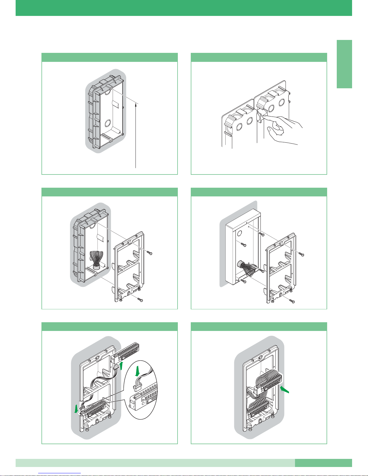
Istruzioni per installazione posto esterno audio e video
160 - 165 cm
Altezza scatola incasso Come accostare più scatole
Fissaggio del telaio su scatola da incasso
Fissaggio del telaio su custodia da parete
Collegamento cavetto a 4 poli Cablaggio morsettiera inserita o estratta
MT SB2 01
9
MT SB2 01
ITALIANO
Page 11

1
2
3
360˚
+
-
+
-
MIC
Montaggio, collegamenti
e regolazioni gruppo audio-video
Inserimento moduli
2
3
5
1
4
Posizione alternativa del microfono
Montaggio /Smontaggio frontalini
Fissaggio cornice
C
arla
R
ossi
Montaggio/Smontaggio cartellini
open
close
GROUP S.P.A.
MT SB2 01
10
ITALIANO
Page 12
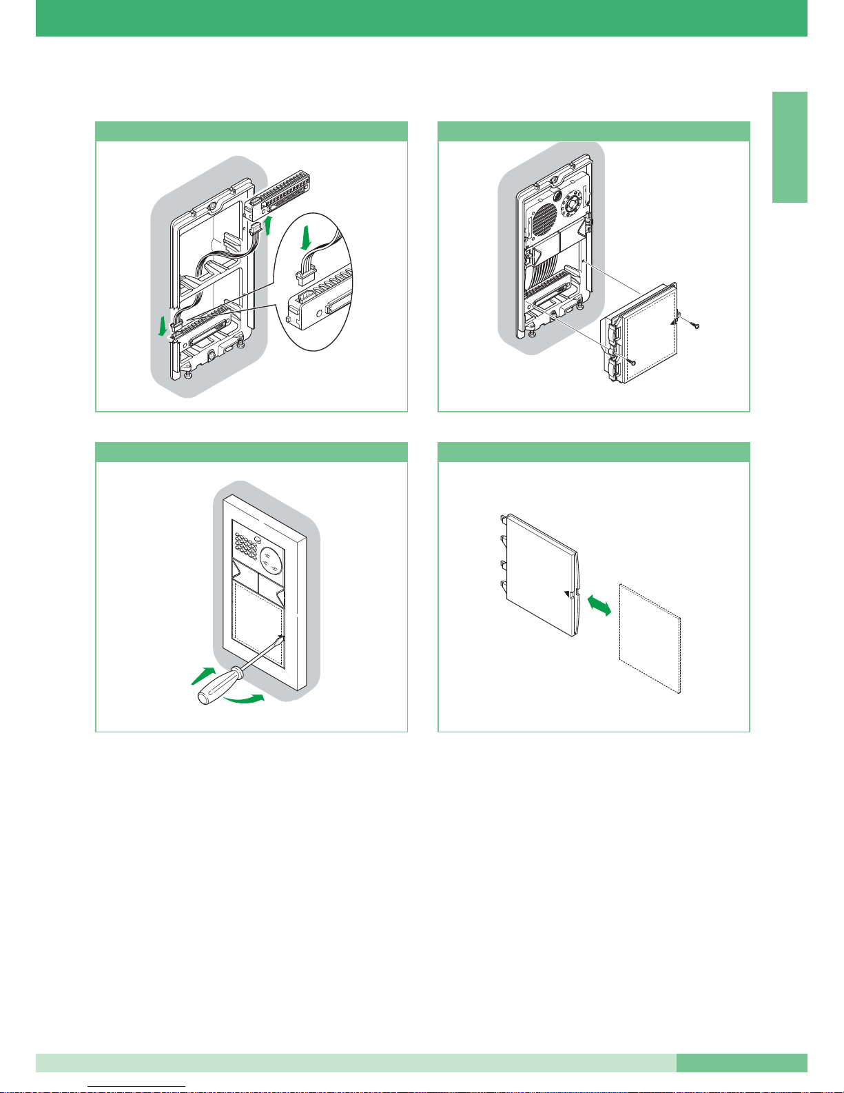
Collegamento cavetto a 4 poli
10
Inserimento modulo
2
1
10
Estrazione porta cartellino
15
Inserimento/estrazione cartellino
Istruzioni per montaggio moduli informativi Art. 3326, Art. 3344 e Art. 3346
MT SB2 01
11
MT SB2 01
ITALIANO
Page 13
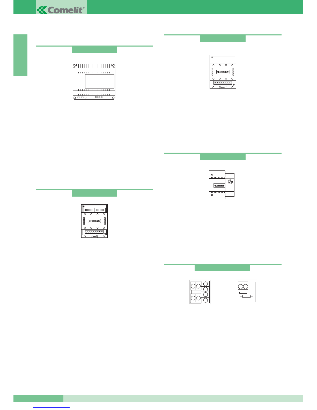
ALIMENTATORI E ACCESSORI
Trasformatore per Miscelatore-alimentatore
Trasformatore 65VA. (T 1’on / 5’off).
Primario 230VAC
Secondario: OUT1: 36VAC 1,5A
OUT2: 14VAC 1A
Il trasformatore è equipaggiato con PTC interno di protezione.
Dimensioni: 107x90x60 (8 moduli DIN).
Scambio
Alimentazione 12VAC-20VDC.
Dimensioni 66x85x35mm (4 moduli DIN).
Morsetti connessione impianto:
~ ~ * alimentazione 12VAC-20VDC.
LS LS ingresso linea bus posto esterno secondario.
LP LP ingresso linea bus posto esterno principale.
LM LM uscita linea bus di montante.
Per programmazione scambio vedi pag. 18.
Alimentatore per monitor aggiuntivo
Alimentatore 15VA (interm.).
Ingresso: 230VAC
Uscita: 0- 20VDC 700mA
Il trasformatore è equipaggiato con PTC interno di protezione.
Dimensioni: 87x105x65 (5 moduli DIN).
Art. 1246
Morsetto di derivazione e terminazione di linea
Vedi pag. 20 per configurazione Art. 1216 a seconda del cavo
utilizzato. Morsetti connessione impianto:
Lin Lin: ingresso linea montante.
Lout Lout: uscita linea montante.
LM LM: linea montante derivata verso il monitor/citofono.
+ +: morsetti connessione alimentazione per compatibilità
impianti Simplebus1.
Art. 1212/B
Relè
Relè 12-24V DC-AC 5A per usi generali. Direttamente comandabile
dall’uscita di ripartizione chiamata della staffa Art. 4714W/2 o
citofoni Art. 2428W. Dimensioni: 66x85x35 mm (4 moduli DIN).
Morsetti connessione impianto:
+ - alimentazione relè.
C-NO-NC contatti relè.
Art. 1122/A
Art. 1214/2 e Art. 1216
Art. 1214/2
Art. 1216
Art. 1224
GROUP S.P.A.
MT SB2 01
12
ITALIANO
Page 14

Trasformatore
Trasformatore 60VA (interm).
Primario 230VAC
Secondario: OUT1: 0-12V 1,5A
OUT2: 0-12V 1,5A
Il trasformatore è equipaggiato con fusibile interno di protezione.
Dimensioni: 87x105x65 (5 moduli DIN).
Miscelatore-alimentatore
Il Miscelatore-alimentatore Art. 4896 è contenuto in una scatola
12 moduli DIN.
Dimensioni: 208x140x65 mm.
Per poter accedere ai morsetti di collegamento togliere i coperchi
laterali come in figura.
Art. 4896
Art. 1195
4
1
3
4
2
JP1
JP2
L’Art. 4896 deve essere alimentato tramite trasformatore Art.1246.
Eseguire le operazioni di cablaggio e collegamento dell’impianto
disinserendo l’alimentazione di rete.
Essendo fornito di PTC di protezione dopo un cortocircuito,
per riattivare togliere l’alimentazione per circa un minuto.
Inserire la linea in ingresso dal posto esterno, e quindi dare
alimentazione anche al modulo Miscelatore-alimentatore Art. 4896.
Il dispositivo consente di alimentare al massimo un monitor ed è in
grado di gestire al
MAX 100 utenti.
Morsetti connessione impianto:
1. Lin Lin connessione alla linea proveniente dal posto esterno.
2.
0V 36V connessione ai morsetti OUT1 del trasformatore Art. 1246.
0V 14V connessione ai morsetti OUT2 del trasformatore Art. 1246.
3.
L1 L1 uscita derivazione 1 di montante.
L2 L2 uscita derivazione 2 di montante.
L3 L3 uscita derivazione 3 di montante.
L4 L4 uscita derivazione 4 di montante.
4. Jumper da impostare a seconda del numero di utenti totali
connessi al Miscelatore-alimentatore Art. 4896.
JP1 e JP2 in
posizione 3 per impianti con utenti da 0 a 15.
JP1 e JP2 in posizione 2 per impianti con utenti da 16 a 35.
JP1 e JP2 in posizione 1 per impianti con utenti da 36 a 100.
JP1 - JP2
2
3
1
MT SB2 01
13
MT SB2 01
ITALIANO
Page 15
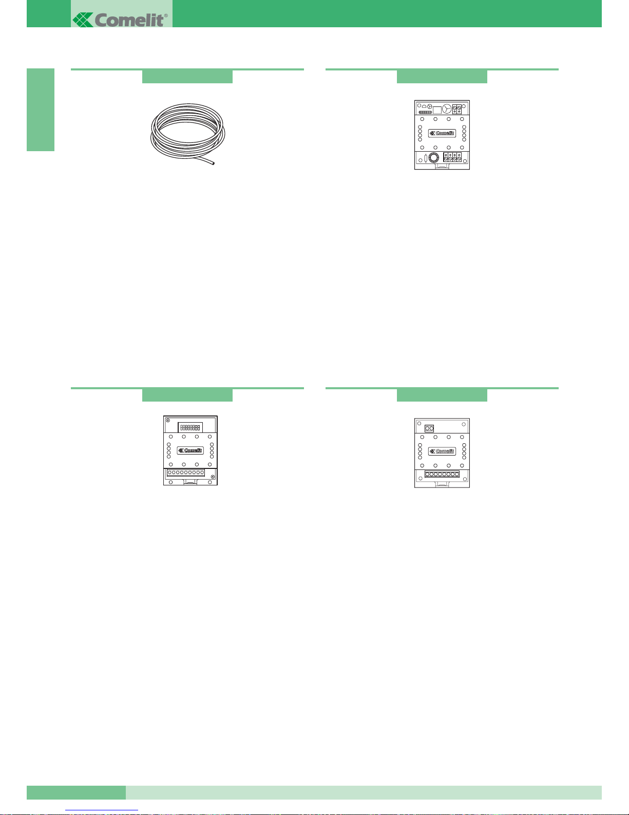
Amplificatore di linea
Amplificatore per impianti video Simplebus1.
Rigenera il segnale di montante relativamente alla componente
video. Alimentazione: 12V AC o 20V DC.
Da montare solo su tratta di impianto in ingresso ai Miscelatorialimentatori Art. 4896.
Dimensioni: 66x85x35 mm (4 moduli DIN).
Morsetti connessione impianto:
Lin Lin: ingresso linea montante.
Lout Lout: uscita linea montante.
~+ ~-: alimentazione modulo.
Art. 4833/A
Concentratore di linea
Concentratore di linea per impianto Simplebus video.
Consente la distribuzione del segnale su 4 montanti.
Da montare solo su tratta di impianto in ingresso ai Miscelatorialimentatori Art. 4896.
Dimensioni: 66x85x35 mm (4 moduli DIN).
Morsetti connessione impianto:
Lin Lin: ingresso linea montante.
L1 L1: uscita derivazione1 di montante.
L2 L2: uscita derivazione2 di montante.
L3 L3: uscita derivazione3 di montante
(tagliare la resistenza prima di inserire i cavi).
L4 L4: uscita derivazione4 di montante
(tagliare la resistenza prima di inserire i cavi).
Art. 4834/2
Cavo comelit Simplebus2
Cavo specifico per impianti Simplebus2: è composto da due
conduttori di sezione 1mm2intrecciati di colore rosso e nero.
Disponibili in matasse da 100 e 500 m.
Rele per servizi vari
Alimentazione 12VAC, 20VDC.
Portata rele 10A.
Questo accessorio consente:
• servizio ripetizione suoneria.
• servizio comando relè da posto interno in impianti sprovvisti
di centralino.
• servizio luci scale.
• servizio apriporta secondario.
Per cablaggio e spiegazione servizi si veda documentazione
dell’Art. 1254.
Art. 4577
Art. 1254
GROUP S.P.A.
MT SB2 01
14
ITALIANO
Page 16
REGOLE DI INSTALLAZIONE
Regole d’installazione per impianti videocitofonici
Evitare di porre i fili di montante in prossimità di cavi di
alimentazione (220/380V).
Nelle diramazioni verso ogni utente inserire sul montante il
morsetto Art. 1214/2 fornito a corredo della staffa Art. 4714W/2 o
acquistabile separatamente per i citofoni Art. 2428W.
Terminare ogni montante o diramazione con l’Art. 1216 fornito a
corredo del Miscelatore-alimentatore Art. 4896 e del modulo video
Art. 4660. In funzione del cavo utilizzato per il montante impostare
la chiusura sull’Art. 1216 come indicato in tabella a pag. 20.
In funzione del cavo utilizzato per il montante valutare la distanza
massima raggiungibile tra Alimentatore-miscelatore Art. 4896
e monitor più lontano e tra morsetto di derivazione Art. 1214/2
e monitor più lontano.
In funzione del cavo utilizzato per il collegamento valutare la
distanza massima raggiungibile tra il posto esterno video e il
Miscelatore-alimentatore Art. 4896. Riferirsi alle tabelle a pag. 16
per valutare le distanze in funzione dei conduttori.
Ogni Art.4896 può gestire
MAX 4 diramazioni di montante
vedi variante SB2/B pag. 103.
Nel caso di impianti con porte principali e secondarie (vedi schema
SB2V/EN/112 pag. 97) è necessario impiegare il concentratore di
linea Art. 4834/2 e lo scambio Art. 1224.
Nel caso di unica porta è possibile connettere
fino a 4
Miscelatori-alimentatori Art. 4896 dopo l’Art. 4834/2 (vedi
schema SB2V/012 pag. 94).
Ogni Art. 4834/2 consente al
MAX 4 diramazioni: nel caso
si necessiti di più diramazioni (fino a 16) è necessario mettere
in cascata due Art. 4834/2. L’Art. 4834/2 aggiunto deve essere
preceduto dal rispettivo amplificatore di segnale video
Art. 4833/A (vedi variante SB2/C pag. 104). Si possono inserire
sino al
MAX 2 Art.4834/2 in cascata.
Il numero MAX di utenti collegabili ad un singolo Miscelatorealimentatore Art. 4896 è di 100
indipendentemente che siano
divisi su un singolo montante o su più diramazioni di montante
(es: 100 utenti su singolo montante o 25 utenti su ognuno delle
4 diramazioni di montante.)
È possibile connettere
sino a 25 monitor in cascata per
ogni diramazione di montante (vedi variante SB2/G pag. 106);
in questo caso per determinare la distanza MAX tra posto
esterno e ultimo monitor della cascata fare riferimento alla tabella
di pag. 16 colonna
A.
Il collegamento tra più monitor con stesso codice utente (MAX 3)
può avvenire in cascata o in derivazione dal montante seguendo
le varianti SB2/A1-A2-A3-A4-A5 (vedi pagg. 99-100-101-102).
I citofoni Art. 2428W con stesso codice utente di monitor devono
essere derivati direttamente dal montante tramite Art. 1214/2.
L’Art. 4896 alimenta
un solo monitor per ogni chiamata,
quindi per impianti con più monitor con lo stesso codice utente
è necessario impostare i monitor aggiuntivi come secondari
o alimentare separatamente tramite Art.1212/B ogni monitor
supplementare (vedi pagg. 99-100-101).
Impostare i cavallotti ed i jumper sulla staffa Art. 4714W/2
come mostrato nelle varianti agli schemi base SB2/A1-A2-A3
a seconda della configurazione che si vuole ottenere.
Le telecamere dei posti esterni non devono essere rivolte
verso fonti di luce diretta (es. lampade, luce solare,
superfici riflettenti, ecc …)
MT SB2 01
15
MT SB2 01
ITALIANO
Page 17
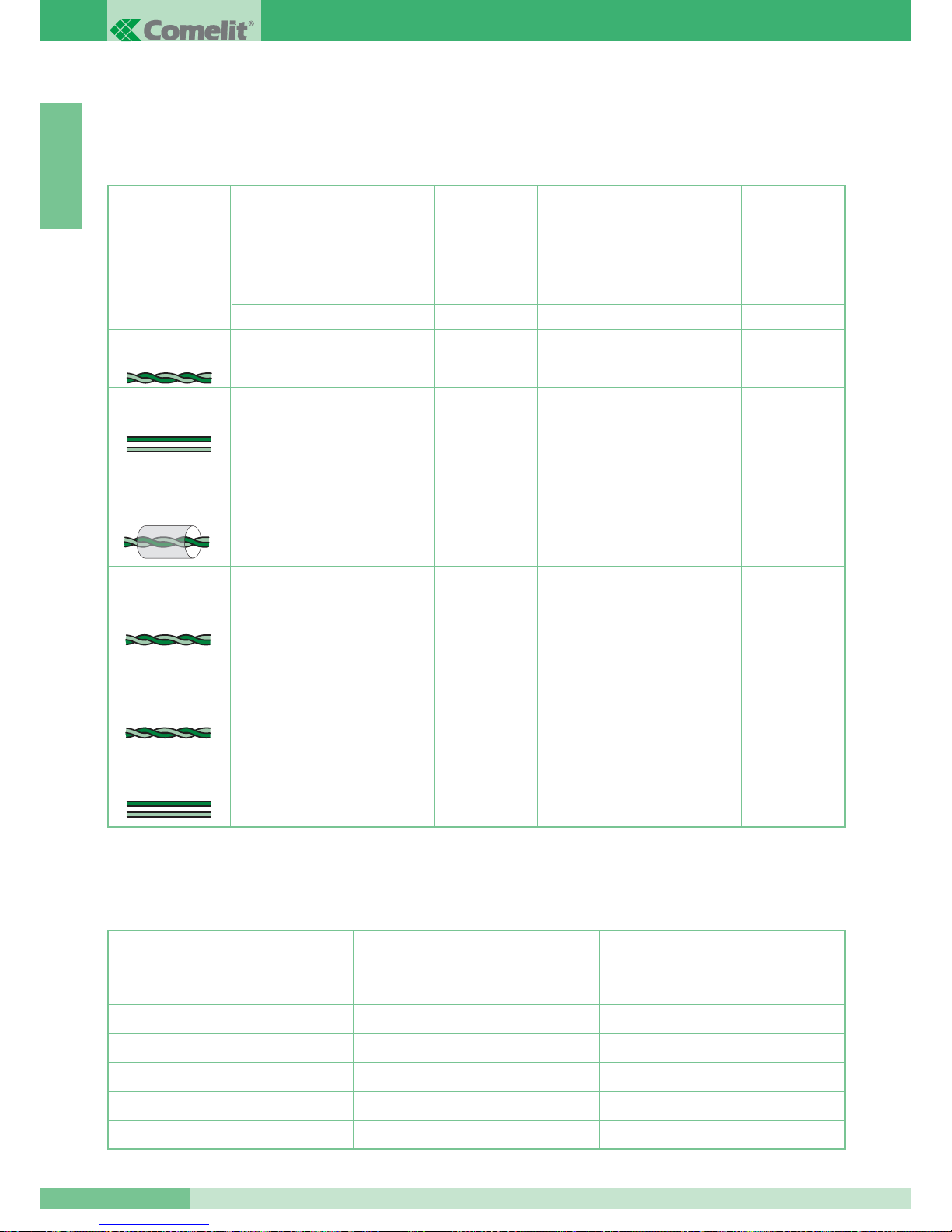
Distanze massime e caratteristiche dei conduttori
Il collegamento degli apparecchi è di tipo non polarizzato. L’impiego di conduttori con caratteristiche diverse da quelli prescritti, non garantisce
il raggiungimento di determinate distanze di impianto e la buona qualità del segnale video , per cui utilizzare esclusivamente cavi descritti
nelle tabelle seguenti.
Distanze massime raggiungibili per i conduttori di alimentazione monitor aggiunto e posto esterno
Tipo di cavo
Doppino telefonico
twistato sez. 0,28 mm
2
(Ø 0,6 mm)*
Cavo UTP5 cat 5
AWG 24 sez. 0,2 mm
2
(Ø 0,5 mm)*
200 m
150 m
120 m
100 m
200 m
100 m
80 m
150 m
200 m
100 m
80 m
150 m
200 m
100 m
80 m
150 m
150 m
80 m
50 m
100 m
ABCDE
Distanza MAX
tra Miscelatore
Art. 4896
e posto interno.
Distanza MAX
tra posto esterno
e Miscelatore.
Art. 4896
Distanza MAX
tra posto esterno
e Art. 4833/A.
Distanza MAX
tra Art. 4833/A
e Miscelatore
Art. 4896.
Distanza MAX
tra posto esterno
e Miscelatore o
amplifcatore
Art. 4833/A con un
Art. 4834/2 inserito.
60 m
40 m
30 m
40 m
80 m 150 m 150 m 150 m 100 m 40 m
H
Distanza MAX
tra morsetto di
derivazione
Art. 1214/2
e posto interno.
Cavo Comelit Art. 4577
sez. 1 mm
2
(
Ø 1,2 mm)
Cavo bifilare sez.
1,5 mm
2
(
Ø 1,4 mm)**
Cavo intrecciato e
schermato sez. 1 mm
2
(
Ø 1,2 mm)*
Sezione del conduttore
4 m
10 m
20 m
30 m
40 m
10 m
25 m
50 m
100 m
150 m
FG
Distanza MAX tra trasformatore
Art. 1195 e posto esterno.
Distanza MAX tra alimentatore
Art. 1212/B e posto interno.
0,28 mm
2
(Ø0,6 mm)
0,5 mm
2
(Ø0,8 mm)
1 mm
2
(Ø1,2 mm)
1,5 mm
2
(Ø1,4 mm)
2 mm
2
(Ø1,6 mm)
Cavo bifilare sez.
0,5 mm
2
(Ø0,8 mm)
**
120 m 100 m 100 m 100 m 80 m 40 m
* Nel caso si utilizzi un cavo multicoppiola usare una sola delle coppiole disponibili. Nel caso sia necessario per diminuire le cadute resistive
utilizzare la singola coppiola come singolo filo.
** Nel caso si utilizzi un cavo multipolare usare solo due dei fili disponibili e non utilizzare mai fili in parallelo.
GROUP S.P.A.
MT SB2 01
16
ITALIANO
Page 18
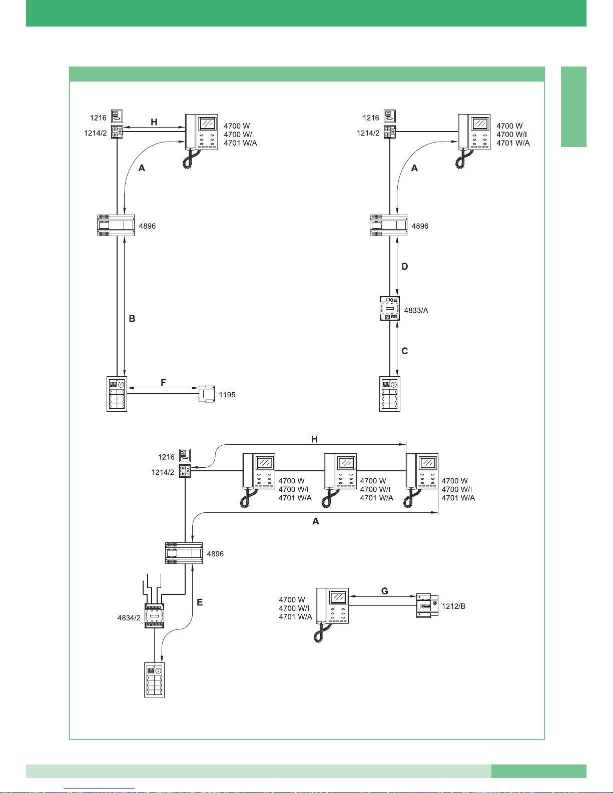
Figure per le distanze
MT SB2 01
17
MT SB2 01
ITALIANO
Page 19
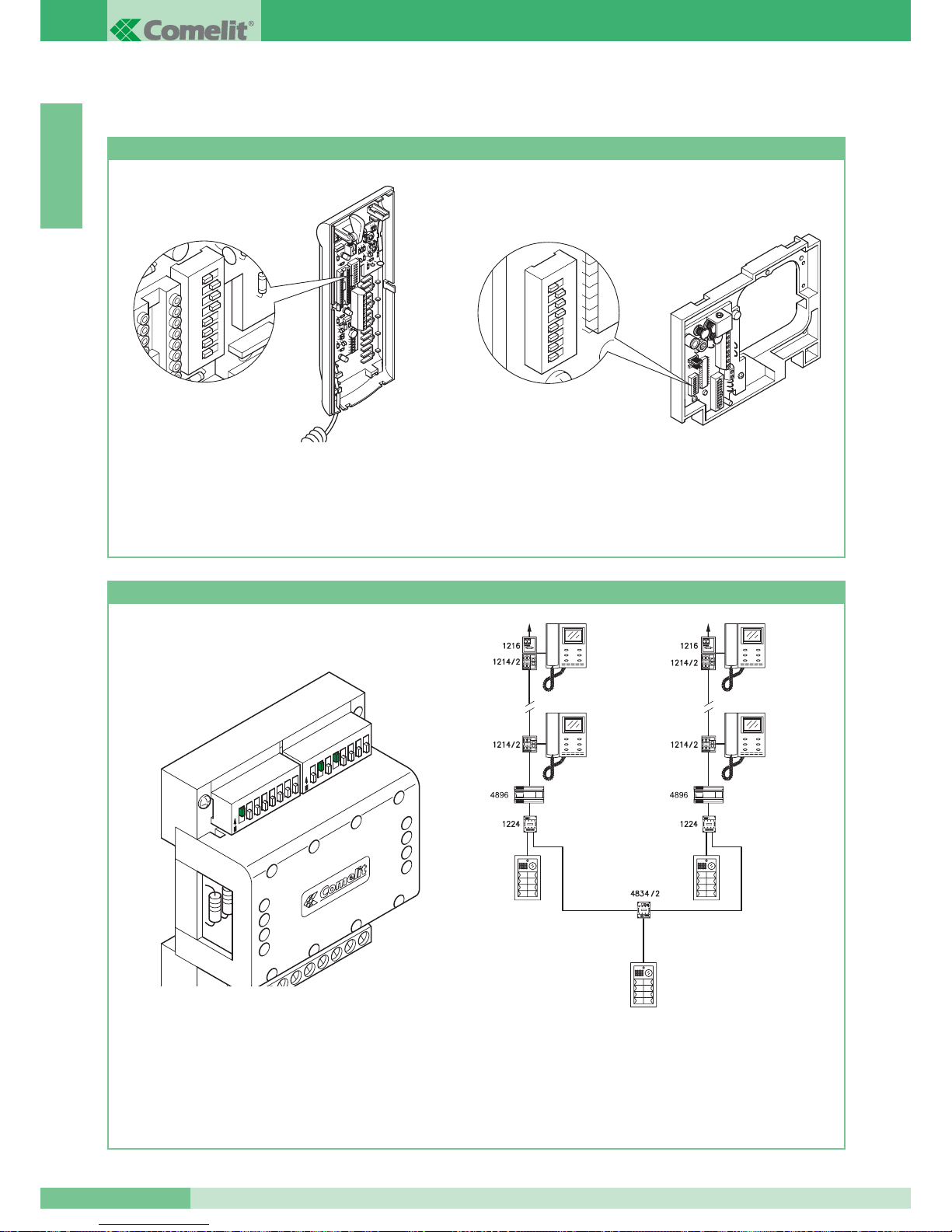
CONFIGURAZIONE DEI DISPOSITIVI
Programmazione citofono Art. 2408W/A, 2410W, 2428W e staffa Art. 4714W/2
• Ogni citofono o staffa del sistema viene identificato
mediante il proprio codice; tale codice deve essere impostato
mediante il Dip switches presente sulla scheda citofonica
oppure sulla staffa (vedi figure).
• Il codice utente deve essere impostato secondo la corrispondenza
descritta nella tabella di programmazione di pag. 19.
• La codifica può avvenire in qualsiasi momento, anche senza
alimentazione.
1 2
3
4 5
6 7
8
1 2
3
4 5
6 7
8
Programmazione scambio Art. 1224
• Ogni modulo scambio è dotato di una coppia di Dip switches
ad 8 selettori (vedi figura). I due Dip switches definiscono
il range minimo MIN e massimo MAX di codici che possono
essere riconosciuti dallo scambio.
• Si ricordi che i Dip switches MIN e MAX definiscono rispettivamente
i codici utente più basso e più alto collegabili al montante.
•Per l’impostazione dei valori desiderati si faccia riferimento
alla tabella di pag. 19.
• Scambi distinti devono gestire intervalli di codici non sovrapposti.
PORTA PRINCIPALE DAL N° 1÷20.
SCALA A SCALA B
4700 W
4700 W/I
4701 W/A
4700 W
4700 W/I
4701 W/A
N° 1÷10 N° 11÷20
4700 W
4700 W/I
4701 W/A
4700 W
4700 W/I
4701 W/A
MAX
MIN
1
2
3
4
5
6
7
8
1
2
3
4
5
6
7
8
O
N
O
N
• Esempio di codifica scambio Art. 1224 della scala A
numero minimo 1, numero massimo 10.
GROUP S.P.A.
MT SB2 01
18
ITALIANO
Page 20
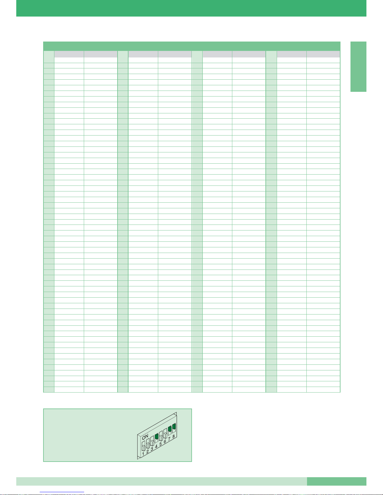
Tabella di programmazione dei Dip switches
11 61 1,3,4,5,6 121 1,4,5,6,7 181 1,3,5,6,8
22 62 2,3,4,5,6 122 2,4,5,6,7 182 2,3,5,6,8
3 1,2 63 1,2,3,4,5,6 123 1,2,4,5,6,7 183 1,2,3,5,6,8
43 64 7 124 3,4,5,6,7 184 4,5,6,8
5 1,3 65 1,7 125 1,3,4,5,6,7 185 1,4,5,6,8
6 2,3 66 2,7 126 2,3,4,5,6,7 186 2,4,5,6,8
71,2,3 67 1,2,7 127 1,2,3,4,5,6,7 187 1,2,4,5,6,8
84 68 3,7 128 8 188 3,4,5,6,8
9 1,4 69 1,3,7 129 1,8 189 1,3,4,5,6,8
10 2,4 70 2,3,7 130 2,8 190 2,3,4,5,6,8
11 1,2,4 71 1,2,3,7 131 1,2,8 191 1,2,3,4,5,6,8
12 3,4 72 4,7 132 3,8 192 7,8
13 1,3,4 73 1,4,7 133 1,3,8 193 1,7,8
14 2,3,4 74 2,4,7 134 2,3,8 194 2,7,8
15 1,2,3,4 75 1,2,4,7 135 1,2,3,8 195 1,2,7,8
16 5 76 3,4,7 136 4,8 196 3,7,8
17 1,5 77 1,3,4,7 137 1,4,8 197 1,3,7,8
18 2,5 78 2,3,4,7 138 2,4,8 198 2,3,7,8
19 1,2,5 79 1,2,3,4,7 139 1,2,4,8 199 1,2,3,7,8
20 3,5 80 5,7 140 3,4,8 200 4,7,8
21 1,3,5 81 1,5,7 141 1,3,4,8 201 1,4,7,8
22 2,3,5 82 2,5,7 142 2,3,4,8 202 2,4,7,8
23 1,2,3,5 83 1,2,5,7 143 1,2,3,4,8 203 1,2,4,7,8
24 4,5 84 3,5,7 144 5,8 204 3,4,7,8
25 1,4,5 85 1,3,5,7 145 1,5,8 205 1,3,4,7,8
26 2,4,5 86 2,3,5,7 146 2,5,8 206 2,3,4,7,8
27 1,2,4,5 87 1,2,3,5,7 147 1,2,5,8 207 1,2,3,4,7,8
28 3,4,5 88 4,5,7 148 3,5,8 208 5,7,8
29 1,3,4,5 89 1,4,5,7 149 1,3,5,8 209 1,5,7,8
30 2,3,4,5 90 2,4,5,7 150 2,3,5,8 210 2,5,7,8
31 1,2,3,4,5 91 1,2,4,5,7 151 1,2,3,5,8 211 1,2,5,7,8
32 6 92 3,4,5,7 152 4,5,8 212 3,5,7,8
33 1,6 93 1,3,4,5,7 153 1,4,5,8 213 1,3,5,7,8
34 2,6 94 2,3,4,5,7 154 2,4,5,8 214 2,3,5,7,8
35 1,2,6 95 1,2,3,4,5,7 155 1,2,4,5,8 215 1,2,3,5,7,8
36 3,6 96 6,7 156 3,4,5,8 216 4,5,7,8
37 1,3,6 97 1,6,7 157 1,3,4,5,8 217 1,4,5,7,8
38 2,3,6 98 2,6,7 158 2,3,4,5,8 218 2,4,5,7,8
39 1,2,3,6 99 1,2,6,7 159 1,2,3,4,5,8 219 1,2,4,5,7,8
40 4,6 100 3,6,7 160 6,8 220 3,4,5,7,8
41 1,4,6 101 1,3,6,7 161 1,6,8 221 1,3,4,5,7,8
42 2,4,6 102 2,3,6,7 162 2,6,8 222 2,3,4,5,7,8
43 1,2,4,6 103 1,2,3,6,7 163 1,2,6,8 223 1,2,3,4,5,7,8
44 3,4,6 104 4,6,7 164 3,6,8 224 6,7,8
45 1,3,4,6 105 1,4,6,7 165 1,3,6,8 225 1,6,7,8
46 2,3,4,6 106 2,4,6,7 166 2,3,6,8 226 2,6,7,8
47 1,2,3,4,6 107 1,2,4,6,7 167 1,2,3,6,8 227 1,2,6,7,8
48 5,6 108 3,4,6,7 168 4,6,8 228 3,6,7,8
49 1,5,6 109 1,3,4,6,7 169 1,4,6,8 229 1,3,6,7,8
50 2,5,6 110 2,3,4,6,7 170 2,4,6,8 230 2,3,6,7,8
51 1,2,5,6 111 1,2,3,4,6,7 171 1,2,4,6,8 231 1,2,3,6,7,8
52 3,5,6 112 5,6,7 172 3,4,6,8 232 4,6,7,8
53 1,3,5,6 113 1,5,6,7 173 1,3,4,6,8 233 1,4,6,7,8
54 2,3,5,6 114 2,5,6,7 174 2,3,4,6,8 234 2,4,6,7,8
55 1,2,3,5,6 115 1,2,5,6,7 175 1,2,3,4,6,8 235 1,2,4,6,7,8
56 4,5,6 116 3,5,6,7 176 5,6,8 236 3,4,6,7,8
57 1,4,5,6 117 1,3,5,6,7 177 1,5,6,8 237 1,3,4,6,7,8
58 2,4,5,6 118 2,3,5,6,7 178 2,5,6,8 238 2,3,4,6,7,8
59 1,2,4,5,6 119 1,2,3,5,6,7 179 1,2,5,6,8 239 1,2,3,4,6,7,8
60 3,4,5,6 120 4,5,6,7 180 3,5,6,8
*240 5,6,7,8
*NOTA: il codice 240 è riservato per il centralino.
ESEMPIO impostazione codice 200.
Cod.ut.
Dip switches su ON
Nome utente
Cod.ut.
Dip switches su ON
Nome utente
Cod.ut.
Dip switches su ON
Nome utente
Cod.ut.
Dip switches su ON
Nome utente
MT SB2 01
19
MT SB2 01
ITALIANO
Page 21
ITALIANO
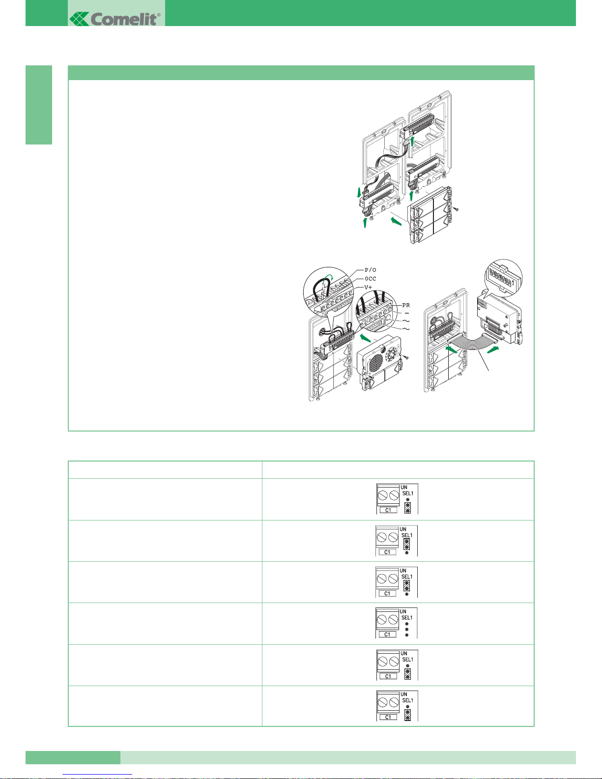
Programmazione pulsanti con gruppo audio Art. 1602 e video Art.4660 e moduli Art. 3323/4 e 3323/6
1. Connettere le morsettiere dei moduli Art. 3323/4 e Art. 3323/6
tra loro e con la morsettiera del gruppo Art. 4660 o Art. 1602
utilizzando gli appositi cavetti. Inserire i moduli Art. 3323/4
e Art. 3323/6 sulle relative morsettiere (figura 1).
2. Sulla morsettiera del modulo Art. 4660 o Art. 1602 collegare
l’alimentazione su
~~ , connettere PR a -- e spostare P/O
da OCC a V+ (figura 2) utilizzando i jumper presenti
sulla morsettiera stessa. Connettere la morsettiera al modulo
Art. 4660 o Art. 1602 assemblato come indicato precedentemente.
(attenzione i moduli Art. 3323/4 e Art. 3323/6 da programmare
devono essere già posizionati) (figura 2).
NOTA: per il collegamento tra la morsettiera e il modulo
Art. 4660 o Art. 1602 in fase di programmazione è possibile
usare il cavetto Art. 3309 disponibile come accessorio
opzionale (figura 3).
3. Impostare il Dip switches posto sul retro del modulo audio
con lo stesso codice assegnato al citofono o monitor secondo
la corrispondenza descritta nella tabella di programmazione a
pag. 19.
4. Premere il pulsante che si desidera associare alla chiamata
del citofono. L’avvenuta programmazione viene segnalata
con un tono di conferma.
5. Al termine della programmazione rimettere i jumper
nelle posizioni iniziali, PR su PR e P/O su OCC.
Impostazione posto esterno principale o secondario
I moduli Art. 4660 e Art. 1602 funzionano normalmente come
posto esterno principale (segnalazione di occupato a tempo).
Per impostarli come posto esterno secondario (segnalazione
di occupato attiva per tutta la durata di impegno del montante)
è necessario mettere tutti i Dip switches del selettore su ON.
Fig. 1
Fig. 3
Art. 3309
Fig. 2
1
2
3
4
5
6
7
8
O
N
GROUP S.P.A.
MT SB2 01
20
Tabella Impostazioni dell’Art. 1216 in funzione del tipo di cavo di connessione utilizzato
Tipo di cavo Impostazione Art. 1216
Cavo Comelit Art. 4577 sez. 1 mm
2
(Ø 1,2 mm)
2
2
1
1
Cavo bifilare sez. 1,5 mm2(Ø 1,4 mm)
Cavo intrecciato e schermato sez. 1 mm
2
(Ø 1,2 mm)
Doppino telefonico twistato sez. 0,28 mm
2
(Ø 0,6 mm)
Cavo UTP5 cat 5 AWG 24 sez. 0,2 mm
2
(Ø 0,5 mm)
Cavo bifilare sez. 0,5 mm2(Ø 0,8 mm)
2
Page 22

ITALIANO
NOTE DI FUNZIONAMENTO
• Il visitatore premendo il tasto di chiamata aziona la suoneria
del posto interno.
• Al posto esterno si ha un tono di avvenuta chiamata; se in impianti
con più ingressi non si ode il tono di conferma chiamata, significa
che un’altra conversazione è in atto verso un altro posto esterno
installato sullo stesso montante. Nel caso sia installato l’Art. 3346,
modulo di segnalazione impianto occupato, attendere sino
allo spegnimento del modulo prima di richiamare.
Nel caso sia installato l’Art. 3340 l’indicazione di impianto occupato
è visualizzata sul display.
• Al posto interno si entra in comunicazione sollevando
il microtelefono.
• Il tasto contraddistinto dal simbolo della chiave agisce
sull’elettroserratura del posto esterno attivandola per circa
2 sec.
• In impianti videocitofonici premendo il tasto di chiamata sul posto
esterno si accendono i LED all’infrarosso (non visibile all’occhio
umano) per l’illuminazione del soggetto; l’immagine rimane sul
monitor per circa 90 sec.
• Per regolazione volume microfono e volume suoneria dei citofoni
vedi pag. 6, 7.
• Per regolazione volume suoneria dei monitor vedi pag. 2, 3.
• Per regolazione volumi audio sul posto esterno vedi pag. 10.
• Per abilitare la funzione di
Autoaccensione è necessario tener
premuto il pulsante 2 per un tempo superiore a 2 sec.
(vedi variante H pag. 111). All’avvenuta impostazione si ode un
tono di conferma.
•L’
Autoaccensione del monitor (se la funzione è stata abilitata),
avviene premendo il pulsante 2. Nel caso siano installati due posti
esterni, premendo in successione il pulsante 2 di autoaccensione
del monitor si ha la possibilità di visualizzare sul monitor
l’immagine prima da uno poi dall’altro dei due posti esterni
(funzione di bascula tra due ingressi).
• Per variare la luminosità del monitor agire sulla rotella di
regolazione posta nel lato inferiore.
• Per variare il volume della suoneria di chiamata agire sull’apposito
deviatore graduato collocato sul lato inferiore del monitor.
• Con la scheda opzionale Art. 4703 è possibile impostare la
funzione
Privacy. Premendo il pulsante 4 del monitor per più di
2 sec. si accende il LED che segnala l’avvenuta impostazione del
monitor in Privacy (vedi variante I pag. 112). In privacy il monitor
non suona, si accende e si ha comunque la possibilità di andare in
fonica con il posto esterno dopo la chiamata.
• Agganciando la cornetta del posto interno si hanno a disposizione
alcuni secondi per riprendere la fonica con il posto esterno.
Dall’avvenuto aggancio passano alcuni secondi prima che
l’immagine sparisca dal monitor.
• Il monitor impostato come
Principale (impostazione di fabbrica
della staffa Art. 4714W/2) si accende su chiamata e su
autoaccensione anche se inserito come monitor aggiunto con
stesso codice utente.
• Il monitor impostato come
Secondario (vedi variante SB2/A1-A2)
non si accende su chiamata ma si ha la possibilità di accenderlo
su pressione pulsante 2 (funzione Richiesta Video). Non si ha in
tal caso la possibilità di fare l’autoaccensione del monitor. Si noti
la differenza tra autoaccensione cioè accensione del monitor ad
impianto libero con possibilità di far basculare l’immagine tra due
posti esterni e la richiesta video attiva solo dopo chiamata.
• Monitor e citofoni con stesso codice utente suonano tutti
contemporaneamente (indipendentemente se principali o
secondari) su chiamata da posto esterno e su chiamata da piano.
MT SB2 01
21
MT SB2 01
Page 23

Page 24
ENGLISH
SUMMARY
•
GENERAL INFORMATION page 24
•
WARNINGS page 24
•
INTERNAL VIDEO UNITS page 24
•
INTERNAL TELEPHONE HANDSETS page 28
•
EXTERNAL UNITS page 29
•
POWER SUPPLIES AND ACCESSORIES page 34
•
INSTALLATION RULES page 37
•
CONFIGURATION OF THE DEVICES page 40
•
NOTES ON OPERATION page 43
•
WIRING DIAGRAMS page 88
•
VARIANTS TO THE BASIC WIRING DIAGRAMS page 94
Simplebus2 System
ENGLISH
MT SB2 01
23
MT SB2 01
Page 25
GENERAL INFORMATION
The “Simplebus2” system is characterised by simple cabling
with just 2 unpolarised wires in each stretch of the system.
It is therefore no longer necessary to have either a local power
supply or a centralised power supply by means of additional
conductors.
The entirely 2 wire-technology therefore offers the advantage
of no longer having to worry about the number of conductors to
be branched from the main riser and the type of external unit to
be installed.
The conversion from internal telephone unit to internal
video-telephone unit is immediate.
Combined with the “Powercom” entrance panel, characterised
by absolute simplicity of installation thanks to the modularity
of its elements, the “Simplebus2” system becomes extremely
easy to cable, eliminating the possibility of errors and drastically
reducing installation times.
A vast range of accessories is also available to solve all system
requirements easily.
The system can manage up to 240 users, connecting a MAX
of 3 branches with the same user code.
The standard system is fitted with the door-opening function, call to
porter switchboard/ auxiliary push-button and self-ignition. It is also
possible to have optional card s for special needs (e.g. additional
LEDs and push-buttons).
For the full description of the articles regarding the Simplebus2
system, please refer to Catalogue 66.
WARNINGS
Strictly follow the instructions supplied by the manufacturer.
All the pieces of apparatus making up the system must only be
used for the purpose they were designed for.
COMELIT GROUP S.p.A. declines any responsibility for incorrect
use of the apparatus, for modifications made by third parties for
any reason and purpose, for the use of accessories and materials
which are not originals.
Carry out installation in compliance with the standards in force.
All the products conform to the prescriptions of the EEC 73/2389/336 Directives and this is certified by the CE mark on them.
Avoid placing the riser wires near power supply cables (220/380V).
Warnings for the user
In the case of a fault or malfunction of any part of the system,
only contact the approved installer or qualified personnel.
INTERNAL VIDEO UNITS
Safety Instructions
To reduce the risk of faults and electric shocks:
• do not remove the cover or personally carry out any repairs.
If this is required, seek the intervention of qualified personnel
only.
• Do not insert any objects or let any liquids get inside the device.
• Do not block circulation of air by obstructing the special vents.
Videocom series semi flush-mounted Monitor (short tube)
Technical characteristics:
Videocom series monitor with dimensions: 193x223x65,
semi flush-mounted (49 mm of depth on wall), and white RAL9010
with 4.5” direct vision B/W screen.
Can be installed on the box Art. 4514, but also on the 3 DIN
module civil series flush-mounting boxes (Art. 4517) - see page 27.
To be completed with bracket Art. 4714W/2.
The monitor is complete with:
1. Hooks for fixing to the bracket.
2. Brightness control (turn to vary the brightness).
3. Call tone volume control (move left to increase the volume).
4. Door-opening push-button
().
5. Push-button to call a switchboard / free contact (1).
6. Push-button self-ignition / video request (2).
7. Push-button actuator * (3).
8. Push-button Privacy * (4).
9. LED * (0).
* only available with optional card Art. 4703W.
Art. 4700W
1
2
4
3
4
5
6
9
1
3
2
1
8
7
GROUP S.P.A.
MT SB2 01
24
ENGLISH
Page 26
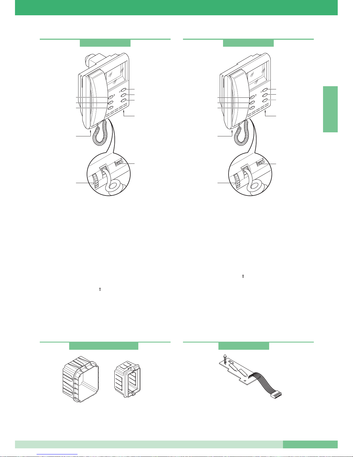
Videocom series semi flush-mounted Monitor (long tube)
Technical characteristics:
Videocom series monitor with dimensions: 193x223x65, flush-mounted
(68mm of depth on wall), white RAL9010
with 4.5” direct vision B/W screen.
Can only be installed on the flush-mounting box Art. 4514 - see
page 27. To be completed with bracket Art. 4714W/2.
The monitor is complete with:
1. Hooks for fixing to the bracket.
2. Brightness control (turn to vary the brightness).
3. Call tone volume control.
(move left to increase the volume).
4. Door-opening push-button
().
5. Push-button to call a switchboard / free contact (1).
6. Push-button self-ignition / video request (2).
7. Push-button actuator * (3).
8. Push-button Privacy * (4).
9. LED * (0).
* only available with optional card Art. 4703W.
Art. 4514 flush-mounted box for monitor Art. 4700W and Art. 4700W/I.
Art. 4517 3 DIN module civil series box usable for flush-mounting
monitor Art. 4700W.
Videocom series surface-mounted Monitor
Technical characteristics:
Videocom series monitor with dimensions: 193x223x65,
surface-mounted, white RAL9010, with 4.5” direct vision B/W
screen. To be completed with bracket Art. 4714W/2.
The monitor is complete with:
1. Hooks for fixing to the bracket.
2. Brightness control (turn to vary the brightness).
3. Call tone volume control.
(move left to increase the volume).
4. Door-opening push-button
().
5. Push-button to call a switchboard / free contact (1).
6. Push-button self-ignition / video request (2).
7. Push-button actuator * (3).
8. Push-button Privacy * (4).
9. LED * (0).
* only available with optional card Art. 4703W
Use of the old Videocom series 4701W monitor may cause operating
problems.
Art. 4700W/I
1
2
4
3
4
5
6
9
1
3
2
1
8
7
Art. 4701W/A
1
2
4
3
4
5
6
1
3
2
1
9
8
7
Art. 4514W and Art. 4517
Additional push-button and LED card
Optional card with 2 additional push-buttons and signalling LED.
To be inserted inside all the Videocom series monitors.
Art. 4703
MT SB2 01
25
MT SB2 01
ENGLISH
Page 27
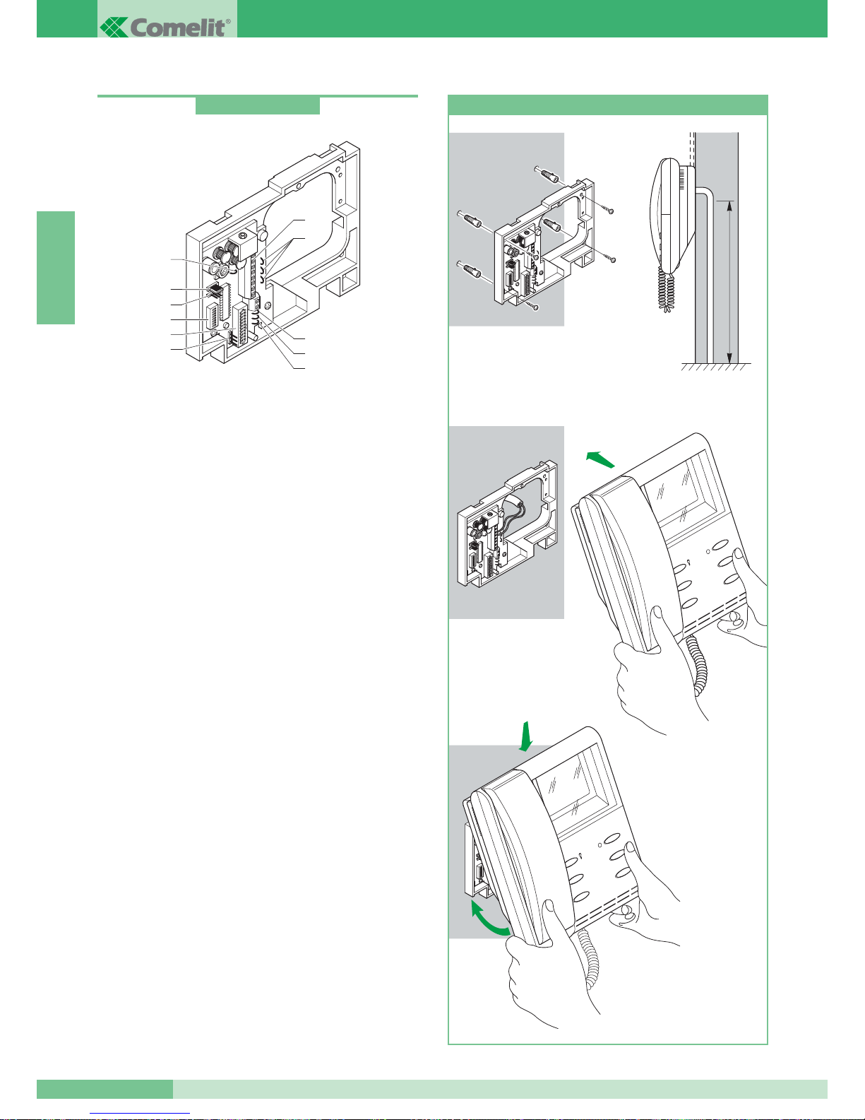
Simplebus2 Bracket
Bracket for fixing the monitor - allows installation of the monitor
to the wall or by means of desk convertion kit Art. 4712W (see
page 27), and permits connection of the system cables.
Provided with terminals for connection of local floor call
(see variant G page 111), for connection of a call repetition device
(see SB2/D on page 105) and for use of push-button 1 of the
monitor for various uses (see variant E on page 110).
Up to 3 brackets with the same user code can be inserted in the
same system (see page 98).
Compatible with Simplebus1 systems.
Technical characteristics
Dimensions: 158x121x24.
1. monitor connector bracket.
2. system connection terminals:
0 +20V connection terminals Art. 1212/B.
L L bus line connection.
CFP CFP local floor call input.
P1 C1 push-button for various uses. To have a clean NO
contact, cut the CV3 and CV4 bridges.
S+ S- terminals for call repeater device.
3. CV5 Bridge for closing video.
4. JP1 jumper for enabling video request
(see variant F on page 110).
5. CN2 connector for programming.
6. Dip switches for programming user code.
7. CV1, CV2, and CV7 additional monitor power supply bridges
by means of Art. 1212/B (see variant SB2/A3 on page 101).
8. CV3, CV4 bridges to free push-button 1.
9. CV6 bridge for selection of type of operation (Simplebus2
or Simplebus1).
10. JP2 jumper selection of type of operation (Simplebus2
or Simplebus1).
Art. 4714W/2
7
1
6
4
5
2
8
9
8
3
10
147
cm
1
2
3
4
1
2
1
2
3
4
Installation of surface-mounted monitor Art. 4701W/A
GROUP S.P.A.
MT SB2 01
26
ENGLISH
Page 28
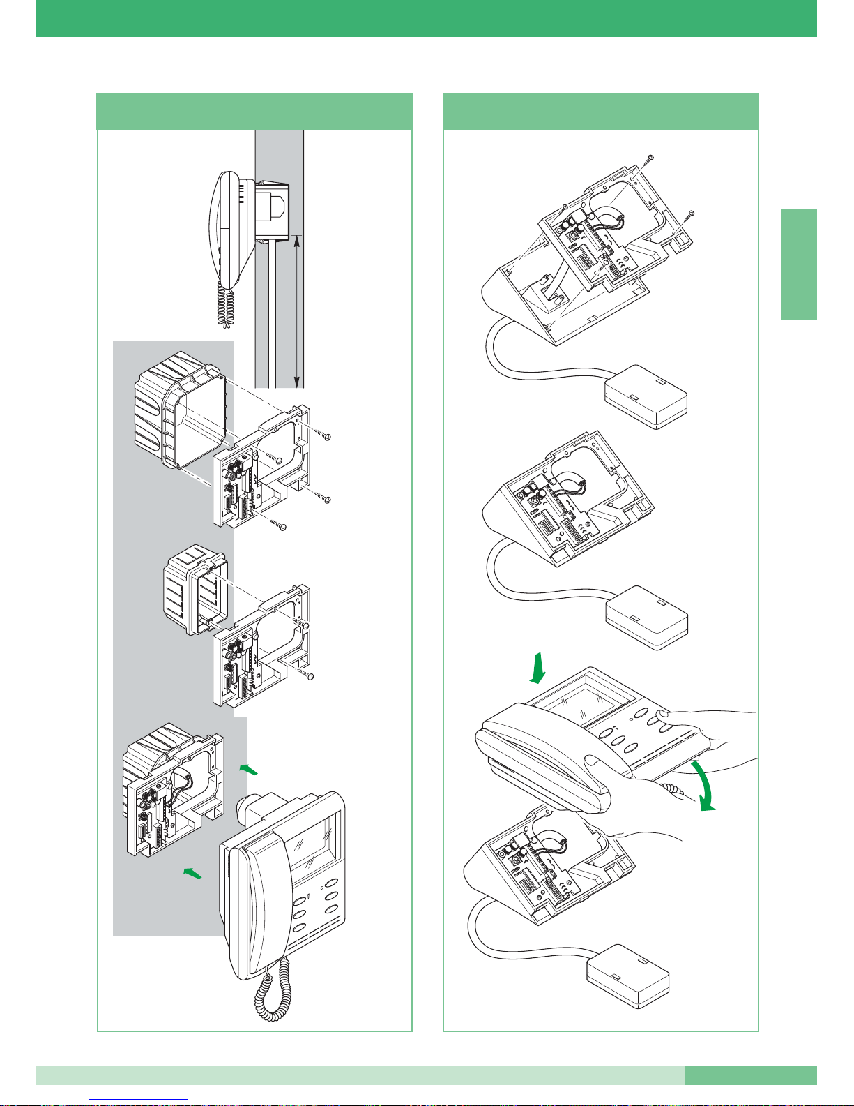
145
cm
1
2
4
3
Art. 4514
Art. 4517
solo per monitor
Art. 4700W
Art.
4700W
4700W/I
Per monitor
Installation of surface-mounted monitor
Art. 4700W and Art. 4700W/I
2
1
4
3
1
2
Installation of desk convertion kit Art. 4712W
for monitor Art. 4701W/A and Art. 4700W
For monitor
Art.
4700W
4700W/I
only for monitor
Art. 4700W
MT SB2 01
27
MT SB2 01
ENGLISH
Page 29
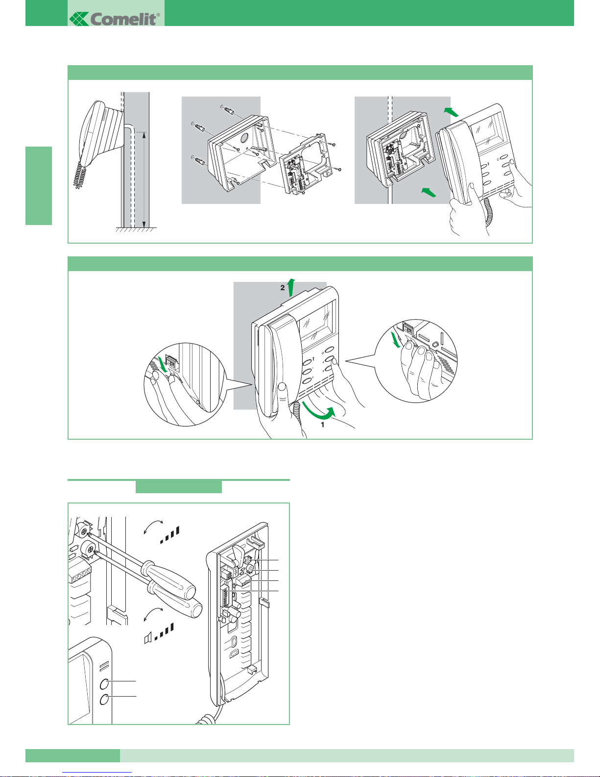
INTERNAL TELEPHONE HANDSETS
Telephone
Okay series telephone with dimensions: 85x223x65 mm.
Fitted with door-opening push-button and with switchboard call pushbutton, usable as push-button for various uses in the systems not
provided with a switchboard (see variant A on page 108). Equipped
as standard with the local floor call function (see variant B on page
108). Up to three telephones with the same user code can be
inserted in the same system. To set the user code, see
“Programming telephone Art. 2408W/A, 2428W and bracket
Art. 4714W/2” on page 40.
Only to be used for audio systems.
Technical characteristics:
1. Door-opening push-button.
2. Switchboard call push-button/push-button for various uses present
in terminal board (AB).
3. Terminal connection System with
L L connection to the line bus.
CFP CFP input floor door call.
AB push-button normally dedicated to various services.
To have a clean NO contact, cut bridges CV1 and CV2.
4. Dip switches for setting user code (see page 40).
5. Microphone volume adjustment trimmer.
6. Call tone volume adjustment trimmer.
147 cm
Art. 4704
1
2
4
3
Art. 4700W
1
2
+
-
+
-
MIC
5
6
3
4
Installation of semi flush-mounted monitor Art. 4700W with surface-mounting adapter Art. 4704
How to remove the monitor
Art. 2408W/A
GROUP S.P.A.
MT SB2 01
28
ENGLISH
Page 30
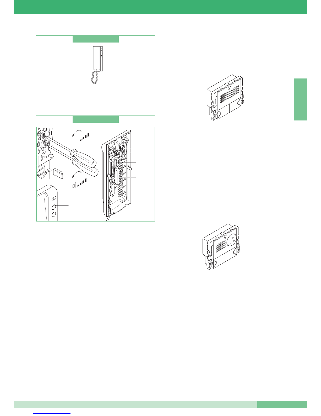
Telephone
Telephone like Art. 2408W/A with additional switch and LED
Privacy or Doctor facility (automatic lock opening following
the call). See the technical sheet inside the article for the
connection to the system.
Telephone
Telephone in the OKAY line with dimensions: 85x223x65 mm.
Fitted with door-opening push-button and switchboard call
push-button, to be used for various purposes in the systems not
provided with a switchboard (see variant C on page 109).
Equipped as standard with local floor call function (see variant D on
page 109) and call repetition (see SB2/D on page 105). Telephone
to be used in mixed audio-video systems upstream of Art. 4896 or
in audio systems when the call repeat function is required. Up to
three telephones with the same user code can be inserted in the
same system. For methods of inserting additional telephones with
the same user code, see variants SB2/A4 and SB2/A5 on page 102.
To set user code, see “Programming telephone Art. 2408W/A,
2428W and bracket Art. 4714W/2” on page 40.
Technical characteristics:
1. Door-opening push-button.
2. Switchboard call push-button/push-button for various uses
present in the terminal board (P1 C1).
3. Terminal connection System with
L L connection to the line bus.
CFP CFP local floor call input.
P1 C1 push-button normally dedicated to various services.
To have a clean NO contact, cut bridges CV2 and CV3.
S+ S- terminals to connect a bell repetition device to.
4. Dip switches for setting user code (see page 40).
5. Microphone volume adjustment trimmer.
6. Call tone volume adjustment trimmer.
EXTERNAL UNITS
In Simplebus2 systems, external units of the Powercom,
Vandalcom and Logicom Series can be used. For Vandalcom and
Logicom, refer to technical sheet FT/SB/01 and to Catalogue 50.
Powercom Series speaker unit
Consisting of Art. 3320 + Art. 1602.
Speaker unit with terminal board and double amplifier, watertight
loudspeaker and electret microphone.
Microphone and loudspeaker volume adjustable from the front
on Art.1602 (see page 32); possibility of rear adjustment as well
in the case where it is mounted on Art. 3320.
The microphone can be removed to improve the acoustic output
(see page 32). Aluminium alloy call button with name label
extractable from the front. Complete with microprocessor and Dip
switches with 8 positions for programming the calls to the users.
For push-button programming, see page 42. 12V AC power supply
(use Art. 1195). Door-opening function by means of an electric
switch (3A only AC).
Dimensions: 112x89.5x40 mm.
Powercom Series video speaker unit
Consisting of Art. 3321 + Art. 4660.
1/4” pin-hole CCD B/W high sensitivity adjustable camera.
Infrared illumination (6 LEDs) .
Complete with terminal board and speaker unit with double
amplifier, watertight loudspeaker and electret microphone.
Microphone and loudspeaker volume adjustable from the front
on Art.4660 (see page 32). Possibility of rear adjustment as well
in the case where it is mounted on Art. 3321.
The microphone can be removed to improve the acoustic output
(see page 32). Aluminium alloy call button with name label
extractable from the front.
Complete with microprocessor and Dip switches with 8 positions
for programming the calls to the users. For push-button
programming, see page 42. 12V AC power supply (use Art. 1195).
Door-opening function by means of electronic switch on board
(3A only alternating).
Dimensions: 112x89.5x40 mm.
5
6
1
2
4
3
+
-
+
-
MIC
Art. 2410W
Art. 2428W
MT SB2 01
29
MT SB2 01
ENGLISH
Page 31
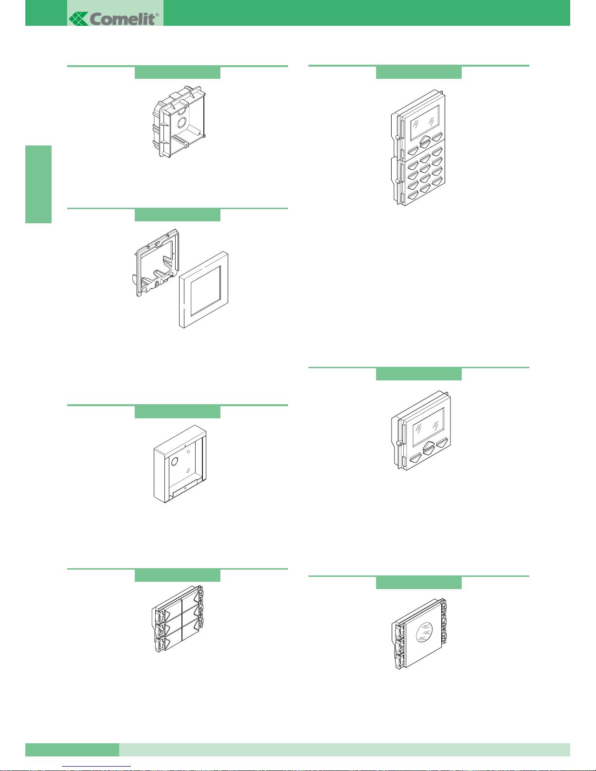
Flush-mounting boxes
Available for 1, 2 and 3 modules.
Single module dimensions: 127x127x45 mm.
Module holder frames complete with cornice
Made of die-cast aluminium and painted using special coatings to
resist at outdoor environments.
Available for 1, 2 and 3 modules in the Grey, White, Blue and Orange.
Single module dimensions: 125x125x15.5 mm.
Surface-mounted housings
Stainless steel housing. Available for 1, 2, 3, 4, 6 and 9 modules.
Surface-mounted. Useful when it is not possible to flush-mount the
box. Single module dimensions: 123x123x32.5 mm.
System engaged signalling module
Complete with flashing blue LED for visual indication of the
engaged state. The transparent label is provided blanck to insert
the correct wording. Dimensions: 112x89.5x38 mm.
Digital call module complete with electronic directory
Complete with graphic LCD 128x64 dots, keypad with 16
push-buttons illuminated from the rear with blue LED.
Also operates with electronic code key with the possibility of
entering up to 250 passwords. It is complete with electronic name
directory, which memorises 400 user names. Name scrolling is
carried by using two search push-buttons or by entering the initials
of the name or user code directly. Once the desired user name is
displayed, simply press the call push-button. User programming is
carried out in a simple way using programmer art. 1230 or with the
software for PC art. 1249
Dimensions: 112x180x40 mm.
Electronic directory module
Electronic name directory, with graphic display 128x64 dots.
Memorises 400 user names. Name scrolling is carried out by using
two search push-buttons. Once the desired user name is displayed,
simply press the call push-button. User programming is carried out
in a simple way using programmer art. 1230 or with the software for
PC art. 1249. Dimensions: 112x89.5x40 mm.
Call push-button modules
Call push-button module fitted with micro-switch and made of diecast and chromed aluminium alloy. Blue LEDs for illumination of
the nameplate labels removable from the front. Available with 4 and
6 push-buttons. Dimensions: 112x89.5x40 mm. For push-button
programming, see page 42.
Art. 3110
Art. 3323
Art. 3342
Art. 3346
Art. 3340
Art. 3311
Art. 3316
GROUP S.P.A.
MT SB2 01
30
ENGLISH
Page 32
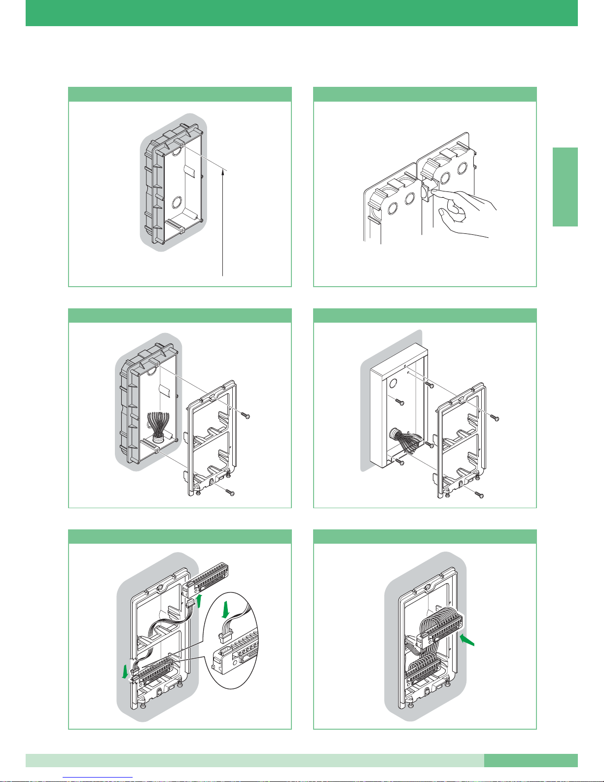
Instructions for installing external audio and video unit
160 - 165 cm
Height of flush-mounted box How to place several boxes together
Fixing the frame onto the flush-mounting box
Fixing the frame onto the surface-mounted housing
Connection of 4-pole cable Cabling terminal board inserted or withdrawn
MT SB2 01
31
MT SB2 01
ENGLISH
Page 33
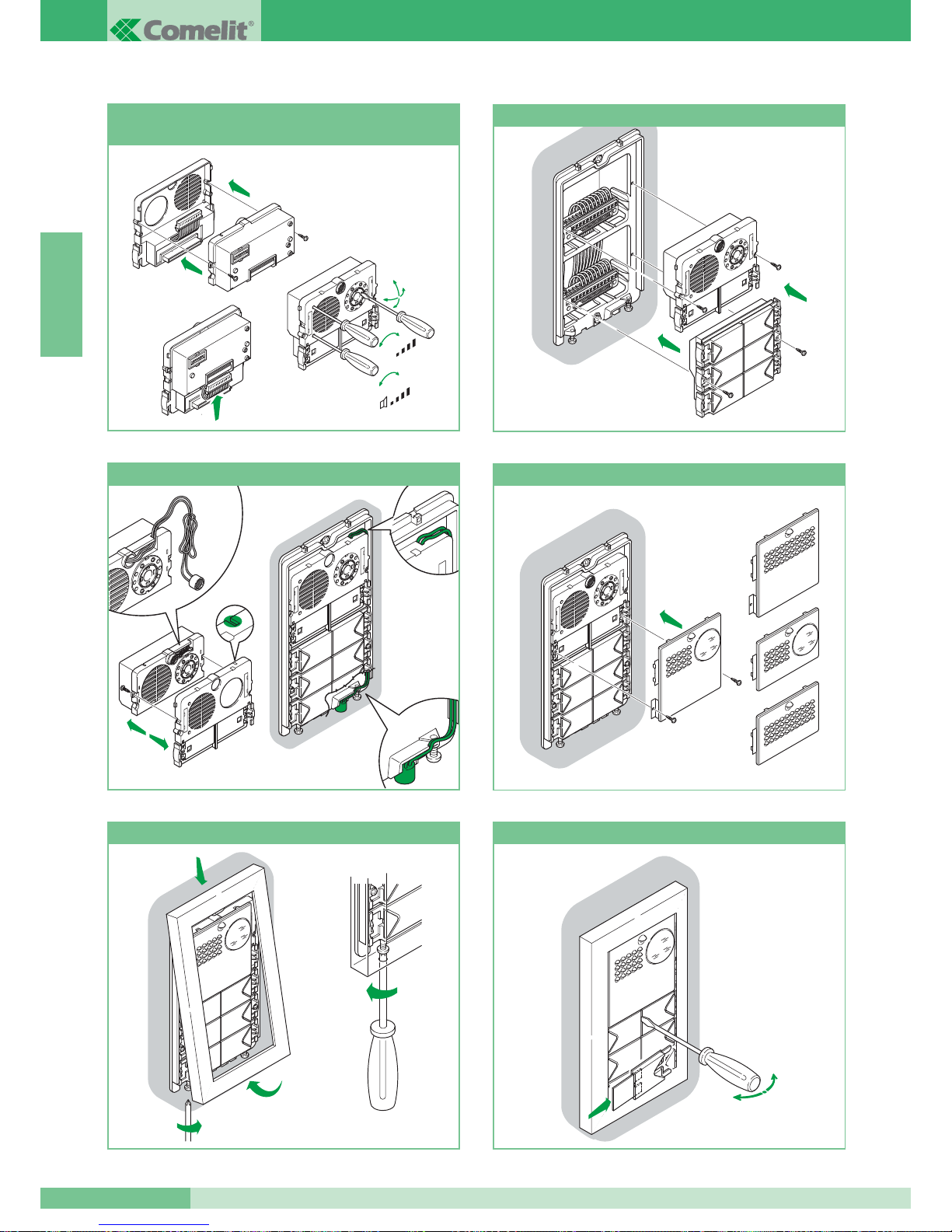
1
2
3
360˚
+
-
+
-
MIC
Audio-video Group Assembly,
connections and adjustments
Insertion of modules
2
3
5
1
4
Alternative position of the microphone
Assembly/Dismantling faces
Fixing the cornice
C
arla
R
ossi
Assembly /Dismantling labels
open
close
GROUP S.P.A.
MT SB2 01
32
ENGLISH
Page 34
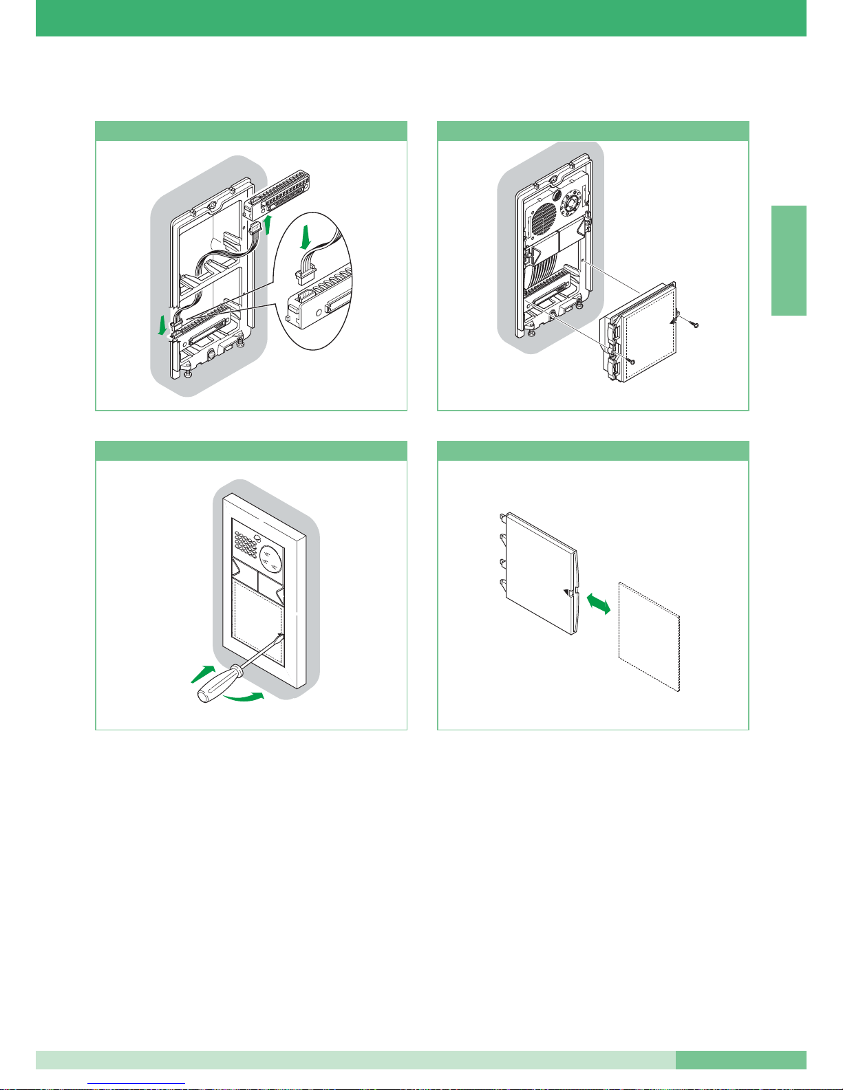
Connection of 4-pole cable
10
Insertion of module
2
1
10
Withdrawal of label holder
15
Insertion/withdrawal of label
Instructions for assembly of information modules Art. 3326, Ar t. 3344 and Ar t. 3346
MT SB2 01
33
MT SB2 01
ENGLISH
Page 35
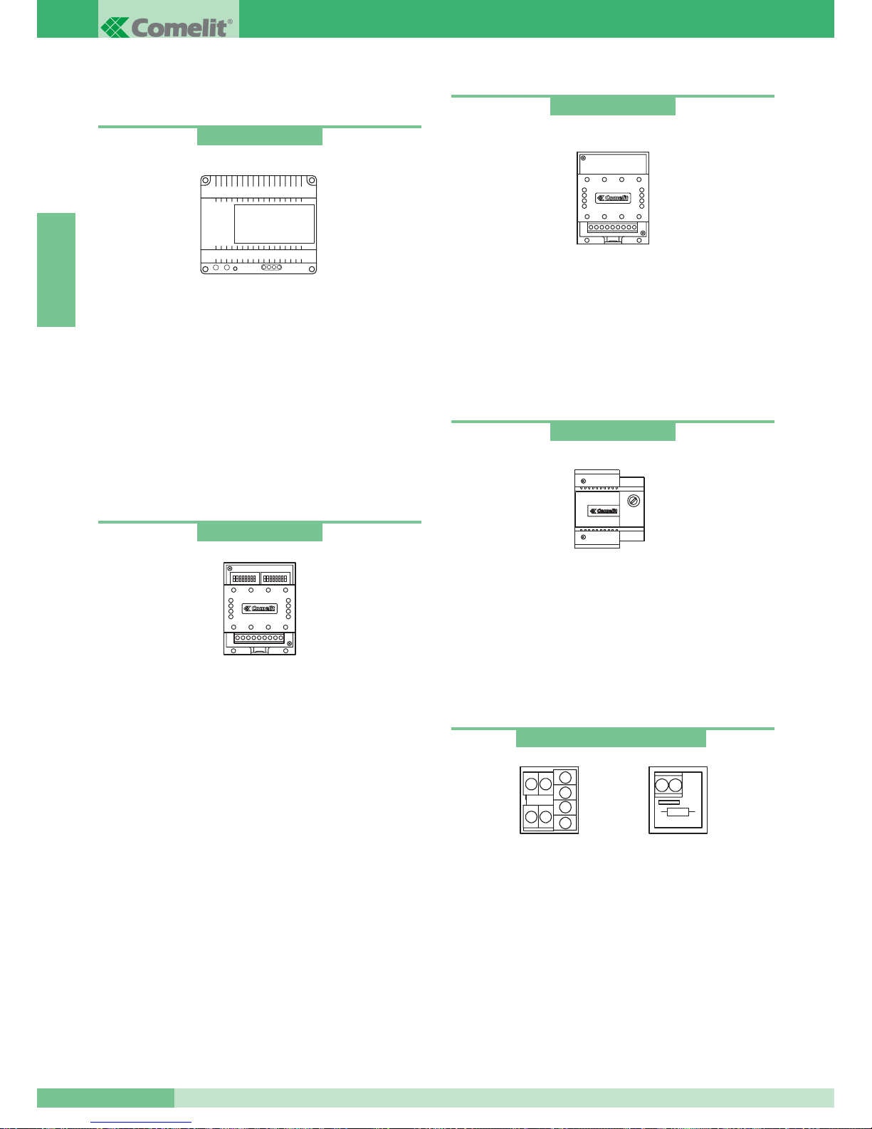
POWER SUPPLIES AND ACCESSORIES
Transformer for Mixer-power supply
65VA Transformer. (T 1 min. on / 5 min. off).
Primary: 230VAC
Secondary: OUT1: 36VAC 1.5A
OUT2: 14VAC 1A
The transformer is equipped with internal protection PTC.
Dimensions: 107x90x60 (8 DIN modules).
Switching device
Power supply 12VAC-20VDC.
Dimensions: 66x85x35mm (4 DIN modules).
Terminals for system connection:
~ ~ * 12VAC-20VDC power supply.
LS LS secondary external unit bus line input.
LP LP main external unit bus line input.
LM LM riser bus line output.
For programming switching device, see page 40.
Power supply for additional monitor
Power supply 15VA (interm.).
Input: 230VAC
Output: 0- 20VDC 700mA
The transformer is equipped with internal protection PTC.
Dimensions: 87x105x65 (5 DIN modules).
Art. 1246
Line branch and termination terminal
See page 42 for configuration of Art. 1216 according to the
cable used.
Terminals for system connection:
Lin Lin: riser line input.
Lout Lout: riser line output.
LM LM: riser line branched towards the monitor/telephone.
+ +: power supply connection terminals for compatibility
with Simplebus1 systems.
Art. 1212/B
Relay
12-24V DC-AC 5A relay for general uses. Can be controlled directly
from the call repetition output of bracket Art. 4714W/2 or telephones
Art. 2428W. Dimensions: 66x85x35 mm (4 DIN modules).
Terminals for system connection:
+ - power supply relay.
C-NO-NC relay contacts.
Art. 1122/A
Art. 1214/2 and Art. 1216
Art. 1214/2
Art. 1216
Art. 1224
GROUP S.P.A.
MT SB2 01
34
ENGLISH
Page 36
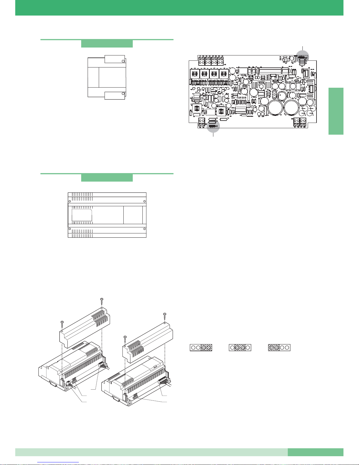
Transformer
Transformer 60VA (interm).
Primary 230VAC
Secondary: OUT1: 0-12V 1.5A
OUT2: 0-12V 1.5A
The transformer is equipped with internal protection fuse.
Dimensions: 87x105x65 (5 DIN modules).
Mixer-power supply
The Mixer-power supply Art. 4896 is contained in a 12 DIN module
box. Dimensions: 208x140x65 mm.
To access the connection terminals, remove the side covers as
shown in the figure.
Art. 4896
Art. 1195
4
1
3
4
2
JP1
JP2
Art. 4896 must be supplied by means of transformer Art.1246.
Carry out the cabling and system connection prior to the
connection of the power supply operations after disconnecting
the mains supply. This unit is fitted with a protection PTC, device
after a short-circuit, d0sconnect the power supply for approximately
one minute to allow re-setting. Insert the line on input from the
external unit, and then switch on the power from Art. 1246 to the
Mixer-power supply module Art. 4896.
The device allows a maximum of one monitor to be supplied
and is able to manage a
MAX of 100 users.
Terminals for system connection:
1.
Lin Lin connection to the line coming from the external unit.
2. 0V 36V connection to terminals OUT1 of transformer Art. 1246.
0V 14V connection to terminals OUT2 of transformer Art. 1246.
3. L1 L1 branch output 1 of riser.
L2 L2 branch output 2 of riser.
L3 L3 branch output 3 of riser.
L4 L4 branch output 4 of riser.
4. Jumpers to be set according to the number of total users
connected to the Mixer-power supply Art. 4896.
JP1 and JP2 in
position 3 for systems with from 0 to 15 users.
JP1 and JP2 in position 2 for systems with from 16 to 35 users.
JP1 and JP2 in position 1 for systems with from 36 to 100 users.
JP1 - JP2
2
3
1
MT SB2 01
35
MT SB2 01
ENGLISH
Page 37
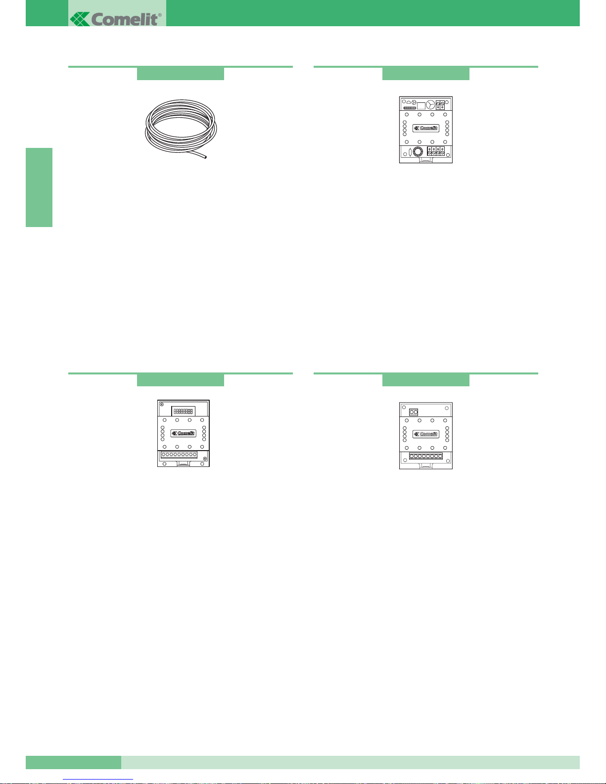
Line amplifier
Amplifier for Simplebus video systems.
This regenerates the riser signal in relation to the video component.
Power supply: 12V AC or 20V DC.
Only to be mounted on the input stretch of the system to the
Mixers-power supplies Art. 4896.
Dimensions: 66x85x35 mm (4 DIN modules).
Terminals for system connection:
Lin Lin: riser line input.
Lout Lout: riser line output.
~+ ~-: power supply module.
Art. 4833/A
Line concentrator
Line concentrator for Simplebus video system.
Allows distribution of the signal over 4 risers.
Only to be mounted on the input stretch of the system to the
Mixers-power supplies Art. 4896.
Dimensions: 66x85x35 mm (4 DIN modules).
Terminals for system connection:
Lin Lin: riser line input.
L1 L1: branch output1 of riser.
L2 L2: branch output2 of riser.
L3 L3: branch output3 of riser
(cut the resistance before inserting the cables).
L4 L4: branch output4 of riser
(cut the resistance before inserting the cables).
Art. 4834/2
Simplebus2 Comelit Cable
Specific cable for Simplebus 2 systems: consists of two twisted
red and black conductors with 1mm
2
cross-section.
Available in 100 and 500 m. coils.
Relay for various services
Power supply 12VAC, 20VDC.
Relay capacity: 10A.
This accessory allows:
• bell repetition service.
• Relay control service from internal unit in systems without
switchboard.
• stair lights service.
• secondary door-opening service.
For cabling and explanation of services, please see the Art. 1254
documentation.
Art. 4577
Art. 1254
GROUP S.P.A.
MT SB2 01
36
ENGLISH
Page 38
INSTALLATION RULES
Installation rules for video door entry systems
Avoid placing the riser wires near power supply cables (220/380V).
In the branches towards each user, insert terminal Art. 1214/2
supplied to equip the bracket Art. 4714W/2 or which can be
purchased separately for the telephones Art. 2428W on the riser.
Terminate each riser or branch with Art. 1216 supplied with the
Mixer-power supply Art. 4896 and with the video module Art. 4660.
According to the cable used for the riser, set closure on Art. 1216
as shown in the table on page 42.
According to the cable used for the riser, assess the maximum
distance which can be reached between the Mixer-Power supply
Art.4896 and the monitor furthest away, and between terminal of
branch terminal Art. 1214/2 and the monitor furthest away.
According to the cable used for the connection, assess the
maximum distance which can be reached between the external unit
video and the Mixer-power supply Art. 4896.
Refer to the tables on page 38 to assess the distances according
to the conductors.
Each Art.4896 can manage a
MAX of 4 riser branches - see
variant SB2/B on page 103.
In the case of systems with main and secondary entrances
(see diagram SB2V/EN/112 on page 97), it is necessary to use the
line concentrator Art. 4834/2 and the switching device Art. 1224.
In the case of a single entrance, it is possible to connect
up to 4
Mixers-power supplies Art. 4896 after Art. 4834/2 (see diagram
SB2V/012 on page 94).
Each Art. 4834/2 allows a
MAX of 4 branches: in the case where
several branches are needed (up to 16), it is necessary to put two
Arts. 4834/2 in cascade. The additional Art. 4834/2 must be
preceded by the relative video signal amplifier Art. 4833/A
(see variant SB2/C on page 104). A
MAX of 2 Arts. 4834/2 in
cascade can be inserted.
The
MAX number of users which can be connected to a single
Mixer-power supply Art. 4896 is 100
regardless of whether they
are divided over a single riser or over several riser branches
(e.g.: 100 users over a single riser or 25 users over each of the
4 riser branches.)
It is possible to connect
up to 25 monitors in cascade for each riser
branch (see variant SB2/G on page 106). In this case, in order
to determine the Max. distance between external unit and the last
monitor of the cascade, please refer to the table on page 38
column
A.
The connection between several monitors with same user code
(
MAX 3) can take place in cascade or branched from the riser
following the variants SB2/A1-A2-A3-A4-A5 (pages 99-100-101-102).
Telephones Art. 2428W with same monitor user code must be
branched directly from the riser by means of Art. 1214/2.
Art. 4896 supplies
only a single monitor for each call, therefore
for systems with several monitors with the same user code, it is
necessary to set the additional monitors as secondary or supply
each additional monitor with power separately by means of
Art.1212/B (see pages 99-100-101).
Set the bridges and the jumper on bracket Art. 4714W/2 as shown
in the variants to the basic diagrams SB2/A1-A2-A3 according to
the configuration to be obtained.
The cameras of the external units must not be directed towards
direct light sources (e.g.. lamps, sunlight, reflecting surfaces, etc.).
MT SB2 01
37
MT SB2 01
ENGLISH
Page 39
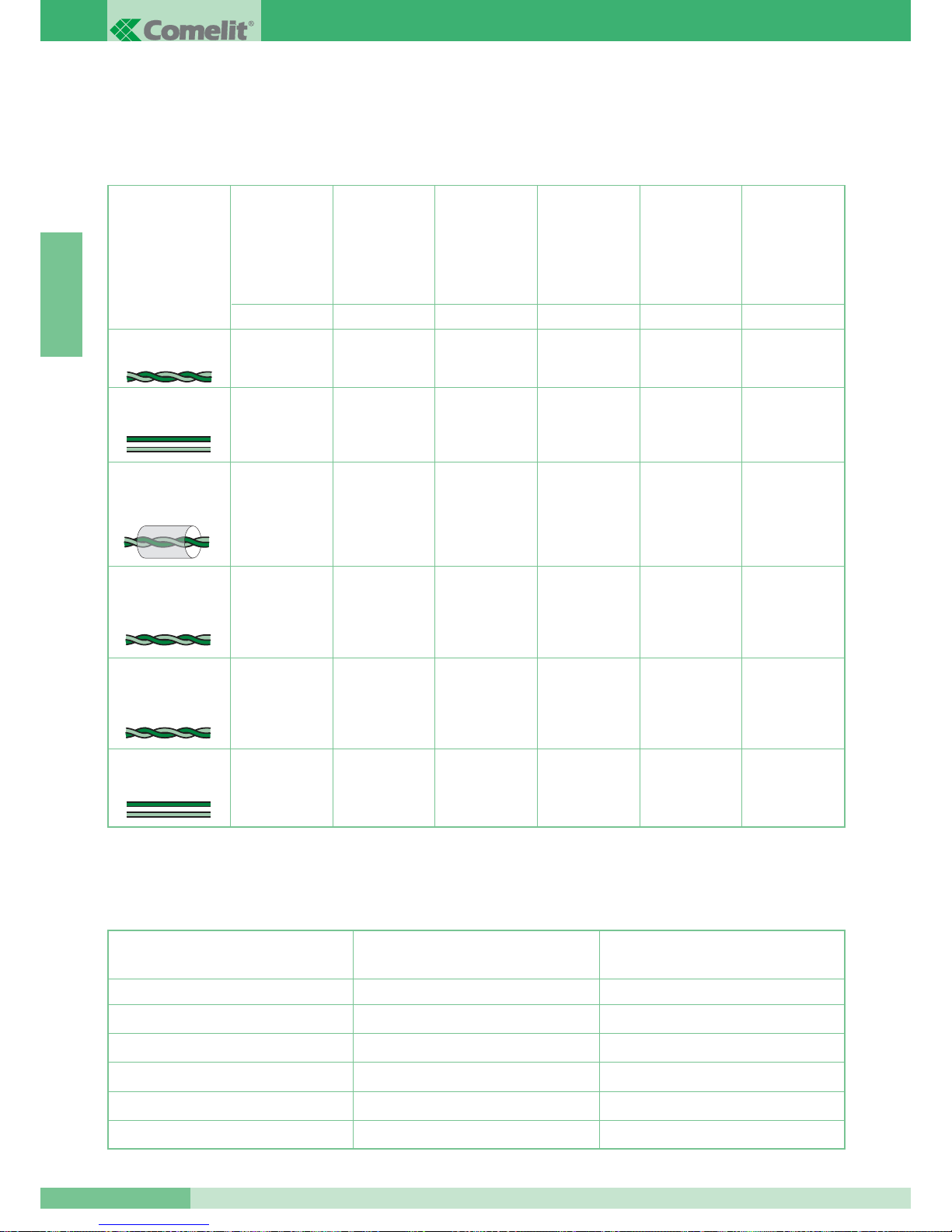
Maximum distances and characteristics of the conductors
The connection of the apparatus is of the unpolarised type.
The use of conductors with characteristics other than those prescribed does not guarantee certain system distances being reached or the
good quality of the video signal, therefore only use the cables described in the tables below.
Maximum distances which can be reached by the conductors off additional monitor power supply and external unit power supply
Type of cable
Twisted telephone cable
0.28 mm
2
cross-sect.
(Ø 0.6 mm)
*
UTP5 cat 5 AWG 24
Cable 0.2 mm2crosssect. (Ø 0.5 mm)
*
200 m
150 m
120 m
100 m
200 m
100 m
80 m
150 m
200 m
100 m
80 m
150 m
200 m
100 m
80 m
150 m
150 m
80 m
50 m
100 m
ABCDE
Max. distance
between Mixer
Art. 4896 and
internal unit.
Max. distance
between external
unit and Mixer
Art. 4896
Max. distance
between external
unit and
Art. 4833/A.
Max. distance
between Art.
4833/A and Mixer
Art. 4896.
Max. distance
between external
unit and Mixer or
amplifier Art. 4833/A
with a Art. 4834/2
inserted.
60 m
40 m
30 m
40 m
80 m 150 m 150 m 150 m 100 m 40 m
H
Max. distance
between terminal
of branch
Art. 1214/2 and
internal unit.
Comelit cable Art. 4577
1 mm2cross-sect. (Ø 1.2 mm)
Two-wire cable 1.5 mm
2
cross-sect. (Ø 1.4 mm)**
Braided and shielded
cable 1 mm2cross-sect.
(Ø 1.2 mm)
*
Cross-section of the conductor
4 m
10 m
20 m
30 m
40 m
10 m
25 m
50 m
100 m
150 m
FG
Max. distance between transformer
Art. 1195 and external unit.
Max. distance between power supply
Art. 1212/B and internal unit.
0.28 mm
2
(Ø0.6 mm)
0.5 mm
2
(Ø0.8 mm)
1 mm
2
(Ø1.2 mm)
1.5 mm
2
(Ø1.4 mm)
2 mm
2
(Ø1.6 mm)
Two-wire cable 0.5 mm
2
cross-sect. (Ø 0.8 mm)
**
120 m 100 m 100 m 100 m 80 m 40 m
* In case of multipaired cable, it is advisable to use one pair only for the system. If necessary to reduce voltage drop, due to long distances,
it is possible to use a pair as a single core.
** In case of multicore cable, it is necessary to use only two of the available wires. We recommend not to double up on the conductors.
GROUP S.P.A.
MT SB2 01
38
ENGLISH
Page 40
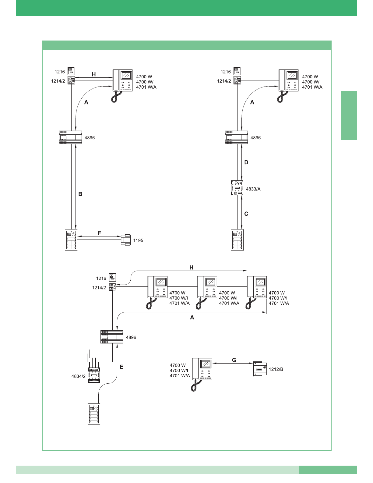
Figures showing distances
MT SB2 01
39
MT SB2 01
ENGLISH
Page 41
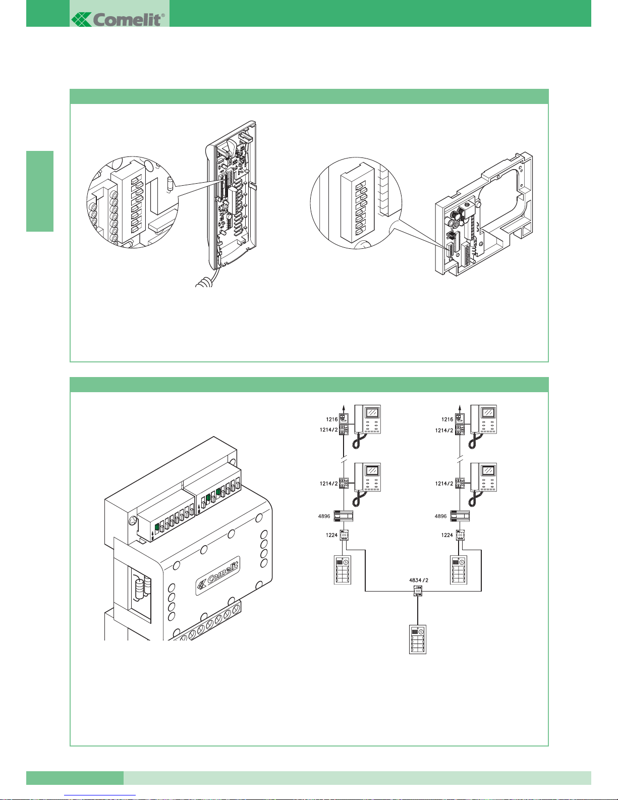
ENGLISH
CONFIGURATION OF THE DEVICES
Programming telephone Art. 2408W/A, 2410W, 2428W and bracket Art. 4714W/2
• Each telephone or bracket in the system is identified
by means of its own code. This code must be set by means
of the Dip switches on the telephone card or on the bracket
(see figures).
• The user code must be set according to the corresponding one
described in the programming table on page 41.
• Coding can take place at any time, even without a power
supply.
1 2
3
4 5
6 7
8
1 2
3
4 5
6 7
8
Programming switching device Art. 1224
• Each switching device module is fitted with a pair of Dip
switches with 8 selectors (see figure). The two Dip switches
define the minimum and maximum range - MIN - MAX - of
codes which can be recognised by the switching device.
•
Remember that the MIN and MAX Dip switches define the lowest and
highest user codes respectively which can be connected to the riser.
• For setting the values desired, refer to the table on page 41.
• Distinct switching devices must manage code ranges which are
not overlapping.
PORTA PRINCIPALE DAL N° 1÷20.
SCALA A SCALA B
4700 W
4700 W/I
4701 W/A
4700 W
4700 W/I
4701 W/A
N° 1÷10 N° 11÷20
4700 W
4700 W/I
4701 W/A
4700 W
4700 W/I
4701 W/A
MAX
MIN
1
2
3
4
5
6
7
8
1
2
3
4
5
6
7
8
O
N
O
N
• Example of coding switching device Art. 1224 of staircase A
minimum number: 1, maximum number: 10.
GROUP S.P.A.
MT SB2 01
40
STAIRCASE A
N° 1÷10.
MAIN ENTRANCE FROM N° 1÷20.
STAIRCASE B
N° 11÷20.
Page 42
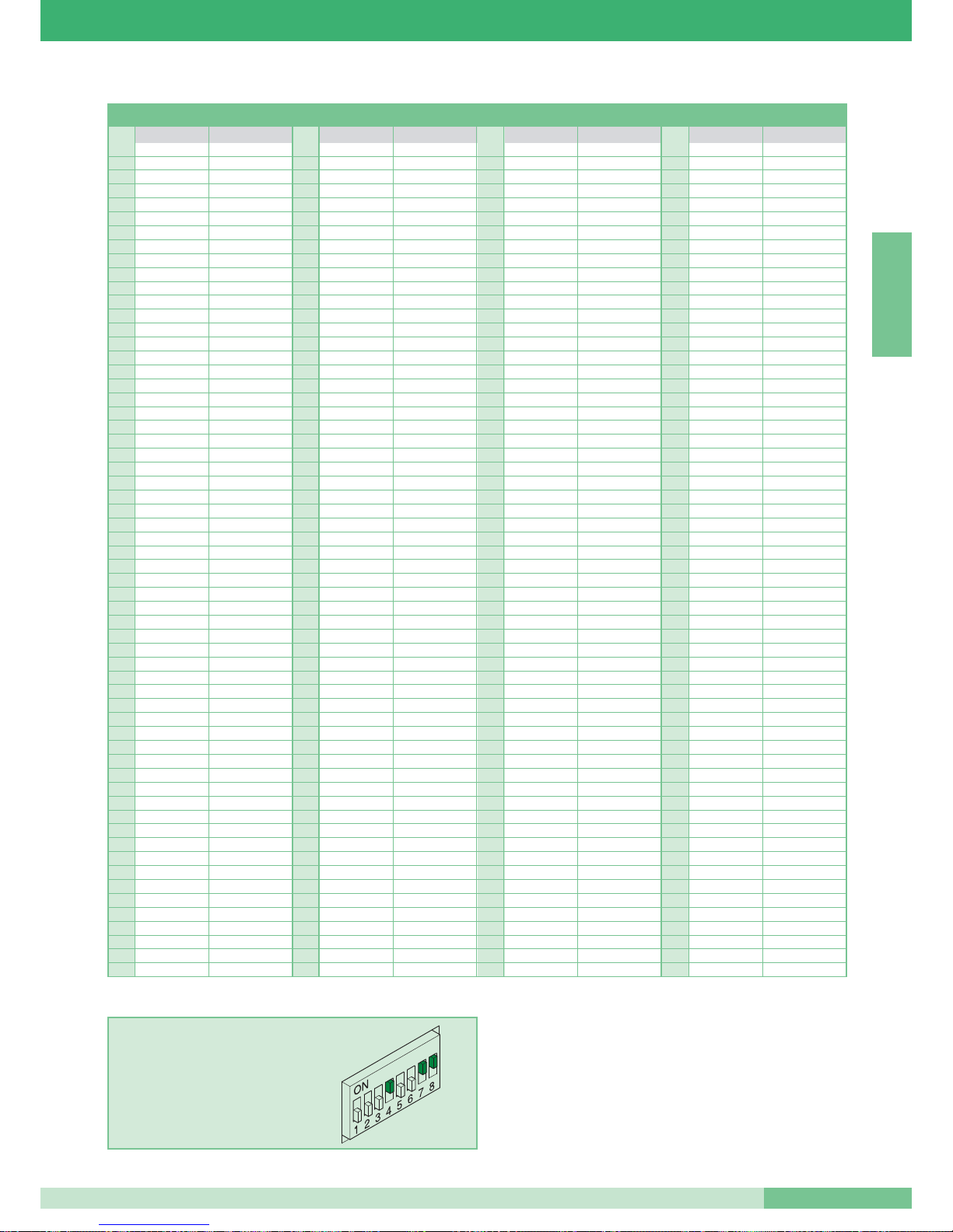
ENGLISH
Table for programming the Dip switches
11 61 1,3,4,5,6 121 1,4,5,6,7 181 1,3,5,6,8
22 62 2,3,4,5,6 122 2,4,5,6,7 182 2,3,5,6,8
3 1,2 63 1,2,3,4,5,6 123 1,2,4,5,6,7 183 1,2,3,5,6,8
43 64 7 124 3,4,5,6,7 184 4,5,6,8
5 1,3 65 1,7 125 1,3,4,5,6,7 185 1,4,5,6,8
6 2,3 66 2,7 126 2,3,4,5,6,7 186 2,4,5,6,8
71,2,3 67 1,2,7 127 1,2,3,4,5,6,7 187 1,2,4,5,6,8
84 68 3,7 128 8 188 3,4,5,6,8
9 1,4 69 1,3,7 129 1,8 189 1,3,4,5,6,8
10 2,4 70 2,3,7 130 2,8 190 2,3,4,5,6,8
11 1,2,4 71 1,2,3,7 131 1,2,8 191 1,2,3,4,5,6,8
12 3,4 72 4,7 132 3,8 192 7,8
13 1,3,4 73 1,4,7 133 1,3,8 193 1,7,8
14 2,3,4 74 2,4,7 134 2,3,8 194 2,7,8
15 1,2,3,4 75 1,2,4,7 135 1,2,3,8 195 1,2,7,8
16 5 76 3,4,7 136 4,8 196 3,7,8
17 1,5 77 1,3,4,7 137 1,4,8 197 1,3,7,8
18 2,5 78 2,3,4,7 138 2,4,8 198 2,3,7,8
19 1,2,5 79 1,2,3,4,7 139 1,2,4,8 199 1,2,3,7,8
20 3,5 80 5,7 140 3,4,8 200 4,7,8
21 1,3,5 81 1,5,7 141 1,3,4,8 201 1,4,7,8
22 2,3,5 82 2,5,7 142 2,3,4,8 202 2,4,7,8
23 1,2,3,5 83 1,2,5,7 143 1,2,3,4,8 203 1,2,4,7,8
24 4,5 84 3,5,7 144 5,8 204 3,4,7,8
25 1,4,5 85 1,3,5,7 145 1,5,8 205 1,3,4,7,8
26 2,4,5 86 2,3,5,7 146 2,5,8 206 2,3,4,7,8
27 1,2,4,5 87 1,2,3,5,7 147 1,2,5,8 207 1,2,3,4,7,8
28 3,4,5 88 4,5,7 148 3,5,8 208 5,7,8
29 1,3,4,5 89 1,4,5,7 149 1,3,5,8 209 1,5,7,8
30 2,3,4,5 90 2,4,5,7 150 2,3,5,8 210 2,5,7,8
31 1,2,3,4,5 91 1,2,4,5,7 151 1,2,3,5,8 211 1,2,5,7,8
32 6 92 3,4,5,7 152 4,5,8 212 3,5,7,8
33 1,6 93 1,3,4,5,7 153 1,4,5,8 213 1,3,5,7,8
34 2,6 94 2,3,4,5,7 154 2,4,5,8 214 2,3,5,7,8
35 1,2,6 95 1,2,3,4,5,7 155 1,2,4,5,8 215 1,2,3,5,7,8
36 3,6 96 6,7 156 3,4,5,8 216 4,5,7,8
37 1,3,6 97 1,6,7 157 1,3,4,5,8 217 1,4,5,7,8
38 2,3,6 98 2,6,7 158 2,3,4,5,8 218 2,4,5,7,8
39 1,2,3,6 99 1,2,6,7 159 1,2,3,4,5,8 219 1,2,4,5,7,8
40 4,6 100 3,6,7 160 6,8 220 3,4,5,7,8
41 1,4,6 101 1,3,6,7 161 1,6,8 221 1,3,4,5,7,8
42 2,4,6 102 2,3,6,7 162 2,6,8 222 2,3,4,5,7,8
43 1,2,4,6 103 1,2,3,6,7 163 1,2,6,8 223 1,2,3,4,5,7,8
44 3,4,6 104 4,6,7 164 3,6,8 224 6,7,8
45 1,3,4,6 105 1,4,6,7 165 1,3,6,8 225 1,6,7,8
46 2,3,4,6 106 2,4,6,7 166 2,3,6,8 226 2,6,7,8
47 1,2,3,4,6 107 1,2,4,6,7 167 1,2,3,6,8 227 1,2,6,7,8
48 5,6 108 3,4,6,7 168 4,6,8 228 3,6,7,8
49 1,5,6 109 1,3,4,6,7 169 1,4,6,8 229 1,3,6,7,8
50 2,5,6 110 2,3,4,6,7 170 2,4,6,8 230 2,3,6,7,8
51 1,2,5,6 111 1,2,3,4,6,7 171 1,2,4,6,8 231 1,2,3,6,7,8
52 3,5,6 112 5,6,7 172 3,4,6,8 232 4,6,7,8
53 1,3,5,6 113 1,5,6,7 173 1,3,4,6,8 233 1,4,6,7,8
54 2,3,5,6 114 2,5,6,7 174 2,3,4,6,8 234 2,4,6,7,8
55 1,2,3,5,6 115 1,2,5,6,7 175 1,2,3,4,6,8 235 1,2,4,6,7,8
56 4,5,6 116 3,5,6,7 176 5,6,8 236 3,4,6,7,8
57 1,4,5,6 117 1,3,5,6,7 177 1,5,6,8 237 1,3,4,6,7,8
58 2,4,5,6 118 2,3,5,6,7 178 2,5,6,8 238 2,3,4,6,7,8
59 1,2,4,5,6 119 1,2,3,5,6,7 179 1,2,5,6,8 239 1,2,3,4,6,7,8
60 3,4,5,6 120 4,5,6,7 180 3,5,6,8
*240 5,6,7,8
*NOTE: code 240 is reserved for the switchboard.
EXAMPLE: setting code 200.
User code
Dip switches to ON User name
User code
Dip switches to ON User name
User code
Dip switches to ON User name
User code
Dip switches to ON User name
MT SB2 01
41
MT SB2 01
Page 43
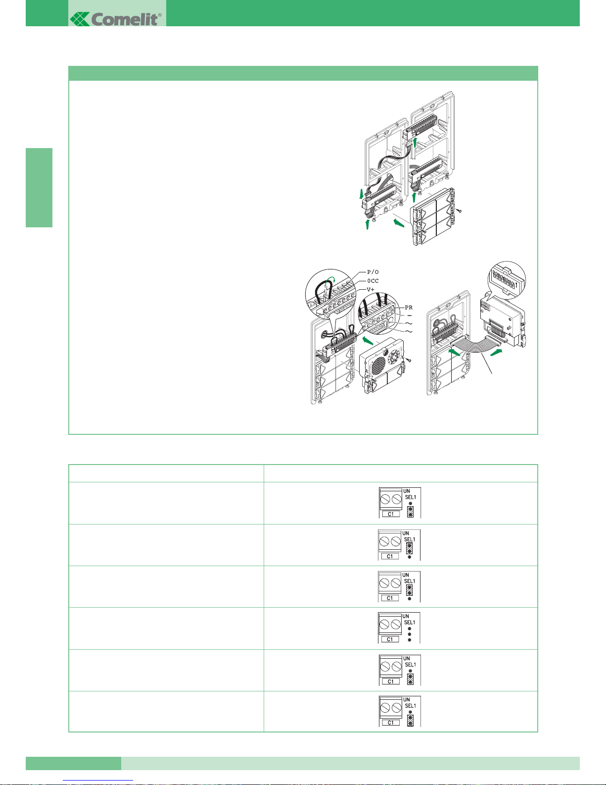
ENGLISH
Push-button programming with audio Art. 1602 and video Art.4660 group and modules Art. 3323/4 and 3323/6
1. Connect the terminal boards of modules Art. 3323/4 and
Art. 3323/6 together and with the terminal board of the
Art. 4660 or Art. 1602 group using the special cables. Insert the
modules Art. 3323/4 and Art. 3323/6 on the relative terminal
boards (figure 1).
2. On the terminal board of module Art. 4660 or Art. 1602 connect
the power supply to ~~ , connect PR to -- and move P/O from
OCC to V+ (figure 2) using the jumpers present on the terminal
board itself. Connect the terminal board to module Art. 4660 or
Art. 1602 assembled as shown previously. (Warning - modules
Art. 3323/4 and Art. 3323/6 to be programmed must already be
positioned) (figure 2).
NOTE: for connection between the terminal board and module
Art. 4660 or Art. 1602, it is possible to use the cable Art. 3309,
available as an optional accessory (figure 3) during the
programming stage.
3. Set the Dip switches located on the rear of the audio module
with the same code assigned to the telephone or monitor
according to the correspondence described in the programming
table on page 41.
4. Press the push-button to be associated with the telephone call.
A confirmation tone signals that programming has taken place.
5. On completion of programming, put the jumpers back into their
initial positions, PR on PR and P/O on OCC.
Setting main or secondary external unit.
Modules Art. 4660 and Art. 1602 normally function as main
external unit (timed engaged signal). To set them as secondary
external unit (engaged signal active for the whole time the riser
is in use), it is necessary to put all the Dip switches of the
selector to ON.
Figure 3
Art. 3309
Figure 2
1
2
3
4
5
6
7
8
O
N
GROUP S.P.A.
MT SB2 01
42
Table of Art. 1216 Settings according to the type of connection cable used
Type of cable Setting Art. 1216
Comelit cable Art. 4577 1 mm
2
cross-sect. (Ø 1.2 mm)
2
2
1
1
Two-wire cable 1.5 mm2cross-sect. (Ø 1.4 mm)
Braided and shielded cable 1 mm
2
cross-sect.
(Ø 1.2 mm)
Twisted telephone cable 0.28 mm
2
cross-sect.
(Ø 0.6 mm)
UTP5 cat 5 AWG 24 cable 0.2 mm
2
cross-sect.
(Ø 0.5 mm)
Two-wire cable 0.5 mm
2
cross-sect. (Ø 0.8 mm)
2
Figure 1
Page 44
ENGLISH
OPERATING NOTES
• When the visitor presses the call button the bell of the internal unit
is activated.
• There is a reassurance tone for the call having been made at the
external unit. If the call confirmation tone is not heard in systems
with several entrances, it means that another conversation is
taking place with another external unit installed on the same riser.
In the case where Art. 3346 - system engaged signalling module is installed, wait until the module turns off before making the call
again. In the case where Art. 3340 is installed, indication of the
system being engaged is shown on the display.
• At the internal unit, communication takes place by lifting the
handset.
• The button marked with the key symbol acts on the electric lock
of the external unit, activating it for about
2 sec.
• By pressing the call button on the external unit in video door entry
systems, the infrared LEDs (not visible to the human eye)
for illumination of the caller light up. The image remains on the
monitor for about 90 sec.
• See page 28 and 29 for microphone volume and call tone volume
adjustment of the telephones.
• See page 24 and 25 for call tone volume adjustment of the monitor.
• See page 32 for adjustment of audio volumes on the external unit.
• To enable the
Self-ignition function, it is necessary to keep
push-button 2 pressed for more than 2 sec. (see variant H on
page 111). A confirmation tone is heard on completion of setting.
• Monitor
Self-ignition (if the function has been enabled) takes
place by pressing push-button 2. In the case where two external
units are installed, by pressing push-button 2 of monitor
self-ignition in succession, there is the possibility of displaying
first one image and then the other of the two external units
on the monitor (alternating function between two entrances).
• To vary the brightness of the monitor, use the adjustment wheel
at the bottom.
• To vary the call tone volume, use the special graduated deviator
located on the bottom of the monitor.
• It is possible to set the
Privacy function with optional card
Art. 4703. By pressing
push-button 4 of the monitor for more than
2 sec., the LED signalling that the monitor has been set on
Privacy lights up (see variant I on page 112). On privacy, the
monitor does not ring, it lights up and in any case there is the
possibility of going into audio with the external unit after the call.
• By replacing the handset of the internal unit, you have a few
seconds to replace the audio with the external unit.
From the moment of hanging up, a few seconds pass before
the image disappears from the monitor.
• The monitor set as
Main (factory setting of bracket Art. 4714W/2)
lights up on a call and on self-ignition even if it is inserted
as additional monitor with same user code.
• The monitor set as
Secondary (see variant SB2/A1-A2) does not
light up on a call, but there is the possibility of self-ignite it by
pressing
push-button 2 (video request function).
In that case, there is no possibility of self-ignite the monitor.
Notice the difference between self-ignition, i.e. lighting up
of the monitor with the system free with the possibility
of alternating the image between two external units and the video
request only active after a call.
• Monitor and telephones with same user code all ring at the same
time (regardless of whether they are main or secondary) on a call
from the external unit and on a local floor call.
MT SB2 01
43
MT SB2 01
Page 45

Page 46
SOMMAIRE
•
GENERALITES page 46
•
AVERTISSEMENTS page 46
•
POSTES INTERIEURS VIDEO page 46
•
POSTES INTERIEURS AUDIO page 50
•
PLAQUES DE RUE page 51
•
ALIMENTATIONS ET ACCESSOIRES page 56
•
REGLES D’INSTALLATION page 59
•
CONFIGURATION DES DISPOSITIFS page 62
•
NOTES DE FONCTIONNEMENT page 65
•
SCHEMAS DE CONNEXION page 88
•
VARIANTES AUX SCHEMAS
DE CONNEXION DE BASE page 98
Système Simplebus2
MT SB2 01
45
MT SB2 01
FRANÇAIS
Page 47
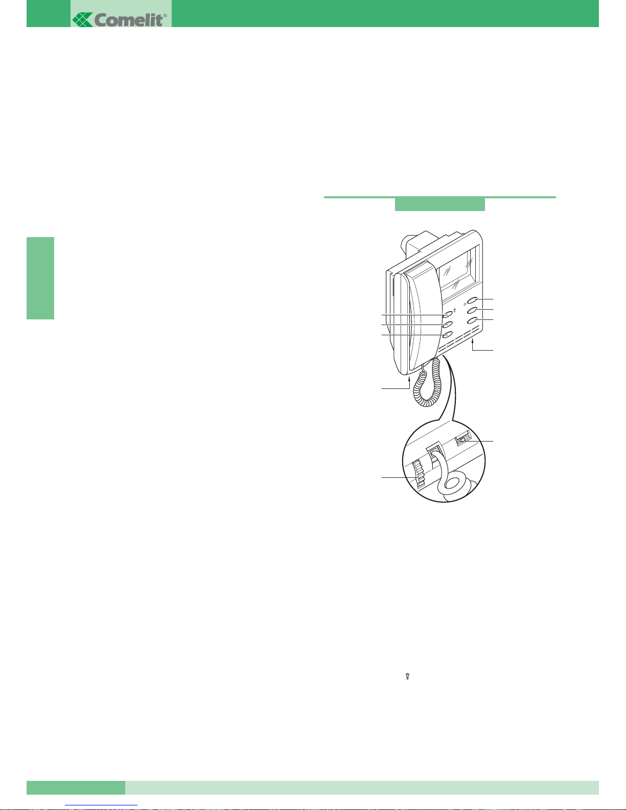
GROUP S.P.A.
MT SB2 01
46
FRANÇAIS
GENERALITES
Le système “Simplebus2” se caractérise par la simplicité de son
câblage qui présente seulement 2 fils non polarisés dans chaque
tronçon de l’installation. De ce fait, aucune alimentation locale ou
centralisée au moyen de conducteurs additionnels n’est alors
plus nécessaire.
La technologie entièrement à 2 fils offre donc l’avantage de ne plus
devoir se préoccuper du nombre de conducteurs à dériver du
montant principal, ni du type de plaque de rue à installer.
Le remplacement d’un poste intérieur parlophonique par un poste
intérieur visiophonique est immédiat.
Associé à la plaque de rue “Powercom” - caractérisée par sa
grande facilité d’installation grâce à sa modularité - le système
“Simplebus2” est extrêmement simple à câbler en éliminant toute
possibilité d’erreur, tout en réduisant drastiquement les temps
d’installation.
En outre, une vaste gamme d’accessoires permet de résoudre
facilement n’importe quelle exigence d’installation.
Ce système est en mesure de gérer jusqu’à 240 usagers en
connectant au maximum 3 dérivés avec le même code usager.
De série, il monte les fonctions d’ouvre-porte, d’appel au HP-micro
auxiliaire et de Autoallumage. De plus, des cartes en option sont
disponibles pour toute exigence particulière (par ex. leds et
boutons additionnels).
Pour la description complète des articles concernant l’installation
Simplebus2, voir le catalogue 66.
AVERTISSEMENTS
Suivre scrupuleusement les instructions fournies par le constructeur.
Tous les appareils qui composent l’installation doivent impérativement
être destinés à l’usage pour lequel ils ont été conçus.
La société COMELIT GROUP S.p.A. décline toute responsabilité
quant à tout préjudice matériel ou corporel qui se vérifierait à la
suite d’une utilisation impropre des appareils, de modifications
effectuées par d’autres à quelque titre et pour quelque objectif que
ce soit et de l’emploi d’accessoires et de matériaux non d’origine.
Effectuer les installations conformément aux normes en vigueur.
Tous les produits sont conformes aux prescriptions contenues
dans les directives CEE 73/23-89/336 et cela est attesté par la
présence du marquage CE.
Eviter de placer les fils du montant à proximité de câbles
d’alimentation (220/380V).
Avertissement pour l’usager
En cas de panne ou de dysfonctionnement d’une partie
quelconque de l’installation, veuillez vous adresser exclusivement
à l’installateur ou à des techniciens spécialisés.
POSTES INTERIEURS VIDEO
Instructions pour la sécurité
Pour limiter le risque de pannes et de décharges électriques:
•
ne pas retirer le couvercle ni effectuer personnellement les réparations.
Si besoin est, demander l’intervention de techniciens spécialisés.
• Ne jamais introduire des objets ni verser des liquides à l’intérieur
du dispositif.
• Ne jamais entraver la circulation de l’air en bouchant les fentes
prévues à cet effet.
Moniteur semi-encastrable série Videocom (tube court)
Caractéristiques techniques:
Moniteur de la série Videocom, dimensions: 193x223x65 mm,
semi-encastrable (49 mm de profondeur murale), couleur blanc
RAL9010, avec écran en N/B de 4,5”, vision directe. Il peut s’installer
sur le boîtier Art. 4514, mais aussi sur des boîtiers à encastrer pour
séries civiles de 3 modules DIN (Art. 4517), voir page 49.
A compléter avec la bride Art. 4714W/2.
Le moniteur est muni de:
1. Crochets de fixation à la bride.
2. Réglage de la luminosité (tourner pour varier l’intensité).
3. Réglage du volume d’appel (déplacer vers la gauche pour
augmenter le volume).
4. Bouton ouvre-porte
().
5. Bouton d’appel au standard / libre (1).
6. Bouton de Autoallumage / demande vidéo (2).
7. Bouton d’actionnement * (3).
8. Bouton Privacy * (4).
9. LED * (0).
* disponibles seulement avec la carte en option Art. 4703W.
Art. 4700W
1
2
4
3
4
5
6
9
1
3
2
1
8
7
Page 48
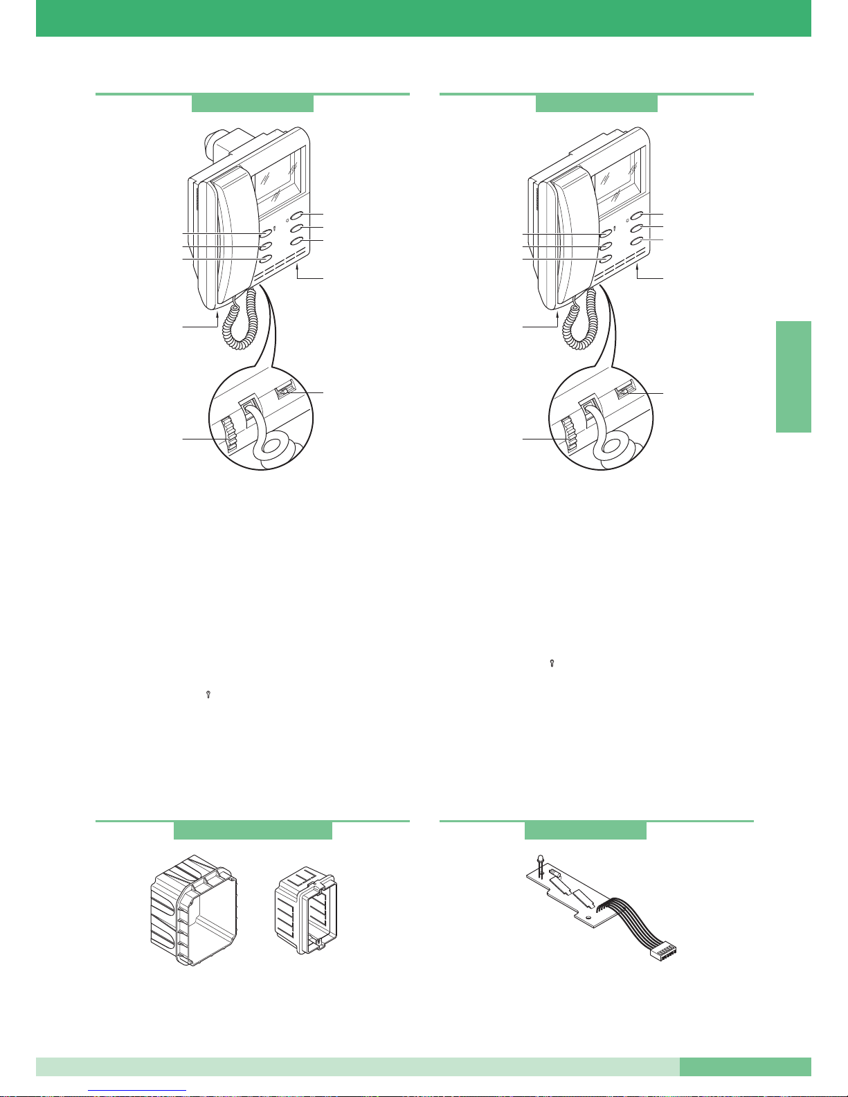
MT SB2 01
47
MT SB2 01
FRANÇAIS
Moniteur semi-encastrable série Videocom (tube long)
Caractéristiques techniques:
Moniteur de la série Videocom, dimensions: 193x223x65 mm,
à encastrer (68 mm de profondeur murale), couleur blanc
RAL9010, avec écran en N/B de 4,5”, vision directe. A installer
uniquement sur le boîtier à encastrer Art. 4514, voir page 49.
A compléter avec la bride Art. 4714W/2.
Le moniteur est muni de:
1. Crochets de fixation à la bride.
2. Réglage de la luminosité (tourner pour varier l’intensité).
3. Réglage du volume d’appel (déplacer vers la gauche pour
augmenter le volume).
4. Bouton ouvre-porte
().
5. Bouton d’appel au standard / libre (1).
6. Bouton Autoallumage / demande vidéo (2).
7. Bouton d’actionnement * (3).
8. Bouton Privacy * (4).
9. LED * (0).
* disponibles seulement avec la carte en option Art. 4703W.
Art. 4514 boîtier à encastrer moniteur Art. 4700W et Art. 4700W/I.
Art. 4517 boîtier série civile 3 modules DIN utilisable pour
encastrer le moniteur Art. 4700W.
Moniteur mural série Videocom
Caractéristiques techniques:
Moniteur de la série Videocom, dimensions: 193x223x65 mm,
mural, couleur blanc RAL9010, avec écran en N/B de 4,5”,
vision directe. A compléter avec la bride Art. 4714W/2.
Le moniteur est muni de:
1. Crochets de fixation à la bride.
2. Réglage de la luminosité (tourner pour varier l’intensité).
3. Réglage du volume d’appel (déplacer vers la gauche pour
augmenter le volume).
4. Bouton ouvre-porte
().
5. Bouton d’appel au standard / libre (1).
6. Bouton de Autoallumage / demande vidéo (2).
7. Bouton actionneur * (3).
8. Bouton Privacy * (4).
9. LED * (0).
* disponibles seulement avec la carte en option Art. 4703W.
L’utilisation du moniteur Videocom, ancienne série 4701W risque
de provoquer des problèmes de fonctionnement.
Art. 4700W/I
1
2
4
3
4
5
6
9
1
3
2
1
8
7
Art. 4701W/A
1
2
4
3
4
5
6
1
3
2
1
9
8
7
Art. 4514W et Art. 4517
Cartes boutons additionnels et LED
Carte en option avec 2 boutons additionnels et LED de signalisation.
A introduire dans tous les moniteurs de la série Videocom.
Art. 4703
Page 49
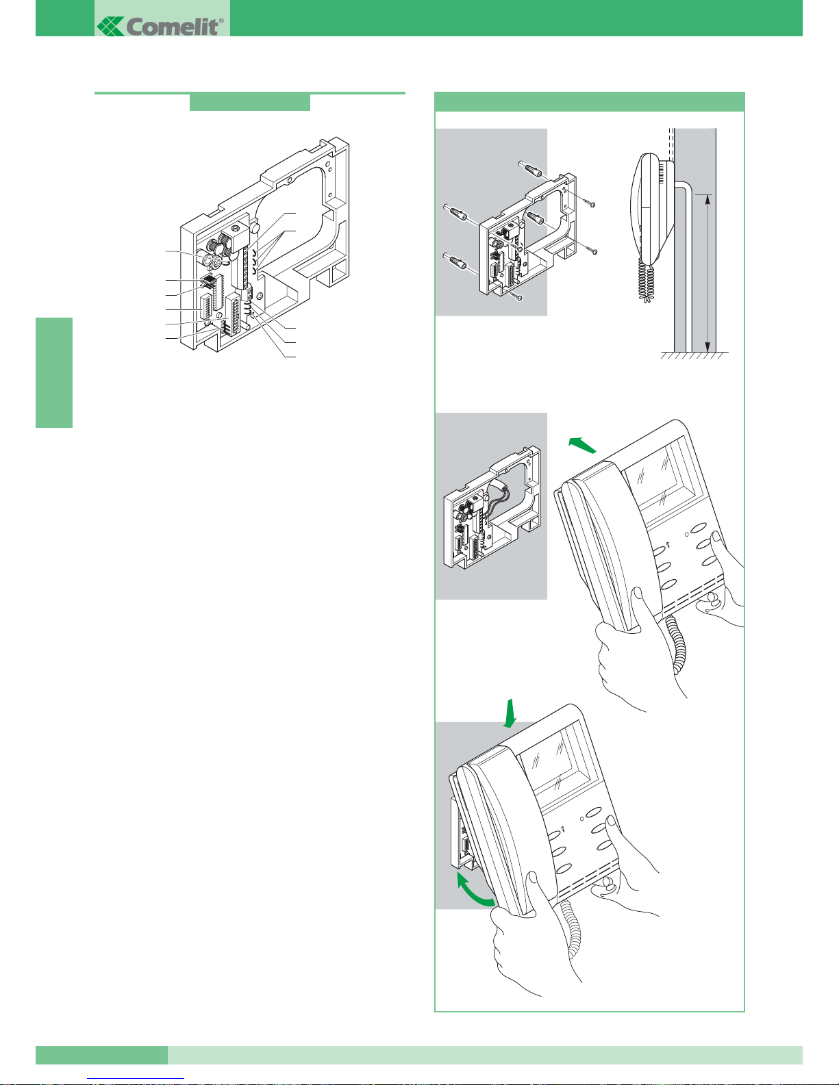
Bride Simplebus2
Bride de fixation du moniteur consentant l’installation murale du
moniteur ou au moyen de la base de table Art. 4712W (voir
page 49) et permettant la connexion des câbles de l’installation.
Munie de bornes pour la connexion de l’appel du palier (voir
variante G, page 111) pour la connexion d’un dispositif de répétition
de l’appel (voir SB2/D page 105) et pour l’utilisation du bouton 1 du
moniteur pour usages différents (voir variante E page 110).
Possibilité d’insérer jusqu’à 3 brides ayant le même code usager
dans la même installation (voir page 98).
Compatible avec les installations Simplebus1.
Caractéristiques techniques
Dimensions: 158x121x24.
1. connecteur bride moniteur.
2. bornes de connexion de l’installation:
0 +20V bornes de connexion Art 1212/B.
L L connexion ligne bus.
CFP CFP entrée appel du palier.
P1 C1 bouton pour usages divers. Pour avoir un contact
libre NO, couper les cavaliers CV3 et CV4.
S+ S- bornes pour le dispositif de répétition de l’appel.
3. CV5 Cavalier de débranchement vidéo.
4. JP1 jumper de validation de la demande vidéo
(voir variante F, page 110).
5. CN2 connecteur pour la programmation.
6. Dip switches pour la programmation du code usager.
7. CV1, CV2, CV7 cavaliers d’alimentation du moniteur additionnel
au moyen de l’Art. 1212/B (voir variante SB2/A3 page 101).
8. CV3, CV4 cavalier pour dégager le bouton 1.
9. CV6 cavalier de sélection du type de fonctionnement
(Simplebus2 ou Simplebus1).
10. JP2 jumper de sélection du type de fonctionnement
(Simplebus2 ou Simplebus1).
Art. 4714W/2
7
1
6
4
5
2
8
9
8
3
10
147
cm
1
2
3
4
1
2
1
2
3
4
Installation moniteur mural Art. 4701W/A
GROUP S.P.A.
MT SB2 01
48
FRANÇAIS
Page 50
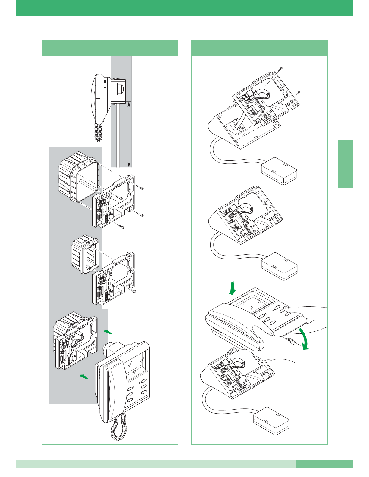
145
cm
1
2
4
3
Art. 4514
Art. 4517
solo per monitor
Art. 4700W
Art.
4700W
4700W/I
Per monitor
Installation moniteur mural Art. 4700W
et Art. 4700W/I
2
1
4
3
1
2
Installation base de table Art. 4712W
pour moniteur Art. 4701W/A et Art. 4700W
Pour
moniteurs
Art. 4700W
4700W/I
seulement pour
moniteurs
Art. 4700W
MT SB2 01
49
MT SB2 01
FRANÇAIS
Page 51
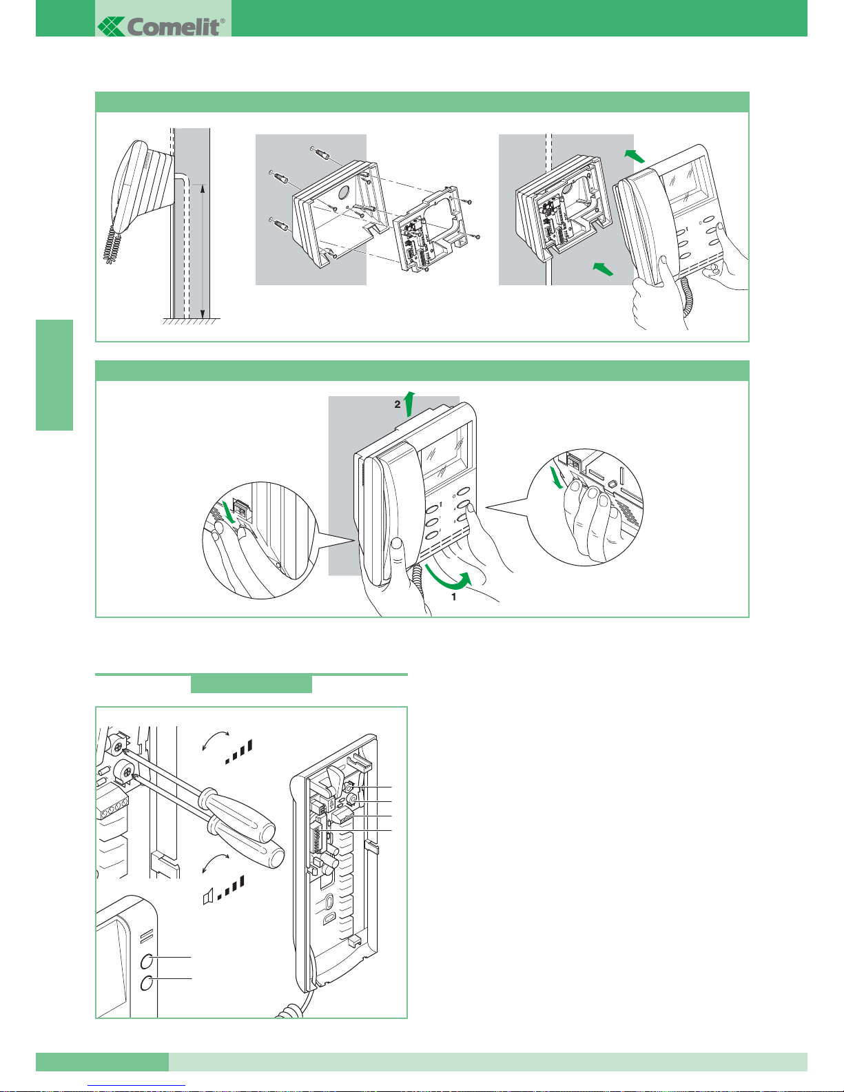
GROUP S.P.A.
MT SB2 01
50
FRANÇAIS
POSTES INTERIEURS AUDIO
Combiné parlophonique
Combiné parlophonique de la série Okay, dimensions 85x223x65
mm. Muni d’un bouton ouvre-porte et d’un bouton d’appel du
standard, utilisable comme bouton pour usages différents dans
les installations non équipées d’un HP-micro (voir variante A
page 108). Equipé d’une série de fonctions d’appel du palier
(voir variante B page 108). Possibilité de monter jusqu’à 3 combinés
parlophoniques ayant le même code usager dans la même
installation. Pour programmer le code usager voir : “Programmation
des combiné parlophonique Art. 2408W/A, 2428W et bride Art.
4714W/2” à la page 62.
A utiliser uniquement pour des installations audio.
Caractéristiques techniques:
1. Bouton ouvre-porte.
2. Bouton d’appel du standard / bouton pour usages divers présent
dans la boîte à bornes (AB).
3. Bornes de connexion à l’installation:
L L connexion à la ligne bus.
CFP CFP entrée appel du palier.
AB bouton normalement destiné à des services divers.
Pour avoir un contact libre NO couper les cavaliers CV1 et CV2.
4. Dip switches de programmation du code usager (voir page 63).
5. Trimmer de réglage du volume du micro.
6. Trimmer de réglage du volume de la sonnerie.
147 cm
Art. 4704
1
2
4
3
Art. 4700W
1
2
+
-
+
-
MIC
5
6
3
4
Installation moniteur semi-encastrable Art. 4700W avec adaptateur mural Art. 4704
Comment déposer le moniteur
Art. 2408W/A
Page 52
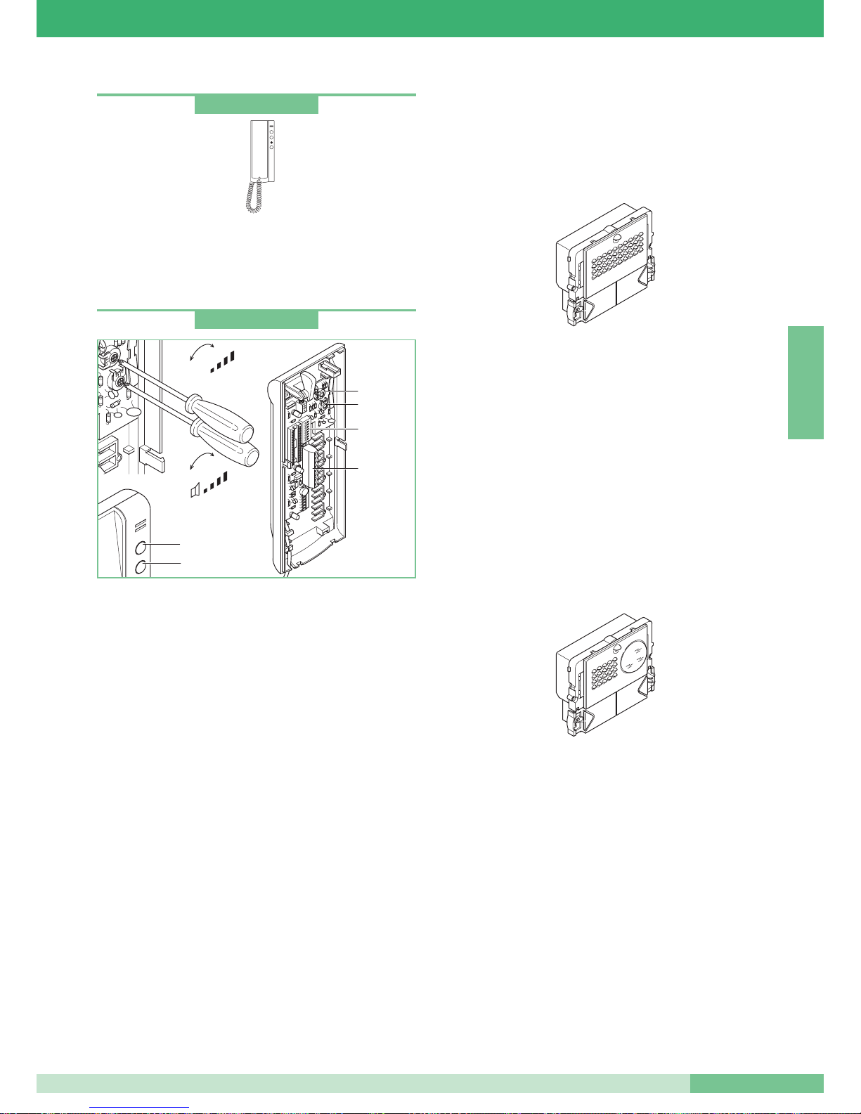
MT SB2 01
51
MT SB2 01
FRANÇAIS
Combiné parlophonique
Combiné parlophonique comme l’Art. 2408W/A avec adjonction d’un
interrupteur et d’une led additionnelle pour le service Privacy ou Docteur
(ouverture automatique de la gâche électrique à la suite d’un appel).
Pour la connexion à l’installation, voir la fiche technique dans
l’emballage de l’article.
Combiné parlophonique
Combiné parlophonique de la série Okay, dimensions 85x223x65 mm.
Muni d’un bouton ouvre-porte et d’un bouton d’appel du standard,
utilisable pour des usages différents dans les installations non équipées
d’un standard (voir variante C page 109). Equipé d’une série de
fonctions d’appel du palier (voir variante D page 109) et de répétition de
l’appel (voir SB2/D page 105). Combiné parlophonique à monter dans
les installations mixtes audio-vidéo en amont de l’Art. 4896 ou dans des
installations audio en cas de nécessité d’une fonction de répétition de
l’appel. Possibilité de monter jusqu’à 3 combinés parlophoniques ayant
le même code usager dans la même installation. Pour la modalité
d’insertion de combinés parlophoniques additionnels ayant le même
code usager, voir les variantes SB2/A4 et SB2/A5 page 102. Pour la
programmation du code usager, voir "Programmation des combiné
parlophonique Art. 2408W/A, 2428W et la bride Art. 4714W/2" page 62.
Caractéristiques techniques:
1. Bouton ouvre-porte.
2. Bouton d’appel du standard / bouton pour usages divers présent
dans la boîte à bornes (P1 C1).
3. Bornes de connexion à l’installation:
L L connexion à la ligne bus.
CFP CFP entrée appel du palier.
P1 C1 bouton normalement destiné à des services divers.
Pour avoir un contact libre NO couper les cavaliers CV2 et CV3.
S+ S-
bornes de connexion d’un dispositif de répétition de la sonnerie.
4. Dip switches de programmation du code usager (voir page 63).
5. Trimmer de réglage du volume du micro.
6. Trimmer de réglage du volume de la sonnerie.
5
6
1
2
4
3
+
-
+
-
MIC
Art. 2410W
Art. 2428W
PLAQUES DE RUE
Les installations Simplebus2 peuvent monter des plaques de rue Série
Powercom, Vandalcom et Logicom. Pour les séries Vandalcom et
Logicom, se référer à la fiche technique FT/SB/01 et au Catalogue 50.
HP-micro Série Powercom
Composé des Art. 3320 + Art. 1602.
HP-micro avec boîte à bornes et double amplificateur, haut-parleur
étanche et micro à électret.
Volume du micro et du haut-parleur réglable frontalement sur
l’Art.1602 (voir page 54); possibilité de réglage par le dos en cas
de montage sur l’Art. 3320.
Le micro est amovible pour améliorer le rendement sonore (voir
page 54). Bouton d’appel en alliage d’aluminium avec étiquette
porte-nom enlevable frontalement.
Equipé d’un microprocesseur et de dip switches à 8 positions pour
la programmation des appels aux usagers. Pour la programmation
des boutons voir page 64. Alimentation 12V CA (utiliser l’Art. 1195).
Fonction ouvre-porte par switch électronique embarqué (3A
seulement courant alternatif). Dimensions 112x89,5x40 mm.
HP-micros vidéo série Powercom
Se compose des Art. 3321 + Art. 4660.
Caméra orientable à haute sensibilité pinhole CCD 1/4” N/B.
Eclairage à l’infrarouge (6 LEDS).
Equipé d’une boîte à bornes et d’un HP micro avec double
amplificateur, haut-parleur étanche et micro à électret.
Volume du micro et du haut-parleur réglable frontalement sur
l’Art. 4660 (voir page 54); possibilité de réglage par le dos
en cas de montage sur l’Art. 3321.
Le micro est amovible pour améliorer le rendement sonore (voir
page 54). Bouton d’appel en alliage d’aluminium avec étiquette
porte-nom enlevable frontalement.
Equipé d’un microprocesseur et de dip switches à 8 positions
pour la programmation des appels aux usagers.
Pour la programmation des boutons voir page 64. Alimentation
12V CA (utiliser l’Art. 1195).
Fonction ouvre-porte par switch électronique embarqué
(3A seulement courant alternatif). Dimensions 112x89,5x40 mm.
Page 53
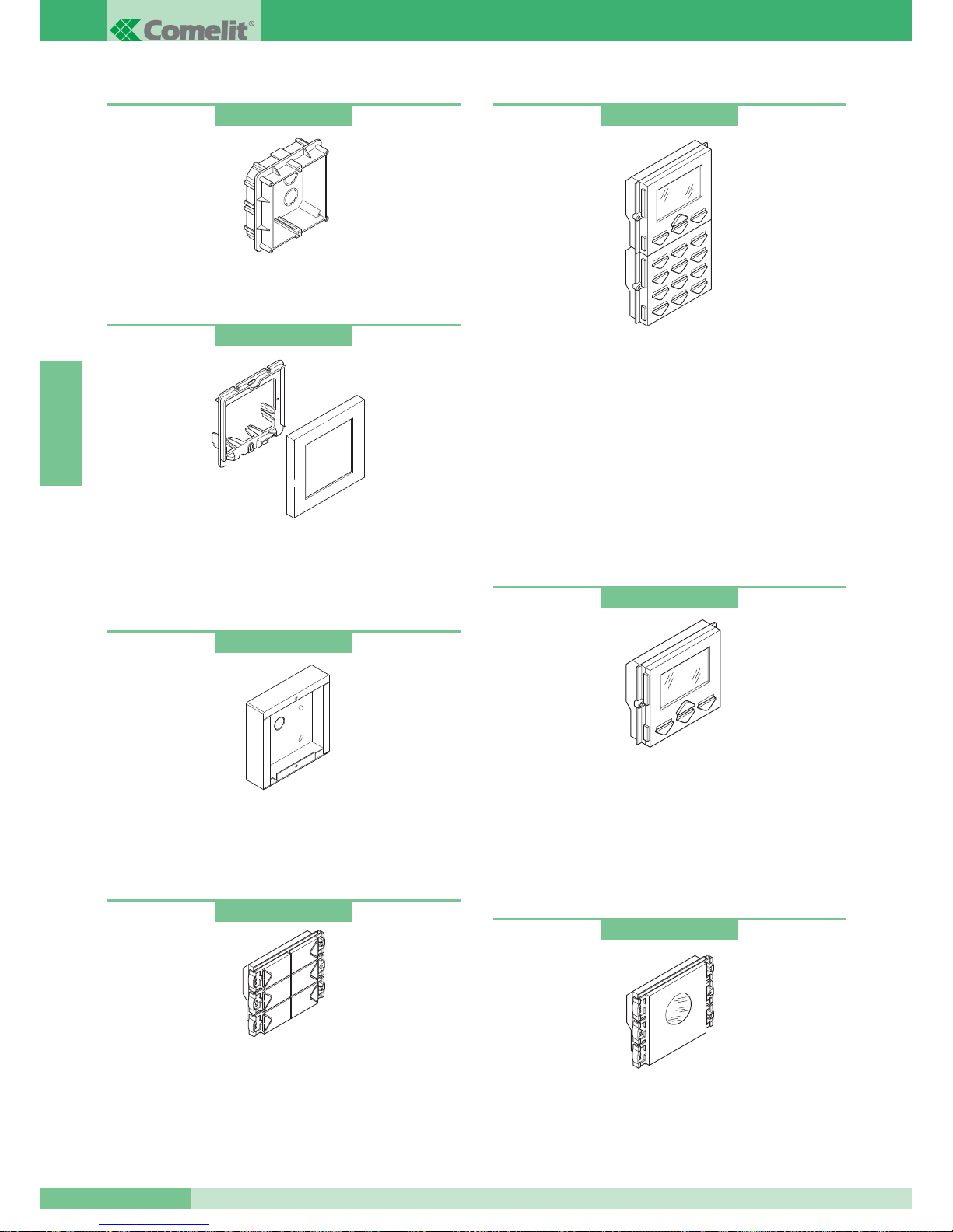
Module de signalisation de ligne occupée
Avec led bleue clignotante pour l’indication visuelle de l’état d’occupé.
L’étiquette transparente en carton est fournie neutre pour pouvoir
y écrire dans toutes les langues. Dimensions: 112x89,5x38 mm.
Module d’appel numérique avec répertoire électronique
Avec afficheur LCD graphique 128x64 dots, plaque de rue à 16
boutons rétroéclairés avec led bleue. Il fait aussi fonction de
digicode avec la possibilité d’entrer jusqu’à 250 mots de passe.
Il est équipé d’un module répertoire porte-noms électronique
mémorisant 400 noms d’usagers. Le défilement des noms
s’effectue en appuyant sur deux boutons de recherche ou en
numérisant directement l’initiale du nom ou le code usager. A
l’affichage du nom de l’usager désiré, il suffit d’appuyer sur le
bouton d’appel. L’entrée des noms des usagers s’effectue d’une
manière simple au moyen du programmateur art. 1230 ou du
logiciel pour micro-ordinateur PC art. 1249 ou du clavier codé.
Dimensions 112x180x40 mm.
Module répertoire électronique
Module répertoire porte-noms électronique, avec afficheur graphique
128x64 dots. Mémorise 400 noms d’usagers. Le défilement des
noms s’effectue en appuyant sur deux boutons de recherche. Après
affichage du nom de l’usager désiré il suffira d’appuyer sur le bouton
d’appel. La programmation des noms des usagers s’effectue
aisément au moyen du programmateur art. 1230 ou du logiciel pour
micro-ordinateur P.C. Art. 1249. Dimensions: 112x89,5x40 mm.
Art. 3342
Art. 3346
Art. 3340
Boîtiers à encastrer
Disponibles pour 1, 2 et 3 modules.
Dimensions un module 127x127x45 mm.
Modules boutons d’appel
Module avec boutons d’appel dotés de micro-switches et réalisés
en alliage d’aluminium moulé sous pression et chromé.
La led bleue d’éclairage des étiquettes porte-noms est enlevable
frontalement. Disponibles à 4 et 6 boutons. Dimensions
112x89,5x40 mm. Pour la programmation des boutons voir page 64.
Art. 3110
Art. 3323
Art. 3311
Art. 3316
Cadres porte-modules avec encadrement
Réalisés en aluminium moulé sous pression et revêtus de
peintures particulières résistant à l’environnement extérieur.
Disponibles pour 1, 2 et 3 modules dans les couleurs Gris, Blanc,
Bleu et Orange. Dimensions un module 125x125x15,5 mm.
Boîtiers saillie
Boîtier en acier inox. Disponible pour 1, 2, 3, 4, 6 et 9 modules.
Mural également pour environnement extérieur. Utile en cas
d’impossibilité d’encaisser le boîtier. Dimensions un module
123x123x32,5 mm.
GROUP S.P.A.
MT SB2 01
52
FRANÇAIS
Page 54
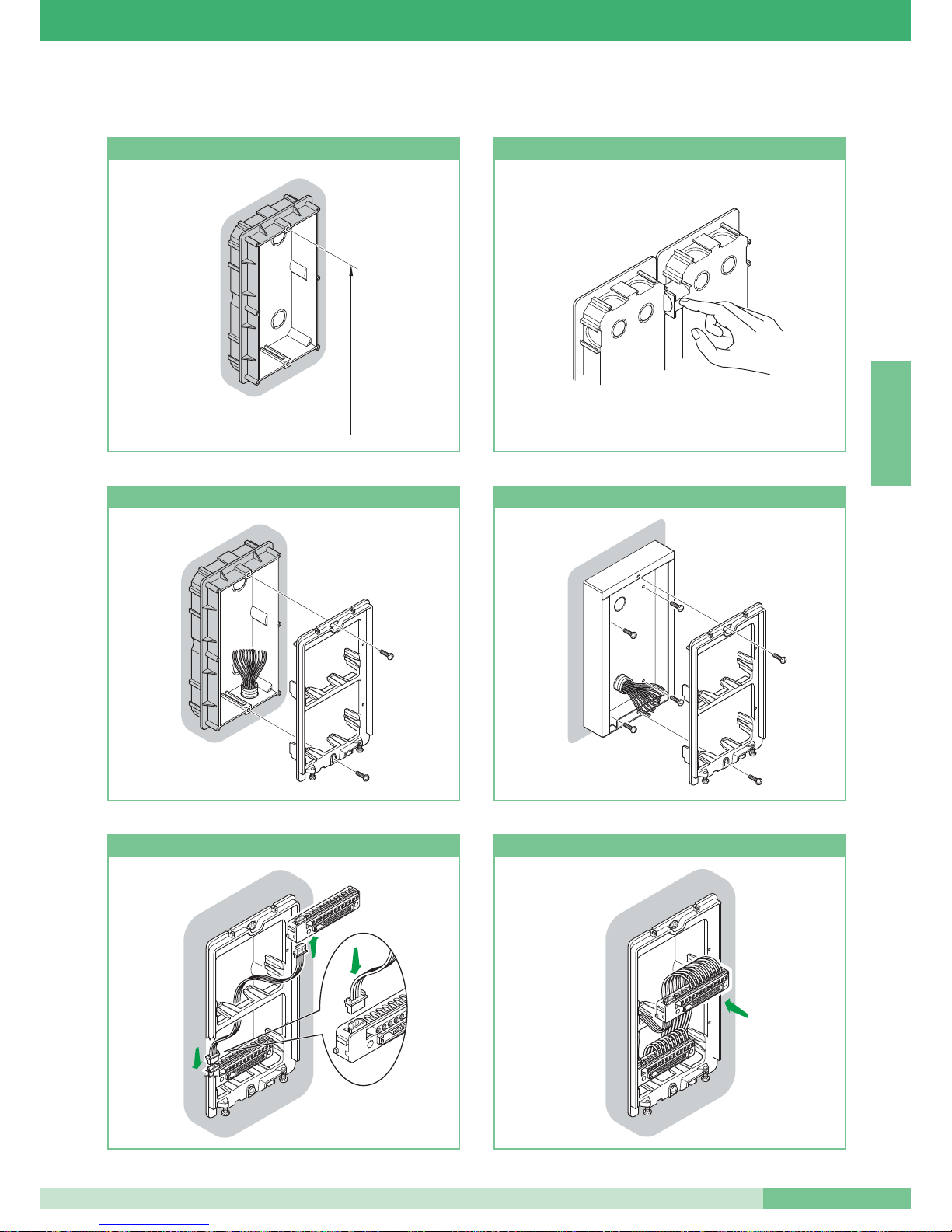
Instructions pour l’installation de la plaque de rue audio et vidéo
160 - 165 cm
Hauteur boîtier à encastrer Comment associer plusieurs boîtiers
Fixation du petit câble sur le boîtier à encastrer
Fixation du cadre sur le boîtier mural
Connexion cadre à 4 pôles Câblage boîte à bornes insérée ou retirée
MT SB2 01
53
MT SB2 01
FRANÇAIS
Page 55
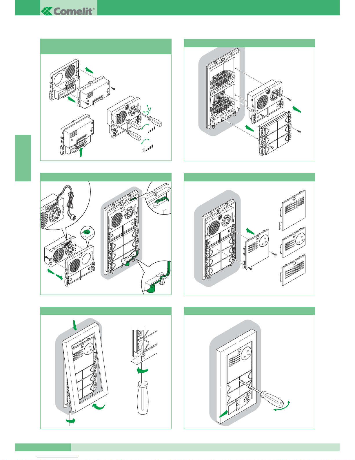
1
2
3
360˚
+
-
+
-
MIC
Montage connexions et réglages groupe
audio-vidéo
Introduction modules
2
3
5
1
4
Position alternative du micro
Pose/dépose éléments frontaux
Fixation cadre
C
arla
R
ossi
Pose/dépose étiquettes
open
close
GROUP S.P.A.
MT SB2 01
54
FRANÇAIS
Page 56
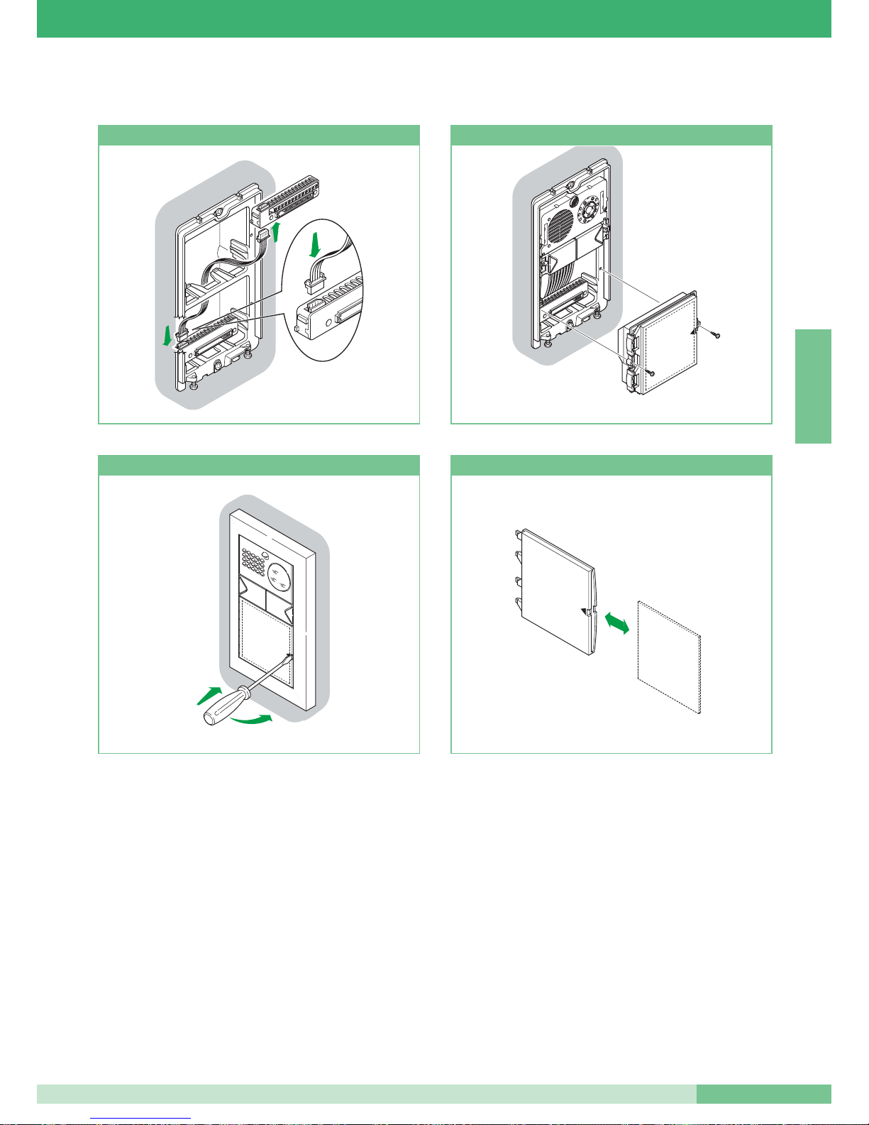
Connexion câble à 4 pôles
10
Introduction module
2
1
10
Retrait porte-étiquette
15
Introduction/retrait étiquette
Instructions pour le montage des modules d’information Art. 3326, Art. 3344 et Art. 3346
MT SB2 01
55
MT SB2 01
FRANÇAIS
Page 57
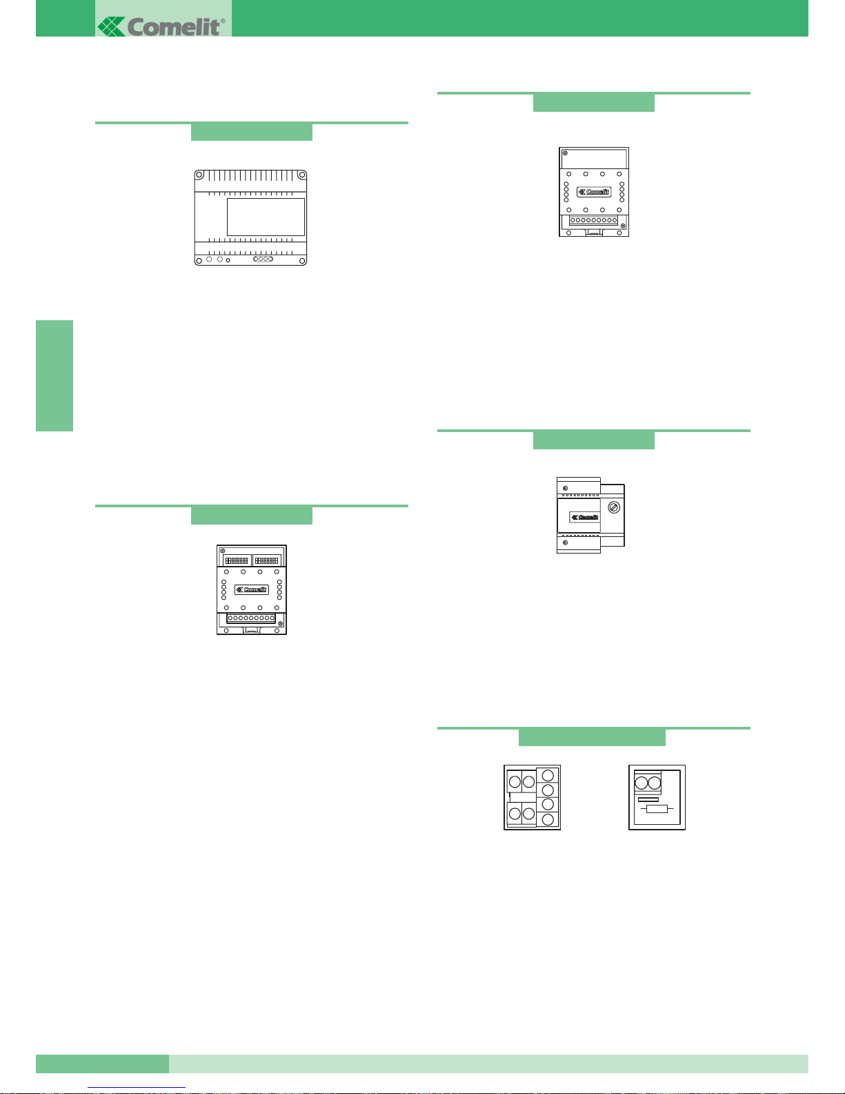
ALIMENTATIONS ET ACCESSOIRES
Transformateur pour mélangeur-alimentation
Transformateur 65VA. (T 1’on / 5’off).
Primaire 230VCA
Secondaire: OUT1: 36VAC 1,5A
OUT2: 14VAC 1A
Le transformateur est équipé d’un PTC intérieur de protection.
Dimensions: 107x90x60 (8 modules DIN).
Commutateur
Alimentation 12 VCA – 20 VCC.
Dimensions: 66x85x35 mm (4 modules DIN).
Bornes de connexion à l’installation:
~ ~ * alimentation 12VCA-20VCC.
LS LS entrée ligne bus plaque de rue secondaire.
LP LP entrée ligne bus plaque de rue principale.
LM LM sortie ligne bus du montant.
Pour la programmation du commutateur voir page 62.
Alimentation pour moniteur additionnel
Alimentation 15VA (interm.).
Entrée: 230VCA
Sortie: 0- 20VDC 700mA
Le transformateur est équipé d’un PTC intérieur de protection.
Dimensions: 87x105x65 (5 modules DIN).
Art. 1246
Borne de dérivation et borne de terminaison de ligne
Voir page 64 pour la configuration de l’Art. 1216 selon le câble
utilisé. Bornes de connexion à l’installation:
Lin Lin: entrée ligne montant.
Lout Lout: sortie ligne montant.
LM LM: ligne montant dérivée vers le moniteur/combiné
parlophonique.
+ +: bornes connexion alimentation pour compatibilité
avec les installations Simplebus1.
Art. 1212/B
Relais
Relais 12-24V CC-CA 5A pour usages généraux. Peut être
commandé directement par la sortie de répartition de l’appel
de la bride Art. 4714W/2 ou par les combinés parlophoniques
Art. 2428W. Dimensions: 66x85x35 mm (4 modules DIN).
Bornes connexion installation:
+ - alimentation relais.
C-NO-NC contacts relais.
Art. 1122/A
Art. 1214/2 et Art. 1216
Art. 1214/2
Art. 1216
Art. 1224
GROUP S.P.A.
MT SB2 01
56
FRANÇAIS
Page 58
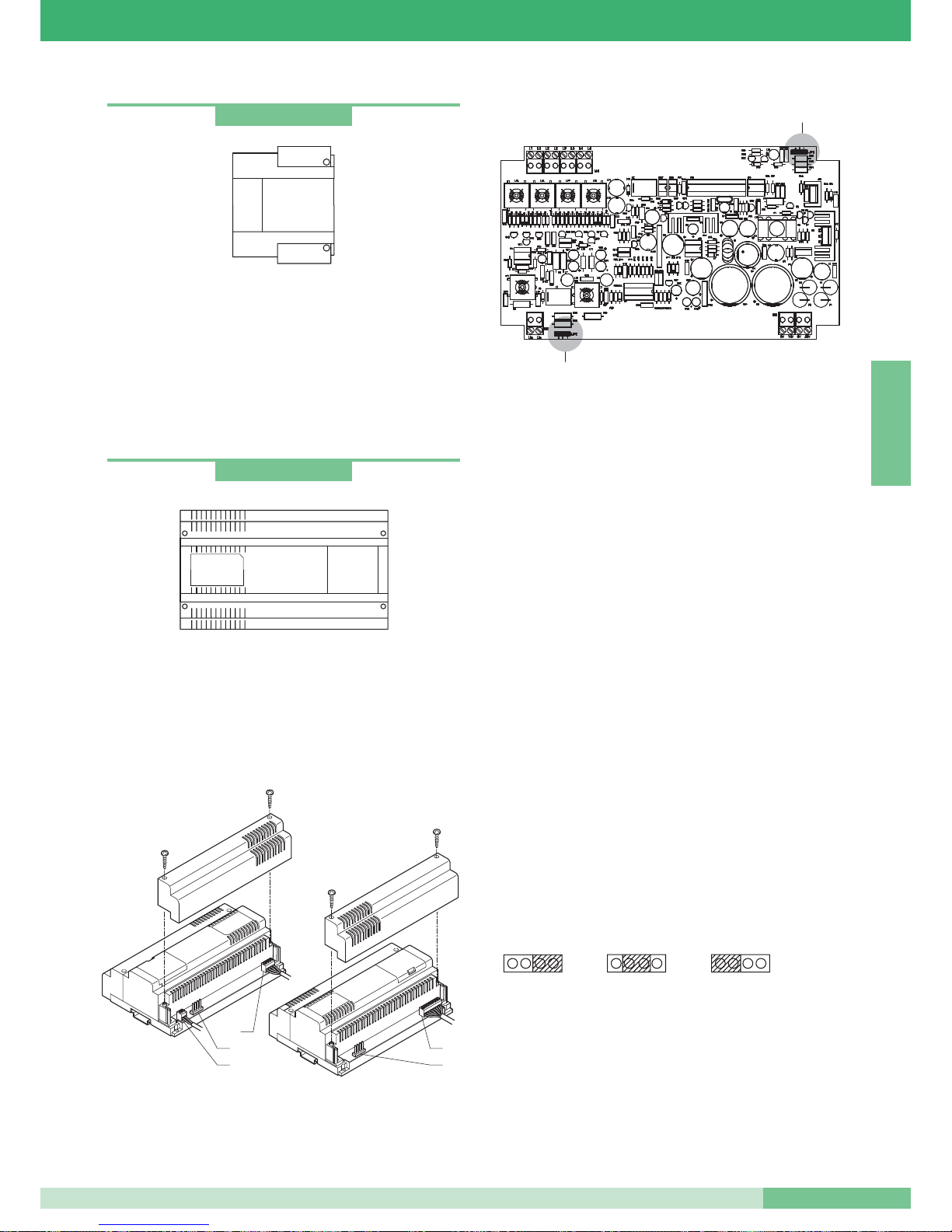
Transformateur
Transformateur 60VA (interm).
Primaire 230VAC
Secondaire: OUT1: 0-12V 1,5A
OUT2: 0-12V 1,5A
Le transformateur est équipé d’un fusible intérieur de protection.
Dimensions: 87x105x65 (5 modules DIN).
Mélangeur-alimentation
Le mélangeur-alimentation Art. 4896 est contenu dans un boîtier
à 12 modules DIN. Dimensions: 208x140x65 mm.
Pour pouvoir accéder aux bornes de connexion, retirer les
couvercles latéraux conformément aux indications illustrées
dans la figure.
Art. 4896
Art. 1195
4
1
3
4
2
JP1
JP2
L’Art. 4896 doit être alimenté par le transformateur Art.1246.
Exécuter les opérations de câblage et de connexion de l’installation
en débranchant l’alimentation de réseau.
Cet article est équipé d’un PTC de protection après un court-circuit,
pour le réactiver couper l’alimentation pendant environ une minute.
Brancher la ligne en entrée de la plaque de rue et alimenter ensuite
également le module mélangeur Art. 4896.
Le dispositif consent d’alimenter au maximum un moniteur et de
gérer au maximum
MAX 100 usagers.
Bornes de connexion de l’installation:
1. Lin Lin connexion à la ligne venant de la plaque de rue.
2.
0V 36V connexion aux bornes OUT1 du transformateur Art. 1246.
0V 14V connexion aux bornes OUT2 du transformateur Art. 1246.
3.
L1 L1 sortie dérivation 1 du montant.
L2 L2 sortie dérivation 2 du montant.
L3 L3 sortie dérivation 3 du montant.
L4 L4 sortie dérivation 4 du montant.
4. Jumpers à programmer selon le nombre total d’usagers
connectés au mélangeur –alimentation Art.4896.
JP1 et JP2 sur la
position 3 pour les installations ayant
de 0 à 15 usagers
JP1 et JP2 sur la position 2 pour les installations ayant
de 16 à 35 usagers
JP1 et JP2 sur la position 1 pour les installations ayant
de 36 à 100 usagers.
JP1 - JP2
2
3
1
MT SB2 01
57
MT SB2 01
FRANÇAIS
Page 59
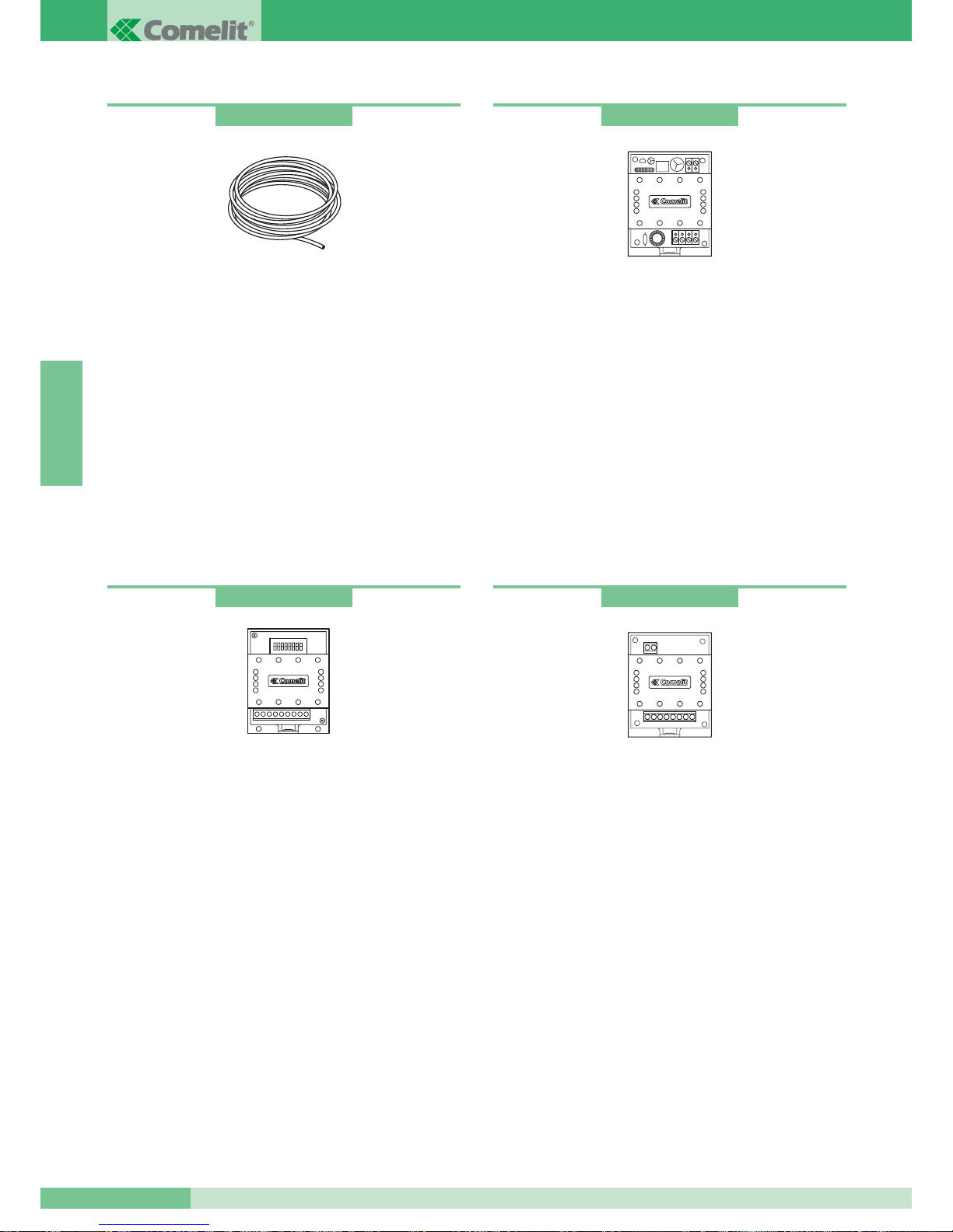
Amplificateur de ligne
Amplificateur pour installations vidéo Simplebus1.
Il régénère le signal du montant relativement au composant vidéo.
Alimentation: 12V CA ou 20V CC.
A monter exclusivement sur le tronçon en entrée aux
mélangeurs-alimentations Art. 4896.
Dimensions: 66x85x35 mm (4 modules DIN).
Bornes connexion installation:
Lin Lin: entrée ligne montant.
Lout Lout: sortie ligne montant.
~+ ~-: alimentation module.
Art. 4833/A
Concentrateur de ligne
Concentrateur de ligne pour installation Simplebus vidéo.
Il permet de distribuer le signal sur 4 montants.
A monter exclusivement sur le tronçon d’installation en entrée dans
les mélangeurs art. 4896.
Dimensions: 66x85x35 mm (4 modules DIN).
Bornes connexion installation:
Lin Lin: entrée ligne montant.
L1 L1: sortie dérivation 1 du montant.
L2 L2: sortie dérivation 2 du montant.
L3 L3: sortie dérivation 3 du montant
(couper la résistance avant d’introduire les câbles).
L4 L4: sortie dérivation 4 du montant
(couper la résistance avant d’introduire les câbles).
Art. 4834/2
Câble Comelit Simplebus2
Câble spécial pour les installations Simplebus2: il se compose de
deux conducteurs ayant une section de 1mm
2
tressés de couleur
rouge et noire. Disponibles en bobines de 100 et de 500 m.
Relais pour services divers
Alimentation 12VCA, 20VCC.
Portée relais: 10A.
Cet accessoire permet:
• service répétition sonnerie.
• service commande relais du poste intérieur dans des installations
sans standard.
• service éclairage escalier.
• service ouvre-porte secondaire.
Pour le câblage et l’explication des services voir la documentation
de l’Art. 1254.
Art. 4577
Art. 1254
GROUP S.P.A.
MT SB2 01
58
FRANÇAIS
Page 60
REGLES D’INSTALLATION
Règles d’installation pour installations visiophoniques
Eviter de placer les fils du montant à proximité de câbles
d’alimentation (220/380V).
Dans les dérivations vers chaque usager, introduire sur le montant
la borne Art. 1214/2 fournie avec la bride Art. 4714W/2 ou en vente
séparément pour les combinés parlophoniques Art. 2428W.
Terminer chaque montant ou chaque dérivation par l’Art. 1216
fourni avec le mélangeur-alimentation Art. 4896 et avec le module
vidéo Art. 4660. En fonction du câble utilisé pour le montant
programmer la fermeture sur l’Art. 1216 comme illustré dans le
tableau de la page 64.
En fonction du câble utilisé pour le montant, évaluer la distance
maximum pouvant être atteinte entre l’alimentation-mélangeur
Art.4896 et le moniteur le plus éloigné et entre la borne de
dérivation Art. 1214/2 et le moniteur le plus éloigné.
En fonction du câble utilisé pour la connexion évaluer la distance
maximum pouvant être atteinte entre la plaque de rue vidéo et le
mélangeur-alimentation Art. 4896.
Se référer aux tableaux de la page 60 pour évaluer les distances
en fonction des conducteurs.
Chaque Art.4896 peut gérer au
MAX 4 dérivations du montant
voir variante SB2/B page 103.
En cas d’installations munies de portes principales et secondaires
(voir schéma SB2V/EN/112 page 97) il faudra employer le
concentrateur de ligne Art. 4834/2 et le commutateur Art. 1224.
S'il y a une seule porte, on pourra brancher
jusqu’à 4 mélangeursalimentations Art. 4896 après l’Art. 4834/2 (voir le schéma
SB2V/012 page 94).
Chaque Art. 4834/2 permet au
MAX 4 dérivations: en cas de
nécessité de plusieurs dérivations (jusqu’à 16) il faudra mettre en
cascade deux Art. 4834/2. L’Art. 4834/2 additionnel doit être
précédé de son amplificateur de signal vidéo correspondant Art.
4833/A (voir variante SB2/C page 104). Possibilité d’insérer
jusqu’au
MAX 2 Art.4834/2 en cascade.
Le nombre MAX d’usagers pouvant être branché à un seul
mélangeur-alimentation Art. 4896 est de 100 usagers,
indépendamment qu’ils soient distribués sur un seul montant
ou sur plusieurs dérivations du montant (ex 100 usagers sur un
montant ou 25 usagers sur chacune des 4 dérivations du montant).
Possibilité de brancher
jusqu’à 25 moniteurs en cascade pour
chaque dérivation du montant (voir variante SB2/G page 106);
dans ce cas, pour déterminer la distance
MAX
entre la plaque de rue et le dernier moniteur de la cascade,
se référer au tableau page 60 colonne
A.
La connexion entre plusieurs moniteurs ayant le même
code usager (MAX 3) peut avoir lieu en cascade ou en dérivation
du montant en suivant les variantes SB2/A1-A2-A3-A4-A5
(pages 99-100-101-102).
Les combinés parlophoniques Art. 2428W ayant le même code
usager que le moniteur doivent être dérivés directement du
montant au moyen de l’Art. 1214/2.
L’Art. 4896 alimente
un seul moniteur pour chaque appel,
par conséquent, pour les installations avec plusieurs
moniteurs ayant le même code usager, il faudra programmer
les moniteurs additionnels comme
secondaires ou alimenter
séparément à travers l’Art.1212/B chaque moniteur additionnel
(voir pages 99-100-101).
Programmer les cavaliers et les jumpers sur la bride Art. 4714W/2
de la manière illustrée dans les variantes aux schémas de base
SB2/A1-A2-A3, selon la configuration que l’on désire obtenir.
Ne jamais orienter les caméras des plaques de rue vers des
sources de lumière directe (ex. lampes, lumière solaire, surfaces
réfléchissantes, etc….).
MT SB2 01
59
MT SB2 01
FRANÇAIS
Page 61
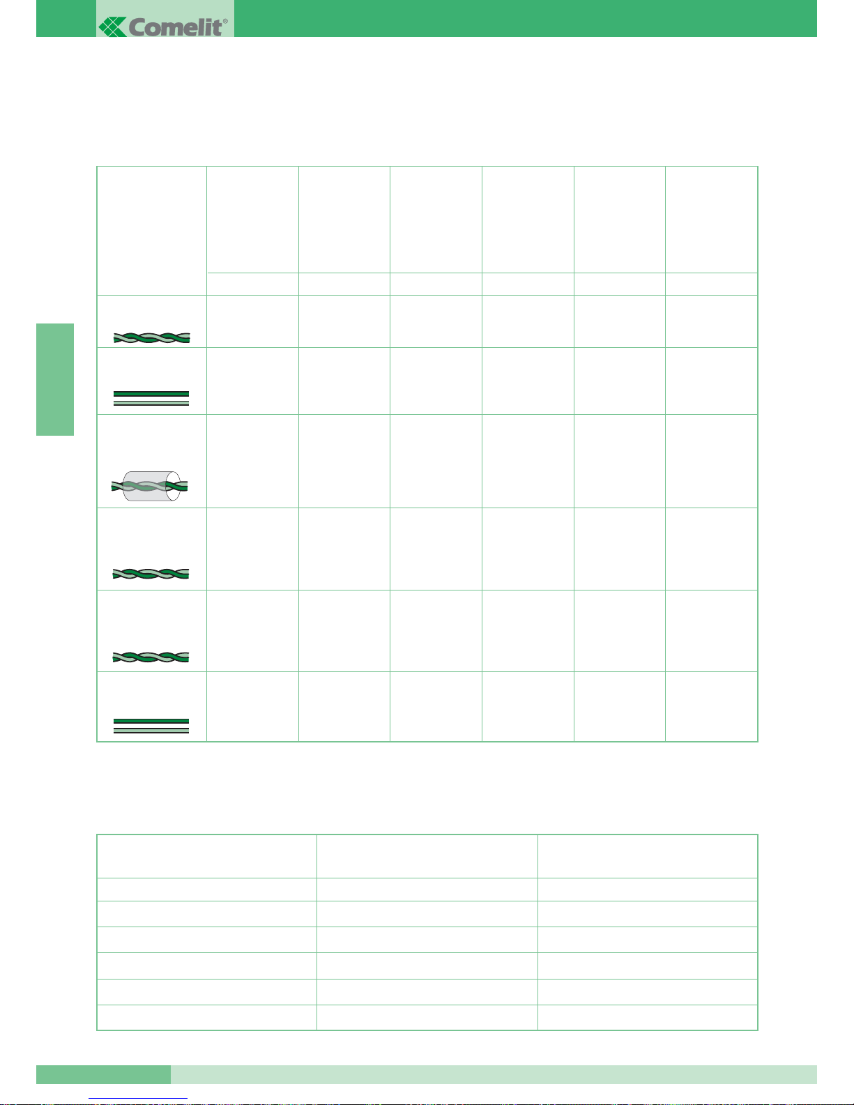
Distances maximums caractéristiques des conducteurs
La connexion des appareils est de type non polarisé.
L’emploi de conducteurs ayant des caractéristiques différentes de celles prescrites ne garantit pas l’obtention de distances d’intervention
déterminées, ni la bonne qualité du signal vidéo. Veuillez utiliser exclusivement les câbles décrits dans les tableaux suivants.
Distances maximums pouvant être atteintes pour les conducteurs d’alimentation du moniteur additionnel et de la plaque de rue
Type de câble
Boucle téléphonique
retorse (sect. 0,28 mm
2
(Ø 6/10)*
Câble UTP5 cat. 5
AWG 24 (sect.
0,2 mm
2
(Ø 5/10) *
200 m
150 m
120 m
100 m
200 m
100 m
80 m
150 m
200 m
100 m
80 m
150 m
200 m
100 m
80 m
150 m
150 m
80 m
50 m
100 m
ABCDE
Distance MAX
entre le mélangeur
Art. 4896 et le
poste intérieur.
Distance MAX
entre la plaque
de rue et le
mélangeur
Art. 4896.
Distance MAX
entre la plaque
de rue et
l’Art. 4833/A.
Distance MAX
entre l’Art. 4833/A
et le mélangeur
Art. 4896.
Distance MAX entre
la plaque de rue et
le mélangeur
ou l’amplificateur
Art. 4833/A avec un
Art. 4834/2 branché.
60 m
40 m
30 m
40 m
80 m 150 m 150 m 150 m 100 m 40 m
H
Distance MAX
entre la borne
de dérivation 1
Art. 1214/2 et le
poste intérieur.
Câble Comelit Art. 4577
sect. 1 mm
2
(Ø 12/10)
Câble bifilaire sect.
1,5 mm
2
(Ø 14/10)**
Câble tressé et blindé
sect. 1 mm
2
(Ø 12/10)*
Section du conducteur
4 m
10 m
20 m
30 m
40 m
10 m
25 m
50 m
100 m
150 m
FG
Distance MAX entre le transformateur
Art. 1195 et la plaque de rue.
Distance MAX entre l’alimentation
Art. 1212/B et le poste intérieur.
0,28 mm
2
(Ø6/10)
0,5 mm
2
(Ø8/10)
1 mm
2
(Ø12/10)
1,5 mm
2
(Ø14/10)
2 mm
2
(Ø16/10)
Câble bifilaire sect. 0,5
mm
2
(Ø 8/10) **
120 m 100 m 100 m 100 m 80 m 40 m
* Dans le cas où on utilise un câble multipaires torsadées, on doit utiliser uniquement une paire torsadée disponible. Dans le cas de grande
longueur afin de réduire la perte on utilise une paire comme un fil simple.
** Dans le cas d’un câble multifils, il faut utiliser seulement deux fils disponibles et ne pas mettre plusieurs fils en parallel.
GROUP S.P.A.
MT SB2 01
60
FRANÇAIS
Page 62
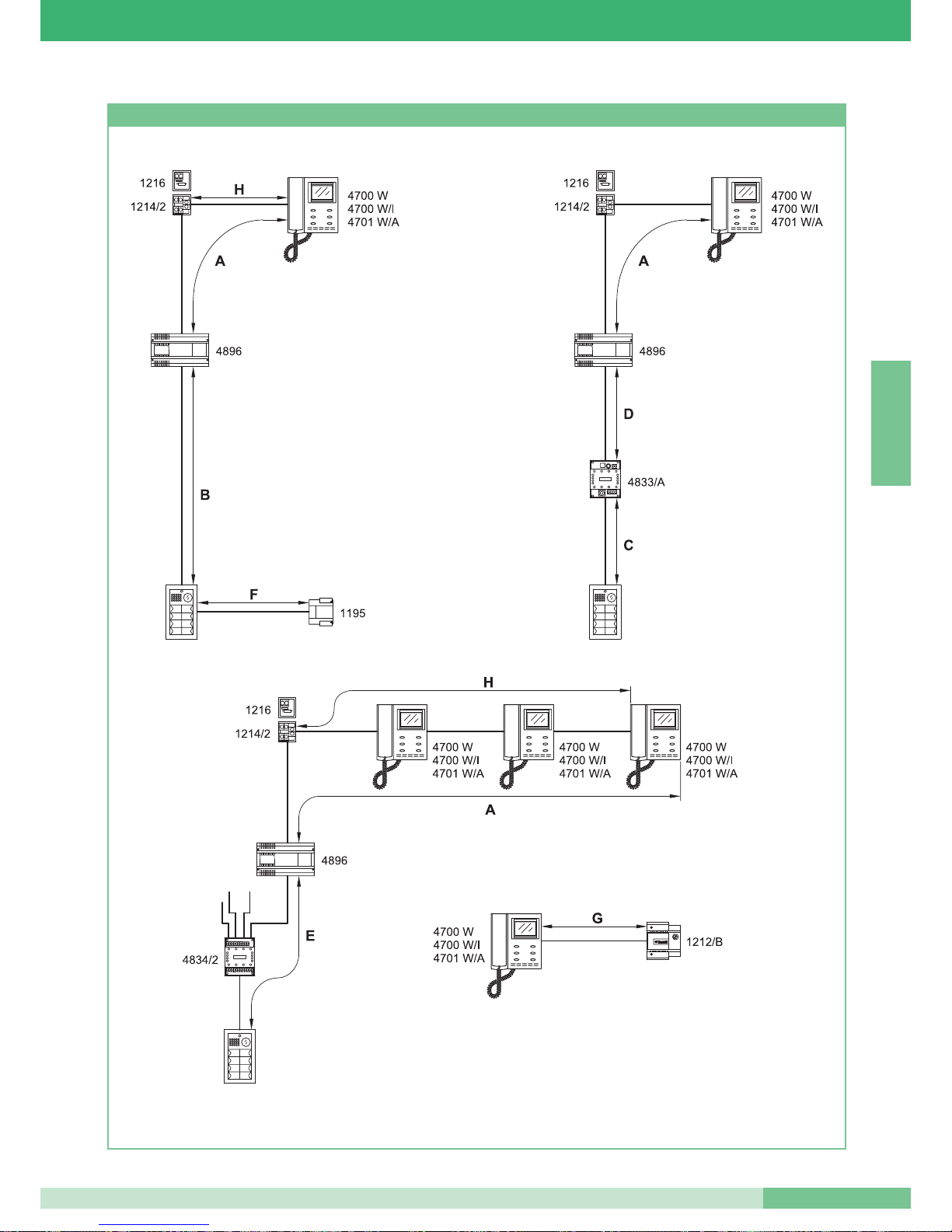
Figures pour les distances
MT SB2 01
61
MT SB2 01
FRANÇAIS
Page 63
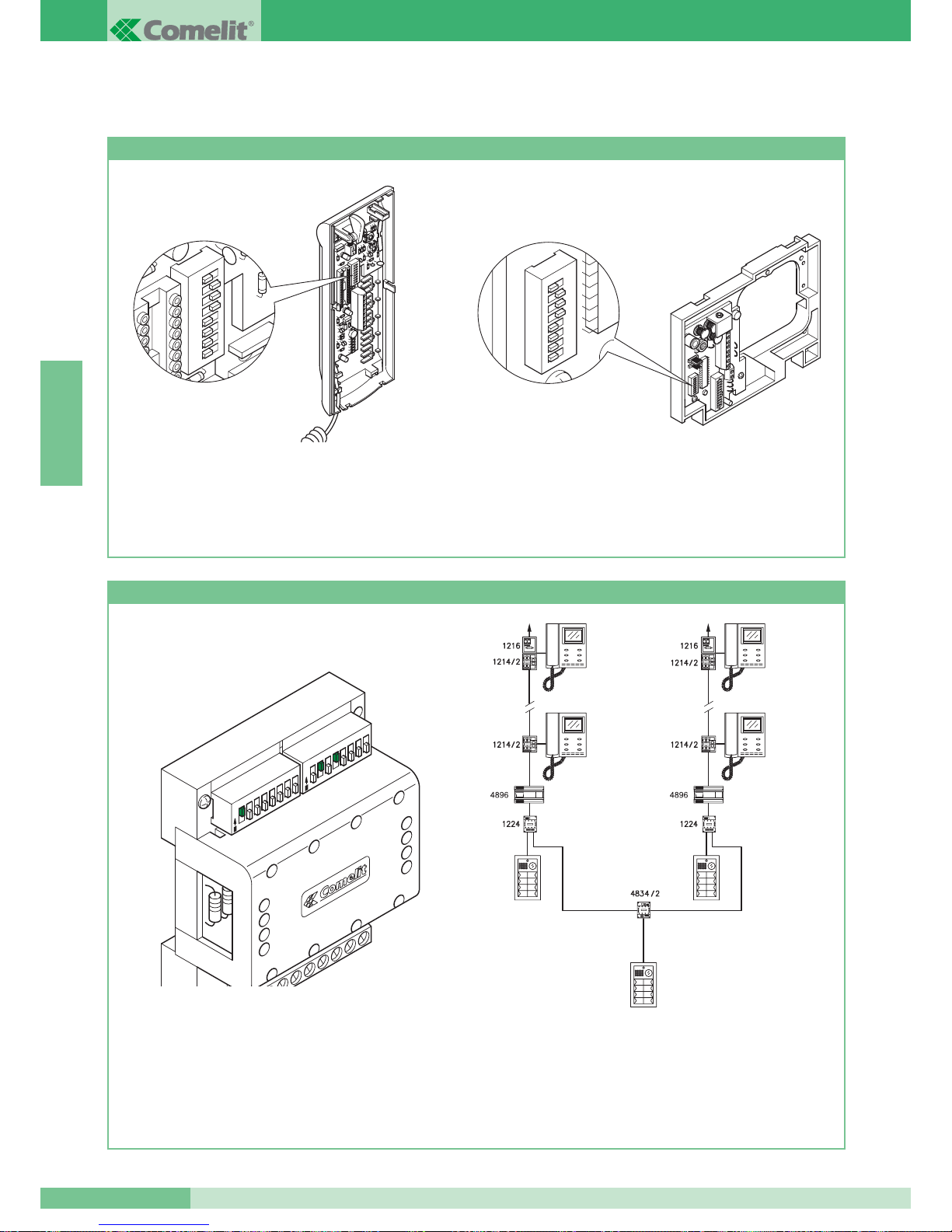
CONFIGURATION DES DISPOSITIFS
Programmation des combinés parlophoniques Art. 2408W/A, 2410W, 2428W et de la bride Art. 4714W/2
• Tous les combinés parlophoniques ou les brides du système
sont identifiés par un code propre qui doit être programmé
avec le dip switch présent sur la carte parlophonique ou sur
la bride (voir figures).
• Le code usager doit être programmé selon la correspondance
décrite dans le tableau de programmation de la page 63.
• Le codage peut être effectué à n’importe quel moment, même
en l’absence d’alimentation.
1 2
3
4 5
6 7
8
1 2
3
4 5
6 7
8
Programmation du commutateur Art. 1224
• Chaque module de commutation monte deux dip switches
à 8 sélecteurs (voir figure). Les deux dip switches définissent
la plage minimum MIN et maximum MAX des codes pouvant
être reconnus par le commutateur.
• N’oubliez pas que les dip switches MIN et MAX définissent
respectivement le code usager le plus bas et le code usager
le plus haut pouvant être branchés au montant.
• Pour programmer les valeurs désirées, se référer au tableau
de la page 63.
• Des commutations distinctes doivent gérer des intervalles
de codes non superposés.
PORTA PRINCIPALE DAL N° 1÷20.
SCALA A SCALA B
4700 W
4700 W/I
4701 W/A
4700 W
4700 W/I
4701 W/A
N° 1÷10 N° 11÷20
4700 W
4700 W/I
4701 W/A
4700 W
4700 W/I
4701 W/A
MAX
MIN
1
2
3
4
5
6
7
8
1
2
3
4
5
6
7
8
O
N
O
N
• Exemple de codage du commutateur Art. 1224 de l’escalier A
nombre minimum 1, nombre maximum 10.
GROUP S.P.A.
MT SB2 01
62
FRANÇAIS
ESCALIER A
N° 1÷10.
PORTE PRINCIPALE DU N° 1÷20.
ESCALIER B
N° 11÷20.
Page 64
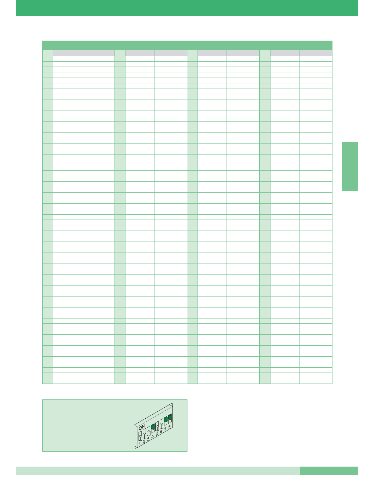
Tableau de programmation des dip switches
11 61 1,3,4,5,6 121 1,4,5,6,7 181 1,3,5,6,8
22 62 2,3,4,5,6 122 2,4,5,6,7 182 2,3,5,6,8
3 1,2 63 1,2,3,4,5,6 123 1,2,4,5,6,7 183 1,2,3,5,6,8
43 64 7 124 3,4,5,6,7 184 4,5,6,8
5 1,3 65 1,7 125 1,3,4,5,6,7 185 1,4,5,6,8
6 2,3 66 2,7 126 2,3,4,5,6,7 186 2,4,5,6,8
71,2,3 67 1,2,7 127 1,2,3,4,5,6,7 187 1,2,4,5,6,8
84 68 3,7 128 8 188 3,4,5,6,8
9 1,4 69 1,3,7 129 1,8 189 1,3,4,5,6,8
10 2,4 70 2,3,7 130 2,8 190 2,3,4,5,6,8
11 1,2,4 71 1,2,3,7 131 1,2,8 191 1,2,3,4,5,6,8
12 3,4 72 4,7 132 3,8 192 7,8
13 1,3,4 73 1,4,7 133 1,3,8 193 1,7,8
14 2,3,4 74 2,4,7 134 2,3,8 194 2,7,8
15 1,2,3,4 75 1,2,4,7 135 1,2,3,8 195 1,2,7,8
16 5 76 3,4,7 136 4,8 196 3,7,8
17 1,5 77 1,3,4,7 137 1,4,8 197 1,3,7,8
18 2,5 78 2,3,4,7 138 2,4,8 198 2,3,7,8
19 1,2,5 79 1,2,3,4,7 139 1,2,4,8 199 1,2,3,7,8
20 3,5 80 5,7 140 3,4,8 200 4,7,8
21 1,3,5 81 1,5,7 141 1,3,4,8 201 1,4,7,8
22 2,3,5 82 2,5,7 142 2,3,4,8 202 2,4,7,8
23 1,2,3,5 83 1,2,5,7 143 1,2,3,4,8 203 1,2,4,7,8
24 4,5 84 3,5,7 144 5,8 204 3,4,7,8
25 1,4,5 85 1,3,5,7 145 1,5,8 205 1,3,4,7,8
26 2,4,5 86 2,3,5,7 146 2,5,8 206 2,3,4,7,8
27 1,2,4,5 87 1,2,3,5,7 147 1,2,5,8 207 1,2,3,4,7,8
28 3,4,5 88 4,5,7 148 3,5,8 208 5,7,8
29 1,3,4,5 89 1,4,5,7 149 1,3,5,8 209 1,5,7,8
30 2,3,4,5 90 2,4,5,7 150 2,3,5,8 210 2,5,7,8
31 1,2,3,4,5 91 1,2,4,5,7 151 1,2,3,5,8 211 1,2,5,7,8
32 6 92 3,4,5,7 152 4,5,8 212 3,5,7,8
33 1,6 93 1,3,4,5,7 153 1,4,5,8 213 1,3,5,7,8
34 2,6 94 2,3,4,5,7 154 2,4,5,8 214 2,3,5,7,8
35 1,2,6 95 1,2,3,4,5,7 155 1,2,4,5,8 215 1,2,3,5,7,8
36 3,6 96 6,7 156 3,4,5,8 216 4,5,7,8
37 1,3,6 97 1,6,7 157 1,3,4,5,8 217 1,4,5,7,8
38 2,3,6 98 2,6,7 158 2,3,4,5,8 218 2,4,5,7,8
39 1,2,3,6 99 1,2,6,7 159 1,2,3,4,5,8 219 1,2,4,5,7,8
40 4,6 100 3,6,7 160 6,8 220 3,4,5,7,8
41 1,4,6 101 1,3,6,7 161 1,6,8 221 1,3,4,5,7,8
42 2,4,6 102 2,3,6,7 162 2,6,8 222 2,3,4,5,7,8
43 1,2,4,6 103 1,2,3,6,7 163 1,2,6,8 223 1,2,3,4,5,7,8
44 3,4,6 104 4,6,7 164 3,6,8 224 6,7,8
45 1,3,4,6 105 1,4,6,7 165 1,3,6,8 225 1,6,7,8
46 2,3,4,6 106 2,4,6,7 166 2,3,6,8 226 2,6,7,8
47 1,2,3,4,6 107 1,2,4,6,7 167 1,2,3,6,8 227 1,2,6,7,8
48 5,6 108 3,4,6,7 168 4,6,8 228 3,6,7,8
49 1,5,6 109 1,3,4,6,7 169 1,4,6,8 229 1,3,6,7,8
50 2,5,6 110 2,3,4,6,7 170 2,4,6,8 230 2,3,6,7,8
51 1,2,5,6 111 1,2,3,4,6,7 171 1,2,4,6,8 231 1,2,3,6,7,8
52 3,5,6 112 5,6,7 172 3,4,6,8 232 4,6,7,8
53 1,3,5,6 113 1,5,6,7 173 1,3,4,6,8 233 1,4,6,7,8
54 2,3,5,6 114 2,5,6,7 174 2,3,4,6,8 234 2,4,6,7,8
55 1,2,3,5,6 115 1,2,5,6,7 175 1,2,3,4,6,8 235 1,2,4,6,7,8
56 4,5,6 116 3,5,6,7 176 5,6,8 236 3,4,6,7,8
57 1,4,5,6 117 1,3,5,6,7 177 1,5,6,8 237 1,3,4,6,7,8
58 2,4,5,6 118 2,3,5,6,7 178 2,5,6,8 238 2,3,4,6,7,8
59 1,2,4,5,6 119 1,2,3,5,6,7 179 1,2,5,6,8 239 1,2,3,4,6,7,8
60 3,4,5,6 120 4,5,6,7 180 3,5,6,8
*240 5,6,7,8
*NOTE: le code 240 est réservé pour le standard.
EXEMPLE programmation code 200.
Code u.
Dip switches sur ON Nom usager
Code u.
Dip switches sur ON Nom usager
Code u.
Dip switches sur ON Nom usager
Code u.
Dip switches sur ON Nom usager
MT SB2 01
63
MT SB2 01
FRANÇAIS
Page 65
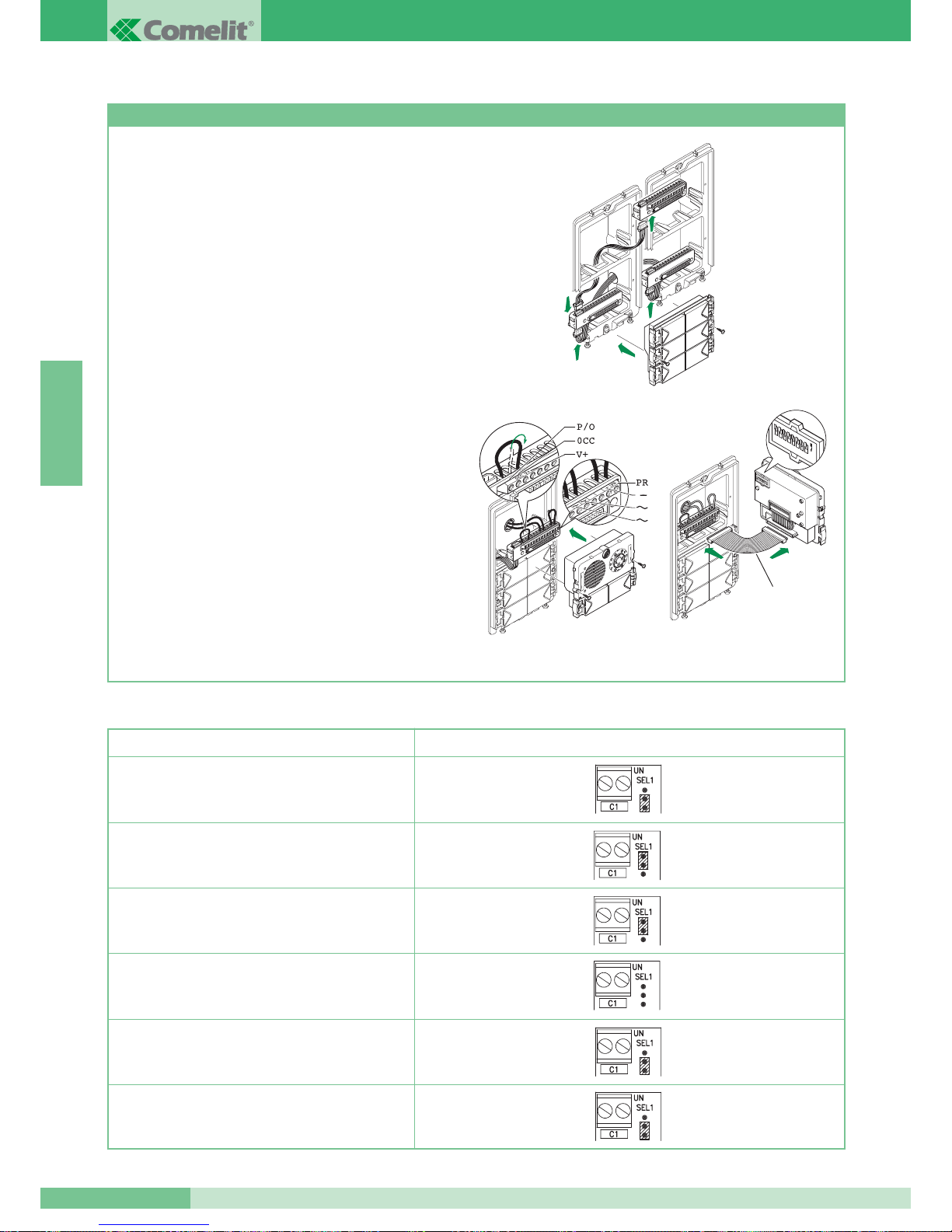
Programmation des boutons avec groupe audio Art. 1602 et vidéo Art. 4660 et modules Art. 3323/4 et 3323/6
1. Brancher les boîtes à bornes des modules Art. 3323/4 et
Art. 3323/6 entre elles et à la boîte à bornes du groupe
Art. 4660 ou Art. 1602 en utilisant les petits câbles spéciaux.
Introduire les modules Art. 3323/4 et Art. 3323/6 dans les
boîtes à bornes correspondantes (figure 1).
2. Sur la boîte à bornes du module Art. 4660 ou Art. 1602 brancher
l’alimentation à ~~ , brancher PR à – et déplacer P/O de OCC à
V+ (figure 2) en utilisant les jumpers présents sur cette même
boîte à bornes. Brancher la boîte à bornes au module Art. 4660
ou Art. 1602 assemblé de la manière précédemment indiquée.
(Attention, les modules Art. 3323/4 et Art. 3323/6 à programmer
doivent être déjà positionnés) (figure 2).
NOTE: Pour connecter la boîte à bornes au module Art. 4660 ou
Art. 1602, lors de la programmation on pourra utiliser le petit câble
Art. 3309 disponible comme accessoire en option (figure 3).
3. Programmer le dip switch placé sur le dos du module audio
avec le même code attribué au combiné parlophonique ou au
moniteur selon la correspondance décrite dans le tableau de
programmation à la page 63.
4. Appuyer sur le bouton que l’on désire associer à l’appel du
combiné parlophonique. La réalisation de la programmation est
signalée par un bip de confirmation.
5. A la fin de la programmation, replacer les jumpers dans leurs
positions initiales, PR sur PR et P/O sur OCC.
Programmation de la plaque de rue principale ou secondaire.
Les modules Art. 4660 et Art. 1602 fonctionnent normalement
comme plaque de rue principale (signal d’occupé temporisé).
Pour les programmer comme plaque de rue secondaire
(signal d’occupé actif pendant toute la durée où le montant
est occupé) tous les dip switches du sélecteur doivent être
placés sur ON.
Figure 1
Figure 3
Art. 3309
Figure 2
1
2
3
4
5
6
7
8
O
N
GROUP S.P.A.
MT SB2 01
64
Tableau des programmations de l’Art. 1216 en fonction du type de câble de connexion utilisé
Type de câble Programmation Art. 1216
Câble Comelit Art. 4577 sect. 1 mm
2
(Ø 12/10)
2
2
1
1
Câble bifilaire sect. 1,5 mm2 (Ø 14/10)
Câble tressé et blindé sect. 1 mm
2
(Ø 12/10)
Boucle téléphonique retorse sect. 0,28 mm
2
(Ø 6/10)
Câble UTP5 cat. 5 AWG 24 sect. 0,2 mm
2
(Ø 5/10)
Câble bifilaire sect. 0,5 mm2(Ø 8/10)
2
FRANÇAIS
Page 66
NOTES DE FONCTIONNEMENT
•A l’appui sur la touche d’appel, le visiteur actionne la sonnerie
du poste intérieur.
• La plaque de rue émet un bip indiquant que l’appel a eu lieu.
Lorsque, dans les installations à plusieurs entrées, le bip de
confirmation de l’appel n’est pas audible, c’est l’indice qu’une
autre conversation est en cours vers une autre plaque de rue
installée sur le même montant. En cas d’installation de l’Art. 3346,
module de signalisation d’installation occupée, attendre jusqu’au
débranchement du module avant de rappeler.
En cas d’installation de l’Art. 3340, l’indication d’occupé s’inscrit
à l’afficheur.
• Pour entrer en communication à partir du poste intérieur,
décrocher le bras du combiné téléphonique.
• La touche, marquée du symbole de la clé, agit sur la gâche
électrique de la plaque de rue en l’activant pendant environ
2 sec.
• Dans des installations visiophoniques, l’appui sur la touche
d’appel de la plaque de rue branche les leds à l’infrarouge
(non visibles à l’œil humain) pour éclairer la personne; l’image
demeure affichée à l’écran pendant environ 90 sec.
• Pour régler le volume du micro et celui de la sonnerie des
combinés parlophoniques, voir les pages 50 et 51.
• Pour régler le volume de la sonnerie des moniteurs,
voir les pages 46 et 47.
• Pour régler les volumes audio sur la plaque de rue voir la page 54.
• Pour valider la fonction de
Autoallumage, continuer à appuyer sur
le
bouton 2 pendant plus de 2 sec. (voir variante H page 111).
A la fin de la programmation un bip de confirmation est émis.
• Le Autoallumage du moniteur (si la fonction a été validée), a lieu
en appuyant sur le
bouton 2. En cas d’installation de deux
plaques de rue, l’appui à plusieurs reprises sur le bouton 2 de
Autoallumage du moniteur permet d’afficher l’image d’abord de
l’un, ensuite de l’autre, des deux plaques de rue (fonction de
bascule entre deux entrées).
• Pour varier la luminosité du moniteur, intervenir sur la molette de
réglage placée sur la partie inférieure.
• Pour varier le volume de la sonnerie d’appel intervenir sur le
déviateur gradué spécial placé sur la partie inférieure du moniteur.
• La carte en option Art. 4703 permet de programmer la fonction
Privacy. L’appui pendant plus de 2 sec. sur le bouton 4 du
moniteur branche la led signalant que la programmation du
moniteur en Privacy a eu lieu (voir variante I page 112). En
Privacy le moniteur ne sonne pas, il se branche et l’on a de toute
façon la possibilité de communiquer oralement avec la plaque de
rue après l’appel.
• Lorsqu’on raccroche le bras du combiné intérieur on dispose de
quelques secondes pour reprendre la conversation phonique avec
la plaque de rue.
Après avoir raccroché le bras, quelques secondes sont
nécessaires pour que l’image s’efface du moniteur.
• Le moniteur programmé comme
Principal (programmation
d’origine de la bride Art. 4714W/2) se branche à l’appel et au
Autoallumage, même s’il est branché comme moniteur additionnel
avec le même code usager.
• Le moniteur programmé comme
Secondaire (voir variante
SB2/A1-A2) ne se branche pas à l’appel mais il peut être branché
en appuyant sur le bouton 2 (fonction demande vidéo). Dans ce
cas, le Autoallumage du moniteur ne peut pas être effectué. A
remarquer la différence entre le Autoallumage, c’est-à-dire le
branchement du moniteur lorsque l’installation est libre, avec la
possibilité de faire basculer l’image entre deux plaques de rue et
la demande vidéo active seulement après l’appel.
• Les moniteurs et les combinés parlophoniques ayant le même
code utilisateur retentissent tous en même temps
(indépendamment qu’ils soient principaux ou secondaires)
à l’appel de la plaque de rue et à celui du palier.
MT SB2 01
65
MT SB2 01
FRANÇAIS
Page 67

Page 68
INHOUD
•
ALGEMENE INFORMATIE pag. 68
•
WAARSCHUWINGEN pag. 68
•
MONITOREN pag. 68
•
DEURTELEFOONS pag. 72
•
ENTREEPANELEN pag. 73
•
VOEDINGEN EN ACCESSOIRES pag. 78
•
INSTALLATIEVOORSCHRIFTEN pag. 81
•
CONFIGURATIE VAN DE APPARATUUR pag. 84
•
WERKING pag. 87
•
AANSLUITSCHEMA’S pag. 88
•
VARIANTEN VAN DE STANDAARD
AANSLUITSCHEMA’S pag. 98
Simplebus2 Systeem
MT SB2 01
67
MT SB2 01
NEDERLANDS
Page 69
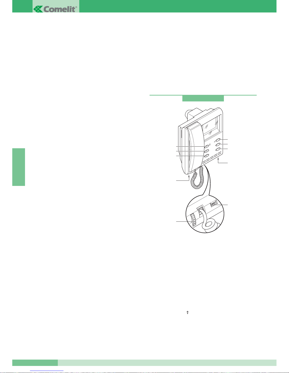
ALGEMENE INFORMATIE
Het kenmerk van het “Simplebus2” systeem is de eenvoudige
installatie met slechts 2 omkeerbare aders voor de hele installatie.
Hierdoor zijn geen plaatselijke voedingen meer nodig, of een
centrale voeding met extra aders in de installatie.
Deze 2-draads technologie biedt het voordeel dat het aantal
draden altijd voldoende is voor het aansluiten van het maximum
aan binnentoestellen, of dit nu een audio systeem is of een
audio/video systeem. Een gewoon deurtelefoontoestel kan direct
vervangen worden door een videofoon toestel.
Wanneer dit systeem gecombineerd wordt met de “Powercom”
entreepanelen, welke zeer eenvoudig te monteren zijn door de
modulaire opbouw, worden mogelijke installatiefouten tot een
minimum beperkt en zal een drastische tijdbesparing het gevolg zijn.
Bovendien is er een breed assortiment accessoires beschikbaar
om aan alle eisen te kunnen voldoen.
Het systeem is uit te breiden tot maximaal 240 gebruikers,
waarbij er maximaal 3 toestellen bij één gebruiker geïnstalleerd
kunnen worden.
Het systeem wordt standaard met deuropeningfunctie,
portiersoproep / vrije drukknop en beeldoproep geleverd.
Eveneens is het mogelijk optionele kaarten te installeren voor
bijzondere toepassingen (bijv. LED, extra knoppen).
Voor de complete omschrijving van de artikelen met betrekking tot
de Simplebus2 installatie wordt verwezen naar de Catalogus 66.
WAARSCHUWINGEN
Volg nauwkeurig de door de fabrikant geleverde aanwijzingen.
Alle apparaten van de installatie mogen uitsluitend gebruikt
worden voor het doeleinde waarvoor ze ontworpen zijn.
COMELIT GROUP S.p.A. acht zich niet aansprakelijk voor een
onjuist gebruik van de apparaten, door anderen aangebrachte
wijzigingen voor wat voor doeleinde dan ook en het gebruik van
niet originele accessoires en materiaal.
Installeer het systeem in overeenstemming met de geldende normen.
Alle producten zijn in overeenstemming met de voorschriften van
de richtlijnen CEE 73/23-89/336 en dit wordt aangetoond door het
CE keurmerk op de apparaten.
Plaats de bedrading van de stamleiding niet in de buurt van
voedingskabels (220/380V).
Waarschuwingen voor de gebruiker
Als er iets aan de installatie defect mocht gaan of niet goed mocht
werken, wend u dan uitsluitend tot de installateur of tot
vakbekwaam personeel.
MONITOREN
Veiligheidsvoorschriften
Ter voorkoming of afname van het risico voor storingen en
elektrische schokken:
• het deksel niet verwijderen en niets eigenhandig repareren. Als het
nodig mocht zijn, de hulp inroepen van vakbekwaam personeel.
• Geen voorwerpen in het apparaat steken en geen vloeistof
in gieten.
• Sluit de luchtcirculatie niet af door de speciale sleuven te bedekken.
Halfinbouwmonitor serie Videocom (korte buis)
Technische gegevens:
Monitor van de serie Videocom met afmetingen 193x223x65 mm,
gedeeltelijk ingebouwd (49mm diep in de muur), wit (RAL9010) met Z/W
4.5” scherm. Kan geïnstalleerd worden op de inbouwdoos art. 4514 maar
ook op de inbouwdozen geschikt voor 3 DIN modulen art. 4517, zie pag.
71. Te completeren met aansluitgrondplaat art. 4714W/2.
De monitor is compleet met:
1. Bevestigingshaken op de grondplaat.
2. Afstelling van de helderheid (draaien om de lichtsterkte te
veranderen).
3. Afstelling van het belvolume (naar links schuiven om het
volume te verhogen).
4. Deuropeningsknop
().
5. Knop om de centrale te bellen / vrij (1).
6. Knop voor beeldoproep / passieve beeldoproep (2).
7. Knop voor digitale functies* (3).
8. Privacy knop* (4).
9. LED* (0).
* alleen beschikbaar met optionele kaart art. 4703W.
art. 4700W
1
2
4
3
4
5
6
9
1
3
2
1
8
7
NEDERLANDS
GROUP S.P.A.
MT SB2 01
68
Page 70
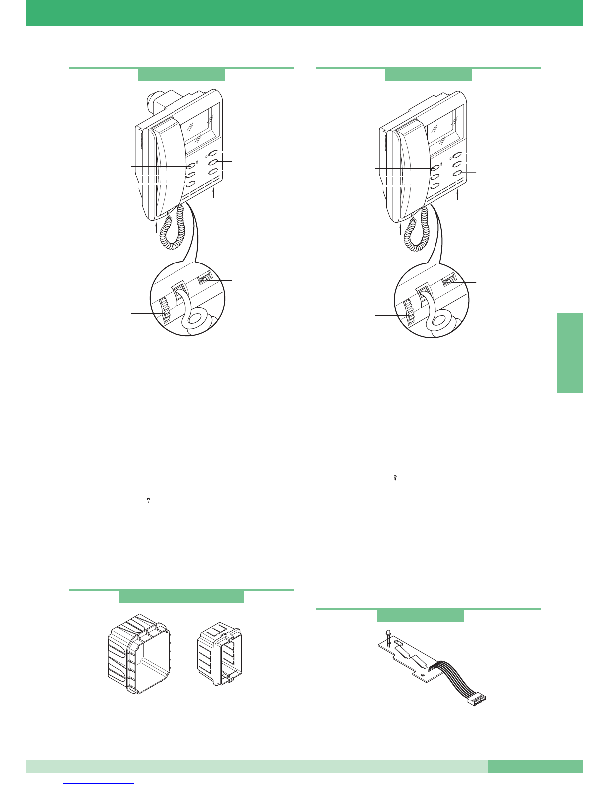
Halfinbouwmonitor serie Videocom (lange buis)
Technische gegevens:
Monitor van de serie Videocom met afmetingen 193x223x65 mm,
ingebouwd (68 mm diep in de muur), wit (RAL9010) met Z/W 4.5”
direct-vision. Kan alleen geïnstalleerd worden op de inbouwdoos
art. 4514, zie pag. 71.
Te completeren met grondplaat art. 4714W/2.
De monitor is compleet met:
1. Bevestigingshaken op de grondplaat.
2. Afstelling van de helderheid (draaien om de lichtsterkte te
veranderen).
3. Afstelling van het belvolume (naar links schuiven om het volume
te verhogen).
4. Deuropeningsknop
().
5. Knop om de centrale te bellen / vrij (1).
6. Knop voor beeldoproep / verzoek om video (2).
7. Knop voor actuator * (3).
8. Privacy knop * (4).
9. LED * (0).
* alleen beschikbaar met optionele kaart art. 4703W.
art. 4514 inbouwdoos monitor art. 4700W en art. 4700W/I.
art. 4517 doos burgerlijke serie 3 DIN modulen bruikbaar voor
inbouw monitor art. 4700W.
Wandmonitor serie Videocom
Technische gegevens:
Monitor van de serie Videocom met afmetingen 193x223x65, voor
aan de wand, wit RAL9010 met B/W 4.5” direct-zicht-scherm.
Te completeren met aansluitgrondplaat art. 4714W/2.
De monitor is compleet met:
1. Bevestigingshaken aan de aansluitgrondplaat.
2. Afstelling van de helderheid (draaien om de lichtsterkte te
veranderen).
3. Afstelling van het belvolume (naar links verplaatsen om het
volume te verhogen).
4. Deuropeningsknop
()
.
5. Knop om de centrale te bellen / vrij (1).
6. Knop voor beeldoproep / verzoek om video (2).
7. Knop voor actuator * (3).
8. Privacy knop * (4).
9. LED * (0).
* alleen beschikbaar met optionele kaart art. 4703W.
Het gebruik van de monitor Videocom oude serie 4701W kan
problemen in de werking geven.
art. 4700W/I
1
2
4
3
4
5
6
9
1
3
2
1
8
7
art. 4701W/A
1
2
4
3
4
5
6
1
3
2
1
9
8
7
art. 4514W en art. 4517
Kaart extra knoppen en LED
Optionele kaart met twee extra knoppen en signalerings LED.
Kunnen in alle monitors van de serie Videocom aangebracht worden.
art. 4703
MT SB2 01
69
MT SB2 01
NEDERLANDS
Page 71
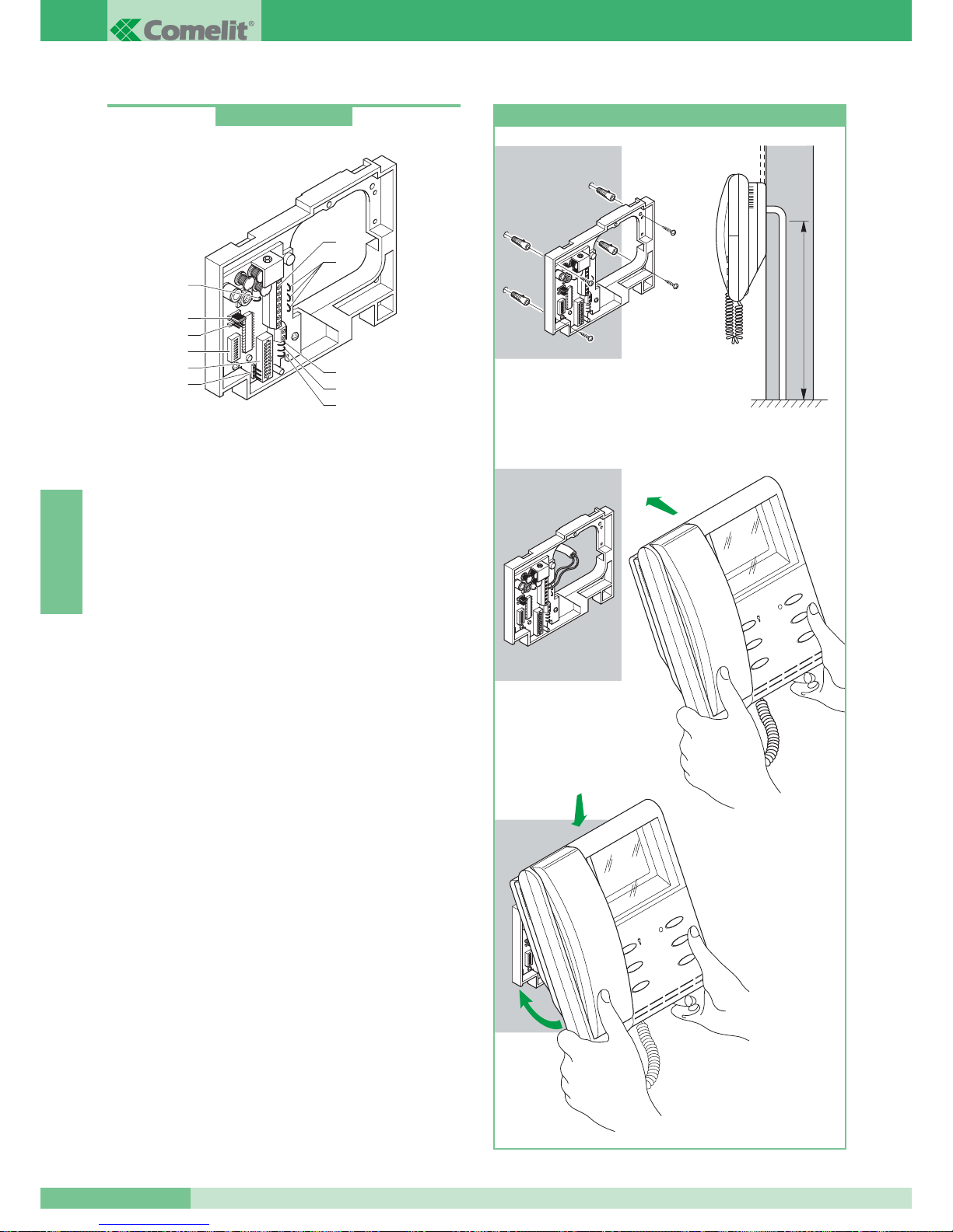
Simplebus2 grondplaat
Grondplaat van de monitor voor de installatie van de monitor aan
de muur of door middel van bureausteun art. 4712W (zie pag. 71)
en maakt de aansluiting van de kabels van de installatie mogelijk.
Voorzien van klemmen voor de aansluiting van de verdiepingsoproep
(zie variant G pag. 111, voor de verbinding van een extra bel (zie
SB2/D pag. 105) en voor het gebruik van de knop 1 van de monitor
voor verschillend gebruik (zie variant E pag. 110).
Er kunnen maximaal 3 grondplaten met dezelfde gebruikerscode in
een installatie gemonteerd worden (zie pag. 98).
Compatibel met Simplebus1 installaties.
Technische gegevens:
Afmetingen: 158x121x24 mm.
1. Connector voor de monitor.
2. Aansluitingen op de klemmen:
0 +20V aansluiting art. 1212/B.
L L aansluiting buslijn.
CFP CFP Ingang voor etagebel drukknop
P1 C1 Voor een potentiaal vrij contact,
knip de bruggen CV3 en CV4 door.
S+ S- uitgang voor extra bel.
3. CV5 Brug voor afsluiten videosignaal
4. JP1 jumper voor activering van passieve beeldoproep bij
secundaire monitoren(zie variant F pag. 110).
5. CN2 steker voor programmering.
6. Dipswitches voor het programmeren van de gebruikerscode.
7. CV2, CV1, CV7 draadbruggen om extra monitoren te voeden
door middel van art.1212/B (zie variant SB2/A3 pag. 101).
8. CV3, CV4 draadbruggen om knop 1 potentieel vrij te maken.
9. CV6 draadbrug voor de keuze van het systeem (Simplebus2 of
Simplebus1).
10. JP2 jumper voor de keuze van het systeem (Simplebus2 of
Simplebus1).
art. 4714W/2
7
1
6
4
5
2
8
9
8
3
10
147
cm
1
2
3
4
1
2
1
2
3
4
Installatie wandmonitor art. 4701W/A
GROUP S.P.A.
MT SB2 01
70
NEDERLANDS
Page 72
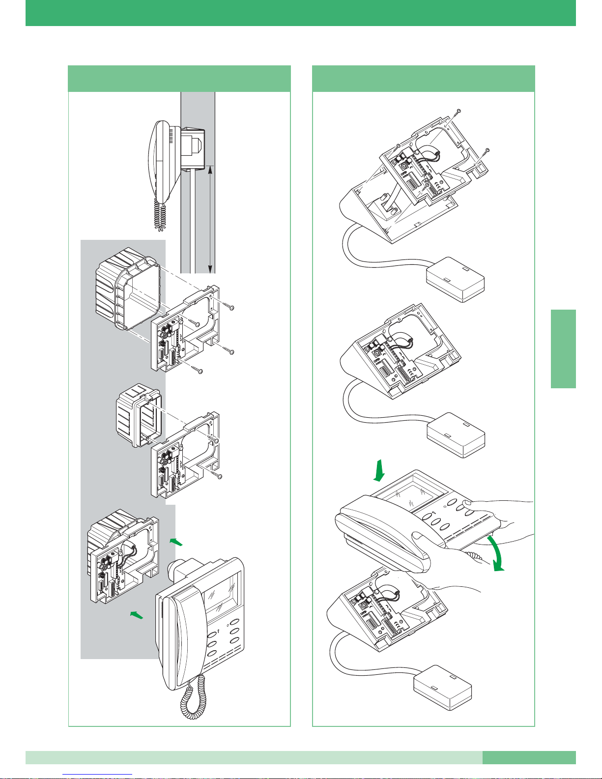
145
cm
1
2
4
3
Art. 4514
Art. 4517
solo per monitor
Art. 4700W
Art.
4700W
4700W/I
Per monitor
Installatie wandmonitor
art. 4700W en art. 4700W/I
2
1
4
3
1
2
Installatie van bureausteun art. 4712W
voor monitor art. 4701W/A en art. 4700W
MT SB2 01
71
MT SB2 01
NEDERLANDS
Voor monitor
art.
4700W
4700W/I
Alleen voor
monitor
art. 4700W
art. 4514
art. 4517
Page 73
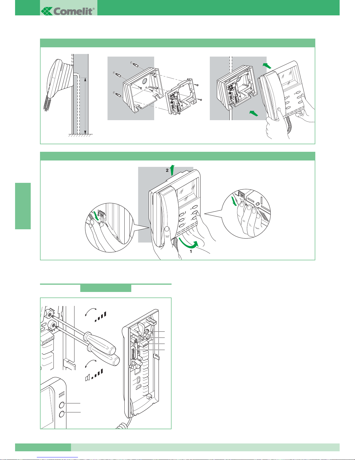
DEURTELEFOONS
Deurtelefoon
Deurtelefoon van de serie Okay met afmetingen 85x223x65 mm.
Voorzien van deuropeningsknop en knop om naar portiercentrale te
bellen of voor het activeren van een speciaal relais (zie variant A
pag. 108). Standaard uitgerust met verdiepingsoproep (zie variant B
pag. 108). Er kunnen maximaal 3 deurtelefoons met dezelfde
gebruikerscode in één installatie geïnstalleerd worden. Voor het
instellen van de gebruikerscode zie “Programmering deurtelefoon
art. 2408W/A, 2428W en grondplaat art. 4714W/2” op pag. 84.
Alleen te gebruiken voor audio installaties.
Technische gegevens:
1. Deuropeningsknop.
2. Knop voor het bellen naar de portierscentrale/ drukknop voor
verschillende doeleinden (aansluitingen AB).
3. Aansluitingen op de klemmen:
L L aansluiting buslijn.
CFP CFP ingang etagebel.
AB Aansluitingen drukknop voor diverse doeleinden.
Voor een potentieelvrij NO contact, de draadbruggen CV1 en CV2
doorknippen.
4. Dipswitches voor het instellen van de gebruikerscode (zie pag. 85).
5. Trimmer voor het afstellen van het volume van de microfoon.
6. Trimmer voor het afstellen van het volume van de bel.
147 cm
Art. 4704
1
2
4
3
Art. 4700W
1
2
+
-
+
-
MIC
5
6
3
4
Installatie halfinbouwmonitor art. 4700W met opbouwhuis art. 4704
Hoe de monitor te verwijderen
art. 2408W/A
GROUP S.P.A.
MT SB2 01
72
NEDERLANDS
Page 74
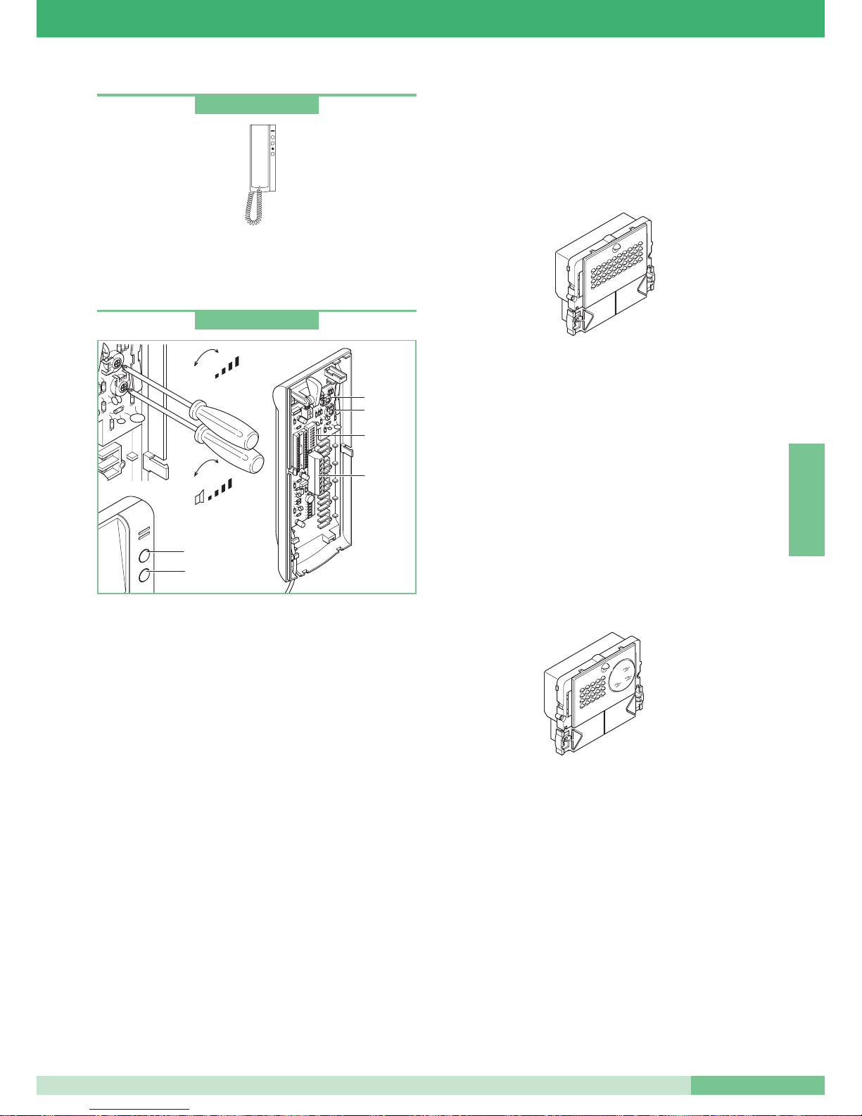
Deurtelefoon
Deurtelefoon net als art. 2408W/A met extra LED en schakelaar
voor
Privacy of Dokter service (automatische opening van de deur
na aanbellen). Zie technisch blad van het artikel voor de aansluiting
op de installatie.
Deurtelefoon
Deurtelefoon van de serie Okay met afmetingen 85x223x65 mm.
Voorzien van deuropeningsknop en een drukknop voor de oproep
van de portierscentrale of een andere functie (zie variant C pag. 109).
Standaard uitgerust met etagebel (zie variant D pag. 109) en extra bel
(zie SB2/D pag. 105).
Deurtelefoon te gebruiken in gemixte audio-video installaties met
voedingsmixer art. 4896 of in audio installaties wanneer er een extra
bel nodig is. Er kunnen maximaal 3 deurtelefoons met dezelfde
gebruikerscode in één systeem geïnstalleerd worden. Voor het
installeren van extra deurtelefoons met dezelfde gebruikerscode zie
de varianten SB2/A4 en SB2/A5 op pag. 102. Voor het instellen van
de gebruikerscode zie “Programmering deurtelefoon art. 2408W/A,
2428W en grondplaat art. 4714W/2” op pag. 84.
Technische gegevens:
1. Deuropeningsknop.
2. Knop voor het bellen naar de portierscentrale/ drukknop voor
verschillende doeleinden (aansluitingen P1 C1).
3. Aansluitingen op de klemmen:
L L aansluiting buslijn.
CFP CFP ingang etagebel.
P1 C1
Aansluitingen drukknop voor diverse doeleinden. Voor een
potentieelvrij NO contact, de draadbruggen CV2 en CV3 doorknippen.
S+ S- aansluitingen voor een extra bel.
4. Dipswitches voor het instellen van de gebruikerscode (zie pag. 85).
5. Trimmer voor het afstellen van het volume van de microfoon.
6. Trimmer voor het afstellen van het volume van de bel.
5
6
1
2
4
3
+
-
+
-
MIC
art. 2410W
art. 2428W
ENTREEPANELEN
In Simplebus2 installaties kunnen entreepanelen van de serie
Powercom, Vandalcom en Logicom gebruikt worden. Voor
Vandalcom en Logicom wordt er verwezen naar het technisch blad
FT/SB/01 en naar de Catalogus 50.
Audio luidsprekerunit Serie Powercom
Bestaat uit art. 3320 + art. 1602.
Luidsprekerunits met aansluitblok en dubbele versterker,
waterdichte luidspreker en electretmicrofoon. Het volume van de
microfoon en van de luidspreker kan zowel vanaf de voorkant als
vanaf de achterkant geregeld worden bij art.1602 (zie pag. 76). De
microfoon kan verplaatst worden om het akoestisch rendement te
verbeteren (zie pag. 76).
Beldrukker van aluminiumlegering met naamplaatjes die er vanaf
de voorkant uitgenomen kunnen worden.
Compleet met microprocessor en dipswitches met 8 standen voor
de programmering van de drukknoppen voor de gebruikers.
Voor het programmeren van de drukknoppen zie pag. 86.
Voeding 12V AC (gebruik art. 1195).
Deuropeningsfunctie door middel van elektronische switch
(3A alleen wisselstroom). Afmetingen 112x89.5x40 mm.
Video luidsprekerunit Serie Powercom
Bestaat uit art. 3321 + art. 4660.
Verstelbare pinhole high sensitivity CCD 1/4” Z/W camera.
Infraroodverlichting (6 LED’S). Compleet met aansluitblok en
luidsprekerunit met dubbele versterker, waterdichte luidspreker en
electretmicrofoon. Het volume van de microfoon en van de
luidspreker kan zowel vanaf de voorkant als vanaf de achterkant
geregeld worden bij art. 4660 (zie pag. 76).
De microfoon kan verplaatst worden om het akoestisch rendement te
verbeteren (zie pag. 76).
Beldrukker van aluminiumlegering met naamplaatjes die er vanaf de
voorkant uitgenomen kunnen worden.
Compleet met microprocessor en dipswitches met 8 standen voor de
programmering van de drukknoppen voor de gebruikers.
Voor het programmeren van de drukknoppen zie pag. 86. Voeding
12V AC (gebruik art. 1195).
Deuropeningsfunctie door middel van elektronische switch (3A alleen
wisselstroom). Afmetingen 112x89.5x40 mm.
MT SB2 01
73
MT SB2 01
NEDERLANDS
Page 75
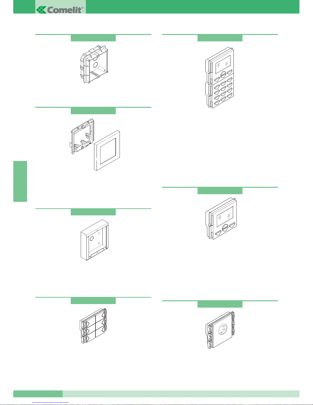
Inbouwdozen
Beschikbaar voor 1, 2 en 3 modulen.
Afmetingen enkele module 127x127x45 mm.
Bezetmodule
Systeem bezet module. Compleet met een blauwe knipper LED
voor het aangeven van de bezet status. Wordt geleverd met een
blanco label, zodat een eigen tekst kan worden toegevoegd.
Afmetingen: 112x89.5x38 mm
Digitale oproep module met naamindex
Uitgevoerd met grafische LCD 128x64 dots, toetsenbord met 16
verlichte drukknoppen met blauwe LED. Er is ook een codeslot
functie ingebouwd. Het is compleet met naamindex, welke 400
gebruikersnamen kan opslaan. Om een naam op te zoeken kan
worden gescrolled d.m.v. 2 drukknoppen, of door het invoeren van
de eerste letters. Ook kan direct de gebruikerscode worden
ingetoetst. Als de juiste naam op het display verschijnt, kan
eenvoudig op de beltoets gedrukt worden. Het programmeren is
eenvoudig door het gebruik van een afstandbediening art. 1230 of
met de software voor PC art. 1249. Afmetingen 112x180x40 mm.
Naam index module
Elektronische namenlijst met grafische display 128x64 dots. Kan
maximaal 400 gebruikersnamen opslaan. Om een naam op te
zoeken kan worden gescrolled d.m.v. 2 drukknoppen. Als de juiste
naam op het display verschijnt, kan eenvoudig op de beltoets
gedrukt worden. Het programmeren is eenvoudig door het gebruik
van een afstandbediening art. 1230 of met de software voor PC
art. 1249. Afmetingen: 112x89.5x40 mm.
Drukknopmodulen
Beldrukker module uitgevoerd met microswitches en vervaardigd
van een chroomaluminium legering. Blauwe LED voor de
verlichting van de uitneembare naamkaders. Leverbaar met 4 of 6
drukknoppen. Afmetingen 112x89.5x40 mm. Voor het programmeren
van de knoppen zie pag. 86.
art. 3110
art. 3323
art. 3342
art. 3346
art. 3340
art. 3311
art. 3316
Moduulframes compleet met sierrand
Het frame is gemaakt van gegoten aluminium en door een speciale
coating geschikt voor buitengebruik.
Beschikbaar voor 1, 2 en 3 modulen in de kleuren grijs, wit, blauw
en oranje. Afmetingen van de enkele module 125x125x15.5 mm.
Opbouw behuizingen
Behuizing van RVS. Beschikbaar voor 1, 2, 3, 4, 6 en 9 modulen.
Voor bevestiging aan de wand, ook buiten. Handig als het niet
mogelijk is de doos in te bouwen. Afmetingen van de enkele
module 123x123x32.5 mm.
GROUP S.P.A.
MT SB2 01
74
NEDERLANDS
Page 76
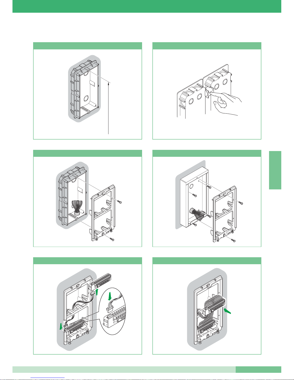
Aanwijzingen voor het installeren van de audio en video entreepanelen
160 - 165 cm
Hoogte inbouwdoos Hoe meerdere dozen naast elkaar te plaatsen
Bevestiging van het frame op de inbouwdoos
Bevestiging van het frame op de opbouw behuizing
Aansluiting 4-polige kabel
Aansluitblok plaatsen of verwijderen
MT SB2 01
75
MT SB2 01
NEDERLANDS
Page 77
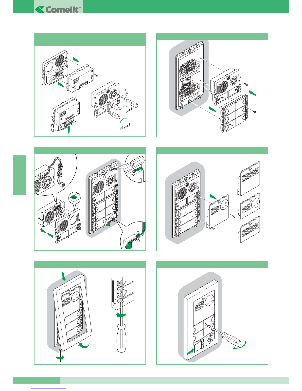
1
2
3
360˚
+
-
+
-
MIC
Montage, aansluitingen en afstellingen
audio-video systeem
Aanbrengen van de modulen
2
3
5
1
4
Andere positie van de microfoon
Montage / Demontage voorpanelen
Bevestiging sierrand
C
arla
R
ossi
Aanbrengen / verwijderen naamkaartjes
open
close
GROUP S.P.A.
MT SB2 01
76
NEDERLANDS
Page 78
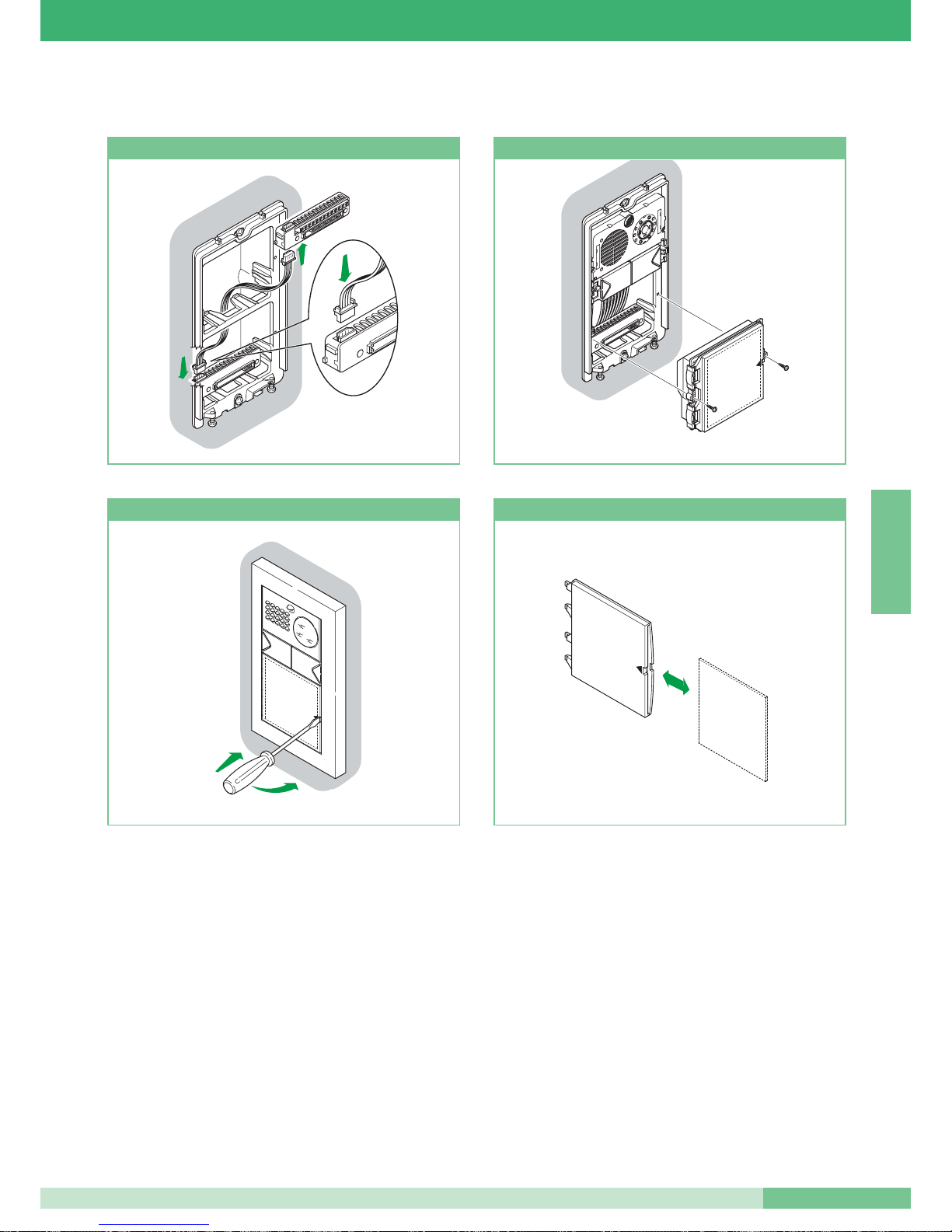
Aansluiting 4-polige kabel
10
Aanbrengen van de module
2
1
10
Verwijdering kaartjeshouder
15
Kaartje aanbrengen/verwijderen
Montage-instructies informatieve modulen art. 3326, art. 3344 en art. 3346
MT SB2 01
77
MT SB2 01
NEDERLANDS
Page 79
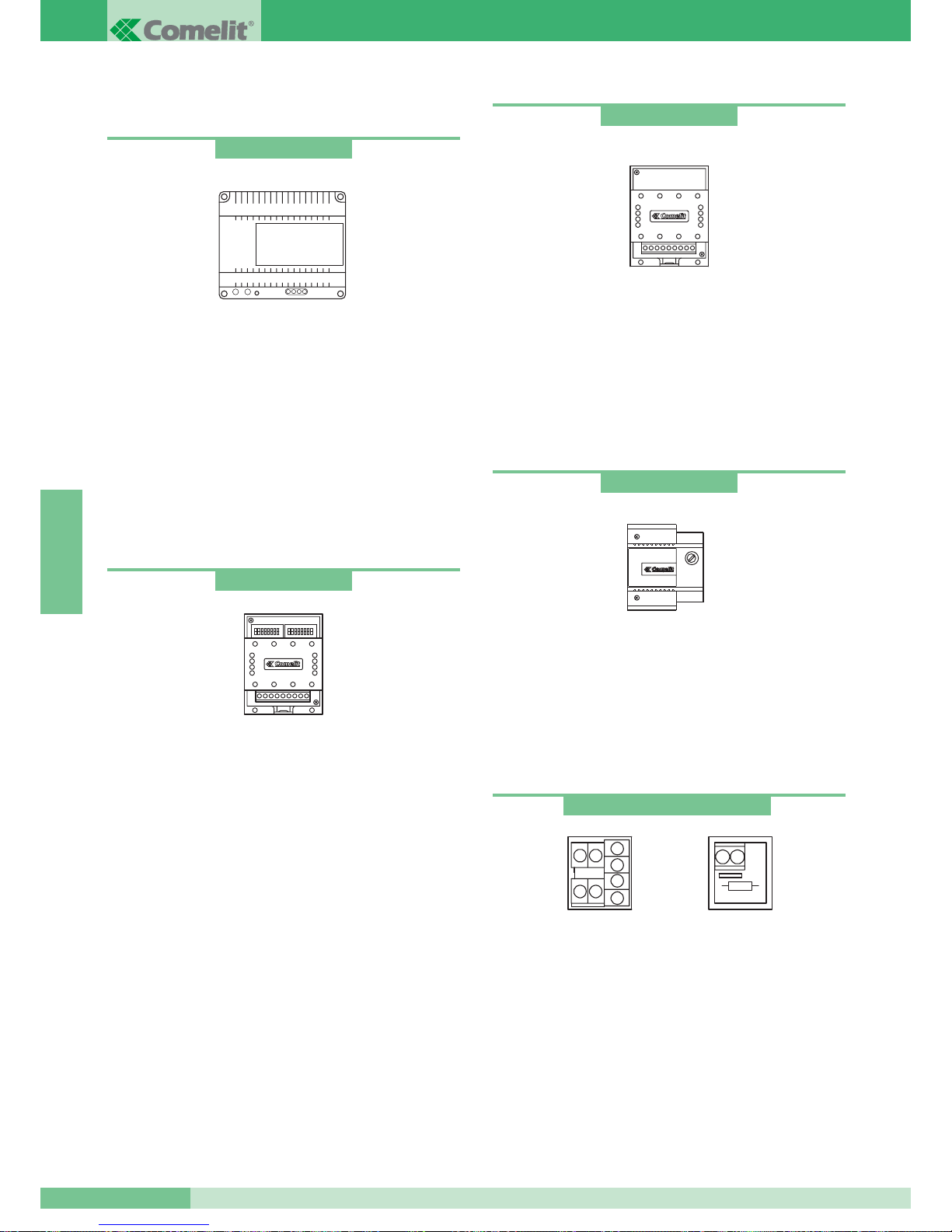
VOEDINGEN EN ACCESSOIRES
Transformator voor voedingsmixer
Transformator 65VA. (T 1’on / 5’off).
Primair: 230VAC
Secundair: OUT1: 36VAC 1.5A
OUT2: 14VAC 1A
De transformator is uitgerust met interne PTC beveiliging.
Afmetingen: 107x90x60 (8 DIN modulen).
Deurselector
Voeding 12VAC.
Afmetingen 66x85x35mm (4 DIN modulen).
Aansluitklemmen:
~ ~ * voeding 12VAC-20VDC.
LS LS ingang buslijn secundaire buitenapparatuur.
LP LP ingang buslijn primair entreepaneel.
LM LM uitgang buslijn stamleiding.
Voor het programmeren van de deurselector zie pag. 84.
Voeding voor extra monitor
Voeding 15VA
Input: 230VAC
Output: 0- 20VDC 700mA
De transformator is uitgerust met interne PTC beveiliging.
Afmetingen: 87x105x65 (5 DIN modulen).
art. 1246
Aftakblok en Afsluitblok
Zie pag. 86 voor de configuratie van art. 1216 i.c.m. de gebruikte
kabel. Aansluitklemmen:
Lin Lin: ingang stamleiding.
Lout Lout: uitgang stamleiding.
LM LM: Aftakking naar de monitor/deurtelefoon.
+ +: klemmen voor aansluiting voeding voor compatibiliteit
met Simplebus1 installaties.
art. 1212/B
Relais
Relais 12-24V DC-AC 5A voor algemeen gebruik.
Direct aanstuurbaar vanaf de extra
beluitgang van de grondplaat art. 4714W/2 of deurtelefoon
art. 2428W. Afmetingen: 66x85x35 mm (4 DIN modulen).
Aansluitklemmen:
+ - voeding relais.
C-NO-NC contacten relais.
art. 1122/A
art. 1214/2 en art. 1216
art. 1214/2
art. 1216
art. 1224
GROUP S.P.A.
MT SB2 01
78
NEDERLANDS
Page 80
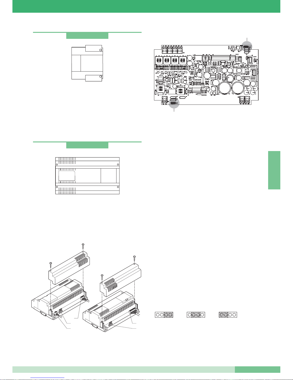
Transformator
Transformator 60VA
Primair 230VAC
Secundair: OUT1: 0-12V 1.5A
OUT2: 0-12V 1.5A
De transformator is uitgerust met interne zekering.
Afmetingen: 87x105x65 (5 DIN modulen).
Voedingsmixer
De voedingsmixer art. 4896 bevindt zich in een behuizing van 12
DIN modulen. Afmetingen: 208x140x65 mm.
Om toegang te kunnen verkrijgen tot de aansluitklemmen: de
zijdeksels verwijderen zoals in de afbeelding getoond wordt.
art. 4896
art. 1195
4
1
3
4
2
JP1
JP2
Art. 4896 moet gevoed worden door middel van transformator
art.1246. Maak de aansluitingen van de installatie met
uitgeschakelde stroom.
Daar hij voorzien is van PTC beveiliging moet u, na een
kortsluiting, de stroom er ongeveer een minuut lang af halen om
hem weer te activeren.
Schakel eerst het entreepaneel in en zet daarna spanning op de
voedingsmixer art. 4896.
Met deze voedingsmixer kan maximaal één monitor tegelijk gevoed
worden en is in staat
MAX 100 gebruikers te beheren.
Aansluitklemmen:
1.
Lin Lin aansluiting op de lijn afkomstig van entreepanele(e)l(en).
2. 0V 36V aansluiting op de klemmen OUT1 van de transformator
art. 1246.
0V 14V aansluiting op de klemmen OUT2 van de transformator
art. 1246.
3.
L1 L1 uitgang stamleiding 1.
L2 L2 uitgang stamleiding 2.
L3 L3 uitgang stamleiding 3.
L4 L4 uitgang stamleiding 4.
4. Jumpers in te stellen naar gelang het totaal aantal gebruikers
aangesloten op de voedingsmixer art. 4896.
JP1 en JP2 in
positie 3 voor installaties met van 0 tot 15
gebruikers.
JP1 en JP2 in
positie 2 voor installaties met van 16 tot 35
gebruikers.
JP1 en JP2 in positie 1 voor installaties met van 36 tot 100
gebruikers.
JP1 - JP2
2
3
1
MT SB2 01
79
MT SB2 01
NEDERLANDS
Page 81
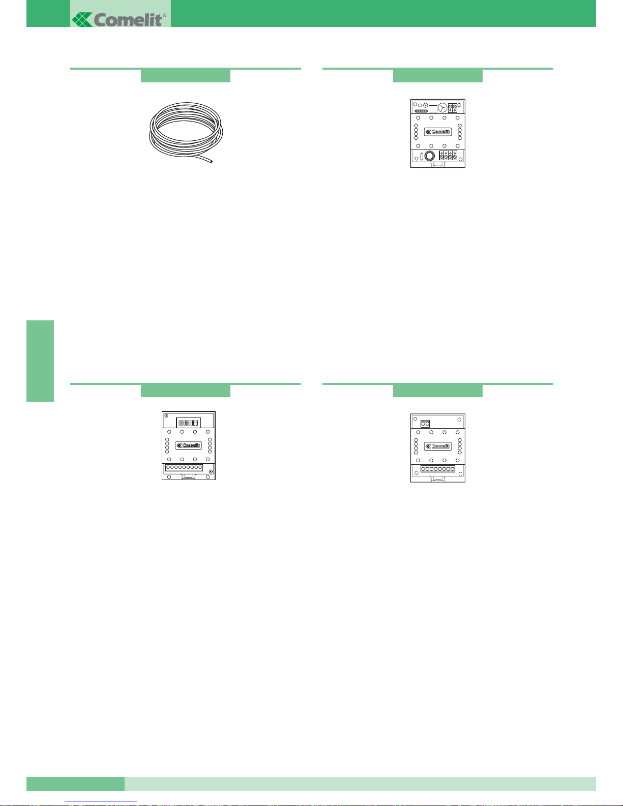
Buslijnversterker
Versterker voor Simplebus1 video-installaties.
Regenereert het videosignaal van de buslijn.
Voeding: 12V AC of 20V DC.
Alleen te monteren in de installatie vóór de voedingsmixer.
Afmetingen: 66x85x35 mm (4 DIN modulen).
Aansluitklemmen:
Lin Lin: ingang stamleiding.
Lout Lout: uitgang stamleiding.
~+ ~-: voeding module.
art. 4833/A
Buslijnverdeler
Verdeler voor Simplebus video-installatie.
Maakt het mogelijk het signaal naar 4 buslijnen te verdelen.
Alleen installeren in de installatie vóór de voedingsmixer.
Afmetingen: 66x85x35 mm (4 DIN modulen).
Aansluitklemmen:
Lin Lin: ingang buslijn.
L1 L1: uitgang buslijn 1.
L2 L2: uitgang buslijn 2.
L3 L3: uitgang buslijn 3
(weerstand afknippen alvorens de draad aan te brengen).
L4 L4: uitgang buslijn 4
(weerstand afknippen alvorens de draad aan te brengen).
art. 4834/2
Comelit Simplebus2 kabel
Speciale kabel voor Simplebus2 installaties: bestaat uit een rode
en zwarte getwiste ader 1 mm
2
.
Leverbaar in rollen van 100 m. en haspels van 500 m.
Relais voor verschillende toepassingen
Voeding 12VAC, 20VDC.
Vermogen relais: 10A.
Dit relais kan worden toegepast voor:
• Extra bel.
• Aansturing relais door gebruiker in installaties zonder portiercentrale.
• Verlichting trappenhuis.
• Secundaire deuropener.
Voor installatie en verschillende varianten zie documentatie van
art. 1254.
art. 4577
art. 1254
GROUP S.P.A.
MT SB2 01
80
NEDERLANDS
Page 82
INSTALLATIEVOORSCHRIFTEN
Installatievoorschriften voor video deurtelefoons
Plaats de draden van de stamleiding niet in de buurt van
voedingskabels (220/380V).
De aftakkingen vanaf de stamleiding naar de gebruiker dienen
gemaakt te worden met het aftakblokje art. 1214/2, welke
standaard wordt meegeleverd bij de grondplaat 4714W/2.
Wanneer er sprake is van een gemixte installatie dient voor iedere
deurtelefoon art. 2428W een aftakblokje art. 1214/2 te worden
aangeschaft.
Sluit iedere stamleiding af met het bij de voedingsmixer art. 4896
en cameramodule art. 4660 meegeleverde afsluitblokje. Afhankelijk
van de gebruikte kabel dienen de afsluitblokjes ingesteld te worden
volgens de tabel op pag. 86.
Afhankelijk van de kabel die voor de stamleiding gebruikt is, kunt u
de maximale afstand bepalen tussen de voedingsmixer art. 4896
en de verste monitor en tussen het aftakblokje art. 1214/2 en de
verste monitor. Afhankelijk van de gebruikte kabel kunt u de
maximale afstand bepalen tussen het video entreepaneel en de
voedingsmixer art. 4896.
In de tabel op pag. 82 worden de verschillende kabels vermeld met
de daarbij behorende maximale afstanden.
Iedere mixervoeding art. 4896 kan
MAX. 4 stamleidingen beheren,
zie variant SB2/B op pag. 103.
Bij installatie met hoofdingangen en secundaire ingangen
(zie schema SB2V/EN/112 pag. 97) dienen de buslijnverdeler
art. 4834/2 en de deurselector art. 1224 gebruikt te worden.
Bij één entree kunnen er
maximaal 4 mixervoedingen art. 4896
worden aangesloten op de buslijnverdeler art. 4834/2 (zie schema
SB2V/012 pag. 94).
Op iedere buslijnverdeler art. 4834/2 kunnen
MAX. 4 aftakkingen
worden aangesloten: als er meer aftakkingen nodig zijn (max. 16)
dienen er twee buslijnverdelers art. 4834/2 in cascade te worden
aangesloten. De uitgang van de eerste buslijnverdeler dient te
worden versterkt door de versterker 4833/A (zie variant SB2/C
pag. 104). Er kunnen MAX. 2 buslijnverdelers art. 4834/2 in
cascade geschakeld worden
.
Het MAX. aantal gebruikers dat op één voedingsmixer
art. 4896 aangesloten kan worden is 100 of ze nu op één enkele
stamleiding of op meerdere stamleidingen verdeeld zijn (bijv.: 100
gebruikers op één stamleiding of 25 gebruikers op vier
stamleidingen).
Er kunnen maximaal 25 monitors cascade geschakeld worden bij
iedere stamleiding (zie variant SB2/G pag. 106); in dit geval wordt
er, voor de
MAX. afstand tussen het entreepaneel en de laatste
monitor van de cascadeschakeling, verwezen naar de tabel op
pag. 82 kolom
A.
Er kunnen meerdere monitors met dezelfde gebruikerscode
(MAX. 3) in cascade worden geschakeld na aftakking van de
stamleiding volgens de varianten SB2/A1-A2-A3-A4-A5
(pag. 99-100-101-102).
De deurtelefoons art. 2428W met dezelfde gebruikerscode van de
monitor dienen van de stamleiding afgetakt worden door middel
van art. 1214/2.
De voedingsmixer art. 4896 voedt, telkens als er gebeld wordt, één
enkele monitor en dus is het, bij installaties met meerdere
monitoren met dezelfde gebruikerscode, nodig de extra monitoren
als secundair in te stellen of iedere extra monitor apart te voeden
door middel van art.1212/B (zie pag. 99-100-101).
Stel de grondplaat art. 4714W/2 in d.m.v. de draadbruggen
en jumpers, zoals aangeduid in de varianten van de basisschema's
SB2/A1-A2-A3 naar gelang de gewenste configuratie.
De camera's van de entreepanelen mogen niet op direct licht
gericht worden (bijv. lampen, zonlicht, reflecterende
oppervlakken, enz.).
MT SB2 01
81
MT SB2 01
NEDERLANDS
Page 83
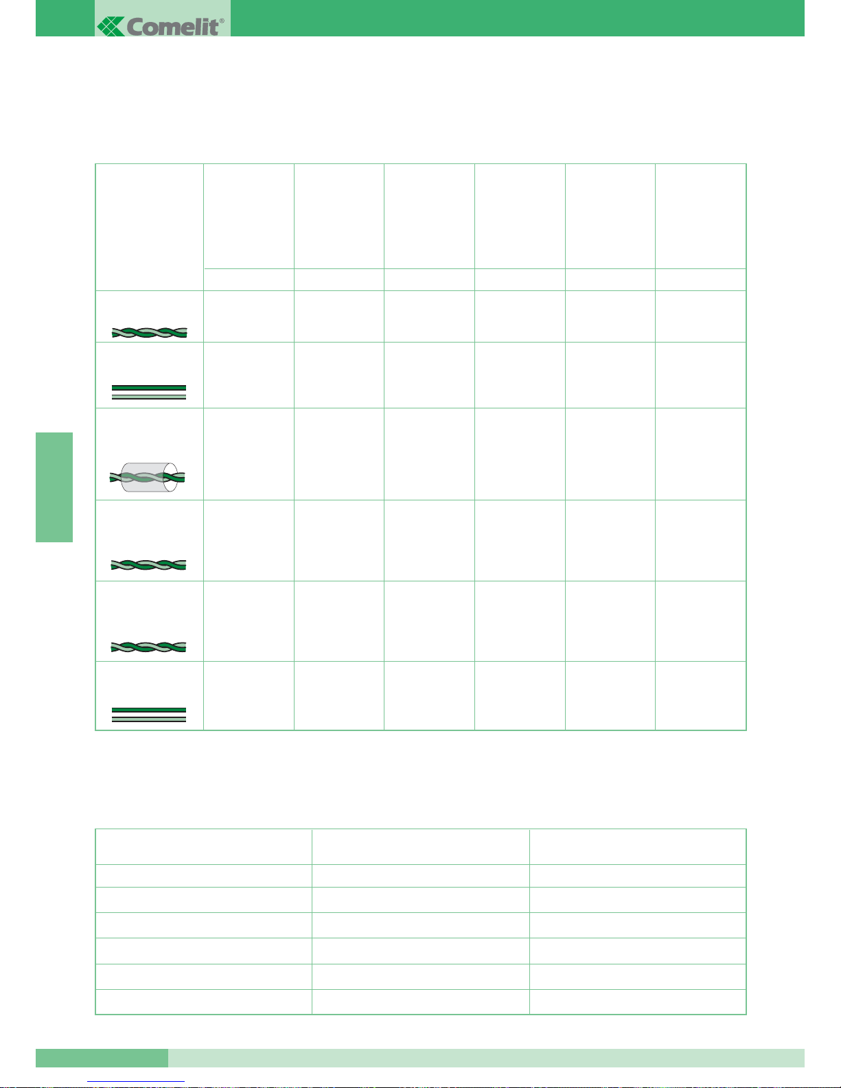
Maximale afstanden en eigenschappen van de aders
De monitoren worden aangesloten op een omkeerbare buslijn. Indien er kabels worden gebruikt die niet in de tabel worden beschreven,
kunnen wij niet garanderen over welke afstand deze kabel een goed videosignaal kan behouden. Gebruik dus alleen kabels die in de
onderstaande tabel worden omschreven.
Maximale afstanden voor de voedingsaders van een extra monitor en de buitenapparatuur
Type kabel
Getwist aderpaar
doorsn. 0.28 mm
2
(Ø 0.6 mm)*
Kabel UTP5 cat 5
AWG 24 doorsn.
0.2 mm
2
(Ø 0.5 mm)*
200 m
150 m
120 m
100 m
200 m
100 m
80 m
150 m
200 m
100 m
80 m
150 m
200 m
100 m
80 m
150 m
150 m
80 m
50 m
100 m
ABCDE
MAX. afstand
tussen
voedingsmixer
art. 4896 en
binnentoestel.
MAX. afstand
tussen
entreepaneel en
voedingsmixer
art. 4896.
MAX. afstand
tussen
entreepaneel
en art. 4833/A.
MAX. afstand
tussen art. 4833/A
en voedingsmixer
art. 4896.
MAX. afstand tussen entreepaneel
en voedingsmixer
of versterker
art. 4833/A
met art. 4834/2
60 m
40 m
30 m
40 m
80 m 150 m 150 m 150 m 100 m 40 m
H
MAX. afstand
tussen aftakblokje
art.1214/2 en
binnentoestel.
Comelit kabel art. 4577
doorsn. 1 mm
2
(Ø 1.2 mm)
Tweeaderige kabel doorsn.
1.5mm2(Ø 1.4 mm)**
Getwiste en afgeschermde kabel doorsn. 1 mm
2
(Ø 1.2 mm)*
Doorsnede van de ader
4 m
10 m
20 m
30 m
40 m
10 m
25 m
50 m
100 m
150 m
FG
MAX. afstand tussen transformator
art. 1195 en entreepaneel.
MAX. afstand tussen voeding
art. 1212/B en monitor.
0.28 mm
2
(Ø0.6 mm)
0.5 mm
2
(Ø0.8 mm)
1 mm
2
(Ø1.2 mm)
1.5 mm
2
(Ø1.4 mm)
2 mm
2
(Ø1.6 mm)
Tweeaderige kabel doorsn.
0.5 mm2(Ø0.8 mm)**
120 m 100 m 100 m 100 m 80 m 40 m
* Bij meeraderige kabel (aders per twee getwist) heeft het de voorkeur één aderpaar te gebruiken voor het systeem (buslijn). Indien het nood-
zakelijk is spanningsverlies te voorkomen, in het geval van lange afstanden, is het mogelijk een aderpaar samen te nemen voor één busader.
** Bij meeraderige kabel (aders per twee getwist) is het noodzakelijk slechts twee aders te gebruiken en wordt geadviseerd de aders niet
dubbel te nemen voor aderdoorsnede-compensatie.
GROUP S.P.A.
MT SB2 01
82
NEDERLANDS
Page 84
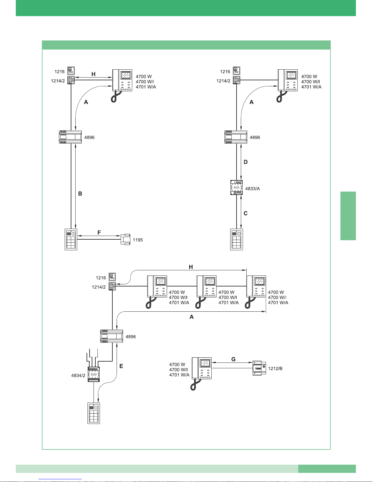
Afbeeldingen voor de afstanden
MT SB2 01
83
MT SB2 01
NEDERLANDS
Page 85
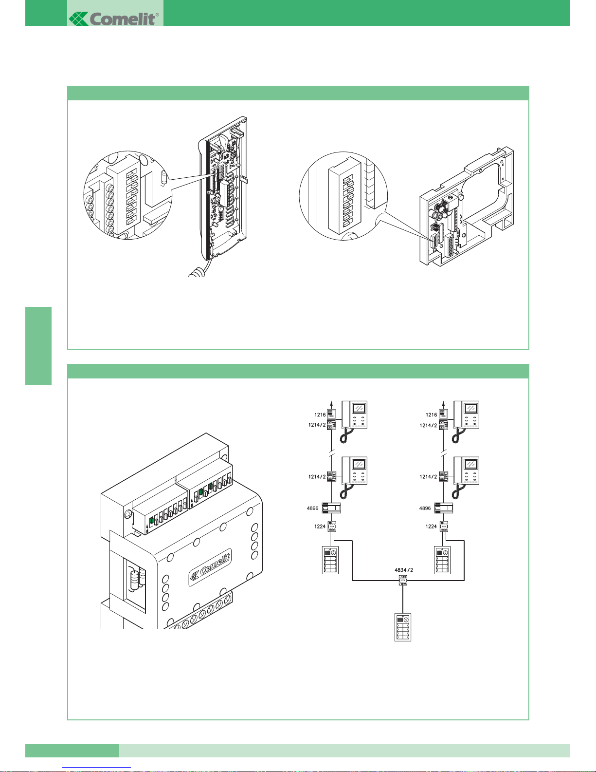
CONFIGURATIE VAN DE APPARATUUR
Programmering deurtelefoon art. 2408W/A, 2410W, 2428W en grondplaat art. 4714W/2
• Iedere deurtelefoon of grondplaat van het systeem wordt
ingesteld met een eigen code; deze code moet ingesteld
worden door middel van de dipswitches in de deurtelefoon of op
de grondplaat van de monitor (zie afbeeldingen).
• De gebruikerscode moet ingesteld worden volgens de tabel
op pag. 85.
• Deze codering kan altijd worden ingesteld, ook zónder
spanning op het systeem.
1 2
3
4 5
6 7
8
1 2
3
4 5
6 7
8
Programmering schakelapparaat art. 1224
• Elke selector is uitgevoerd met 2 dipswitches met ieder 8
schakelaars (zie afbeelding). Met de twee dipswitches kan de
minimale MIN en de maximale MAX range van codes worden
ingesteld op de selector.
•
Let op: de MIN en de MAX dipswitches vertegenwoordigen de laagste
en hoogste code die op deze buslijn kan worden aangesloten.
• Om de waarden in te stellen verwijzen wij naar pag. 85.
• Bij meerdere selektors mogen de codes elkaar niet overlappen.
PORTA PRINCIPALE DAL N° 1÷20.
SCALA A SCALA B
4700 W
4700 W/I
4701 W/A
4700 W
4700 W/I
4701 W/A
N° 1÷10 N° 11÷20
4700 W
4700 W/I
4701 W/A
4700 W
4700 W/I
4701 W/A
MAX
MIN
1
2
3
4
5
6
7
8
1
2
3
4
5
6
7
8
O
N
O
N
• Voorbeeld van het instellen van een deurselektor art. 1224
van portiek A, minimaal nummer 1, maximaal nummer 10.
GROUP S.P.A.
MT SB2 01
84
NEDERLANDS
PORTIEK A
NR. 1÷10.
HOOFDINGANG VAN NR. 1÷20.
PORTIEK B
N° 11÷20.
Page 86
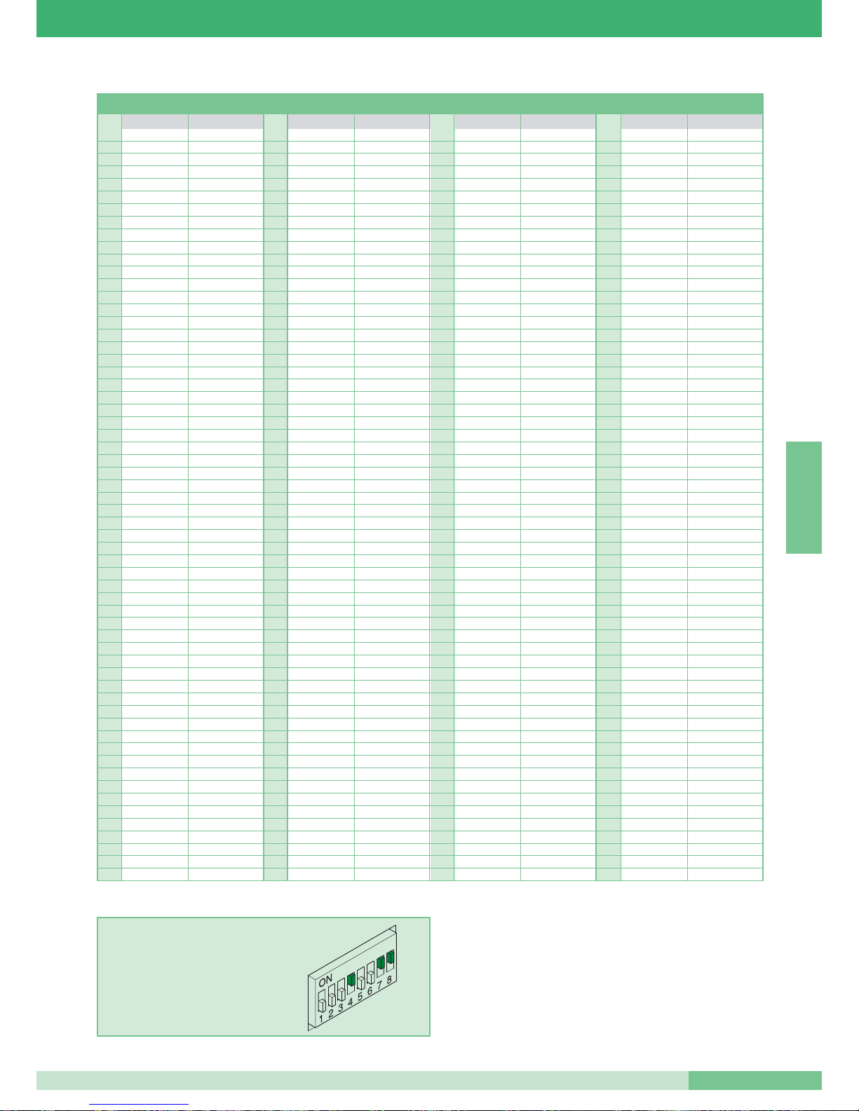
Programmeringtabel van de dipswitches
11 61 1,3,4,5,6 121 1,4,5,6,7 181 1,3,5,6,8
22 62 2,3,4,5,6 122 2,4,5,6,7 182 2,3,5,6,8
3 1,2 63 1,2,3,4,5,6 123 1,2,4,5,6,7 183 1,2,3,5,6,8
43 64 7 124 3,4,5,6,7 184 4,5,6,8
5 1,3 65 1,7 125 1,3,4,5,6,7 185 1,4,5,6,8
6 2,3 66 2,7 126 2,3,4,5,6,7 186 2,4,5,6,8
71,2,3 67 1,2,7 127 1,2,3,4,5,6,7 187 1,2,4,5,6,8
84 68 3,7 128 8 188 3,4,5,6,8
9 1,4 69 1,3,7 129 1,8 189 1,3,4,5,6,8
10 2,4 70 2,3,7 130 2,8 190 2,3,4,5,6,8
11 1,2,4 71 1,2,3,7 131 1,2,8 191 1,2,3,4,5,6,8
12 3,4 72 4,7 132 3,8 192 7,8
13 1,3,4 73 1,4,7 133 1,3,8 193 1,7,8
14 2,3,4 74 2,4,7 134 2,3,8 194 2,7,8
15 1,2,3,4 75 1,2,4,7 135 1,2,3,8 195 1,2,7,8
16 5 76 3,4,7 136 4,8 196 3,7,8
17 1,5 77 1,3,4,7 137 1,4,8 197 1,3,7,8
18 2,5 78 2,3,4,7 138 2,4,8 198 2,3,7,8
19 1,2,5 79 1,2,3,4,7 139 1,2,4,8 199 1,2,3,7,8
20 3,5 80 5,7 140 3,4,8 200 4,7,8
21 1,3,5 81 1,5,7 141 1,3,4,8 201 1,4,7,8
22 2,3,5 82 2,5,7 142 2,3,4,8 202 2,4,7,8
23 1,2,3,5 83 1,2,5,7 143 1,2,3,4,8 203 1,2,4,7,8
24 4,5 84 3,5,7 144 5,8 204 3,4,7,8
25 1,4,5 85 1,3,5,7 145 1,5,8 205 1,3,4,7,8
26 2,4,5 86 2,3,5,7 146 2,5,8 206 2,3,4,7,8
27 1,2,4,5 87 1,2,3,5,7 147 1,2,5,8 207 1,2,3,4,7,8
28 3,4,5 88 4,5,7 148 3,5,8 208 5,7,8
29 1,3,4,5 89 1,4,5,7 149 1,3,5,8 209 1,5,7,8
30 2,3,4,5 90 2,4,5,7 150 2,3,5,8 210 2,5,7,8
31 1,2,3,4,5 91 1,2,4,5,7 151 1,2,3,5,8 211 1,2,5,7,8
32 6 92 3,4,5,7 152 4,5,8 212 3,5,7,8
33 1,6 93 1,3,4,5,7 153 1,4,5,8 213 1,3,5,7,8
34 2,6 94 2,3,4,5,7 154 2,4,5,8 214 2,3,5,7,8
35 1,2,6 95 1,2,3,4,5,7 155 1,2,4,5,8 215 1,2,3,5,7,8
36 3,6 96 6,7 156 3,4,5,8 216 4,5,7,8
37 1,3,6 97 1,6,7 157 1,3,4,5,8 217 1,4,5,7,8
38 2,3,6 98 2,6,7 158 2,3,4,5,8 218 2,4,5,7,8
39 1,2,3,6 99 1,2,6,7 159 1,2,3,4,5,8 219 1,2,4,5,7,8
40 4,6 100 3,6,7 160 6,8 220 3,4,5,7,8
41 1,4,6 101 1,3,6,7 161 1,6,8 221 1,3,4,5,7,8
42 2,4,6 102 2,3,6,7 162 2,6,8 222 2,3,4,5,7,8
43 1,2,4,6 103 1,2,3,6,7 163 1,2,6,8 223 1,2,3,4,5,7,8
44 3,4,6 104 4,6,7 164 3,6,8 224 6,7,8
45 1,3,4,6 105 1,4,6,7 165 1,3,6,8 225 1,6,7,8
46 2,3,4,6 106 2,4,6,7 166 2,3,6,8 226 2,6,7,8
47 1,2,3,4,6 107 1,2,4,6,7 167 1,2,3,6,8 227 1,2,6,7,8
48 5,6 108 3,4,6,7 168 4,6,8 228 3,6,7,8
49 1,5,6 109 1,3,4,6,7 169 1,4,6,8 229 1,3,6,7,8
50 2,5,6 110 2,3,4,6,7 170 2,4,6,8 230 2,3,6,7,8
51 1,2,5,6 111 1,2,3,4,6,7 171 1,2,4,6,8 231 1,2,3,6,7,8
52 3,5,6 112 5,6,7 172 3,4,6,8 232 4,6,7,8
53 1,3,5,6 113 1,5,6,7 173 1,3,4,6,8 233 1,4,6,7,8
54 2,3,5,6 114 2,5,6,7 174 2,3,4,6,8 234 2,4,6,7,8
55 1,2,3,5,6 115 1,2,5,6,7 175 1,2,3,4,6,8 235 1,2,4,6,7,8
56 4,5,6 116 3,5,6,7 176 5,6,8 236 3,4,6,7,8
57 1,4,5,6 117 1,3,5,6,7 177 1,5,6,8 237 1,3,4,6,7,8
58 2,4,5,6 118 2,3,5,6,7 178 2,5,6,8 238 2,3,4,6,7,8
59 1,2,4,5,6 119 1,2,3,5,6,7 179 1,2,5,6,8 239 1,2,3,4,6,7,8
60 3,4,5,6 120 4,5,6,7 180 3,5,6,8
*240 5,6,7,8
*N.B.: de code 240 is gereserveerd voor de portierscentrale
VOORBEELD instelling code 200.
Gebruik.
dipswitches op ON Naam gebruiker
Gebruik.
dipswitches op ON Naam gebruiker
Gebruik.
dipswitches op ON Naam gebruiker
Gebruik.
dipswitches op ON Naam gebruiker
MT SB2 01
85
MT SB2 01
NEDERLANDS
Page 87
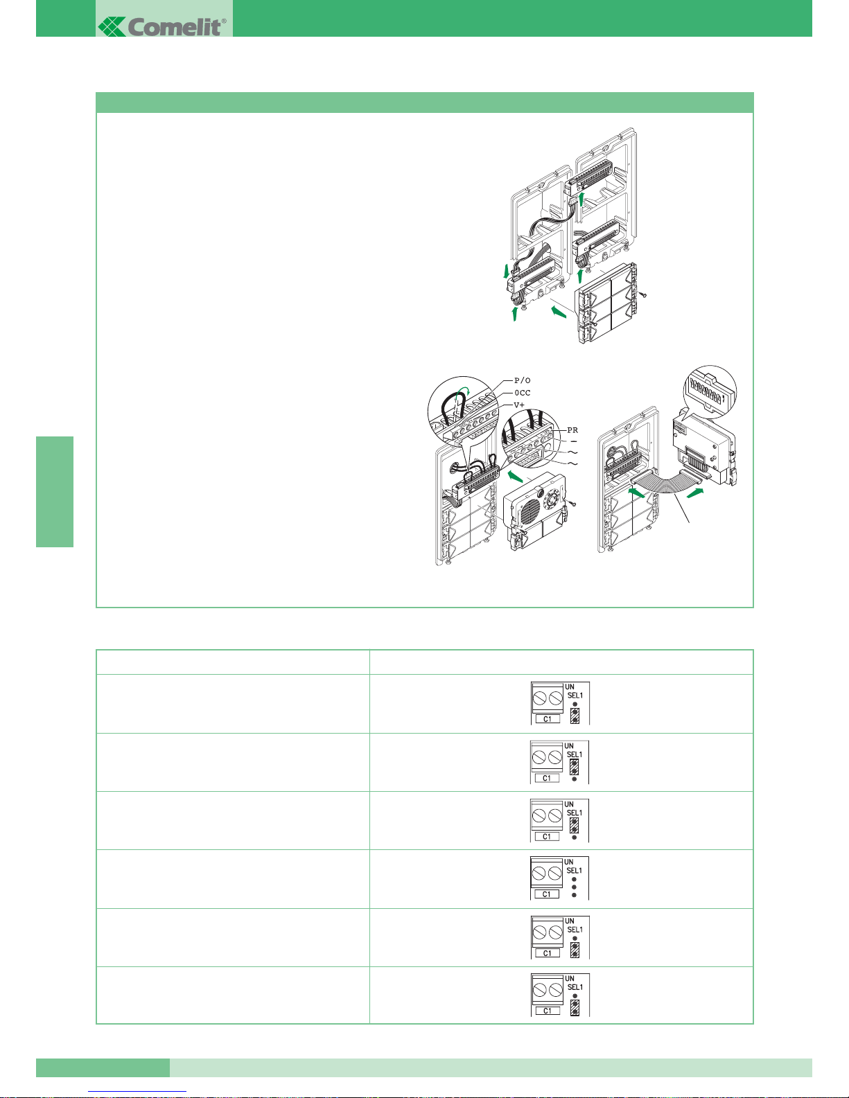
Programmering beldrukkers met audio art. 1602 en video art.4660 en modulen art. 3323/4 en 3323/6
1. Verbind de drukknopmodulen 3323/4 en 3323/6 met de
modulen 4660 of 1602 d.m.v. de meegeleverde verbindingen.
Steek de modulen 3323/4 en 3323/6 in de bijbehorende
aansluitblokken (zie figuur 1).
2. Sluit de voeding aan op de klemmen ~ ~ van de module 4660
of 1602 en maak daarna een draadbrug tussen de klemmen
PR en – en verzet de doorverbinding (vanaf P/O) van OCC
naar V+ (zie figuur 2). Verbind het aansluitblok met de modulen
4660 of 1602 zoals afgebeeld. Attentie: de modulen 3323/4 en
3323/6 dienen al gemonteerd te zijn, voordat met de
programmering wordt gestart (zie figuur 2).
OPMERKING: er is een speciale programmeerkabel
art. 3309 leverbaar als accessoire voor het verbinden van het
aansluitblok en de module 4660 of 1602 tijdens het
programmeren (zie figuur 3).
3. Zet de dipswitch aan de achterzijde van de luidsprekermoduul
op dezelfde code als die op de corresponderende huistelefoon
of monitor ingesteld is volgens de tabel op pag. 85.
4. Druk nu op de drukknop die op deze code moet worden
geprogrammeerd. Als de programmering wordt opgeslagen,
wordt dit bevestigd door een bevestigingstoon.
5. Zet na de programmering de doorverbindingen weer in de
oorspronkelijke posities,
PR op PR en P/O op OCC.
Instellen als hoofdpaneel of secundaire ingang.
De modulen 4660 of 1602 functioneren normaal als
hoofdentree (bezet signaal gedurende een ingestelde tijd). Om
deze in te stellen als secondair entreepaneel (bezet signaal als
de buslijn in gebruik is) dienen alle dipswitches op “ON”
ingesteld te worden.
fig. 1
fig. 3
art. 3309
fig. 2
1
2
3
4
5
6
7
8
O
N
GROUP S.P.A.
MT SB2 01
86
Tabel met de instellingen van art. 1216 behorend bij de gebruikte bekabeling
Type kabel Instelling art. 1216
Comelit kabel art. 4577 doorsn. 1 mm
2
(Ø 1.2 mm)
2
2
1
1
Tweeaderige kabel doorsn. 1.5 mm
2
(Ø 1.4 mm)
Getwiste en afgeschermde kabel doorsn. 1 mm
2
(Ø 1.2 mm)
Getwist aderpaar doorsn. 0.28 mm
2
(Ø 0.6 mm)
Kabel UTP5 cat 5 AWG 24 doorsn. 0.2 mm
2
(Ø 0.5 mm)
Tweeaderige kabel doorsn. 0.5 mm
2
(Ø 0.8 mm)
2
NEDERLANDS
Page 88
WERKING
• De bezoeker drukt op de beldrukker en activeert daarmee de
beltoon van de binnentoestellen.
• Het entreepaneel laat het belgeluid horen waarmee bevestigd
wordt dat er gebeld is; als u, in een installatie met meerdere
ingangen, het bevestigingsgeluid niet hoort, dan betekent dit dat
het systeem in communicatie is met een ander entreepaneel dat in
dezelfde gebruikersgroep geïnstalleerd is. Als de bezetmodule art.
3346 geïnstalleerd is, wacht dan totdat de LED’s in de module
uitgaan alvorens opnieuw te bellen.
Als het art. 3340 geïnstalleerd is, dan wordt er op het display
aangegeven dat de installatie in gesprek is.
• Als de hoorn wordt opgenomen kan er een gesprek plaatsvinden
met het entreepaneel.
• De toets aangeduid met het symbool van de sleutel activeert
gedurende ongeveer
2 seconden het elektrische slot buiten.
• Wanneer in een video-intercom systeem wordt aangebeld, gaan
de infrarood LED’s bij de camera aan (onzichtbaar voor het
menselijk oog) om de bezoeker te verlichten; het beeld blijft
gedurende ongeveer 90 seconden lang op de monitor
• Voor de afstelling van het volume van de microfoon en het volume
van de beltoon van de deurtelefoons zie pag. 72 en 73.
• Voor de afstelling van het volume van de bel van de monitoren zie
pag. 68 en 69.
• Voor de afstelling van het audio volume buiten zie pag. 10.
• Voor het activeren van de
beeldoproep dient knop 2 langer dan 2
seconden
ingedrukt gehouden worden (zie variant H pag. 111).
Als deze instelling is gemaakt, wordt dit bevestigd door een toon
in de hoorn.
• De
beeldoproep vindt plaats (als de functie geactiveerd is) door
knop 2 in te drukken. Als er twee entreepanelen met camera
geïnstalleerd zijn, kunt u, door knop 2 voor de beeldoproep van de
monitor nogmaals in te drukken, eerst het beeld van de ene
ingang en dan van de andere ingang verkrijgen (afwisselingfunctie
tussen de twee ingangen).
• De helderheid van de monitor kan worden veranderd door het
stelwieltje aan de onderkant te gebruiken.
• Het volume van de bel kan worden ingesteld door de schakelaar
aan de onderkant van de monitor te gebruiken.
• Met de optionele kaart art. 4703 kan de
Privacy functie ingesteld
worden. Door de knop 4 van de monitor langer dan 2 seconden
ingedrukt te houden gaat de LED branden die aangeeft dat de
monitor in de Privacy modus is ingesteld (zie variant I pag 112).
In de privacy modus belt de monitor niet, maar er komt wel beeld;
u heeft toch de mogelijkheid met buiten te praten nadat
er gebeld is.
• Wanneer de hoorn er binnen opgelegd wordt, heeft u nog enkele
seconden de tijd om het gesprek met buiten te hervatten.
Vanaf het moment dat de hoorn er opgelegd is verlopen er nog
enkele seconden voordat het beeld van de monitor verdwijnt.
• De als
primair ingestelde monitor (fabrieksinstelling van de
grondplaat art. 4714W/2) gaat aan als er gebeld wordt en bij
beeldoproep, ook als dit een extra monitor is met dezelfde
gebruikerscode en een eigen voeding.
• De als
secundair ingestelde monitor (zie variant SB2/A1-A2)
geeft geen beeld als er gebeld wordt, maar kan aangezet worden
door de knop 2 in te drukken (passieve beeldoproep). Bij deze
monitor is actieve beeldoproep niet mogelijk (oproep zonder dat er
is aangebeld).
• Monitoren en deurtelefoons met dezelfde gebruikerscode bellen
allemaal tegelijk (onafhankelijk van het feit of ze primair of
secundair zijn) als er vanaf buiten wordt gebeld, maar ook als er
een etagebel is aangesloten.
MT SB2 01
87
MT SB2 01
NEDERLANDS
Page 89
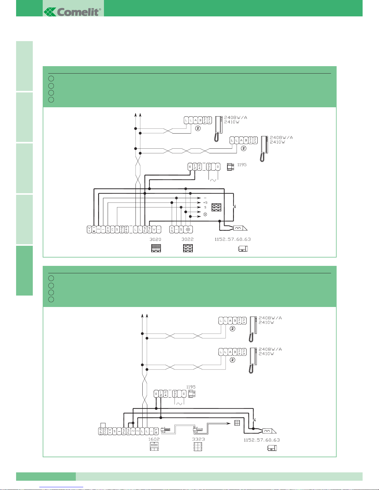
SCHEMI DI COLLEGAMENTO
WIRING DIAGRAMS
SCHEMAS DE CONNEXION
AANSLUITSCHEMA’S
Impianto 1 porta audio Serie Logicom.
System with 1 Logicom Series audio entrance.
Installation avec 1 porte audio Série Logicom.
Installatie 1 audio entreepaneel Serie Logicom.
SBC/01L
I
GB
F
NL
Impianto 1 porta audio Serie Powercom.
System with 1 Powercom Series audio entrance.
Installation avec 1 porte audio Série Powercom.
Installatie 1 audio entreepaneel Serie Powercom.
SBC/01
I
GB
F
NL
GROUP S.P.A.
MT SB2 01
88
ITALIANOENGLISHFRANÇAISNEDERLANDSA
Page 90
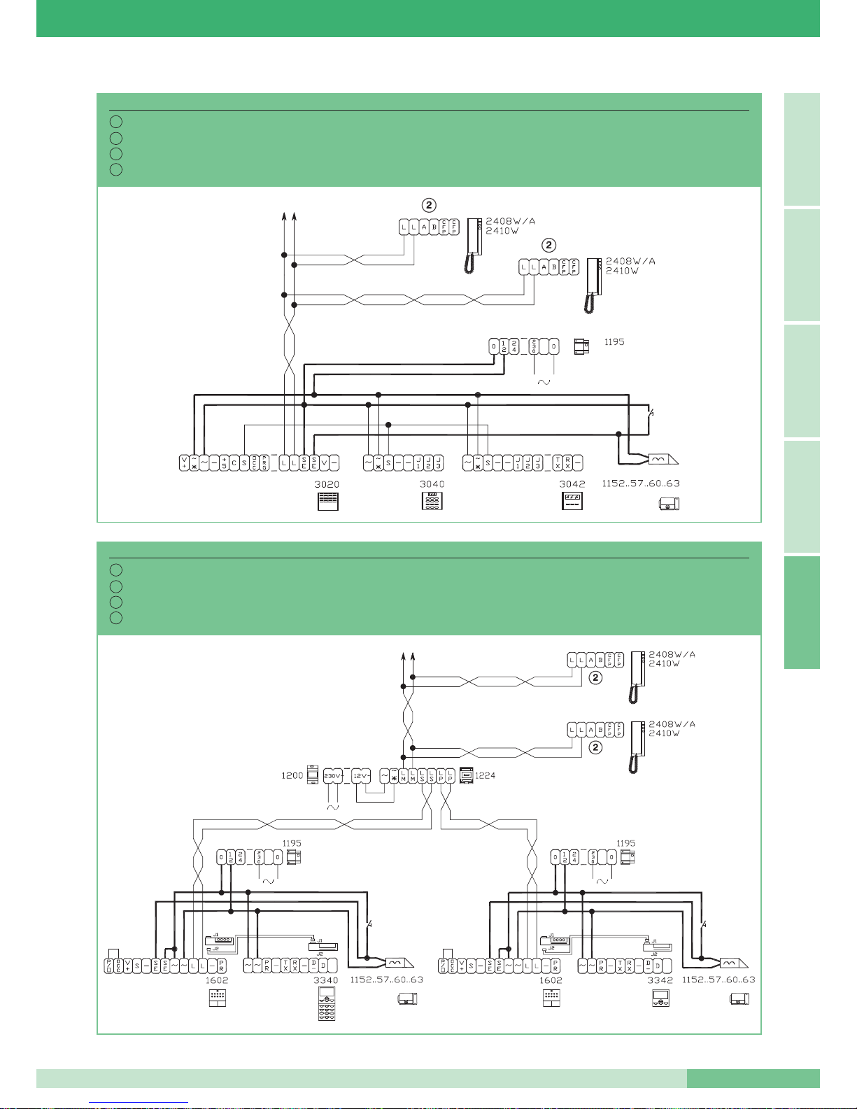
Impianto 1 porta audio digitale Serie Logicom 3040 (3070) – 3042 (3072).
System with 1 Logicom Series digital audio entrance 3040 (3070) – 3042 (3072).
Installation avec 1 porte audio numérique Série Logicom 3040 (3070) – 3042 (3072).
Installatie 1 digitale audio entreepaneel Serie Logicom 3040 (3070) – 3042 (3072)
SBC/02L
I
GB
F
NL
Impianto 2 porte audio digitali Serie Powercom 3340 - 3342.
System with 2 Powercom Series digital audio entrances 3340 - 3342.
Installation avec 2 portes audio numériques Série Powercom 3340 - 3342.
Installatie 2 digitale audio entreepanelen Serie Powercom 3340 - 3342.
SBC/02
I
GB
F
NL
MT SB2 01
89
MT SB2 01
ITALIANOENGLISH
FRANÇAIS
NEDERLANDSA
Page 91
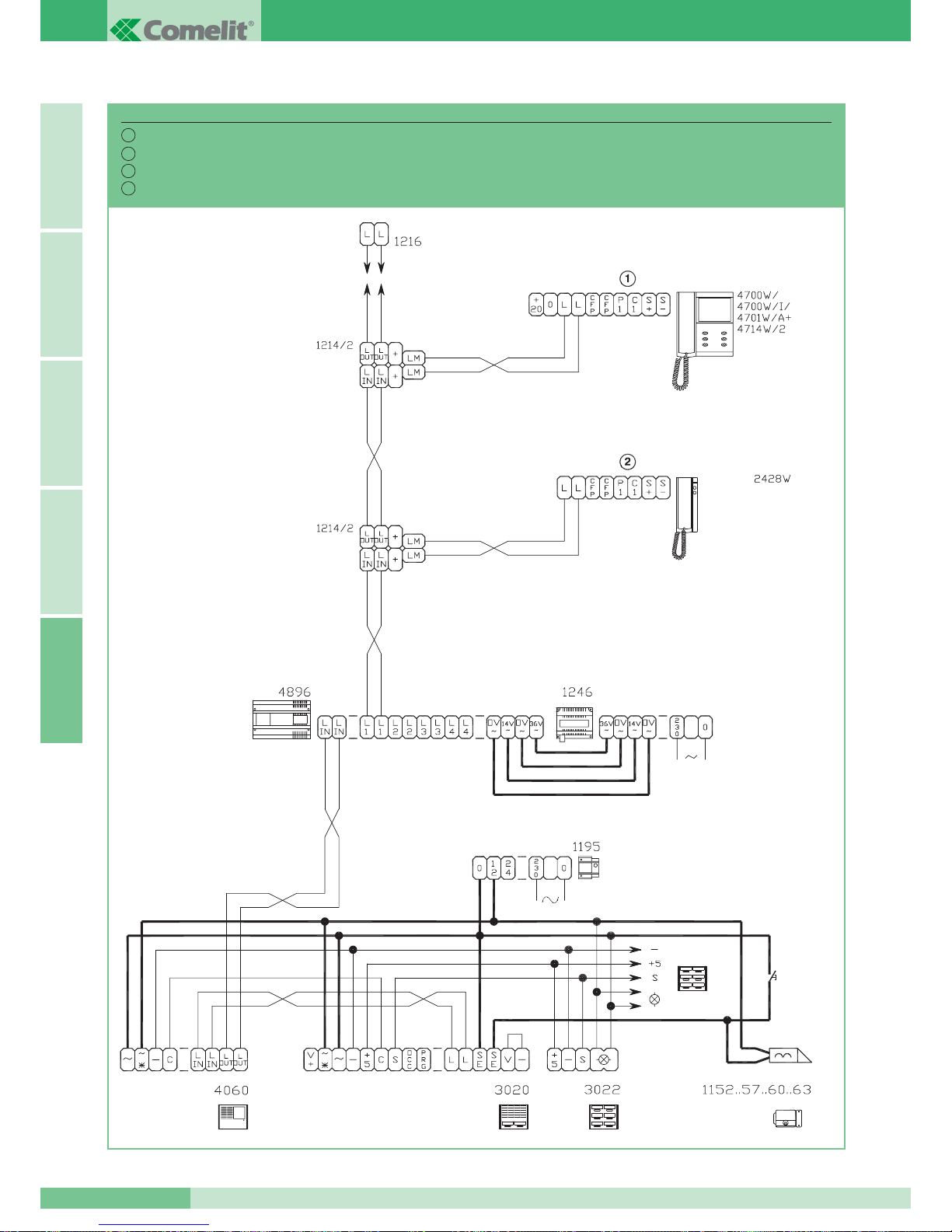
Impianto 1 porta video Serie Logicom.
System with 1 Logicom Series video entrance.
Installation avec 1 porte vidéo Série Logicom.
Installatie 1 video entreepaneel Serie Logicom.
SB2V/01L
I
GB
F
NL
GROUP S.P.A.
MT SB2 01
90
ITALIANOENGLISHFRANÇAISNEDERLANDSA
Page 92
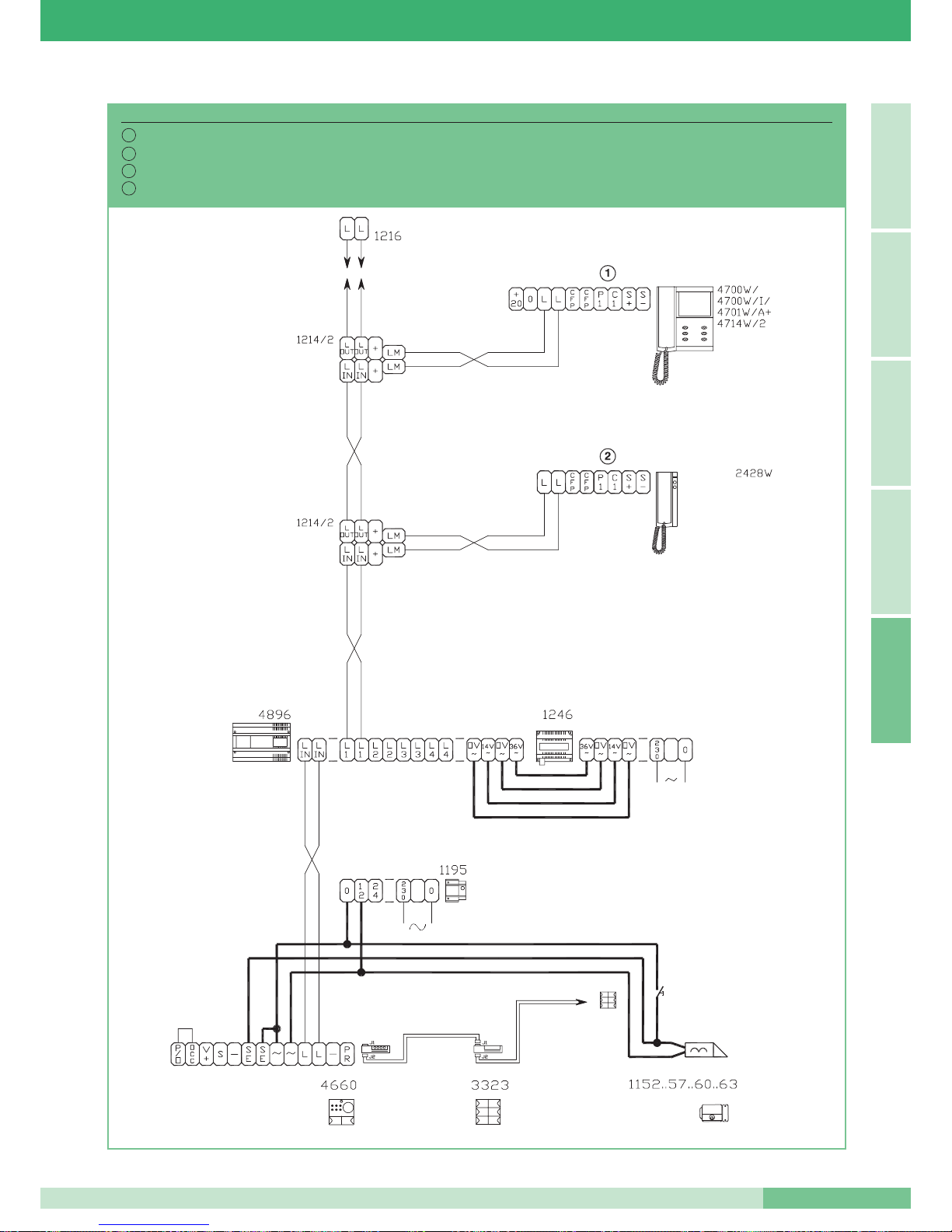
Impianto 1 porta video Serie Powercom.
System with 1 Powercom Series video entrance.
Installation avec 1 porte vidéo Série Powercom.
Installatie 1 video entreepaneel Serie Powercom.
SB2V/01
I
GB
F
NL
MT SB2 01
91
MT SB2 01
ITALIANOENGLISH
FRANÇAIS
NEDERLANDSA
Page 93
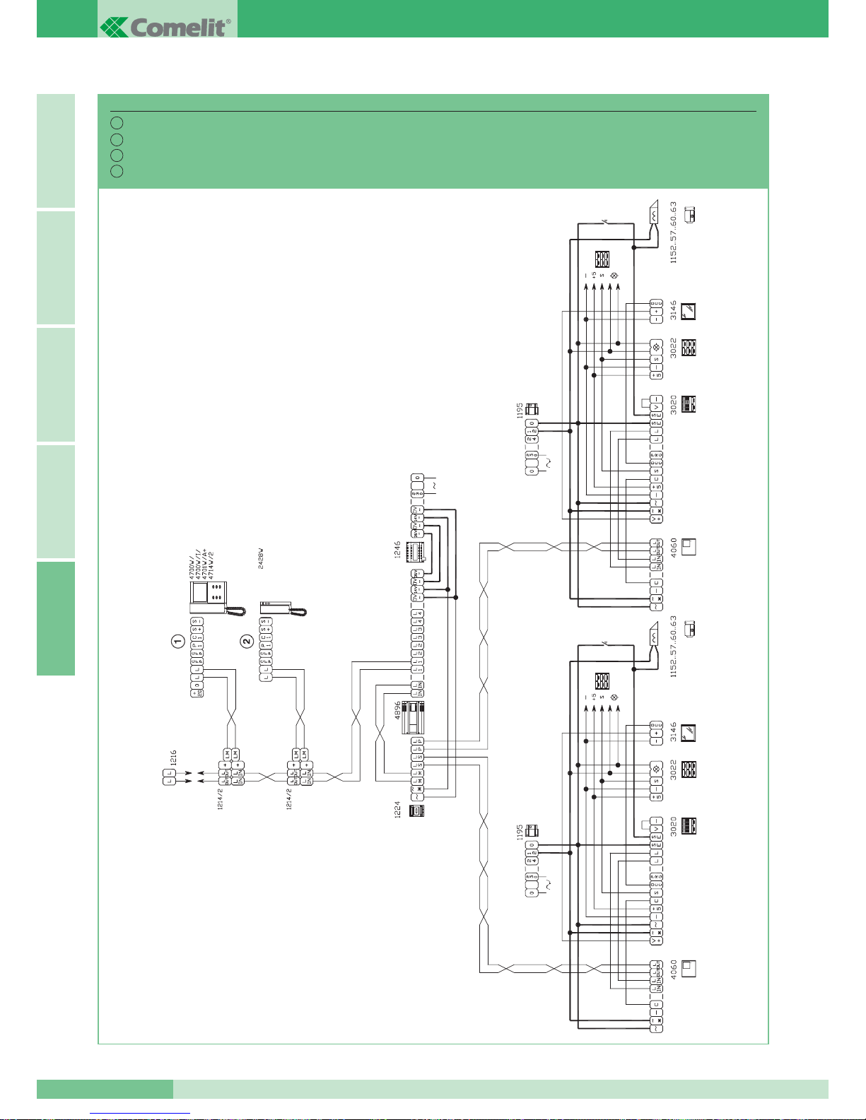
GROUP S.P.A.
MT SB2 01
92
ITALIANOENGLISHFRANÇAISNEDERLANDSA
Impianto 2 porte video Serie Logicom.
System with 2 Logicom Series video entrances.
Installation avec 2 portes vidéo Série Logicom.
Installatie 2 video entreepanelen Serie Logicom.
SB2V/03L
I
GB
F
NL
Page 94
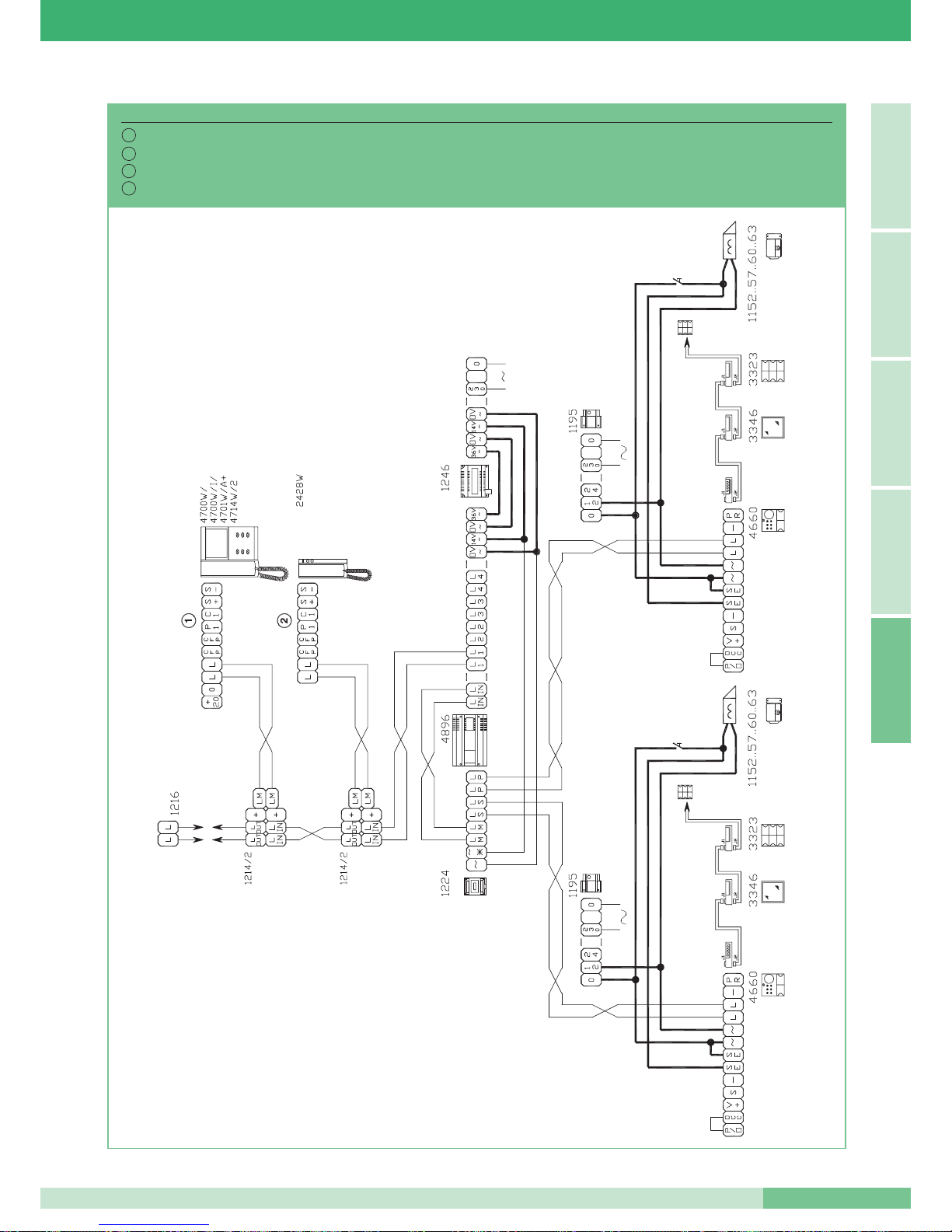
MT SB2 01
93
MT SB2 01
ITALIANOENGLISH
FRANÇAIS
NEDERLANDSA
Impianto 2 porte video Serie Powercom.
System with 2 Powercom Series video entrances.
Installation avec 2 portes vidéo Série Powercom.
Installatie 2 video entreepanelen Serie Powercom.
SB2V/03
I
GB
F
NL
Page 95
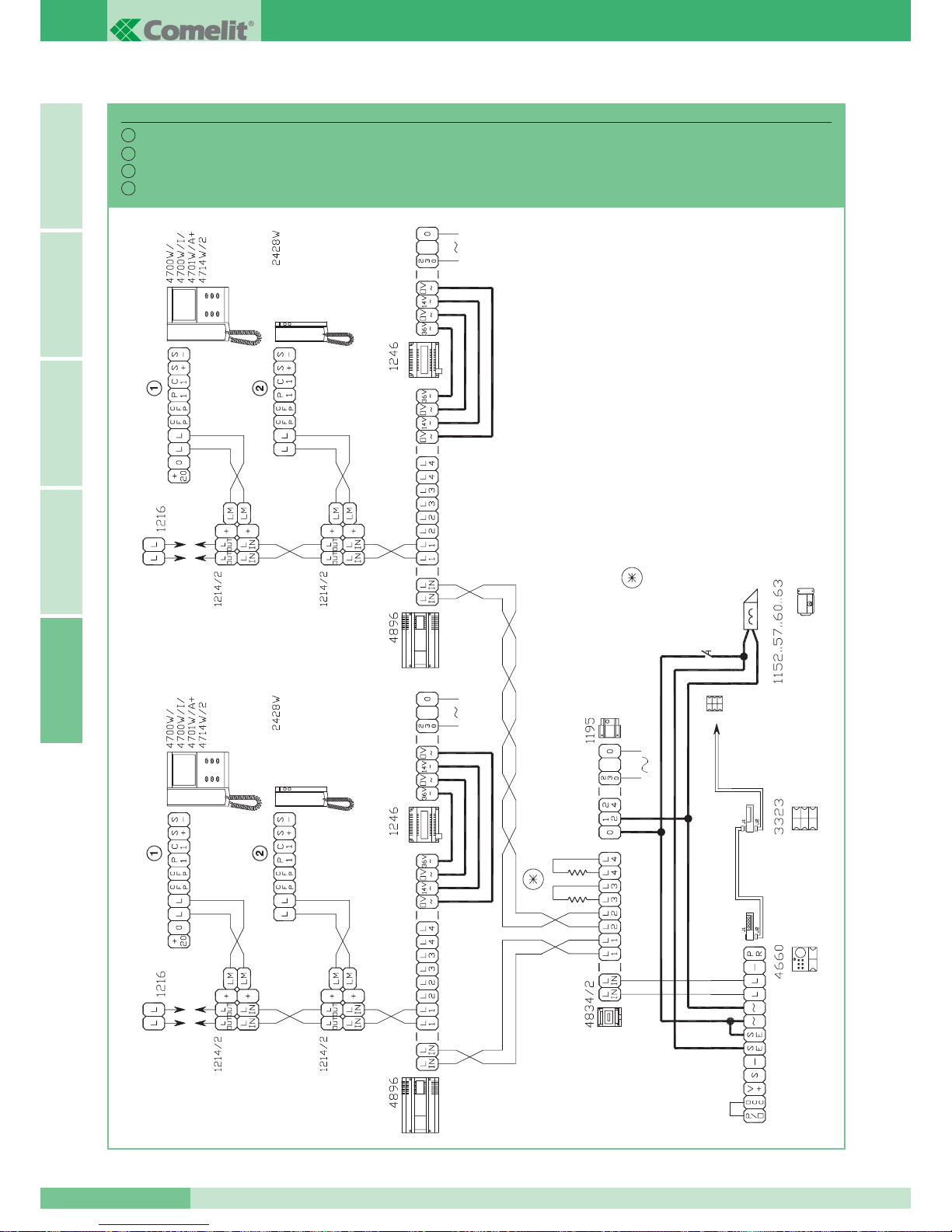
TAGLIARE SOLO LA RESISTENZA DELL’USCITA UTILIZZATA.
ONLY CUT THE RESISTANCE OF THE OUTPUT USED.
COUPER SEULEMENT LA RESISTANCE DE LA SORTIE UTILISEE
VERWIJDER ALLEEN DE WEERSTAND ALS DE UITGANG
GEBRUIKT WORDT.
GROUP S.P.A.
MT SB2 01
94
ITALIANOENGLISHFRANÇAISNEDERLANDSA
Impianto con 1 porta video Serie Powercom e max 4 Miscelatori-alimentatori Art. 4896.
System with 1 Powercom Series video entrance and MAX 4 Mixers-power supplies Art. 4896.
Installation avec 1 porte vidéo Série Powercom et MAX 4 mélangeurs-alimentations Art. 4896.
Installatie met 1 video entreepaneel Serie Powercom en MAX. 4 voedingmixers art. 4896.
SB2V/012
I
GB
F
NL
Page 96
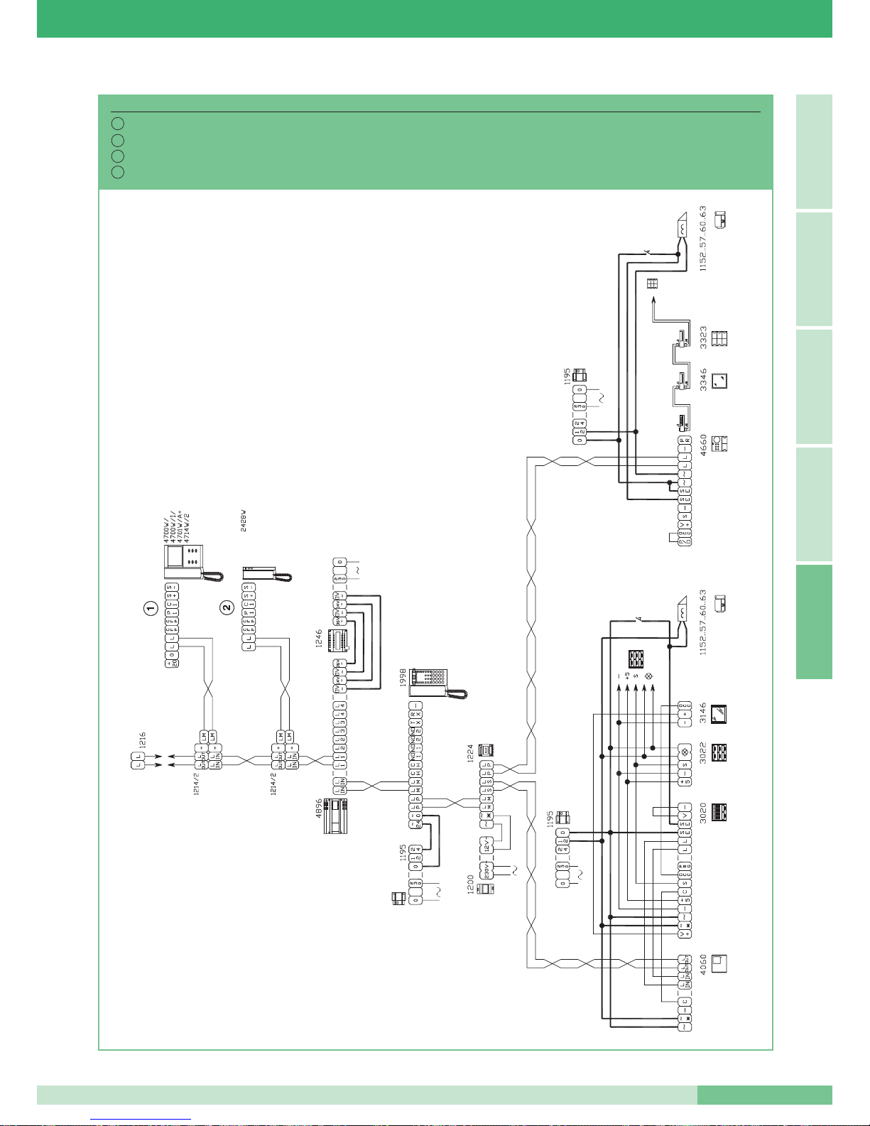
MT SB2 01
95
MT SB2 01
ITALIANOENGLISH
FRANÇAIS
NEDERLANDSA
Impianto con 2 porte video e centralino di portineria Art. 1998.
System with 2 video entrances and porter switchboard Art. 1998.
Installation avec 2 portes vidéo et un HP-micro Art. 1998.
Installatie met 2 video entreepanelen en portierscentrale art. 1998.
SB2V/013
I
GB
F
NL
Page 97
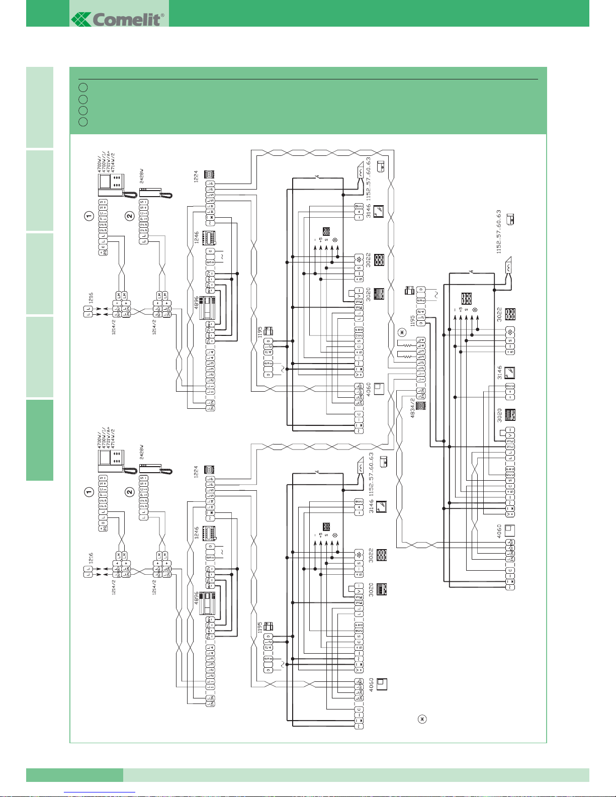
TAGLIARE SOLO LA RESISTENZA
DELL’USCITA UTILIZZATA.
ONLY CUT THE RESISTANCE OF THE
OUTPUT USED.
COUPER SEULEMENT LA RESISTANCE
DE LA SORTIE UTILISEE
VERWIJDER ALLEEN DE WEERSTAND
ALS DE UITGANG GEBRUIKT WORDT.
GROUP S.P.A.
MT SB2 01
96
ITALIANOENGLISHFRANÇAISNEDERLANDSA
Impianto 1 ingresso principale video max 4 secondari video serie Logicom.
System with 1 main video entrance and MAX 4 Logicom series secondary videos.
Installation avec 1 entrée principale vidéo MAX 4 secondaires vidéo série Logicom.
Installatie 1 video hoofdentreepaneel met MAX. 4 secundaire video entreepanelen serie Logicom.
SB2V/EN/112L
I
GB
F
NL
Page 98
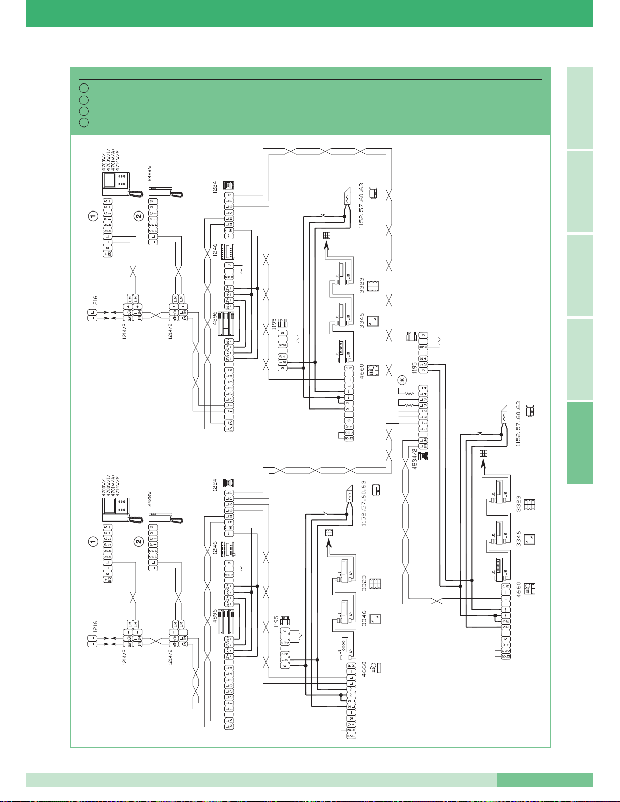
MT SB2 01
97
MT SB2 01
ITALIANOENGLISH
FRANÇAIS
NEDERLANDSA
Impianto 1 ingresso principale video max 4 secondari video serie Powercom.
System with 1 main video entrance and MAX 4 Powercom series secondary videos.
Installation avec 1 entrée principale vidéo MAX 4 secondaires vidéo série Powercom.
Installatie 1 video hoofd-entreepaneel met MAX. 4 secundaire video entreepanelen serie Powercom.
SB2V/EN/112
I
GB
F
NL
Page 99
IVARIANTI AGLI SCHEMI BASE
DI COLLEGAMENTO
Collegamento di più utenti con lo stesso codice utente (MAX 3).
E’ possibile avere non più di 3 posti interni con lo stesso codice utente.
I monitor con lo stesso codice utente devono stare sulla stessa
diramazione di montante cioè sulla stessa uscita L1L1 o L2L2 o L3L3 o
L4L4 del Miscelatore-alimentatore Art. 4896.
Agendo su JP1 della staffa Art. 4714W/2 i posti interni video possono
essere impostati come
Principali (si accende su chiamata e su
autoaccensione) o come Secondari (non si accende su chiamata ma su
richiesta video premendo il pulsante 2).
A seconda della tipologia di impianto bisogna impostare le staffe dei
monitor supplementari come di seguito descritto.
GB VARIANTS TO THE BASIC
WIRING DIAGRAMS
Connection of several users with the same user code (MAX 3).
It is possible to have no more than 3 internal units with the same user
code. The monitors with the same user code must be on the same riser
branch, i.e. on the same L1L1 or L2L2 or L3L3 or L4L4 output of the
Mixer-power supply Art. 4896.
Working on JP1 of bracket Art. 4714W/2, the internal video units can be
set as
Main (they light up on a call and on Self-ignition) or as Secondary
(they do not light up on a call but on video request by pressing push-button
2). According to the type of system, the additional monitor brackets must
be set as described below.
FVARIANTES AUX SCHEMAS
DE CONNEXION DE BASE
Connexion de plusieurs usagers ayant le même code usager (MAX 3).
Possibilité d’avoir au maximum 3 postes intérieurs avec le même code
usager. Les moniteurs ayant le même code usager doivent se trouver sur
la même dérivation du montant, c’est-à-dire sur la même sortie L1L1 ou
L2L2 ou L3L3 ou L4L4 du mélangeur-alimentation Art. 4896.
En intervenant sur JP1 de la bride Art. 4714W/2, les postes intérieurs
vidéo peuvent être programmés comme
Principaux (ils se branchent à
l’appel et au autoallumage) ou comme Secondaires (ils ne se branchent
pas à l’appel mais à la demande vidéo en appuyant sur le bouton 2).
Selon le type d’installation, les brides des moniteurs additionnels doivent
être programmées de la manière décrite ci-dessous.
NL VARIANTEN VAN DE STANDAARD
AANSLUITSCHEMA’S
Aansluiting van meerdere gebruikers met dezelfde gebruikerscode
(MAX. 3).
Er kunnen maximaal 3 binnentoestellen met dezelfde gebruikerscode zijn.
De monitoren met dezelfde gebruikerscode dienen op dezelfde stamleiding
aangesloten te zijn d.w.z. op dezelfde uitgang L1L1 of L2L2 of L3L3 of
L4L4 van de mixervoeding art. 4896.
Met behulp van JP1 op de grondplaat art. 4714W/2 kunnen de monitoren
ingesteld worden als
Primair (gaat aan als er gebeld wordt en bij
beeldoproep) of als Secundair (gaat niet aan als er gebeld wordt, maar
het beeld kan opgeroepen worden door knop 2 in te drukken).
Naar gelang het type installatie dienen de grondplaten van de extra
monitoren ingesteld te worden zoals als volgt beschreven wordt.
GROUP S.P.A.
MT SB2 01
98
ITALIANOENGLISHFRANÇAISNEDERLANDSA
Page 100
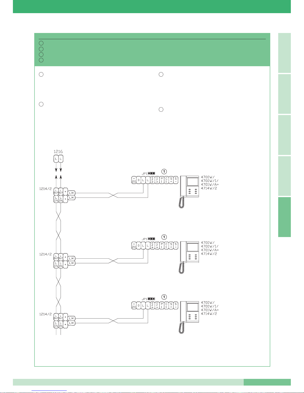
• Accensione del solo monitor Principale su chiamata.
• Accensione su pressione del pulsante2 dei monitor
Secondari dopo chiamata (Richiesta Video).
• Suoneria su tutti i monitor.
• Possibilità di eseguire
Autoaccensione sul monitor Principale.
• Ignition up only of Main monitor on a call.
• Lighting up on push-button 2 of the Secondary monitors being
pressed after a call
(Video request).
• Call tone on all the monitors.
• Possibility of carrying out Self-ignition on the Main monitor.
• Branchement seulement du moniteur
Principal sur appel.
• Branchement à l’appui sur le bouton 2 des moniteurs
Secondaires
après l’appel (Demande Vidéo).
• Sonnerie sur tous les moniteurs.
• Possibilité d’effectuer un
Autoallumage sur le
moniteur Principal.
• Alleen de hoofdmonitor gaat aan als er gebeld wordt.
• De
secundaire monitoren gaan aan nadat er gebeld is en knop 2
is ingedrukt (passieve beeldoproep).
• Beltoon op alle monitors.
• Mogelijkheid tot
beeldoproep van de hoofdmonitor.
MONITOR SECONDARIO
SECONDARY MONITOR
MONITEUR SECONDAIRE
SECUNDAIRE MONITOR
MONITOR SECONDARIO
SECONDARY MONITOR
MONITEUR SECONDAIRE
SECUNDAIRE MONITOR
MONITOR PRINCIPALE
MAIN MONITOR
MONITEUR PRINCIPAL
HOOFDMONITOR
MT SB2 01
99
MT SB2 01
ITALIANOENGLISH
FRANÇAIS
NEDERLANDSA
Collegamento in derivazione di monitor con lo stesso codice utente alimentati da montante.
Branched connection of monitors with the same user code supplied by a riser.
Connexion en dérivation de moniteurs ayant le même code usager alimentés à partir du montant.
Aftakverbinding van monitoren met dezelfde gebruikerscode gevoed door de stamleiding.
SB2/A1
I
GB
F
NL
I
GB
NL
F
 Loading...