

Page 1
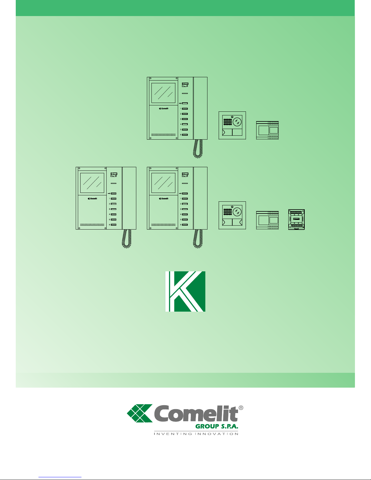
KIT VIDEO
BRAVO KIT VIDEO
VIDEO BRAVO KIT
VIDEO BRAVO KIT
TECHNICAL
MANUAL
MANUALE
TECNICO
MANUEL
TECHNIQUE
ENIT FR
Comelit Group S.p.A. - Via Don Arrigoni 5 - 24020 Rovetta S. Lorenzo BG Italy - tel. (+39) 0346 750 011 - fax (+39) 0346 71436
www.comelit.eu www.simplehome.eu [email protected] [email protected] [email protected]
Assistenza tecnica Italia 0346/750090
Commerciale Italia 0346/750091
Technical service abroad (+39) 0346750092
Export department (+39) 0346750093
MT KIT 04
Page 2
GROUP S.P.A.
MT KIT 04
IT
AVVERTENZE
• Effettuare l’installazione seguendo scrupolosamente le istruzioni fornite dal costruttore ed in conformità alle norme vigenti.
• Tutti gli apparecchi devono essere destinati esclusivamente all’uso per cui sono stati concepiti. Comelit Group S.p.A. declina ogni
responsabilità per un utilizzo improprio degli apparecchi, per modifiche effettuate da altri a qualunque titolo e scopo, per l’uso di accessori
e materiali non originali.
• Tutti i prodotti sono conformi alle prescrizioni delle direttive 2006/95/CE (che sostituisce la direttiva 73/23/CEE e successivi emendamenti)
e ciò è attestato dalla presenza della marcatura CE sugli stessi.
• Evitare di porre i fili di montante in prossimità di cavi di alimentazione (230/400V).
EN
WARNING
• Install the equipment by carefully following the instructions given by the manufacturer and in compliance with the legislation in force.
• All the equipment must only be used for the purpose it was designed for. Comelit Group S.p.A. does not assume responsibility for improper
use of the appliances, for modifications made by others for any reason or purpose, or for non-original accessories and materials.
• All products comply with the requirements of the 2006/95/CE directives (which replace the 73/23/CEE directives and subsequent
amendments), as certified by the CE mark on the products.
• Do not route the riser wires in proximity to power supply cables (230/400V).
FR
AVERTISSEMENTS
• Effectuer l’installation en suivant scrupuleusement les instructions fournies par le constructeur et conformément aux normes en vigueur.
• Tous les appareils doivent être strictement destinés à l’emploi pour lequel ils ont été conçus. La société COMELIT GROUP S.p.A. décline
toute responsabilité en cas de mauvais usage des appareils, pour des modifications effectuées par d’autres personnes pour n’importe
quelle raison et pour l’utilisation d’accessoires et matériaux non d’origine.
• Tous les produits sont conformes aux prescriptions de la directive 2006/95/CE (qui remplace la directive 73/23/CEE et amendements
successifs). Cela est attesté par la présence du marquage CE sur les produits.
• Eviter de placer les fils de montant à proximité des câbles d’alimentation (230/400 V).
Page 3

I T A L I A N O
MT KIT 04
SOMMARIO
•
GENERALITÀ pag. 2
•
POSTI ESTERNI
- Posto esterno Art. 4875/BK e Art. 4876/BK pag. 2
- Regolazione volume audio Art. 4875/BK e Art. 4876/BK pag. 2
- Caratteristiche tecniche alimentatore Art. 1205/B pag. 2
- Istruzione di installazione Art. 4875/BK, 4876/BK pag. 3
•
POSTI INTERNI
- Caratteristiche tecniche Monitor Art. B/W 5701 pag. 4
- Staffa di fissaggio del Monitor Art. 5714/K pag. 5
- Installazione monitor Art. 5701 a parete pag. 5
- Montaggio Monitor Art. 5701 sulla base da tavolo Art. 5712 pag. 6
- Procedura per togliere il Monitor e posizionamento etichetta pag. 6
- Istruzioni di installazione Scheda opzionale Art. 5733,
Art. 5734 pag. 7
- Istruzioni per installazione citofono Style Art. 2608,
2628 e 2610 pag. 8
- Citofono Style Art. 2608 pag. 9
- Citofono Style Art. 2628 pag. 10
- Citofono Style Art. 2610 pag. 11
•
INDICAZIONI GENERALI DI INSTALLAZIONE
E FUNZIONAMENTO
- Tabella cavi e distanze pag. 12
- Tabella impostazioni Art. 1216 pag. 13
•
IMPOSTAZIONI E DESCRIZIONE FUNZIONAMENTO
SISTEMA BRAVO KIT
- Impostazioni Staffa e Citofoni pag. 14
- Tabella di programmazione micro interruttori
per codice utente su staffe e citofoni pag. 15
- Impostazione staffa Art. 5714/K principale
o secondaria pag. 15
- Tabella impostazioni funzioni Staffa Art. 5714/K pag. 16
- Descrizione impostazioni e funzione pulsanti pag. 17
- Procedura selezione suoneria Monitor pag. 18
- Impostazione citofono opzionale Art. 2610 pag. 19
- Funzione Autoaccensione e Richiesta video pag. 19
- Programmazioni speciali Art. 4660/BK pag. 20
•
ESPANDIBILITÀ DEL SISTEMA BRAVO KIT
- Programmazione Art. 4660/BK pag. 21
•
DESCRIZIONE SCHEMI DI COLLEGAMENTO BRAVO KIT pag. 22
•
DESCRIZIONE VARIANTI DI COLLEGAMENTO
BRAVO KIT pag. 23
•
MESSA IN FUNZIONE/VERIFICA TENSIONI
DI IMPIANTO A RIPOSO pag. 72
BRAVO KIT VIDEO
MT KIT 04
1
•
SCHEMI DI COLLEGAMENTO
- BK/01 Schema base per kit monofamiliari Art. 8171 pag. 74
- BK/02B Schema base per kit bifamiliari Art. 8173
con collegamento in derivazione pag. 75
- BK/02A Schema base per kit bifamiliari Art. 8173
con collegamento in cascata pag. 76
- BK/03B Schema per kit bifamiliari Art. 8173 ampliati con
un secondo Art. 4876/BK. Collegamento in derivazione pag. 77
- BK/03A Schema per kit bifamiliari Art. 8173 ampliati
con un secondo Art. 4876/BK. Collegamento in cascata pag. 78
- BK/04B Schema per kit bifamiliari ampliati con un secondo
Art. 4876/BK, un’ulteriore monitor secondario e un citofono per
ciascuna unita’ familiare. Collegamento in derivazione pag. 79
- BK/04A Schema per kit bifamiliari ampliati con un secondo
Art. 4876/BK, un’ulteriore monitor principale e un citofono
per ciascuna unita’ familiare. Collegamento in cascata pag. 80
- BK/01A Schema per kit monofamiliare con alimentatore
aggiuntivo Art. 1395 pag. 81
•
VARIANTI DI COLLEGAMENTO
- BK/05 Utilizzo modulo telecamera scorporata
Art. 1259/A pag. 82
- SB2/AAQ Collegamento amplificatore video Art. 4833/A pag. 83
- BK/H Aggiunta di un monitor principale in parallelo,
collegamento in cascata pag. 83
- BK/I Aggiunta di un monitor principale in parallelo,
collegamento in derivazione pag. 84
- BK/C Collegamento in cascata di un monitor principale
e di un monitor secondario con lo stesso codice utente pag. 84
- BK/D Aggiunta di un citofono in parallelo in derivazione
dal montante pag. 85
- BK/AAB Collegamento citofoni aggiuntivi in derivazione
dal monitor pag. 85
- BK/AAA Collegamento citofoni aggiuntivi in cascata
dal monitor pag. 86
- BK/E Aggiunta pilotaggio luce esterna tramite Art. 1256 pag. 86
- BK/A Aggiunta attuatore Art. 1256 pag. 87
- BK/O Variante collegamento apriporta locale
temporizzato pag. 87
- SB2/AAK Connessione di dispositivi di ripetizione
di chiamata (Art. 1229 o Art. 1122/A) pag. 88
- GEN/AAB Utilizzo Art. 1232 per filtraggio disturbi
indotti sui morsetti S+ e S- pag. 88
- Variante A: Aggiunta pulsante di chiamata fuori porta pag. 89
- BK/P Utilizzo pulsante 1 per usi vari pag. 89
- BK/N Variante per utilizzo Morsetto LED 1 pag. 89
- BK/EN/100 Schema per connessione a porta principale
di 3 BRAVO KIT tramite Art. 4834/9 pag. 90
- BK/EN/101 Schema di connessione a porta principale
con centralino Art. 1998A (opzionale) di 30 BRAVO KIT
(massimo). Derivazione Bravo Kit da 1214/2 pag. 92
Page 4
I T A L I A N O
GROUP S.P.A.
MT KIT 04
2
GENERALITÀ
I Kit Video Citofonici Monofamiliare Art. 8171 e Bifamiliare
Art. 8173 sono utilizzabili in edifici civili o terziari dove è richiesto
un’efficace controllo dell’accesso a fronte di semplici operazioni di
installazione.
Infatti bastano 2 conduttori tra il posto esterno e il/i monitor interni
per attivare il sistema (chiamata, fonica, video, autoaccensione), più
due fili per alimentare a 12V AC il posto esterno e l’elettroserratura.
É disponibile inoltre una vasta gamma di accessori per risolvere
facilmente ogni esigenza d’impianto: infatti oltre a interessanti
acces s ori di tipo standard è possibile amplia r e l’impianto
aggiungendo Videocitofoni e/o Citofoni e/o posti esterni.
In questo modo si può raggiungere un massimo di due posti esterni
con tre p o s t i interni t r a C i t o f o n i e Vide o c i t o f o n i per la
configurazione monofamiliare e due posti esterni con sei posti
interni tra Citofoni e Videocitofoni (tre per Pulsante di chiamata) per
la configurazione bifamiliare.
Tramite opportuni impostazioni (come da tabella riportata a
pagina 16) è possibile effettuare comunicazioni intercomunicanti
monofamiliari (cioè tra utenti con il medesimo codice utente) e
comunicazioni intercomunicanti bifamiliari (cioè tra utenti che
non h anno il m edes i mo c o dic e ute n te) ut iliz z and o sia
Videocitofoni che Citofoni.
Più Kit possono essere connessi a una porta principale Simplebus
e/o a un centralino Art. 1998A.
Vedi pagina 23 per maggiori informazioni.
POSTI ESTERNI
Caratteristiche tecniche
Connessione al monitor con 2 fili per audio, video, apriporta e
chiamata più 2 fili per alimentazione da Art. 1205/B.
Telecamera orientabile ad alta sensibilità con sensore CCD 1/3”.
Illuminazione all’infrarosso (6 LED).
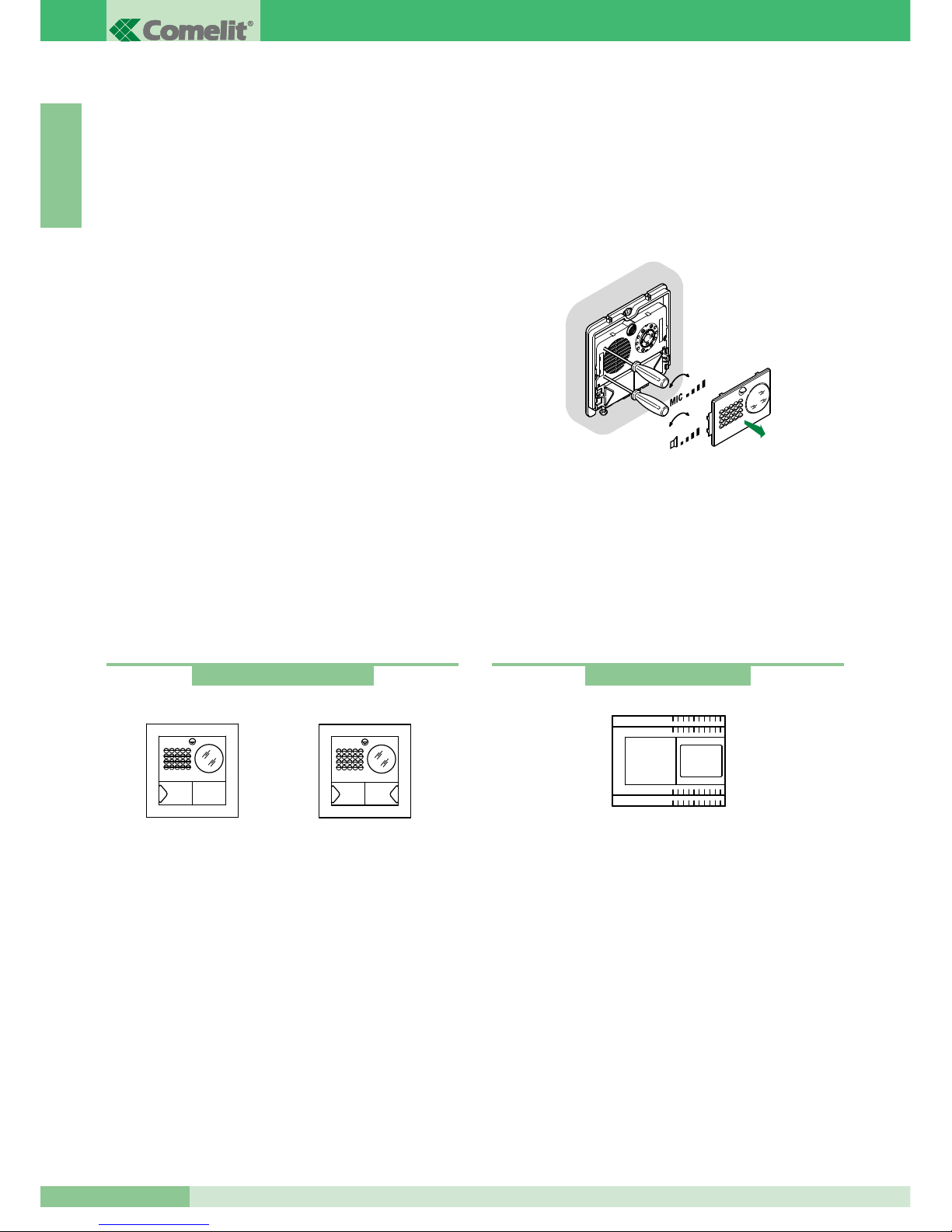
Regolazione volume microfono e altoparlante.
Pulsante di chiamata in alluminio con etichetta estraibile
anteriormente. Telaio porta moduli in alluminio pressofuso.
Dimensione scatola da incasso: 127x127x45 mm.
Il pulsante dell'articolo 4875/BK è impostato di fabbrica per
effettuare la chiamata all'indirizzo 1 mentre per l'articolo 4876/BK i
pulsanti sono impostati per effettuare chiamate agli indirizzi 1
(pulsante sinistro) e 2 (pulsante destro).
Dimensione posto esterno: 125x125 mm.
Descrizione morsettiera
LL connessione monitor (video, chiamata, fonica, apri porta)
SE-SE connessione elettroserratura
~ ~ alimentazione posto esterno
PR morsetto di programmazione
- morsetto negativo da utilizzare in fase di programmazione
S morsetto di programmazione
RTE ingresso apriporta locale temporizzato OCC., V+ (non usati)
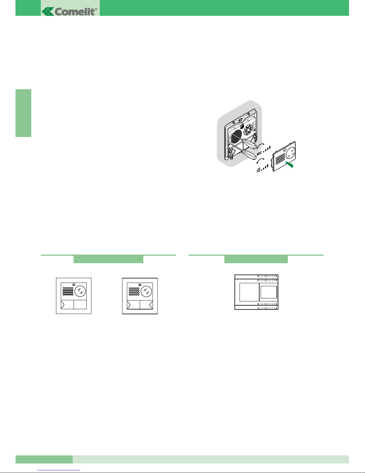
Regolazione volume audio
Il modulo del posto esterno è dotato di due regolazioni:
volume posto esterno, contraddistinto dal simbolo dell’altoparlante,
e regolazione del volume posto interno contraddistinto dal simbolo
del microfono.
Regolazione orientamento telecamera
Se è necessario modificare la regolazione della telecamera
procedere come indicato a pagina 3.
1 1 2
Art. 4875/BK - 4876/BK
Art. 4875/BK
Art. 4876/BK
+
-
+
-
Caratteristiche tecniche
Il trasformatore prevede 2 uscite: una per alimentare il posto
esterno e l’elettroserratura, l’altra per alimentare il monitor.
Dimensioni: 105x85x85 mm (6 moduli DIN).
Fusibile di protezione 500mA ritardato.
Descrizione morsettiera
AC230V ingresso tensione di rete
~~ uscita AC per posto esterno e elettroserratura
+ - uscita 20V DC di alimentazione del monitor
Art. 1205/B
Page 5
MT KIT 04
3
MT KIT 04
I T A L I A N O
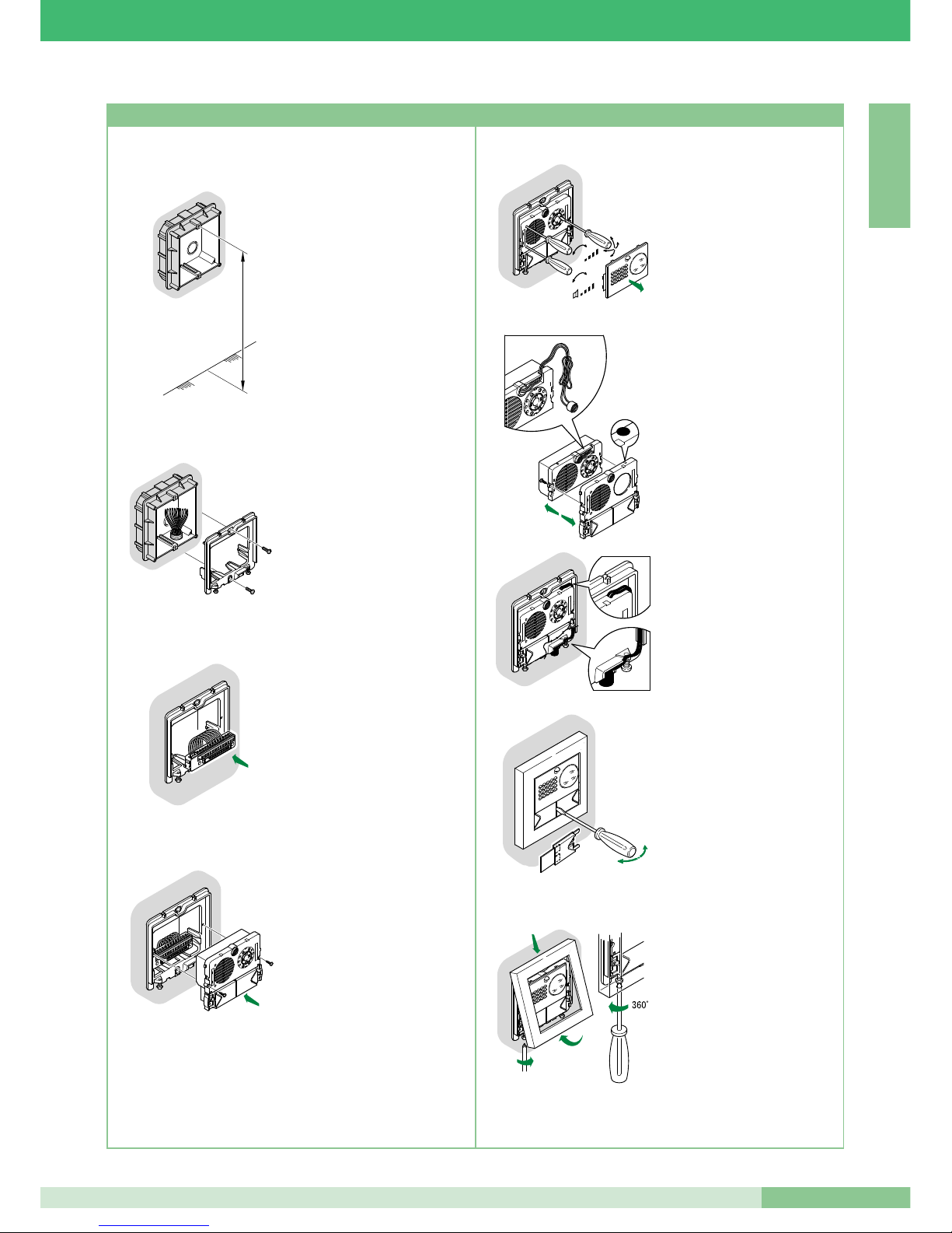
• Murare la scatola a 160÷165
cm dal pavimento finito,
in una zona agevole per la
ripresa del visitatore.
Possibilmente non controsole
o rivolte contro fonti di luce
diretta (lampade, superfici
riflettenti, ecc.)
• Fissare il telaio sulla scatola
da incasso utilizzando
le 2 viti in dotazione.
• Inserire la morsettiera ed
eseguire il collegamento
dei conduttori come da
schema.
• Inserire il modulo ad innesto
automatico sul morsetto
e fissarlo con le 2 viti in
dotazione.
160 - 165 cm
Carla
Rossi
+
-
+
-
Carla
Rossi
OPEN
1
2
3
CLOSE
+
-
+
-
MIC
4
5
2
3
1
• Togliere il frontalino in acciaio
inox per eseguire le regolazioni
dei volumi e l’orientamento
della telecamera.
N.B. Allentare leggermente le
quattro viti per sbloccare
l’orientamento della telecamera.
• Posizione alternativa del
microfono.
• Per togliere il cartellino
portanome inserire nella
fessura centrale la punta
del cacciavite ed estrarlo.
• A regolazioni ultimate fissare
la cornice agendo sulle 2 viti
inferiori.
N.B. Per togliere la cornice
svitare le 2 viti inferiori con una
rotazione di MAX 360°.
Istruzioni di installazione Art. 4875/BK, 4876/BK
Page 6
GROUP S.P.A.
MT KIT 04
4
I T A L I A N O
POSTI INTERNI
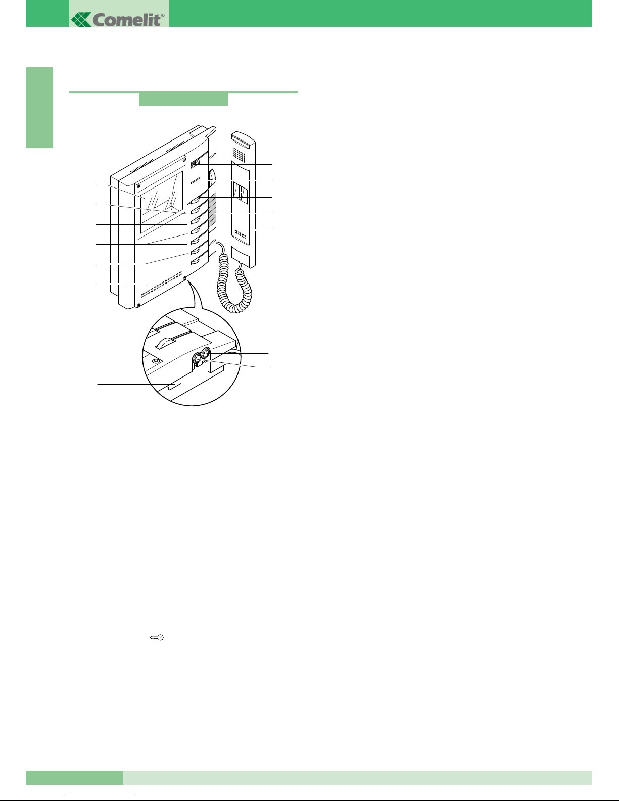
Caratteristiche tecniche Monitor bianco e nero Art. 5701
Monitor della serie Bravo di dimensioni 212x225x55 mm da
parete, di colore bianco RAL9003 (con frontale personalizzabile
secondo le preferenze dell’utente con il kit di personalizzazione
Art. 5727) e con schermo bianco e nero da 4’’.
Il Monitor è installabile anche su tavolo mediante l’apposito
supporto Art. 5712.
1. Regolazione volume chiamata / selettore funzione Privacy
(per servizio Privacy si intende l’esclusione della chiamata dal
posto esterno e da citofoni o videocitofoni intercomunicanti;
l’attivazione della funzione Privacy è evidenziata dalla
comparsa di un indicatore rosso a lato del selettore).
L’utente può selezionare la suoneria del Monitor preferita
come descritto a pagina 18.
2. Led di s egnal a zione (a ccens i one i n fu nzione della
configurazione adottata).
3. Pulsante Apriporta
.
4. Etichetta memo-pulsanti su cui è possibile riportare la
funzione dei pulsanti.
5. Cornetta Monitor (solleva r e la cornetta p e r iniziare la
comunicazione).
6. Schermo bianco e nero 4’’.
7. Frontalino di serie personalizzabile con Kit di personalizzazione.
8. Pulsante disponibile di serie, utilizzabile per usi vari (contatto
C.NO. 1A max) a seconda delle necessità di impianto;
rimuovendo CV3 e CV4 come riportato nella variante BK/P a
pag. 89.
9. Pulsante disponibile di serie.
10. Pulsanti opzionali (utilizzando la scheda Art. 5733 o Art.
5734) per attivazione funzioni supplementari .
11. Pulsanti opzionali (utilizzando la scheda Art. 5733) o Led di
segnalazione opzionali (utilizzando la scheda Art. 5734)
disponibili per diverse funzioni come riportato a pagina 16.
12 Manopola regolazione luminosità
(ruotare in senso orario per aumentare la luminosità).
13. Manopola regolazione intensità colore
(ruotare in senso orario per aumentare il valore).
14. Gancio di fissaggio.
È possibile utilizzare nella stessa unità familiare fino a un
massimo di 3 Monitor.
Art. 5701
6
1
2
3
4
5
6
8
4
5
3
2
1
9
10
11
7
12
13
14
Page 7
MT KIT 04
5
MT KIT 04
I T A L I A N O
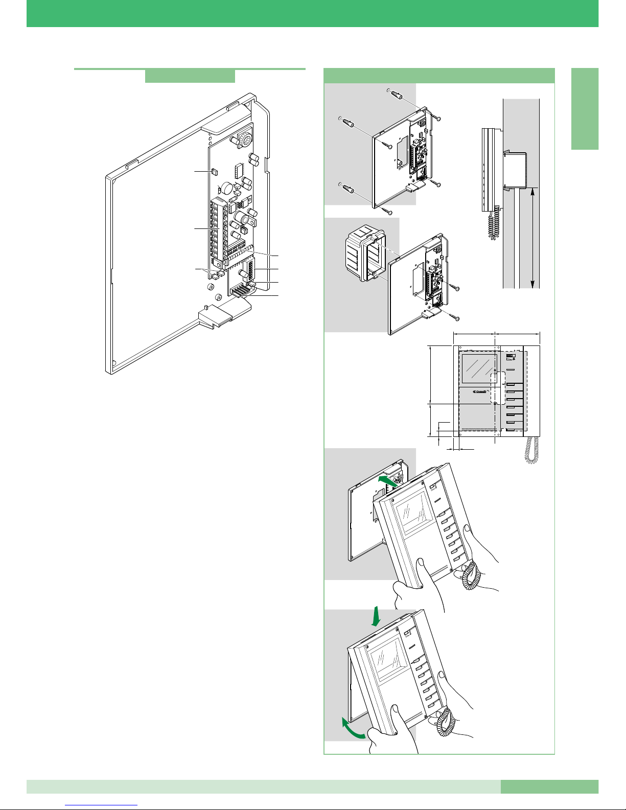
Staffa di fissaggio del monitor
La staffa di fissaggio Art. 5714/K consente l’installazione del
Monitor a muro o tramite la base da tavolo Art. 5712 (per maggiori
informazioni vedi pagina 4).
Caratteristiche tecniche
Dimensioni: 170 x 200 x 28 mm.
1. Connettore Staffa Monitor.
2. Morsetti di connessione impianto:
0 +20 morsetti per connessione con Art. 1205/B o Art. 1212/B.
L L morsetti di connessione linea Bus.
CFP CFP ingresso chiamata da piano.
P1 C1 Pulsante per usi vari. Per avere un contatto pulito C.NO.,
estrarre i jumper CV3 e CV4 (max 24V - 100mA).
S+ S- Morsetti per dispositivo ripetizione di chiamata.
LED1 Ingresso per gestione accensione Led di segnalazione
(in presenza di segnale su questo morsetto il Led
lampeggia; vedi variante BK/N a pag. 89).
3. Micro-interruttori di programmazione.
4. Jumper CV5 per la chiusura del segnale Video.
5. Jumper CV3 e CV4 (da estrarre per avere un contatto pulito
C.NO. sui morsetti P1C1).
6. Connettore per il collegamento della scheda supplementare
opzionale Art. 5733 o Art. 5734.
7. Jumper JP1. Usato per impostare la staffa del Monitor come
Principale o Secondaria (vedi pag. 15).
1 2 3
4
ON
5 6 7
8
DIP
4
2
1
5
6
7
3
Art. 5714/K
1
2
3
4
5
6
cm 10,2 cm 11
cm 14,4
cm 8,1
145 cm
CV2
CV7
CV1
CV6
CV5
CV3
CV4
1
2
3
4
5
6
CV2
CV7
CV1
CV6
CV5
CV3
CV4
1
2
3
4
5
6
1
2
cm 1,4
cm 1,4
12 3
4
ON
56 7
8
DIP
12 3
4
ON
56 7
8
DIP
Installazione monitor Art. 5701 a parete
Page 8
I T A L I A N O
GROUP S.P.A.
MT KIT 04
6
1
2
3
4
5
6
1
1
2
3
4
5
6
2
3
6
5
4
3
2
1
6
5
4
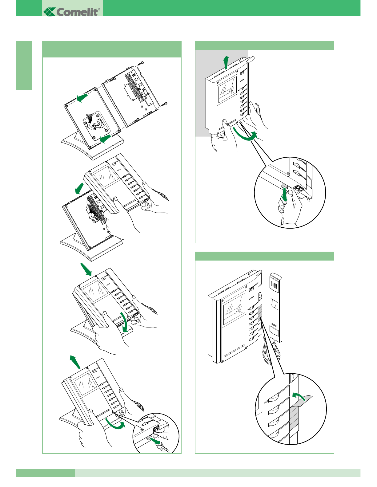
Montaggio Monitor Art. 5701 sulla base
da tavolo Art. 5712
1
2
3
4
5
6
3
2
1
Procedura per togliere il Monitor
1
2
3
4
5
6
1
2
Posizionamento etichetta sul monitor
Page 9
I T A L I A N O
MT KIT 04
MT KIT 04
7
1 2 3
4
ON
5 6 7
8
DIP
CV3
1 2 3 4
ON
5 6 7
DIP
CV4
1
2
1
2
3
1
4
5734
5734 !
2
1
6
3
4
5
6
5734 !
7
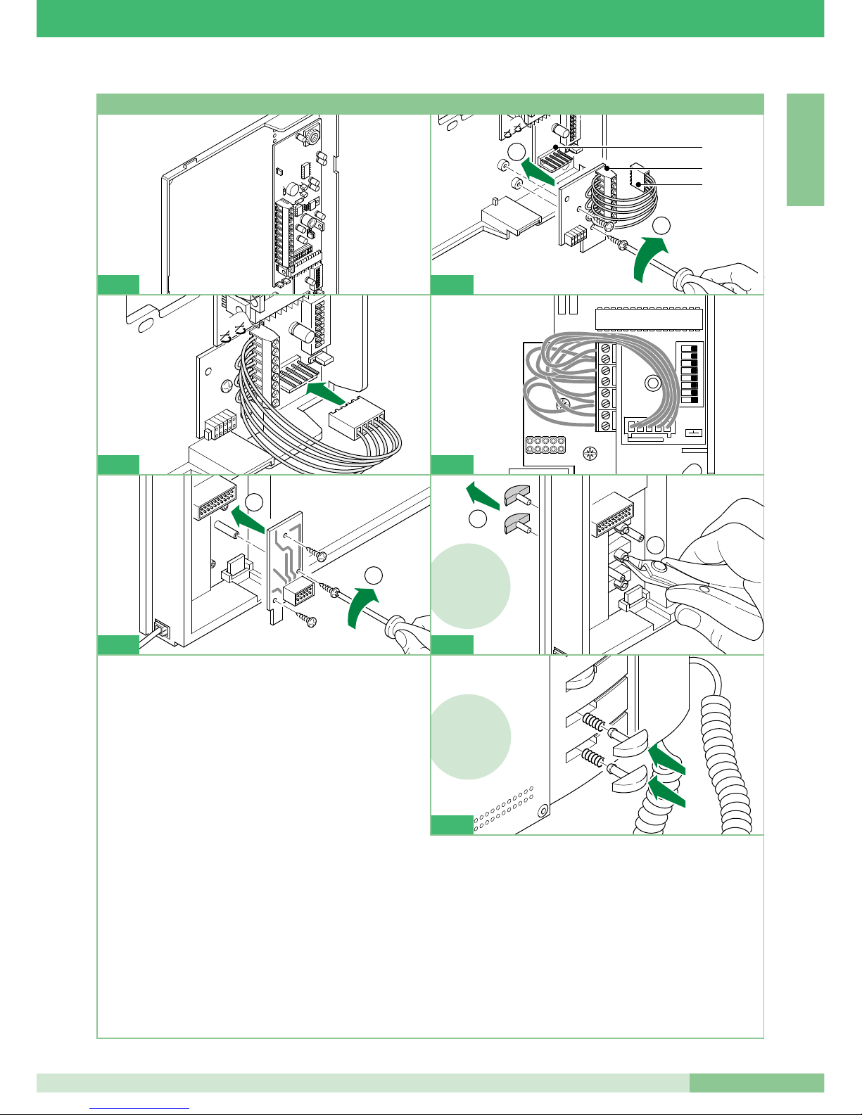
1 Estrarre la staffa e la scheda opzionale dalla propria
confezione.
2 Avvitare la scheda opzionale con le apposite viti sul supporto
plastico della staffa.
1. Morsettiera:
P3: Contatto Pulsante 3 del Monitor. *
C3: Contatto comune Pulsante 3 del Monitor *. Comune
principale da staffa Art. 5714/K (scollegare il filo verso il
connettore staffa per liberare tutti i contatti comuni).
P4: Contatto Pulsante 4 del Monitor. *
C4: Contatto comune Pulsante 4 del Monitor. *
+P5: Contatto Pulsante 5 del Monitor per Art. 5733*.
Ingresso positivo Led 5 per Art. 5734.
- C5: Contatto comune Pulsante 5 del Monitor per Art. 5733*.
Ingresso negativo Led 5 per Art. 5734.
+P6: Contatto Pulsante 6 del Monitor per Art. 5733*.
Ingresso positivo Led 6 per Art. 5734.
-C6: Contatto comune Pulsante 6 del Monitor per Art. 5733 *.
Ingresso negativo Led 6 per Art 5734.
2. Connettore maschio staffa.
3. Connettore femmina Art. 5733 o Art. 5734.
3 Collegare il connettore femmina della scheda opzionale al
connettore maschio posto sulla staffa.
4 Posizionare i fili tra la scheda opzionale e la staffa come
mostrato in figura.
5 Fissare con le apposite viti la scheda opzionale con connettore
sul retro del Monitor.
6 Solo per la scheda Opzionale Art. 5734: tagliare e rimuovere i
Pulsanti 5 e 6 del Monitor.
7 Solo per la scheda Opzionale Art. 5734: inserire i Pulsanti
trasparenti allegati alla confezione dell'articolo nelle posizioni
dei Pulsanti 5 e 6 come mostrato in figura.
*
Per utilizzare il Pulsante come contatto C.NO. (24V-100mA max) rimuovere il filo verso il connettore staffa e liberare il relativo comune.
CV3
1
2
3 4
ON
5
6
7 8
DIP
CV4
3
1
2
5
Istruzioni di installazione Scheda opzionale Art. 5733, Art. 5734
2
Page 10
GROUP S.P.A.
MT KIT 04
8
I T A L I A N O
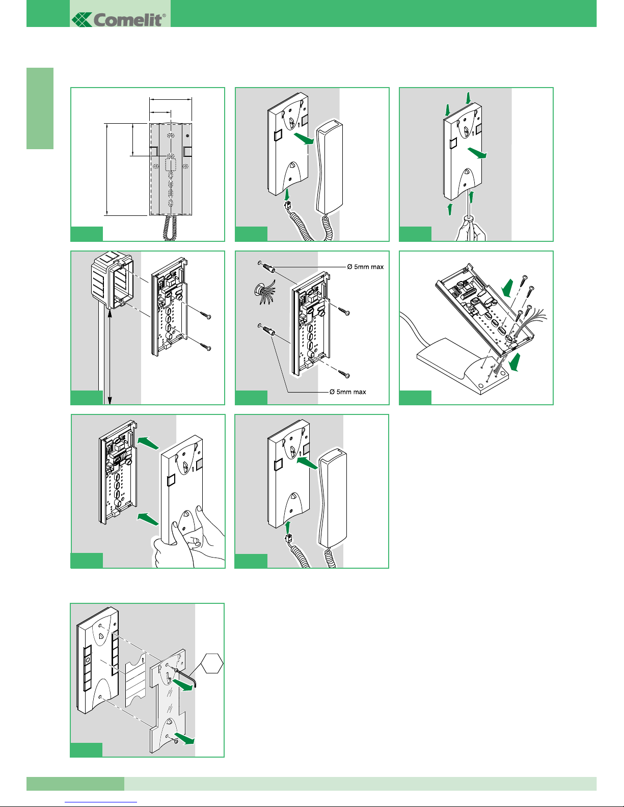
Istruzioni per installazione citofono Style Art. 2608, 2628 e 2610
Cover intercambiabile disponibile per gli Art. 2628 e Art. 2610
1
2
145 cm
4A 4B
95mm
47,5mm
75,5mm
215mm
1
1
1
1
1
2
3
1
4
2
2
5
6
2
4
6
1
3
5
7
9
2
8
CH2
7
1
2
4C
Page 11

MT KIT 04
9
MT KIT 04
I T A L I A N O
+
-
MIC
1 2 3 4 5 6 7 8
c
A
3
9
8
5
7
6
JP1
4
1
2
Citofono Basic con 2 pulsanti di serie.
Non è utilizzabile per sfruttare la funzione intercomunicante.
Il Citofono va montato sempre utilizzando l’Art. 1214/2 come
mostrato nello schema di collegamento BK/D a pagina 85.
1. Pulsante Apriporta .
2. Pulsante P1 chiamata centralino / attuatore generico / pulsante
per usi vari presente in morsettiera (P1 C1).
3. Selettore suoneria/servizio Privacy a 3 posizioni:
Posizione alto: Suoneria volume massimo.
Posizione centrale: Suoneria volume medio.
Posizione basso: Attivazione funzione privacy
(per servizio privacy si intende l’esclusione della suoneria di
chiamata dal posto esterno e centralino; l’attivazione della
funzione è evidenziata dalla comparsa di un indicatore rosso in
alto a destra).
4. Indicatore funzione Privacy.
5. Morsetti connessione impianto:
L L connessione alla linea bus.
CFP CFP ingresso chiamata da piano.
P1 C1 morsetti pulsante P1 C. NO. 24V 100mA dedicato a
servizi vari (rimuovere CV1 e CV2).
S+ S- morsetti per dispositivo ripetizione di chiamata.
6. JP1 jumper per selezionare la funzione Chiamata centralino
(posizione C) / Attuatore generico (posizione A) del pulsante P1
(vedi figura a lato).
7. CV1 CV2 jumper da rimuovere per avere contatto pulito C.
NO. sul pulsante P1.
8. Dip switch per impostazione codice utente (vedi tabella a pag. 15).
9. Trimmer regolazione volume microfono.
Pulire con un panno inumidito con acqua. Evitare Alcool e altri
prodotti aggressivi.
Citofono Style Art. 2608
Page 12

GROUP S.P.A.
MT KIT 04
10
I T A L I A N O
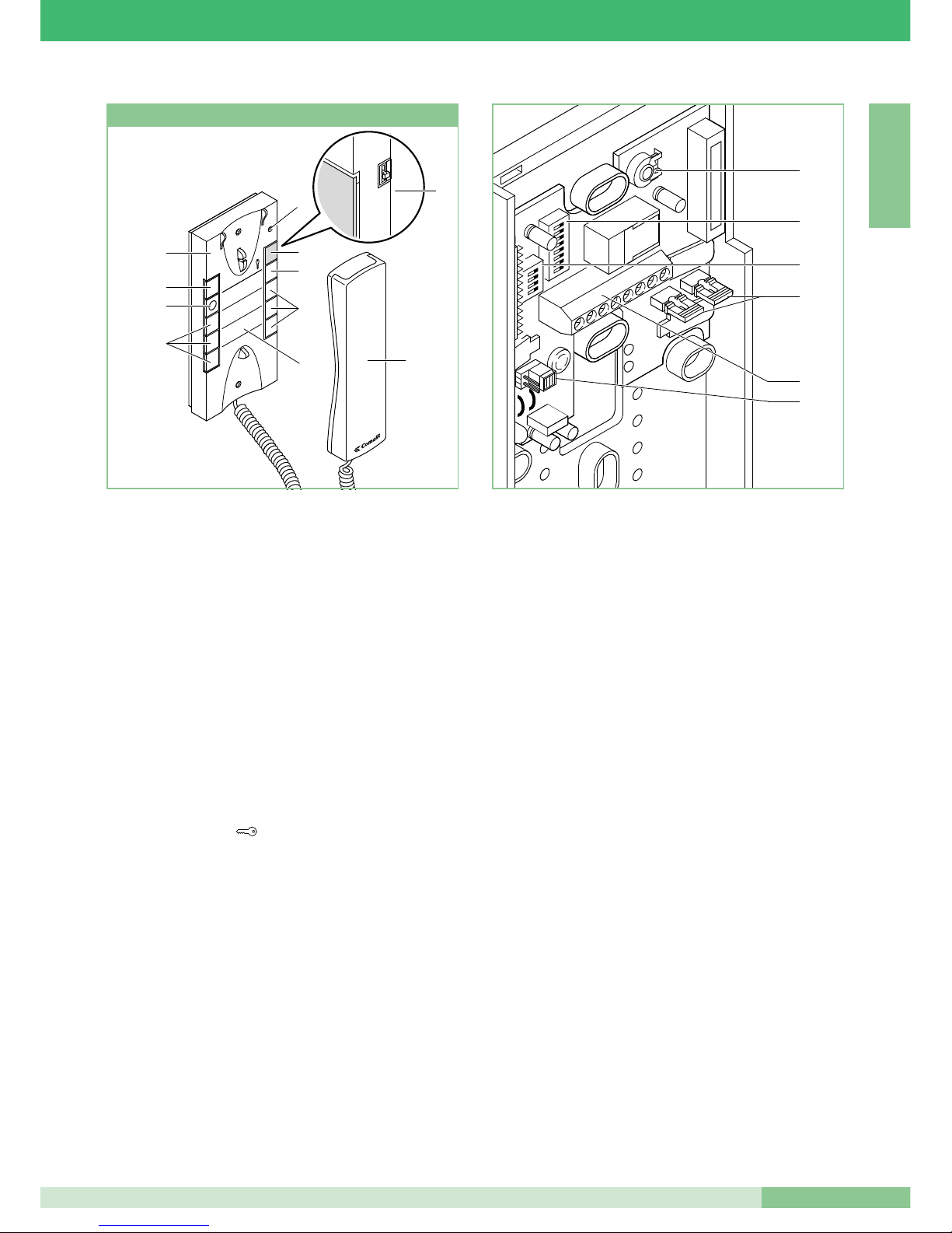
Citofono Elegance con funzioni e pulsanti supplementari.
Non è utilizzabile per sfruttare la funzione intercomunicante.
Il Citofono va montato sempre utilizzando l’Art. 1214/2 come
mostrato nello schema di collegamento BK/D a pagina 85.
Importante: per il corretto settaggio dell’Articolo in fase di
installazione all’interno di un sistema BRAVO KIT, fare
riferimento alla nota sotto.
1. Selettore suoneria/servizio Privacy a 3 posizioni:
Posizione alto: Suoneria volume massimo.
Posizione centrale: Suoneria volume medio.
Posizione basso : Attivazione funzione Privacy
(per servizio Privacy si intende l’esclusione della chiamata dal
posto esterno o centralino; l’attivazione della funzione Privacy è
evidenziata dalla comparsa di un indicatore rosso in alto a destra).
2. Indicatore funzione Privacy.
3. Pulsante 1 disponibile di serie per funzione Attuatore generico.
4. Pulsante Apriporta .
5. Pulsante 2 disponibile di serie per funzione chiamata a centralino.
6. Pulsante 3 per usi vari presente in morsettiera (P3 C3).
7. Pulsanti C. NO. o Led (MAX 3) o pzionali p er funzioni
supplementari. (A)
8. Cover intercambiabile Fig. 7 pag. 8.
9. Etichetta memo-pulsanti su cui è possibile riportare la funzione
dei pulsanti del citofono (da applicare sotto la cover
intercambiabile) Fig. 7 pag. 8.
10. Cornetta citofono (sollevare la cornetta per iniziare la
comunicazione).
(A) Pulsante disponibile con scheda opzionale Art. 1626.
Led di visualizzazione disponibile con scheda opzionale Art.
1627.
11. Morsetti connessione impianto:
L L connessione alla linea bus.
CFP CFP ingresso chiamata da piano.
P3 C3 morsetti pulsante P3 C. NO. 24V 100mA dedicato a
servizi vari.
S+ S- morsetti per dispositivo ripetizione di chiamata.
12. JP1 Jumper per la selezione tra modalità Simplebus 1 e
Simplebus 2.
13. Dip switch U2 per impostazione codice utente (vedi tabella a
pag. 15).
14. Trimmer regolazione volume microfono.
Pulire con un panno inumidito con acqua. Evitare Alcool e altri
prodotti aggressivi.
ATTENZIONE !
14
13
11
12
PER UTILIZZARE IL CITOFONO ART. 2628 IN IMPIANTI BRAVOKIT È NECESSARIO SPOSTARE
IL JUMPER JP1 IN POSIZIONE S1
S1
1
3
2
5
4
7
6
9
8
8
3
6
7
9
7
5
4
2
1
10
8
3
6
7
9
7
5
4
2
1
10
Citofono Style Art. 2628
JP1
Page 13
MT KIT 04
11
MT KIT 04
I T A L I A N O
1
3
2
5
4
7 6
9
8
Citofono Elegance con funzioni e pulsanti supplementari e
servizio intercomunicante.
L’Art. 2610 ha la possibilità, (mediante apposito settaggio) di
gestir e comunic azioni i n tercom u nican t i e altre fun z ioni
supplementari (vedi tabella riassuntiva riportata a pagina 16).
Il Citofono va montato sempre utilizzando l’Art. 1214/2 come
mostrato nello schema di collegamento BK/D a pagina 85.
1. Selettore suoneria/servizio Privacy a 3 posizioni:
Posizione alto: Suoneria volume massimo.
Posizione centrale: Suoneria volume medio.
Posizione basso : Attivazione funzione Privacy
(per servizio Privacy si intende l’esclusione della chiamata
dal posto esterno e centralino; l’attivazione della funzione
Privacy è evidenziata dalla comparsa di un indicatore rosso
in alto a destra).
2. Indicatore funzione Privacy.
3. Led di segnalazione (disponibile di serie).
4. Pulsante Apriporta .
5. Pulsante 1 disponibile di serie (programmabile con varie
funzioni, vedi tabella a pag. 19. Di fabbrica programmato
per funzione Attuatore generico).
6. Pulsante 2 disponibile di serie (liberabile, o programmabile
con varie funzioni, vedi tabella a pag. 19).
Di f abbr i ca p rogr amma to p e r f u nzi o ne c hiam a ta a
centralino.
7. Pulsanti C. NO. o Led (MAX 3) opzionali per funzioni
supplementari. (A)
8. Cover intercambiabile Fig 7 a pag. 8.
9. Etichetta memo-pulsanti su cui è possibile riportare la
funzione dei pulsanti del citofono (da applicare sotto la
cover intercambiabile), Fig. 7 a pag. 8.
10. Cornetta citofono (sollevare la cornetta per iniziare la
comunicazione).
(A) Pulsante disponibile con scheda opzionale Art. 1626.
Led di visualizzazione disponibile con scheda opzionale
Art. 1627.
11. Morsetti connessione impianto:
L L connessione alla linea bus.
CFP CFP ingresso chiamata da piano.
P2 C2 morsetti pulsante P2 C. NO. 24V 100mA dedicato a
servizi vari (rimuovere CV2 e CV3).
S+ S- morsetti per dispositivo ripetizione di chiamata.
12. JP1 Jumper per la selezione tra modalità Simplebus 1 e
Simplebus 2.
13. CV3 CV2 Jumper da rimuovere per avere il pulsante P2 C. NO.
14. Dip switch U2 per impostazione codice utente (vedi tabella a
pag 15).
15. Dip switch U4 per la programmazione del pulsanti P1 e P2
(vedi tabella a pag. 19).
16. Trimmer regolazione volume microfono.
Pulire con un panno inumidito con acqua. Evitare Alcool e altri
prodotti aggressivi.
16
14
15
13
11
12
Citofono Style Art. 2610
8
3
6
7
9
7
5
4
2
1
10
Page 14
I T A L I A N O
GROUP S.P.A.
MT KIT 04
12
Distanza massima tra posto
esterno 4875/BK o 4876/BK
e il 4833/A o 1214/2
più lontano. Distanza
massima tra 4833/A
e il 1214/2 più lontano
Distanza massima
tra il monitor e il 1214/2
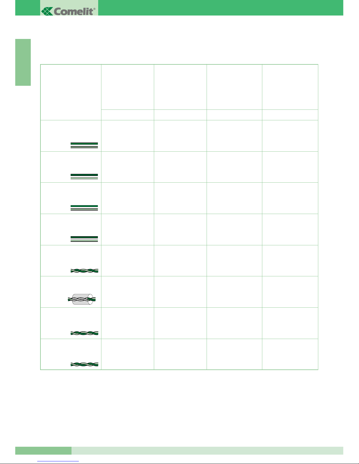
In questa sezione del manuale si riportano tutte le indicazioni riguardanti la fase di installazione del sistema BRAVO KIT.
La distanza massima totale tra il posto esterno e il monitor più lontano è 400 m.
INDICAZIONI GENERALI DI INSTALLAZIONE E FUNZIONAMENTO
Sezione
o tipo di cavo
Distanza massima
tra alimentatore 1205/B
o 1395 e posto esterno
4875/BK e 4876/BK
Distanza massima
tra alimentatore
1205/B o 1212/B
e monitor alimentato
A/G B/E C/F D
Cavo bifilare (sez. 0,5 mm
2
Ø 0,8 mm AWG 20)**
Cavo bifilare (sez. 1 mm
2
Ø 1,2 mm AWG 17)**
Cavo bifilare (sez. 1,5 mm
2
Ø 1,4 mm AWG 15)**
Cavo bifilare (sez. 2,5 mm
2
Ø 1,8 mm AWG 13)**
Doppino telefonico twistato
(sez. 0,28 mm
2
Ø 0,6 mm
AWG 23)*
Cavo intrecciato e schermato
(sez. 1 mm2 Ø 1,2 mm
AWG 17)*
UTP5 Cat 5 (sez. 0,2 mm
2
Ø 0,5 mm AWG 24)*
Cavo Comelit Art. 4576
e Art. 4578 (sez. 0,5 mm
2
Ø 0,8 mm AWG 20)*
* Nel caso si utilizzi un cavo multicoppiola usare una sola delle coppiole disponibili.
Nel caso sia necessario diminuire le cadute resistive utilizzare la singola coppiola come singolo filo.
** Nel caso si utilizzi un cavo multipolare usare solo due dei fili disponibili e non utilizzare mai fili in parallelo.
20 m
(65 feet)
40 m
(130 feet)
60 m
(195 feet)
100 m
(325 feet)
25 m
(85 feet)
50 m
(165 feet)
100 m
(325 feet)
150 m
(495 feet)
150 m
(495 feet)
150 m
(495 feet)
150 m
(495 feet)
150 m
(495 feet)
100 m
(325 feet)
150 m
(495 feet)
150 m
(495 feet)
40 m
(130 feet)
40 m
(130 feet)
40 m
(130 feet)
40 m
(130 feet)
20 m
(65 feet)
40 m
(130 feet)
50 m
(165 feet)
Page 15
MT KIT 04
13
MT KIT 04
I T A L I A N O
4875/BK
4876/BK
1205/B
1214/2
1216
C
A
B
D
4875/BK
4876/BK
1214/2
1216
F
F
4833/A
1212/B
E
1205/B
1395
4875/BK
4876/BK
G
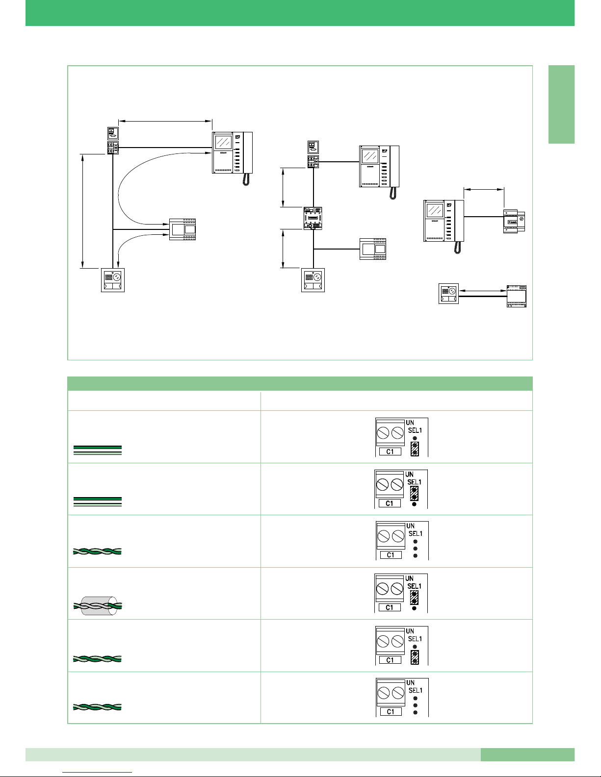
Tipo di cavo Impostazione Art. 1216
Cavo bifilare (sez. 1,5 mm2 Ø 1,4 mm AWG 15)
Cavo bifilare (sez. 1 mm2 Ø 1,2 mm AWG 17)
Doppino telefonico twistato
(sez. 0,28 mm2 Ø 0,6 mm AWG 23)
Cavo UTP5 cat 5
(sez. 0,2 mm2 Ø 0,5 mm AWG 24)
2
1
Cavo Comelit Art. 4576 e Art. 4578
(sez. 0,5 mm2 Ø 0,8 mm AWG 20)
Cavo bifilare
(sez. 0,5 mm2 Ø 0,8 mm AWG 20)
2
Cavo intrecciato e schermato
(sez. 1 mm2 Ø 1,2 mm AWG 17)
1
Tabella Impostazioni dell’Art. 1216 in funzione del tipo di cavo di connessione utilizzato
Page 16
I T A L I A N O
MT KIT 04
14
GROUP S.P.A.
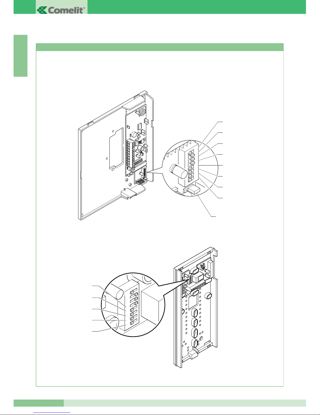
Impostazioni staffa Art. 5714/K e citofoni Style Art. 2608, 2628 e 2610
IMPOSTAZIONI E DESCRIZIONE FUNZIONAMENTO SISTEMA BRAVO KIT
La figura seguente mostra la posizione dei micro-interruttori e del Jumper JP1 della staffa 5714/K e dei micro-interruttori dei citofoni Style
Art. 2608, 2628 e 2610.
1 2 3 4 5 6 7 8
S1-5
S1-4
S1-3
S1-2
S1-1
1 2 3
4
ON
5 6 7
8
DIP
1 2 3
4
ON
5 6 7
8
DIP
S1-8
S1-7
S1-6
S1-4
S1-3
S1-2
S1-1
S1-5
JP1
Page 17

I T A L I A N O
15
MT KIT 04
MT KIT 04
I valori di S1-1, S1-2, S1-3, S1-4 e S1-5 definiscono l’indirizzo di chiamata.
Per la codifica sia delle staffe che dei citofoni fare riferimento alla seguente tabella.
ATTENZIONE: SUI CITOFONI 2608, 2628 E 2610 POSIZIONARE
SU OFF I DIP 6, 7, 8.
La chiamata intercomunicante bifamiliare (tra citofoni e/o
videocitofoni) è possibile solo se i due utenti sono impostati su
codici di chiamata contigui (contrassegnati dalla stessa lettera
AA…CC..YY nella tabella di programmazione dei Micro
interruttori riportata qui sopra).
Tabella di programmazione dei Micro interruttori per codice utente su Staffe e citofoni
ESEMPIO impostazione codice 20.
H 16 5
I 17 1,5
I 18 2,5
J 19 1,2,5
J 20 3,5
K 21 1,3,5
K 22 2,3,5
L 23 1,2,3,5
L 24 4,5
M 25 1,4,5
M 26 2,4,5
N 27 1,2,4,5
N 28 3,4,5
O 29 1,3,4,5
O 30 2,3,4,5
A 1 1
A 2 2
B 3 1,2
B 4 3
C 5 1,3
C 6 2,3
D 7 1,2,3
D 8 4
E 9 1,4
E 10 2,4
F 11 1,2,4
F 12 3,4
G 13 1,3,4
G 14 2,3,4
H 15 1,2,3,4
Riferimento per
intercomunicante Codice utente Micro interruttori su ON
bifamiliare
Riferimento per
intercomunicante Codice utente Micro interruttori su ON
bifamiliare
Impostazione staffa Art. 5714/K principale o secondaria
Principale
Secondaria
1 2 3
4
ON
5 6 7
8
DIP
1 2
ON
1
ON
Page 18
I T A L I A N O
GROUP S.P.A.
MT KIT 04
16
OFF
(0)
OFF
(0)
OFF
(0)
S1-6 S1-7 S1-8 Funzioni tasti
Pulsante
Pulsante 1
Pulsante 2
Pulsante 3
Pulsante 4
Pulsante 5
Pulsante 6
Apriporta
Attuatore / Pulsante Libero
Accensione interna / Richiesta Video
Chiamata a centralino
Chiamata intercomunicante Monofamiliare
Chiamata intercomunicante Bifamiliare
(1)
Gestione funzione Dottore
ON
(1)
OFF
(0)
OFF
(0)
Pulsante
Pulsante 1
Pulsante 2
Pulsante 3
Pulsante 4
Pulsante 5
Pulsante 6
Apriporta
Chiamata intercomunicante Monofamiliare
Chiamata intercomunicante Bifamiliare
Chiamata a centralino
Chiamata intercomunicante Monofamiliare
Chiamata intercomunicante Bifamiliare
(1)
Gestione funzione Dottore
OFF
(0)
ON
(1)
OFF
(0)
Pulsante
Pulsante 1
Pulsante 2
Pulsante 3
Pulsante 4
Pulsante 5
Pulsante 6
Apriporta
Chiamata intercomunicante Monofamiliare
Gestione funzione Dottore
Chiamata a centralino
Chiamata intercomunicante Monofamiliare
Chiamata intercomunicante Bifamiliare
(1)
Gestione funzione Dottore
ON
(1)
ON
(1)
OFF
(0)
Pulsante
Pulsante 1
Pulsante 2
Pulsante 3
Pulsante 4
Pulsante 5
Pulsante 6
Apriporta
Chiamata intercomunicante Bifamiliare
Gestione funzione Dottore
Chiamata a centralino
Chiamata intercomunicante Monofamiliare
Chiamata intercomunicante Bifamiliare
(1)
Gestione funzione Dottore
OFF
(0)
OFF
(0)
ON
(1)
Pulsante
Pulsante 1
Pulsante 2
Pulsante 3
Pulsante 4
Pulsante 5
Pulsante 6
Apriporta
Chiamata intercomunicante Monofamiliare
Accensione interna / Richiesta Video
Chiamata a centralino
Chiamata intercomunicante Monofamiliare
Chiamata intercomunicante Bifamiliare
(1)
Gestione funzione Dottore
ON
(1)
OFF
(0)
ON
(1)
Pulsante
Pulsante 1
Pulsante 2
Pulsante 3
Pulsante 4
Pulsante 5
Pulsante 6
Apriporta
Chiamata intercomunicante Bifamiliare
Accensione interna / Richiesta Video
Chiamata a centralino
Chiamata intercomunicante Monofamiliare
Chiamata intercomunicante Bifamiliare
(1)
Gestione funzione Dottore
OFF
(0)
ON
(1)
ON
(1)
Pulsante
Pulsante 1
Pulsante 2
Pulsante 3
Pulsante 4
Pulsante 5
Pulsante 6
Apriporta
Chiamata a centralino
Accensione interna / Richiesta Video
Chiamata a centralino
Chiamata intercomunicante Monofamiliare
Chiamata intercomunicante Bifamiliare
(1)
Gestione funzione Dottore
ON
(1)
ON
(1)
ON
(1)
Pulsante
Pulsante 1
Pulsante 2
Pulsante 3
Pulsante 4
Pulsante 5
Pulsante 6
Apriporta
Chiamata a centralino
Comando Attuatore
Chiamata a centralino
Chiamata intercomunicante Monofamiliare
Chiamata intercomunicante Bifamiliare
(1)
Gestione funzione Dottore
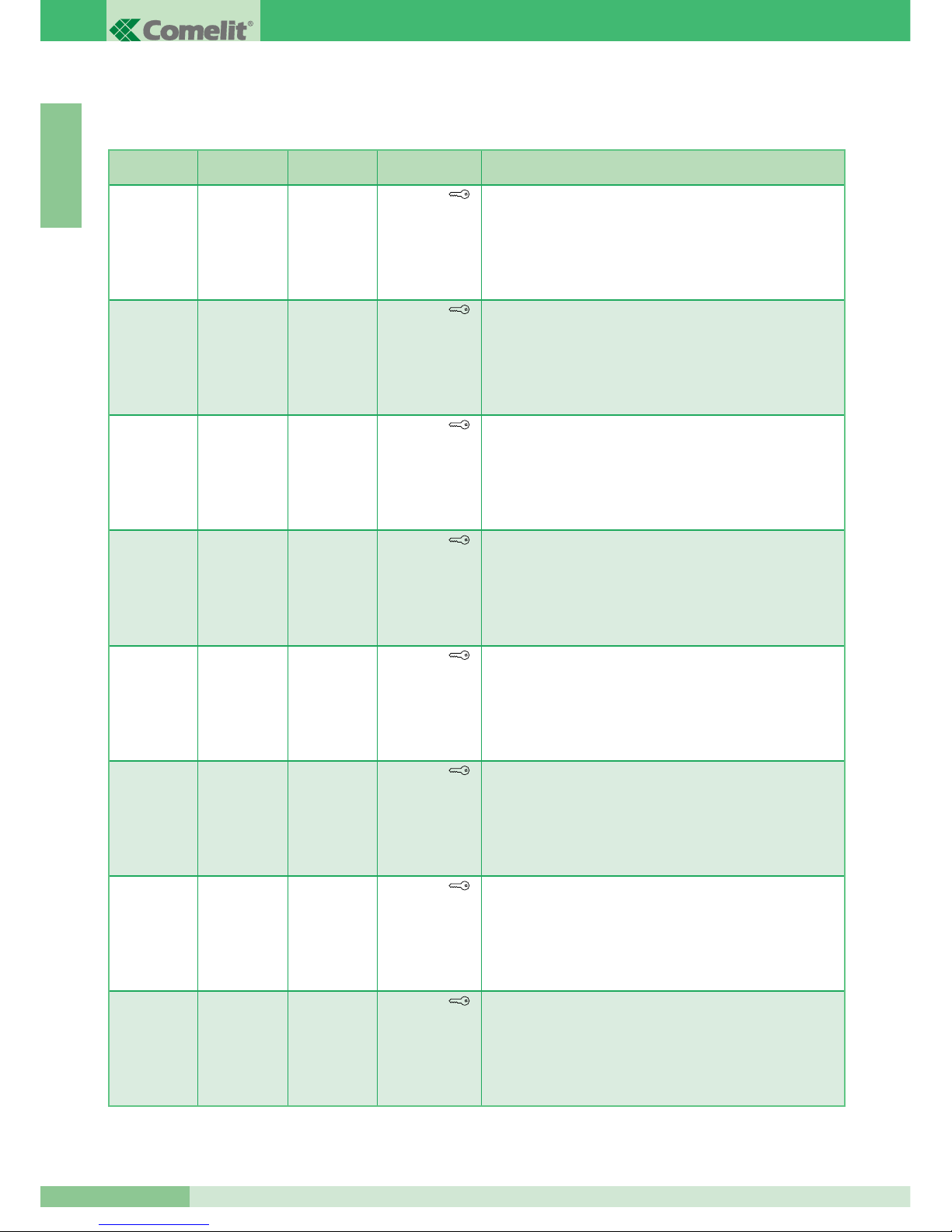
Il valore di S1-6, S1-7 e S1-8 (solo per staffa Art. 5714/K) definisce la modalità operativa in cui opererà il Sistema Bravo KIT come riportato
nella seguente tabella.
(1)
La chiamata intercomunicante bifamiliare (tra citofoni e/o videocitofoni) è possibile solo se i due utenti sono impostati su
codici di chiamata contigui (contrassegnati dalla stessa lettera AA…CC..YY nella tabella di programmazione dei Micro
interruttori riportata a pagina 15).
Page 19

I T A L I A N O
MT KIT 04
17
MT KIT 04
MICRO-INTERRUTTORI S1-1, S1-2, S1-3, S1-4 E S1-5
I valori dei micro-interruttori S1-1, S1-2, S1-3, S1-4 e S1-5
definiscono l’indirizzo di chiamata della staffa in oggetto nei
confronti del posto esterno di chiamata.
Per utilizzare la funzione di chiamata intercomunicante bifamiliare
gli utenti (citofoni e/o videocitofoni) devono essere impostati su
indirizzi di chiamata contigui contrassegnati nella tabella riportata
a pagina 15 con la stessa lettera (AA…CC….YY).
Funzionamento
• Il visitatore premendo il tasto di chiamata accende i LED
all’infrarosso per l’illuminazione del soggetto, aziona la suoneria
interna di chiamata (se la funzione privacy non è abilitata) e fa
apparire l’immagine sul/sui monitor principale/i per circa 60”.
Nel caso invece, si entri in comunicazione, la durata massima
della conversazione potrà essere di 90’’.
Al posto esterno si ha un tono di avvenuta chiamata; se in
impianti con 2 o più ingressi all'atto della chiamata, il posto
esterno emette un tono di occupato invece che la replica della
suoneria, significa che un'altra comunicazione è già in atto verso
un altro posto esterno.
In caso di cortocircuito persistente sulla linea bus il posto
esterno emette un tono di segnalazione intermittente.
• Al posto interno la conversazione avviene sollevando la cornetta.
• Il comando di luminosità è posto sul lato inferiore del Monitor
mentre il comando per la regolazione del volume suoneria o
attivazione funzione Privacy sulla parte alta.
• Il tasto contraddistinto dal simbolo della chiave sul Monitor
agisce sull’elettroserratura attivandola per circa 2 sec.
• L’autoaccensione del Monitor principale avviene premendo il
Pulsante 2 a funzione abilitata (vedi descrizione a pagina 19).
In impianti dotati di 2 posti esterni è possibile visualizzare
alternativamente l’immagine da un posto esterno o dall’altro
(funzione ‘’bascula’’) con successive pressioni del Pulsante 2.
Non è possibile auto accendere il Monitor durante un’altra
conversazione.
• Per le funzionalità intercomunicanti del Sistema BRAVO KIT,
fare riferimento alla pagina 16.
• Per la programmazione di indirizzi utente diversi da quelli
impostati di fabbrica (1 e 2) fare riferimento a pag. 21.
Monitor supplementari principali o secondari
L’impostazione di JP1 definisce se la staffa in oggetto verrà gestita
come principale o come secondaria. Il posto esterno può gestire
fino a un massimo di 3 Videocitofoni o Citofoni per Pulsante di
chiamata. Quando dal posto esterno si effettua una chiamata, il
monitor che il sistema accenderà sarà quello del Videocitofono
principale.
Gli altri eventuali monitor secondari della medesima unità familiare
resteranno spenti. Rispondendo alla chiamata del posto esterno da
un Videocitofono secondario, l'immagine viene automaticamente
visualizzata sul Monitor.
A questo punto il monitor del Videocitofono principale verrà spento
e l’immagine verrà visualizzata sul monitor del Videocitofono di cui
è stato premuto il Pulsante 2 - richiesta video.
Anche senza sollevare la cornetta si ha la possibilità di visualizzare
l’immagine trasmessa dal posto esterno, sempre premendo il
Pulsante 2 - richiesta video.
Nella configurazione classica di BRAVO KIT, quindi, si possono
avere al massimo 2 Videocitofoni secondari e 1 Videocitofono
principale per Pulsante di chiamata tutti alimentati dallo stesso
Art. 1205/B (Variante BK/C pag. 84).
Vi è la possibilità di gestire fino a 3 Videocitofoni principali
all’interno della stessa unità familiare (cioè impostati sul medesimo
codice utente). In questa particolare configurazione, i Videocitofoni
principali addizionali dovranno essere alimentati ognuno
dall’apposito Art. 1212/B (Variante BK/H e BK/I pag. 83, 84).
Alla chiamata del posto esterno, l’immagine verrà visualizzata su
ognuno dei Videocitofoni principali connessi al sistema.
Ricordiamo che comunque, anche con l’utilizzo dell’Art. 1212/B, il
numero massimo di Videocitofoni collegabili per la medesima unità
familiare è di 3. Per nessun Citofono opzionale è necessaria
un’alimentazione dedicata.
S1-6, S1-7, S1-8
Impostazione della modalità di funzionamento BRAVO KIT
La tabella riportata a pagina 16 mostra le funzioni dei singoli
pulsanti del Monitor in funzione di come vengono impostati i microinterruttori S1-6, S1-7, S1-8.
Si ricorda che il Pulsante , il Pulsante 1 e il Pulsante 2 sono
di serie mentre il Pulsante 3, il Pulsante 4, il Pulsante 5 e il
Pulsante 6 sono opzionali utilizzando la scheda Art. 5733.
Vi è inoltre la possibilità, utilizzando l’Art. 5734, di avere a
disposizione i Pulsanti 3 e Pulsante 4 e due led di segnalazione
nelle posizioni del Pulsante 5 e del Pulsante 6.
Questi l e d di segn a l a z i o n e potranno e s s e r e utilizz a t i
dall’installatore per varie esigenze di impianto e non saranno gestiti
in modo automatico dalla staffa del Monitor.
Descrizione funzioni Pulsanti
Apriporta La pressione del Pulsante Apriporta attiva la
serratura connessa al posto esterno.
Attuatore La pression e del Pulsan t e impostat o nella
modalità Attuatore permette l’attivazione dell’Art. 1256 che può
essere utilizzato ad esempio per attivare l’apertura di cancelli,
porte basculanti o per l'attivazione del modulo telecamere
cicliche Art. 1259/A.
Pulsante Libero L’indicazione Pulsante libero indica la
possibilità di utilizzare il Pulsante come contatto C.NO. in
morsettiera, mediante opportune impostazioni come illustrato nella
variante BK/P a pagina 89.
Autoaccensione / Richiesta Video La pressione del Pulsante
2 impostato in questa modalità, permette di visualizzare sullo
schermo del Monitor l’immagine trasmessa dal posto esterno
anche se non è stata effettuata nessuna chiamata.
Page 20
GROUP S.P.A.
MT KIT 04
18
I T A L I A N O
Per l'utilizzo e l'abilitazione del servizio vedi variante BK/P a
pagina 89. In impianti dotati di due posti esterni, è possibile
visualizzare alternativamente l’immagine da un posto esterno o
dall’altro (funzione ‘’bascula’’) con successive pressioni del
Pulsante.
Su Monitor secondari il Pulsante 2 ha anche la funzione di
richiesta video (per maggiori informazioni vedere a pagina 19).
Chiamata a centralino La pressione del Pulsante impostato in
questa modalità permette di inviare una chiamata al Centralino di
portineria dell’impianto.
Chiamata intercomunicante Monofamiliare La pressione del
Pulsante impostato in questa modalità permette di inviare una
chiamata agli altri apparecchi (Videocitofoni e/o Citofoni) impostati
sullo stesso indirizzo di chiamata.
Il ricevente della chiamata alzando la cornetta entra così in
comunicazione con il chiamante.
Riagganciando la cornetta la comunicazione viene terminata.
Una chiamata da posto esterno è comunque sempre prioritaria
rispetto ad una comunicazione intercomunicante. In questo caso gli
utenti che si trovano già in conversazione sentiranno in cornetta un
tono simile a quello di chiamata se quest’ultima è indirizzata a loro
o un triplice tono di segnalazione in caso contrario.
Per rispondere alla chiamata da posto esterno è sufficiente
sollevare la cornetta da qualunque apparecchio libero o
riagganciare e sollevare la cornetta da un apparecchio impegnato
nella comunicazione intercomunicante.
L’attivazione della comunicazione con il posto esterno interrompe
la conversazione intercomunicante precedentemente in corso.
Una chiamata intercomunicante non è prioritaria rispetto ad una
conversazione/chiamata con il posto esterno.
In questo caso, durante un tentativo di chiamata intercomunicante,
il LED di segnalazione lampeggerà per alcuni secondi per
segnalare che il sistema è occupato.
Chiamata intercomunicante Bifamiliare La pressione del
Pulsante impostato in questa modalità permette di inviare una
chiamata agli apparecchi (Videocitofoni e/o Citofoni) impostati
sull’indirizzo di chiamata Bifamiliare rispetto al proprio, come
indicato nella tabella riportata a pagina 15.
Il ricevente della chiamata alzando la cornetta entra così in
comunicazione con il chiamante. Riagganciando la cornetta la
comunicazione viene terminata.
Una chiamata da posto esterno è comunque sempre prioritaria
rispetto ad una comunicazione intercomunicante.
In questo caso gli utenti che si trovano già in conversazione sentiranno
in cornetta un tono simile a quello di chiamata se quest’ultima è
indirizzata a loro o un triplice tono di segnalazione in caso contrario.
Per rispondere alla chiamata da posto esterno è sufficiente
sollevare la cornetta da qualunque apparecchio libero o
riagganciare e sollevare la cornetta da un apparecchio impegnato
nella comunicazione intercomunicante.
L’attivazione della comunicazione con il posto esterno interrompe
la conversazione intercomunicante precedentemente in corso.
Una chiamata intercomunicante non è prioritaria rispetto ad una
conversazione/chiamata con il posto esterno.
In questo caso, durante un tentativo di chiamata intercomunicante,
il LED di segnalazione lampeggerà per alcuni secondi per
segnalare che il sistema è occupato.
Gestione funzione Dottore La funzione Dottore permette
l’azionamento automatico dell’apriporta su chiamata all’indirizzo del
Videocitofono e/o Citofono dove la funzione è stata attivata, da
parte del posto esterno.
A funzione attivata il led di segnalazione r imane acceso.
L’abilitazione o la disabilitazione della funzione Dottore avviene
premendo per 2 secondi il pulsante impostato per tale funzione.
Operazioni per selezionare la suoneria Monitor
L’utente può selezionare la suoneria del Monitor tra una lista di
suonerie disponibili, seguendo la seguente procedura:
(1) Tenere premuto il Pulsante fino a che non verrà emesso
un suono di conferma (l’operazione è possibile solo con
l’impianto in situazione di riposo; in caso contrario il led di
segnalazione lampeggerà per avvisare l’utente).
(2) Premere e rilasciare il Pulsante :
1 volta (viene emesso un tono di conferma) per modificare la
suoneria di chiamata da posto esterno.
2 volte (vengono emessi 2 toni di conferma) per modificare la
suoneria da centralino.
3 volte (vengono emessi 3 toni di conferma) per modificare la
suoneria del campanello di piano.
Ulteriori pressioni del Pulsante ripetono la sequenza
appena descritta.
Dopo l’ultima pressione del Pulsante attendere un suono
di conferma selezione, prima di passare alla fase seguente.
(3) Premere e rilasciare il Pulsante per scorrere in sequenza
le varie suonerie disponibili. Nel caso si voglia riascoltare più
volte la stessa suoneria mantenere premuto il Pulsante .
(4) Sollevare e riagganciare la cornetta per confermare la scelta
dell’ultima suoneria ascoltata e per uscire (in qualunque
momento) dalla modalità di variazione suoneria Monitor.
All’uscita dalla modalità di variazione suoneria Monitor verrà
emesso un suono di conferma. A questo punto il Videocitofono
riprende il suo normale funzionamento.
Page 21
MT KIT 04
19
MT KIT 04
I T A L I A N O
Impostazione citofono (opzionale) Art. 2610
Nel caso si decida di ampliare il sistema BRAVO KIT con
l’aggiunta di un Citofono opzionale Art. 2610, qui di seguito è
riportata la tabella necessaria per definire le funzionalità che il
Citofono dovrà eseguire.
DIP 1 DIP 2 DIP3 DIP 4 Funzione tasto 1 Funzione tasto 2
0 0 0 0
Attuatore generico Chiamata a centralino
1
0 0 0
Chiamata a centralino Inter. Monofamiliare
0
1
0 0
Chiamata a centralino Inter. Bifamiliare
1 1
0 0
Attuatore generico Inter. Monofamiliare
0 0
1
0
Attuatore generico Inter. Bifamiliare
1
0
1
0
Dottore Chiamata a centralino
0
1 1
0
Dottore Attuatore generico
1 1 1
0
Dottore Inter. Monofamiliare
0 0 0
1 Dottore Inter. Bifamiliare
1
0 0
1 Inter. Monofamiliare Inter. Bifamiliare
0
1
0
1 Chiamata a centralino Autoaccensione
1 1
0
1 Attuatore generico Autoaccensione
0 0
1 1 Dottore Autoaccensione
1
0
1 1 Inter. Monofamiliare Autoaccensione
0
1 1 1 Inter. Bifamiliare Autoaccensione
2
ON
U4
4
3
1
1
3
2
5
4
7
6
9
8
P1
P2
Funzione Autoaccensione (solo per impianti con 1 o 2
ingressi) su monitor con staffe Art. 5714/K impostate come
Principali (vedi JP1 di figura, in posizione P). La funzione di
Autoaccensione deve essere abilitata.
Abilitare/disabilitare la funzione Autoaccensione: per abilitare
la funzione è necessario tener premuto il pulsante 2 del monitor
(prestare attenzione alla modalità BRAVO KIT impostata
mediante i micro interruttori di programazione) per un tempo
superiore a 4 sec. All’avvenuta impostazione si sente, portando
la cornetta all’orecchio, un duplice tono di conferma.
Per disabilitare tener premuto lo stesso pulsante per un tempo
superiore a 4 sec. In questo caso si sente, portando la cornetta
all’orecchio, un singolo tono di conferma.
Utilizzo dell’ autoaccensione: l’accensione del monitor avviene
(se la funzione è stata abilitata) premendo e rilasciando
immediatamente il Pulsante 2.
Richiesta Video su monitor con staffe Art. 5714/K impostate
come Secondario (vedi JP1 di figura, in posizione S).
La funzione di Richiesta video non richiede abilitazione; essa
permette di accendere un monitor in seguito ad una chiamata
da posto esterno per l’utente.
Utilizzo della funzione Richiesta Video: l’accensione del
monitor avviene premendo e rilasciando immediatamente il
Pulsante 2 (prestare attenzione alla modalità BRAVO KIT
impostata mediante i micro interruttori di programmazione).
Funzione Autoaccensione e Richiesta Video
1 2 3
4
ON
5 6 7
8
DIP
JP1
1
2
3
4
5
6
2
1 2 3
4
ON
5 6 7
8
DIP
JP1
1
2
3
4
5
6
2
Page 22
GROUP S.P.A.
MT KIT 04
20
I T A L I A N O
Programmazioni speciali Art. 4660/BK
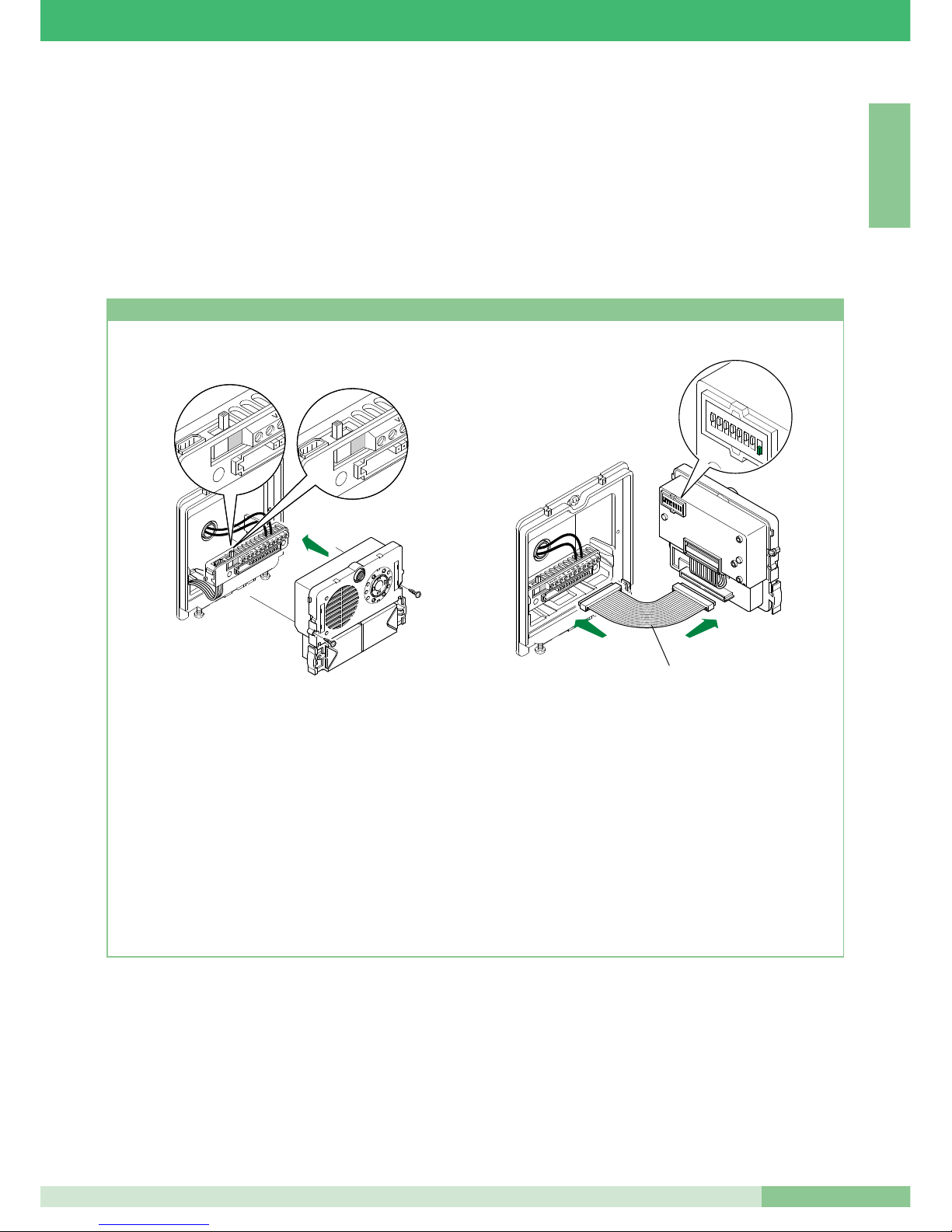
Sull’Art. 4660/BK è possibile effettuare una serie di programmazioni
speciali in funzione delle varie esigenze di impianto.
1. Sulla morsettiera degli articoli 4660/BK spostare l’interruttore in
posizione di programmazione (quadrato rosso) (Figura 1A) .
2. Impostare sui micro interruttori dell'articolo (Figura 2) il codice
relativo alla funzione che si desidera programmare. Usare
come riferimento la tabella sotto.
3. Sulla morsettiera degli articoli 4660/BK connette r e il
morsetto S con – (Figura 3).
4. Attendere che venga emesso un tono di conferma avvenuta
programmazione e rimuovere il cavallotto tra il morsetto S e -.
5. Al termine della procedura assicurarsi di avere rimesso
l’interruttore in posizione di riposo (quadrato bianco) (Figura 2A),
di aver rimosso il cavallotto tra S e - e riposizionare tutti i micro
interruttori in posizione OFF (0) come mostrato in Figura 4.
Per effettuare un'altra programmazione speciale, ripetere le
operazioni descritte dal punto 1 al punto 5.
1
2 3
4 5
6 7 8
ON
DIP
Art. 3309
Fig. 1A Fig. 2A
Fig. 1
Fig. 3
Fig. 2
Fig. 4
Dip switch su ON
Numero di riferimento
configurazione
Tempo attesa reset 10 secondi (impostazione di fabbrica) 1,2,5,6,7,8 243
Tempo attesa reset 1 secondo 3,5,6,7,8 244
Disattivazione tono conferma serratura e impostazione tempo serratura 2 sec. (impostazioni di fabbrica) 1,3,5,6,7,8 245
Attivazione tono conferma serratura 2,3,5,6,7,8 246
Tempo serratura 8 secondi 1,2,3,5,6,7,8 247
Invio chiamata singola (impostazione di fabbrica) 4,5,6,7,8 248
Invio chiamata ripetuta 3 volte 1,4,5,6,7,8 249
Comando apriporta normalmente aperto (NO) (impostazione di fabbrica) 2,4,5,6,7,8 250
Comando Apriporta normalmente chiuso (NC) 1,2,4,5,6,7,8 251
Apriporta attivo anche in assenza di chiamata (impostazione di fabbrica) 3,4,5,6,7,8 252
Apriporta abilitato solo per l'utente chiamato 1,3,4,5,6,7,8 253
Ripristino di tutte le impostazioni di fabbrica 2,3,4,5,6,7,8 254
Page 23
MT KIT 04
21
MT KIT 04
I T A L I A N O
ESPANDIBILITÀ DEL SISTEMA BRAVO KIT
dell'Art. 4660/BK a bordo dell'Art. 4875/BK o 4876/BK come
descritto nella seguente procedura e le staffe 5714/K con il codice
corrispondente (come riferimento vedi tabella a pagina 15).
Per maggiori informazioni sull'integrazione dei BRAVO KIT in
impianti Simp l ebus e per la prog r a mmazione dell a porta
principale (Art. 4660) fare riferimento al catalogo Simplebus 2
(Catalogo no. 66) al manuale tecnico MT/SB2/01 e al foglio
tecnico FT/SB/16.
Negli schemi BK/EN/100 e BK/EN/101 a pag. 90, 92 riportati
nella sezione A di questo manuale viene mostrata una possibile
configurazione d’impianto che offre la possibilità di gestire fino a
un massimo di 30 BRAVO KIT da parte di un Art. 4660 posto per
esempio all’ingresso di un complesso residenziale.
Utilizzando questi schemi di impianto è possibile chiamare uno
dei BRAVO KIT dall'ingresso principale dotato di Art. 4660.
In questa configurazione è necessario programmare i pulsanti
Programmazione Art. 4660/BK
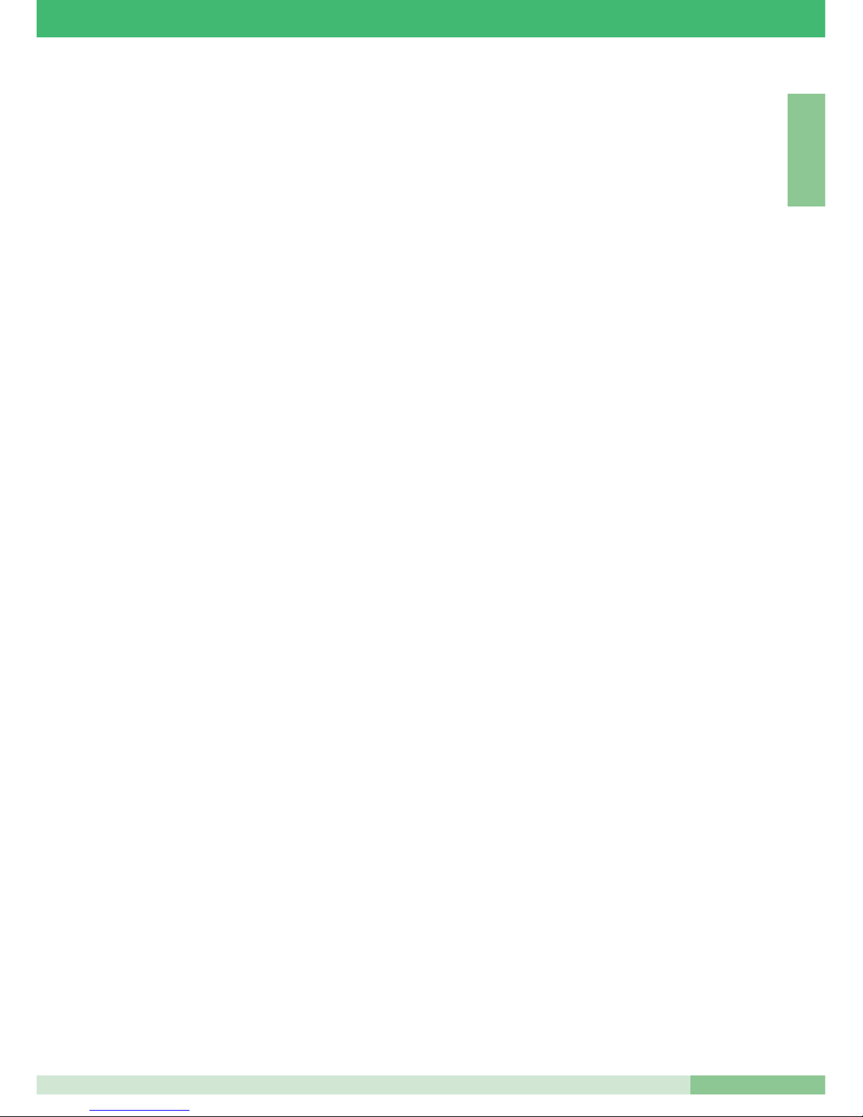
1. Sulla morsettiera del modulo Art. 4660/BK ollegare
l’alimentazione su ~ ~, spostare l’interruttore in posizione di
programmazione (rosso) (vedi figura 1A).
Connettere la morsettiera al modulo Art. 4660/BK assemblato
come indicato precedentemente.
N.B.: per il collegamento tra la morsettiera e il modulo Art.
4660/BK in fase di programmazione è possibile usare il
cavetto Art. 3309 disponibile come accessorio opzionale
(figura 2).
2. Impostare il Dip switch posto sul retro del modulo audio-
video con lo stesso codice assegnato al citofono o monitor
secondo la corrisponde n z a d e scritta nella tabella di
programmazione a pagina 15.
3. Premere il pulsante che si desidera associare alla chiamata
del citofono o monitor. L’avvenuta programmazione viene
segnalata con un tono di conferma.
4. Al termine d e l l a programmazione riposizionare
l’interruttore in posizione di standby (bianco) (figura 2A).
1
2
3
4
5
6 7
8
ON
DIP
Art. 3309
Fig. 1A Fig. 2A
Fig. 1 Fig. 2
Page 24

GROUP S.P.A.
MT KIT 04
22
I T A L I A N O
namento, fare riferimento alle indicazioni riportate a pagina 12.
Configurazione Micro-interruttori (di seguito chiamati DIP) sulla staffa:
DIP 1 su ON - DIP 2, DIP 3, DIP 4, DIP 5 su OFF:
impostano il codice utente numero 1 per chiamata da posto esterno bifamiliare (4876/BK).
DIP 2 su ON - DIP 1, DIP 3, DIP 4, DIP 5 su OFF:
impostano il codice utente numero 2 per chiamata da posto esterno bifamiliare (4876/BK).
DIP 6, DIP 7, DIP 8: a seconda delle funzioni desiderate.
JP1 in posizione P: imposta la staffa del monitor come principale.
Fare riferimento alla tabella nelle pagine precedenti con le indicazioni per le impostazioni delle possibili configurazioni. Acquistando
uno scambio Art. 1224A e un secondo posto esterno
Art. 4876/BK è possibile ampliare l’impianto bifamiliare con due posti
esterni. La stessa operazione si può realizzare con i kit monofamiliari.
In impianti dotati di 2 Art. 4876/BK è possibile visualizzare alternativamente l’immagine da un posto esterno o dall’altro (funzione ‘’bascula’’)
con successive pressioni del pulsante di autoaccensione. Terminare il
montante con morsetto Art. 1216 come riportato sullo schema. La
distanza massima tra l’Art. 1214/2 e il monitor è di 20 metri.
Schema BK/03A Pag. 78
Collegamento in cascata
Schema base per kit bifamiliari Art. 8173.
Per i conduttori da utilizzare e per le distanze massime di funzionamento, fare riferimento alle indicazioni riportate a pagina 12.
Configurazione Micro-interruttori (di seguito chiamati DIP) sulla staffa:
DIP 1 su ON - DIP 2, DIP 3, DIP 4, DIP 5 su OFF:
impostano il codice utente numero 1 per chiamata da posto esterno bifamiliare (4876/BK).
DIP 2 su ON - DIP 1, DIP 3, DIP 4, DIP 5 su OFF:
impostano il codice utente numero 2 per chiamata da posto esterno bifamiliare (4876/BK).
DIP 6, DIP 7, DIP 8: a seconda delle funzioni desiderate.
JP1 in posizione P: imposta la staffa del monitor come principale.
Fare riferimento alla tabella nelle pagine precedenti con le indicazioni per le impostazioni delle possibili configurazioni. Acquistando uno
scambio Art. 1224A e un secondo posto esterno Art. 4876/BK è possibile ampliare l’impianto bifamiliare con due posti esterni. La stessa
operazione si può realizzare con il kit monofamiliare. In impianti
dotati di 2 Art. 4876/BK è possibile visualizzare alternativamente
l’immagine da un posto esterno o dall’altro (funzione ‘’bascula’’) con
successive pressioni del Pulsante 2 richiesta video. Terminare il
montante con morsetto Art. 1216 come riportato sullo schema.
Schema per kit bifamiliari ampliati con un secondo
Art. 4876/BK, un’ulteriore monitor secondario e un
citofono per ciascuna unità familiare.
Schema BK/04B Pag. 79
Collegamento in derivazione
Schema per kit bifamiliari ampliati con un secondo
Art. 4876/BK, un’ulteriore monitor principale e un
citofono per ciascuna unita’ familiare.
Schema BK/04A Pag. 80
Collegamento in cascata
Schema per kit monofamiliare con alimentatore
aggiuntivo Art. 1395
Schema BK/01A Pag. 81
DESCRIZIONE SCHEMI DI COLLEGAMENTO BRAVO KIT
Schema base per kit monofamiliari Art. 8171
Schema BK/01 Pag. 74
Schema base per kit monofamiliari Art. 8171.
Per i conduttori da utilizzare e per le distanze massime di funzionamento, fare riferimento alle indicazioni riportate a pagina 12.
Configurazione Micro-interruttori (di seguito chiamati DIP) sulla staffa:
DIP 1 su ON - DIP 2, DIP 3, DIP 4, DIP 5 su OFF:
impostano il codice utente numero 1 per chiamata da posto esterno
monofamiliare (4875/BK).
DIP 6, DIP 7, DIP 8: a seconda delle funzioni desiderate.
JP1 in posizione P: imposta la staffa del monitor come principale.
Fare riferimento alla tabella a pag. 15 con le indicazioni per le impostazioni delle possibili configurazioni.
Schema base per kit bifamiliari Art. 8173
Schema BK/02B Pag. 75
Collegamento in derivazione
Schema base per kit bifamiliari Art. 8173.
Per i conduttori da utilizzare e per le distanze massime di funzionamento, fare riferimento alle indicazioni riportate a pagina 12.
Configurazione Micro-interruttori (di seguito chiamati DIP) sulla staffa:
DIP 1 su ON - DIP 2, DIP 3, DIP 4, DIP 5 su OFF:
impostano il codice utente numero 1 per chiamata da posto esterno
bifamiliare (4876/BK).
DIP 2 su ON - DIP 1, DIP 3, DIP 4, DIP 5 su OFF:
impostano il codice utente numero 2 per chiamata da posto esterno
bifamiliare ( 4876/BK).
DIP 6, DIP 7, DIP 8: a seconda delle funzioni desiderate.
JP1 in posizione P: imposta la staffa del monitor come principale.
Fare riferimento alla tabella a pag. 15 con le indicazioni per le impostazioni delle possibili configurazioni. Terminare il montante con
morsetto Art. 1216 come riportato sullo schema.
La distanza massima tra l’Art. 1214/2 e il monitor è di 20 metri.
Schema BK/02A Pag. 76
Collegamento in cascata
Schema base per kit bifamiliari Art. 8173.
Per i conduttori da utilizzare e per le distanze massime di funzionamento, fare riferimento alle indicazioni riportate a pagina 12.
Configurazione Micro-interruttori (di seguito chiamati DIP) sulla staffa:
DIP 1 su ON - DIP 2, DIP 3, DIP 4, DIP 5 su OFF:
impostano il codice utente numero 1 per chiamata da posto esterno
bifamiliare (4876/BK).
DIP 2 su ON - DIP 1, DIP 3, DIP 4, DIP 5 su OFF:
impostano il codice utente numero 2 per chiamata da posto esterno
bifamiliare (4876/BK).
DIP 6, DIP 7, DIP 8: a seconda delle funzioni desiderate.
JP1 in posizione P: imposta la staffa del monitor come principale.
Fare riferimento alla tabella a pag. 15 con le indicazioni per le impostazioni delle possibili configurazioni. Terminare il montante con
morsetto Art. 1216 come riportato nello schema.
Schema per kit bifamiliari Art. 8173 ampliati con un
secondo 4876/BK
Schema BK/03B Pag. 77
Collegamento in derivazione
Schema base per kit bifamiliari Art. 8173.
Per i conduttori da utilizzare e per le distanze massime di funzio-
Page 25
MT KIT 04
23
MT KIT 04
I T A L I A N O
possibile comandare il relè a bordo dell’attuatore tramite i
pulsanti dedicati sul monitor e/o citofono.
Portata relè attuatore: 10A. Per le modalità d’uso dell’Art. 1256
rifarsi al foglio tecnico FT SB2 02 dello stesso articolo.
Variante collegamento apriporta locale temporizzato
Schema BK/O Pag. 87
Connessione di dispositivi di ripetizione di chiamata
(Art. 1229 o Art. 1122/A)
Schema SB2/AAK Pag. 88
La somma totale del numero di posti interni con stesso codice
utente e del numero di dispositivi di ripetizione chiamata collegati
ai suddetti posti interni non può superare il numero di 4.
Connettere un solo dispositivo di ripetizione chiamata per ogni
posto interno.
La distanza MAX del collegamento tra posto interno e dispositivo
di ripetizione chiamata è di 20m; utilizzare cavo schermato per il
collegamento e non far passare i cavi in prossimità di carichi
induttivi pesanti o cavi di alimentazione (230V / 400V).
In caso di connessione di carichi indut t i v i si co n s i glia la
connessione di una capacità di 470nF in parallelo ai contatti C-NO
dell’Art. 1122/A.
Nel c aso s i pre sent a sse u n di s tur b o au d io in dott o dal
collegamento dei fili morsetti S+ S-, utilizzare l'Art. 1232 (vedi
schema GEN/AAB a pag. 88).
Utilizzo Art. 1232 per filtraggio disturbi indotti sui
morsetti S+ e S-
Schema GEN/AAB Pag. 88
Variante A:
Aggiunta pulsante di chiamata fuori porta Pag. 89
Si può aggi unge r e un morse t to di chiam ata fuor i porta
collegandosi ai morsetti CFP e CFP della staffa 5714/K.
La chiamata fuori porta ha un tono differenziato rispetto a quella
da posto esterno. In caso di più citofoni o staffe con lo stesso
codice utente, collegare il pulsante CFP su uno solo; tutti i
dispositivi suoneranno contemporaneamente.
Utilizzo pulsante 1 per usi vari
Schema BK/P Pag. 89
Variante per utilizzo Morsetto LED 1
Schema BK/N Pag. 89
Schema per connessione a porta principale di 3
BRAVO KIT tramite Art. 4834/9
Schema BK/EN/100 Pag. 90
Schema di connessione a porta principale con centralino
Art. 1998A (opzionale) di 30 BRAVO KIT (massimo).
Derivazione Bravo Kit da 1214/2
Schema BK/EN/101 Pag. 92
DESCRIZIONE VARIANTI DI COLLEGAMENTO BRAVO KIT
Utilizzo modulo telecamera scorporata Art. 1259/A
Schema BK/05 Pag. 82
Collegamento amplificatore video Art. 4833/A
Schema SB2/AAQ Pag. 83
Aggiunta di un monitor principale in parallelo
Schema BK/H Pag. 83
Collegamento in cascata
É possibile ampliare l’impianto base fino ad avere un massimo di tre
utenti interni per ogni Pulsante di chiamata del posto esterno. Per
aggiungere un monitor sono necessari gli Art. 5714/K (staffa), 5701
(monitor) e il trasformatore di alimentazione Art. 1212/B. Impostare i
micro-interruttori con il codice utente secondo la tabella a pag. 15.
Cablare le due staffe in collegamento in cascata entra-esci (vedi
schema) oppure utilizzare i morsetti 1214/2 per derivarsi dal
montante (vedi schema BK/I a pag. 84).
Schema BK/I Pag. 84
Collegamento in derivazione
Collegamento in cascata di un monitor principale e di
un monitor secondario con lo stesso codice utente
Schema BK/C Pag. 84
In questo schema si evidenzia la possibilità di collegare due
monitor (principale e secondario) in cascata tra loro e derivati dal
montante con Art. 1214/2.
In questa configurazione su chiamata dal posto esterno si avrà
l’a ccensione del solo mo nitor principale e la possibilità di
accendere il monitor secondario con la pressione del Pulsante 2
(richiesta video). Su chiamata dal posto esterno la suoneria si
attiva su ambedue i monitor.
Aggiunta di un citofono in parallelo in derivazione
dal montante
Schema BK/D Pag. 85
Collegamento citofoni aggiuntivi in derivazione dal monitor
Schema BK/AAB Pag. 85
Collegamento citofoni aggiuntivi in cascata dal monitor
Schema BK/AAA Pag. 86
Aggiunta pilotaggio luce esterna tramite Art. 1256
Schema BK/E Pag. 86
Inserendo l’Art.1256 in parallelo ai morsetti LL della staffa 5714/K,
si può ottenere il consenso necessario per pilotare una lampada
esterna sincrona all’accensione del monitor.
In questo modo, sia su chiamata che sul comando di
autoaccensione, è possibile illuminare in modo ottimale il soggetto
al posto esterno. Per le modalità d’uso dell’Art. 1256 rifarsi al foglio
tecnico FT SB2 02 dello stesso articolo.
Aggiunta attuatore Art. 1256
Schema BK/A Pag. 87
Inserendo l’Art. 1256 in parallelo ai morsetti della staffa 5714/K è
Page 26

Page 27
MT KIT 04
SUMMARY
•
GENERAL INFORMATION page 26
•
EXTERNAL UNITS
- External unit Art. 4875/BK and Art. 4876/BK page 26
- Audio volume adjustment Art. 4875/BK and Art. 4876/BK page 26
- Technical characteristics of power supply Art. 1205/B page 26
- Installation instructions Art. 4875/BK, 4876/BK page 27
•
INTERNAL UNITS
- Technical characteristics of B/W Monitor Art. 5701 page 28
- Monitor fixing bracket Art. 5714/K page 29
- Wall-mounting of monitor Art. 5701 page 29
- Mounting Monitor Art. 5701 on desk base Art. 5712 page 30
- Procedure for removing Monitor and positioning label page 30
- Optional card installation instructions Art. 5733, Art. 5734 page 31
- Installation instructions for Style telephone Art. 2608,
2628 and 2610 page 32
- Style telephone Art. 2608 page 33
- Style telephone Art. 2628 page 34
- Style telephone Art. 2610 page 35
•
GENERAL INSTALLATION AND OPERATION INSTRUCTIONS
- Table of cables and distances page 36
- Table of settings Art. 1216 page 37
•
SETTINGS AND DESCRIPTION OF BRAVO KIT SYSTEM
OPERATION
- Telephone and Bracket settings page 38
- Table of microswitch programming
by user code on brackets and telephones page 39
- Setting of bracket Art. 5714/K main
or secondary page 39
- Table of bracket function settings Art. 5714/K page 40
- Description of pushbutton functions and settings page 41
- Monitor ringtone selection procedure page 42
- Setting telephone (optional) Art. 2610 page 43
- Self ignition and Video Request function page 43
- Special programming Art. 4660/BK page 44
•
BRAVO KIT SYSTEM EXPANDABILITY
- Programming Art. 4660/BK page 45
•
DESCRIPTION OF BRAVO KIT CONNECTION DIAGRAMSpage 46
•
DESCRIPTION OF
BRAVO KIT CONNECTION VARIANTS page 47
•
SWITCHING ON/VOLTAGE CHECK WITH SYSTEM
AT REST page 72
VIDEO BRAVO KIT
MT KIT 04
25
E N G L I S H
•
CONNECTION DIAGRAMS
- BK/01 Main diagram for single-residence kits Art. 8171. page 74
- BK/02B Main diagram for two-residence kits Art. 8173
with branch connection. page 75
- BK/02A Main diagram for two-residence kits Art. 8173
with connection in cascade. page 76
- BK/03B Diagram for two-residence kits Art. 8173
extended with a second Art. 4876/BK. Branch connection. page 77
- BK/03A Diagram for two-residence kits Art. 8173
extended with a second Art. 4876/BK.
Connection in cascade. page 78
- BK/04B Diagram for two-residence kits extended with
a second Art. 4876/BK, an additional secondary monitor and
an telephone for each residence unit. Branch connection. page 79
- BK/04A Diagram for two-residence kits extended with a
second Art. 4876/BK, an additional main monitor and an
telephone for each residence unit. Connection in cascade. page 80
- BK/01A Diagram for single-residence kit with additional
power supply Art. 1395. page 81
•
CONNECTION VARIANTS
- BK/05 Use of remote camera module Art. 1259/A. page 82
- SB2/AAQ Connection of video amplifier Art. 4833/A. page 83
- BK/H Addition of a main monitor in parallel,
connection in cascade. page 83
- BK/I Addition of a main monitor in parallel,
branch connection. page 84
- BK/C Connection in cascade of a main monitor and a
secondary monitor with the same user code. page 84
- BK/D Addition of an telephone in parallel with branch
connection from riser. page 85
- BK/AAB Connection of additional telephones
with branch connection from monitor. page 85
- BK/AAA Connection of additional telephones
with cascade connection from monitor. page 86
- BK/E Addition of external light control using Art. 1256. page 86
- BK/A Addition of actuator Art. 1256. page 87
- BK/O Timed local door lock release connection variant. page 87
- SB2/AAK Connection of call repetition devices
(Art. 1229 or Art. 1122/A). page 88
- GEN/AAB Use of Art. 1232 to filter induced interference
on terminals S+ and S-. page 88
- VARIANT A: Addition of door call pushbutton. page 89
- BK/P Use of pushbutton 1 for various purposes. page 89
- BK/N Variant for use of terminal LED 1 page 89
- BK/EN/100 Diagram for connection of 3 BRAVO KITS
to main entrance panel using Art. 4834/9. page 90
- BK/EN/101 Diagram for connection of 30 BRAVO KITS
(max.) to main entrance panel with switchboard Art.
1998A (optional). Bravo Kit branch from 1214/2. page 92
Page 28
GROUP S.P.A.
MT KIT 04
26
E N G L I S H
GENERAL INFORMATION
The Single-residence Video Door Entry Kits Art. 8171 and Tworesidence Video Door Entry Kits Art. 8173 can be used in
residential or service sector buildings where effective access
control and simple installation operations are required.
In fact, just 2 wires between the external unit and the internal
monitor/s are required to activate the system (calls, intercom, video
automatic switch-on), plus two wires to provide the 12Vac power to
the external unit and electric lock.
A wide range of accessories to meet the needs of any type of
system is also available: as well as interesting standard
accessories, the system can also be extended by adding Video
doorphones and/or Telephones and/or external units.
In this way it is possible to have a maximum of two external units
with three internal units including Telephones and Video
doorphones for the single-residence configuration, and two external
units with six internal units including Telephones and Video
doorphones (three for each call Button) for the two-residence
configuration.
By means of appropriate settings (according to the table on
page 40) single-residence intercommunications (i.e. between
us e rs ha vi ng th e sam e use r cod e ) and tw o- re si de n ce
intercommunications (i.e. between users not having the same
user code) are possible using Video doorphones as well as
Telephones.
Several Kits can be connected to a Simplebus main entrance panel
and/or a switchboard Art. 1998A.
See page 47 for further information.
EXTERNAL UNITS
Technical characteristics
Connection to monitor with 2 wires for audio, video, door lock
release and call plus 2 wires for power supply from Art. 1205/B.
High sensitivity, adjustable camera with 1/3” CCD sensor. Infrared
lighting (6 LEDs).
Microphone and speaker volume adjustment. Aluminium call button
with label removable from the front. Die-cast aluminium moduleholder frame.
Flush-mounted box dimensions: 127x127x45 mm.
The pushbutton of article 4875/BK is factory-set to call address 1,
whereas for article 4876/BK the pushbuttons are set to call
addresses 1 (left pushbutton) and 2 (right pushbutton).
External unit dimensions: 125x125 mm.
Description of terminal block
LL monitor connection (video, call, audio, door lock release)
SE-SE electric lock connection
~ ~ external unit power supply
PR programming terminal
- negative terminal to be used in programming stage
S programming terminal
RTE timed local door lock release input OCC., V+ (not used)
Audio volume adjustment
The external unit module has two adjustments:
external unit volume, marked with the loudspeaker symbol, and
internal unit volume adjustment, marked with the microphone
symbol.
Camera direction adjustment
To adjust the camera, proceed as described on page 27.
1 1 2
Art. 4875/BK - 4876/BK
Art. 4875/BK
Art. 4876/BK
+
-
+
-
Technical characteristics
The transformer provides for 2 outputs: one to feed the external
unit and the electric lock, and the other to feed the monitor.
Dimensions: 105x85x85 mm (6 DIN modules).
500mA delayed protection fuse.
Description of terminal block
AC230V mains voltage input
~~ AC output for external unit and electric lock
+ - monitor power supply 20Vdc output
Art. 1205/B
Page 29
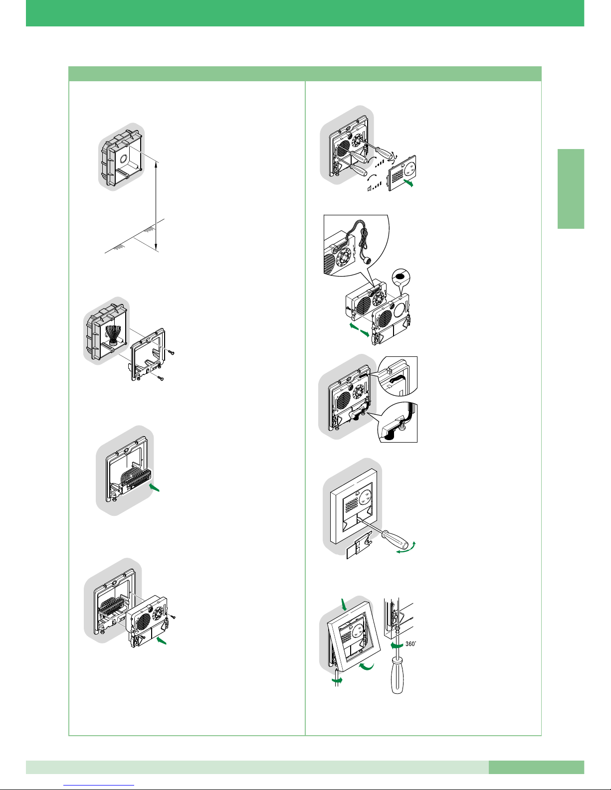
MT KIT 04
27
MT KIT 04
E N G L I S H
• Wall-mount the box 160÷165
cm from the finished floor,
in an area where it is easy
to see the visitor.
Possibly not towards
the sun or other direct light
sources (lamps, reflective
surfaces, etc.)
• Fix the frame on the flushmounting box using the 2
screws supplied.
• Insert the terminal block and
connect the wires according to
the diagram.
• Fit the snap-on module onto
the terminal and fix it with the 2
screws provided.
160 - 165 cm
Carla
Rossi
+
-
+
-
Carla
Rossi
OPEN
1
2
3
CLOSE
+
-
+
-
MIC
4
5
2
3
1
• Remove the stainless steel front
to carry out volume adjustments
and adjust the camera.
NOTE: Loosen the four screws
slightly to unlock the camera
and allow adjustment.
• Alternative microphone position.
• To remove name tag holder,
insert the tip of the screwdriver
in the middle opening and
extract it.
• After adjusting, fix the trim by
means of the 2 bottom screws.
NOTE: To remove the trim,
undo the 2 bottom screws,
turning max. 360°.
Installation instructions Art. 4875/BK, 4876/BK
Page 30
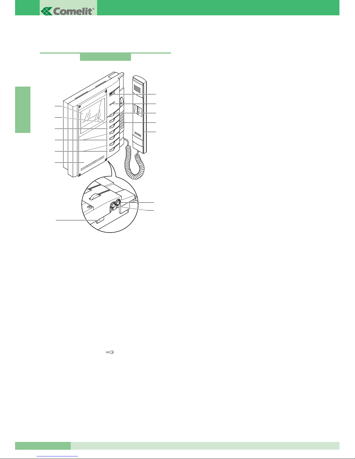
GROUP S.P.A.
MT KIT 04
28
E N G L I S H
INTERNAL UNITS
Technical characteristics of B/W Monitor Art. 5701
Bravo series wall-mounting monitor 212x225x55 mm, RAL9003
white (with front panel customisable according to user preferences
with customisation kit Art. 5727) and 4’’ B/W screen.
The Monitor can also be installed on a desktop by means of special
support Art. 5712.
1. Call volume adjustment / Privacy function selector (Privacy
service means exclusion of the call from the external unit and
from intercommunicating telephones or video doorphones;
Activation of the Privacy function is signalled by a red indicator
appearing at the left of the selector).
The user can select the preferr ed Monitor ringtone as
described on page 42.
2. Signalling LED (activation according to configuration adopted).
3. Door lock release pushbutton .
4. Pushbutton memo label for indicating pushbutton functions.
5. Monitor Handset (lift handset to start communication).
6. 4’’ B/W screen.
7. Standard front panel customisable with customisation Kit.
8. Pushbutton available standard, usable for various purposes
(C.NO. contact 1A max.) according to system needs; removing
CV3 and CV4 as given in the variant BK/P on page 89.
9. Pushbutton available standard.
10. Optional pushbuttons (using card Art. 5733 or Art. 5734) for
activating additional functions.
11. Optional pushbuttons (using card Art. 5733) or optional
signalling LEDs (using card Art. 5734) available for different
functions as given on page 40.
12 Brightness control
(turn clockwise to increase brightness).
13. Colour intensity control
(turn clockwise to increase the value).
14. Hooking bracket.
Up to a max. of 3 Monitors can be used in the same residence unit.
Art. 5701
6
1
2
3
4
5
6
8
4
5
3
2
1
9
10
11
7
12
13
14
Page 31
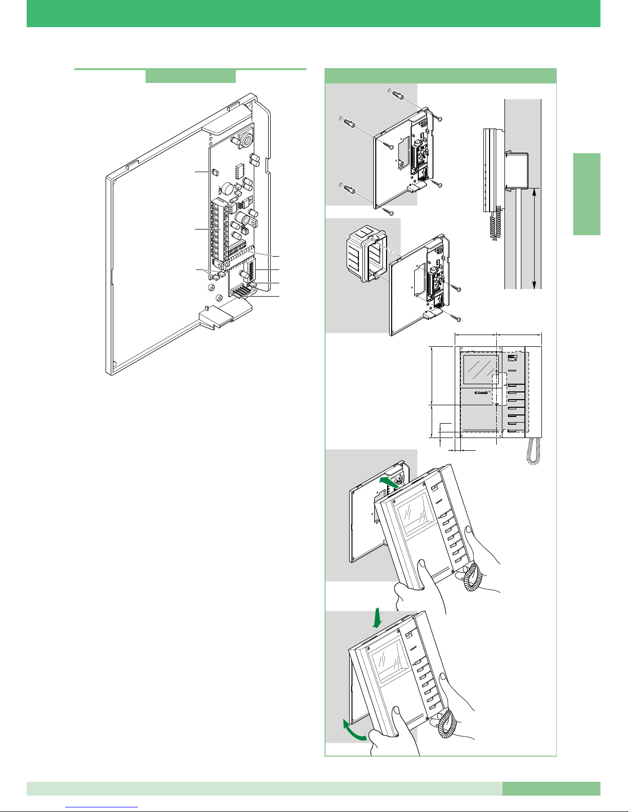
MT KIT 04
29
MT KIT 04
E N G L I S H
Monitor fixing bracket
The fixing bracket Art. 5714/K allows installation of the Monitor on
the wall or by means of the desk conversion support Art. 5712 (for
further information see page 28).
Technical characteristics
Dimensions: 170 x 200 x 28 mm.
1. Monitor Bracket Connector.
2. System connection terminals:
0 +20 Terminals for connection with Art. 1205/B or Art. 1212/B.
L L Connection terminals Bus line.
CFP CFP Local Floor call.
P1 C1 Pushbutton for various uses. To have an C.NO. clean
contact, remove jumper CV3 and CV4 (max 24V - 100mA).
S+ S- Terminals for call repetition device.
LED1 Input for management of signalling LED illumination
(in the presence of a signal on this terminal the LED
flashes; see variant BK/N on page 89).
3. Programming DIP switches.
4. Jumper CV5 for closing the Video signal.
5. Jumper CV3 and CV4 (to be removed to have an C.NO. clean
contact sui terminals P1C1).
6. Connector for connection of the optional supplementary card
Art. 5733 or Art. 5734.
7. Jumper JP1. Used to set the Monitor bracket as Main or
Secondary (see page 39).
1 2 3
4
ON
5 6 7
8
DIP
4
2
1
5
6
7
3
Art. 5714/K
1
2
3
4
5
6
cm 10,2 cm 11
cm 14,4
cm 8,1
145 cm
CV2
CV7
CV1
CV6
CV5
CV3
CV4
1
2
3
4
5
6
CV2
CV7
CV1
CV6
CV5
CV3
CV4
1
2
3
4
5
6
1
2
cm 1,4
cm 1,4
12 3
4
ON
56 7
8
DIP
12 3
4
ON
56 7
8
DIP
Installation of monitor Art. 5701 wall mounting
Page 32
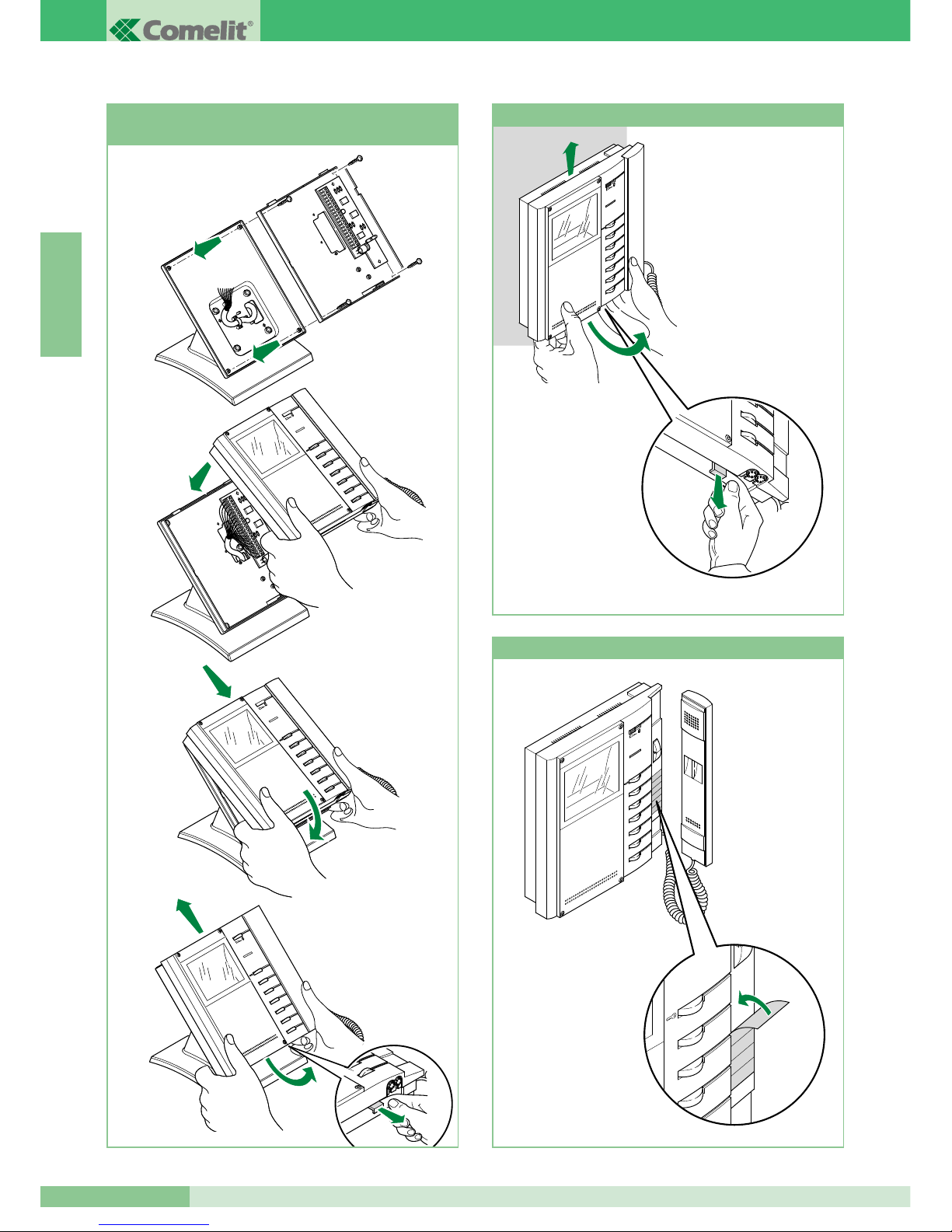
GROUP S.P.A.
MT KIT 04
30
E N G L I S H
1
2
3
4
5
6
1
1
2
3
4
5
6
2
3
6
5
4
3
2
1
6
5
4
Mounting Monitor Art. 5701 on desk
base Art. 5712
1
2
3
4
5
6
3
2
1
Procedure for removing the Monitor
1
2
3
4
5
6
1
2
Positioning of label on monitor
Page 33
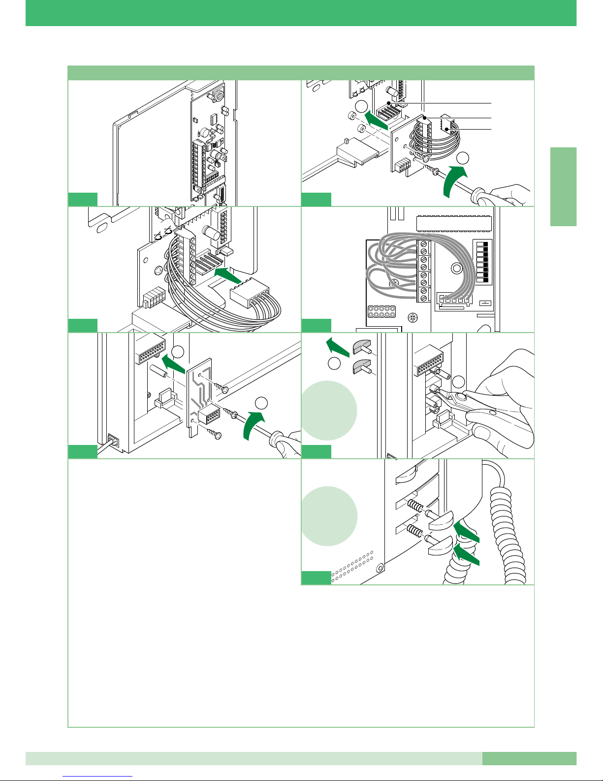
MT KIT 04
MT KIT 04
31
E N G L I S H
1 2 3
4
ON
5 6 7
8
DIP
CV3
1 2 3 4
ON
5 6 7
DIP
CV4
1
2
1
2
3
1
4
5734
5734 !
2
1
6
3
4
5
6
5734 !
7
1 Remove the bracket and the optional card from its pack.
2 Screw the optional card onto the plastic support of the bracket
using the screws provided.
1. Terminal board:
P3: Pushbutton 3 Contact of the Monitor. *
C3: Pushbutton 3 Common contact of the Monitor *.
Common main from bracket Art. 5714/K (disconnect the wire
towards the connector bracket to free all the common
contacts).
P4: Pushbutton 4 Contact of the Monitor. *
C4: Pushbutton 4 Common contact of the Monitor. *
+P5: Pushbutton 5 Contact of the Monitor for Art. 5733 *.
LED 5 positive input for Art. 5734.
-C5: Pushbutton 5 Common contact of the Monitor for
Art. 5733 *. LED 5 negative input for Art. 5734.
+P6: Pushbutton 6 Contact of the Monitor for Art. 5733 *.
LED 6 positive input for Art. 5734.
-C6: Pushbutton 6 Common contact of the Monitor for
Art. 5733 *. LED 6 negative input for Art 5734.
2. Male bracket connector.
3. Female connector Art. 5733 or Art. 5734.
3 Connect the female connector of the optional card to the male
connector located on the bracket.
4 Position the wires between the optional card and the bracket as
shown in the diagram.
5 Fix the optional card with connector onto the rear of the Monitor
using the screws provided.
6 Only for optional card Art. 5734: cut and remove Pushbuttons 5
and 6 of the Monitor.
7 Only for optional card Art. 5734: insert the transparent
Pushbuttons enclosed in the pack of the article in the positions
of Pushbuttons 5 and 6 as shown in the Figures.
*
To use the Pushbutton as C.NO. contact (24V-100mA max), remove the
wire towards the bracket connector and disconnect the relative common.
CV3
1
2
3 4
ON
5
6
7 8
DIP
CV4
3
1
2
5
Installation of optional card Art. 5733, Art. 5734
2
Page 34
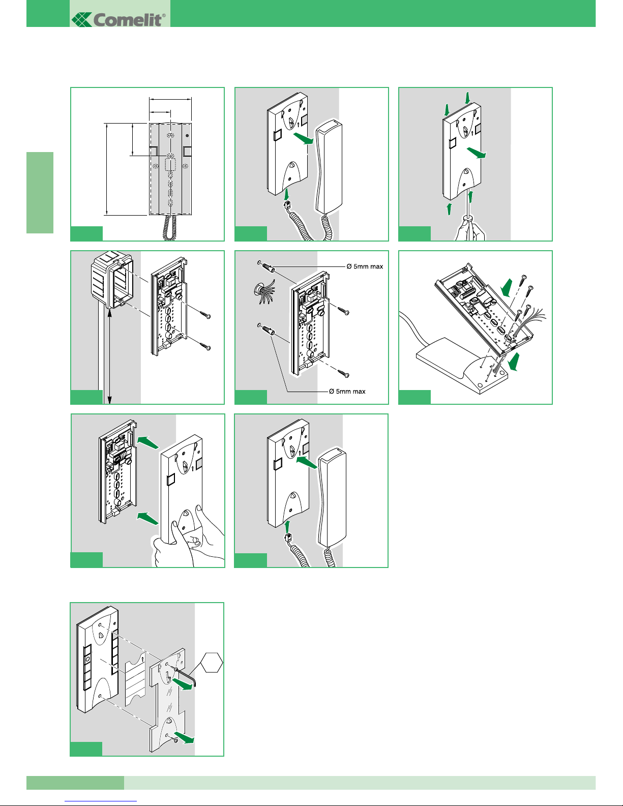
GROUP S.P.A.
MT KIT 04
32
E N G L I S H
Style telephone Art. 2608, 2628 and 2610 installation instructions
Interchangeable cover available for Art. 2628 and Art. 2610
1
2
145 cm
4A 4B
95mm
47,5mm
75,5mm
215mm
1
1
1
1
1
2
3
1
4
2
2
5
6
2
4
6
1
3
5
7
9
2
8
CH2
7
1
2
4C
Page 35
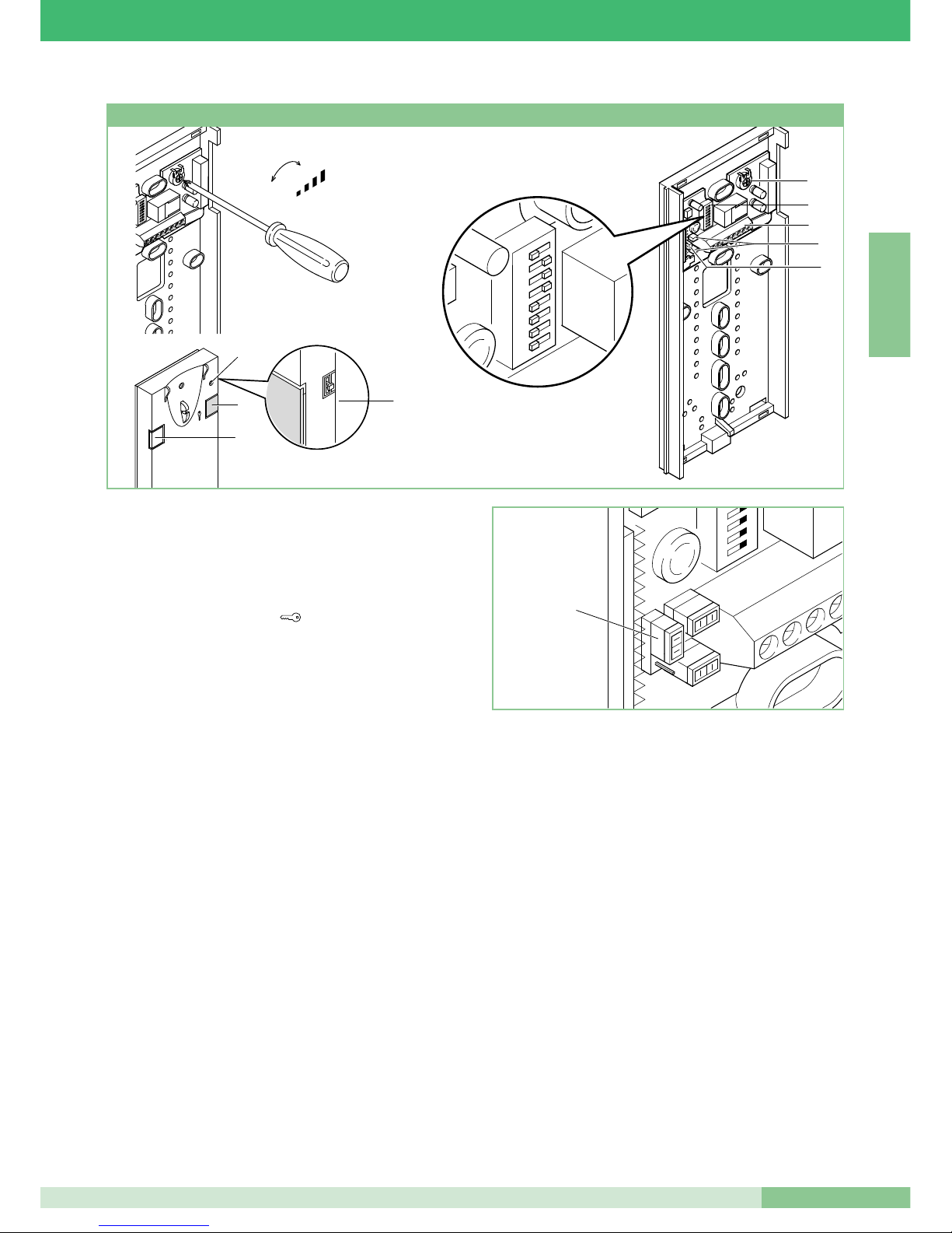
MT KIT 04
33
MT KIT 04
E N G L I S H
+
-
MIC
1 2 3 4 5 6 7 8
c
A
3
9
8
5
7
6
JP1
4
1
2
Basic telephone with 2 pushbuttons standard.
Cannot be used for the intercom function.
The Telephone must always be mounted using Art. 1214/2 as
shown in the BK/D connection diagram on page 85.
1. Door lock release pushbutton .
2. Pushbutton P1 switchboard call / generic actuator / pushbutton
for various uses present on terminal block (P1 C1).
3. 3-position ringtone/Privacy service selector:
High position: Max. ringtone volume.
Middle position: Medium ringtone volume.
Low position: Privacy function activation
(Privacy service means exclusion of the call ringtone from the
external unit and switchboard; activation of the function is
signalled by a red indicator appearing at the top right).
4. Privacy function indicator.
5. System connection terminals:
L L bus line connection.
CFP CFP floor door call input.
P1 C1 terminals for pushbutton P1 C. NO. 24V 100mA
dedicated to various services (remove CV1 and CV2).
S+ S- terminals for call repetition device.
6. JP1 jumper for selecting switchboard call (position C) / Generic
actuator (position A) function of pushbutton P1 (see figure
opposite).
7. CV1 CV2 jumper to be removed in order to have C. NO.
voltage-free contact on pushbutton P1.
8. Dip switches for setting user code (see table on page 39).
9. Microphone volume control trimmer.
Clean using a cloth moistened with water. Do not use alcohol
and other aggressive products.
Style telephone Art. 2608
Page 36
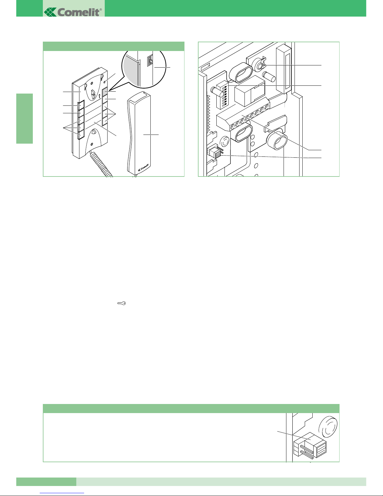
GROUP S.P.A.
MT KIT 04
34
E N G L I S H
Eleg ance t elep hone w ith a ddit iona l func tion s and
pushbuttons.
Cannot be used for the intercom function.
The Telephone must always be installed using Art. 1214/2 as
shown in the BK/D connection diagram on page 85.
Important: For correct setting of the Article during installation
inside a BRAVO KIT system, refer to the note below.
1. 3-position ringtone/Privacy service selector:
High position: Max. ringtone volume.
Middle position: Medium ringtone volume.
Low position: Privacy function activation
(Privacy service means exclusion of the call from the external unit
or the switchboard; activation of the Privacy function is signalled by
a red indicator appearing at the top right).
2. Privacy function indicator.
3. Pushbutton 1 available standard for generic actuator function.
4. Door lock release pushbutton .
5. Pushbutton 2 available standard for switchboard call function.
6. Pushbutton 3 for various uses present on terminal block (P3 C3).
7. Optional pushbuttons C. NO. or LEDs (MAX 3) for additional
functions. (A)
8. Replaceable cover Fig. 7 page 32.
9. Pushbut t o n memo label for indicating the telephone
pushbutton functions (to be applied under the interchangeable
cover) Fig. 7 page 32.
10. Telephone handset (lift the handset to start communication).
(A) Pushbutton available with optional card Art. 1626.
Display LED available with optional card Art. 1627.
11. System connection terminals:
L L bus line connection.
CFP CFP floor door call input.
P3 C3 terminals for pushbutton P3 C. NO. 24V 100mA
dedicated to various services.
S+ S- terminals for call repetition device.
12. JP1 Jumper for selection of Simplebus 1 and Simplebus 2
mode.
13. Dip switches U2 for setting user code (see table on page 39).
14. Microphone volume control trimmer.
Clean using a cloth moistened with water. Do not use alcohol
and other aggressive products.
ATTENTION !
TO USE TELEPHONE ART. 2628 IN BRAVO KIT SYSTEMS, JUMPER JP1 MUST BE SHIFTED TO
POSITION S1
S1
1
3
2
5
4
7
6
9
8
Style telephone Art. 2628
JP1
14
13
11
12
8
3
6
7
9
7
5
4
2
1
10
8
3
6
7
9
7
5
4
2
1
10
Page 37
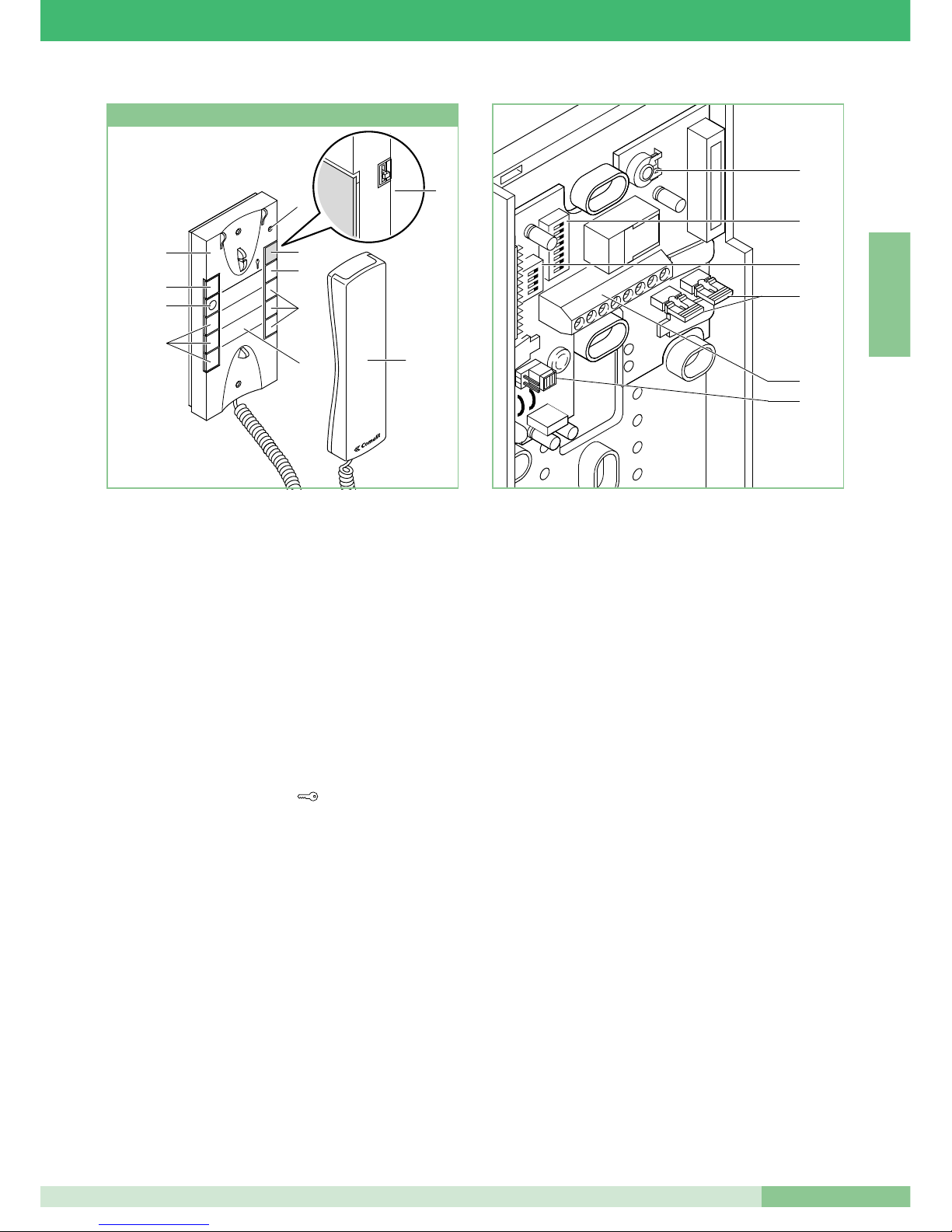
MT KIT 04
35
MT KIT 04
E N G L I S H
1
3
2
5
4
7 6
9
8
11. System connection terminals:
L L bus line connection.
CFP CFP floor door call input.
P2 C2 pushbutton P2 C terminals. NO. 24V 100mA dedicated
to various services (remove CV2 and CV3).
S+ S- Terminals for call repetition device.
12. JP1 Jumper for selection of Simplebus 1 and Simplebus 2
mode.
13. CV3 CV2 Jumper to be removed in order to have pushbutton
P2 C. NO.
14. Dip switches U2 for setting user code (see table on page 39).
15. Dip switches U4 for programming pushbuttons P1 and P2 (see
table on page 43).
16. Microphone volume control trimmer.
Clean using a cloth moistened with water. Do not use alcohol
and other aggressive products.
Style telephone Art. 2610
16
14
15
13
11
12
8
3
6
7
9
7
5
4
2
1
10
Elegan ce t elepho ne w ith add i tiona l fu n ction s an d
pushbuttons and intercom service.
By means of special setting, Art. 2610 can manage intercom calls
and other additional functions (see summary table on page 40).
The Telephone must always be mounted using Art. 1214/2 as
shown in the BK/D connection diagram on page 85.
1. 3-position ringtone/Privacy service selector:
High position: Max. ringtone volume.
Middle position: Medium ringtone volume.
Low position: Privacy function activation.
(Privacy service means exclusion of the call from the external
unit and switchboard; activation of the Privacy function is
signalled by a red indicator appearing at the top right).
2. Privacy function indicator.
3. Signalling LED (available standard).
4. Door lock release pushbutton .
5. Pushbutton 1 available standard (programmable with
various functions, see table on page 43. Factory-set for
generic Actuator function).
6. Pushbutton 2 available standard (freeable, or programmable
with various functions, see table on page 43).
Factory-set for switchboard call function.
7. Op tio nal pus h but ton s C. NO . or LED s (M AX 3) fo r
additional functions. (A)
8. Interchangeable cover Fig. 7 on page 32.
9. Pushbutton memo label fo r indicating th e telephone
pushbutton functions (to be applied under the interchangeable
cover) Fig. 7 on page 32.
10. Telephone handset (lift the handset to start communication).
(A) Pushbutton available with optional card Art. 1626.
Display LED available with optional card Art. 1627.
Page 38
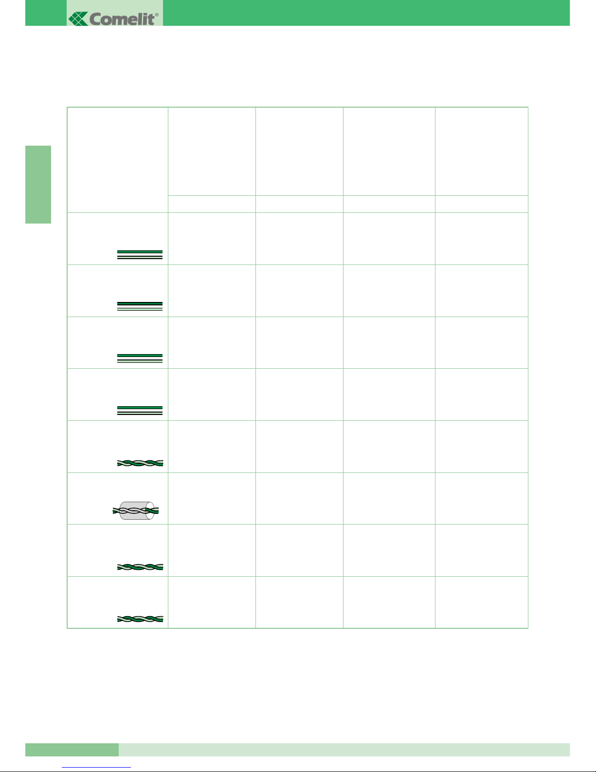
GROUP S.P.A.
MT KIT 04
36
E N G L I S H
Maximum distance
between external unit
4875/BK or 4876/BK
and the furthest 4833/A
or 1214/2. Maximum
distance between 4833/A
and the furthest 1214/2
Maximum distance
between monitor
and 1214/2
This section of the manual gives all the information concerning the BRAVO KIT system installation stage.
The maximum total distance between the external unit and the furthest monitor is 400 m.
GENERAL INSTALLATION AND OPERATION INSTRUCTIONS
Cable section or type Maximum distance
between
power supply 1205/B
or 1395 and external unit
4875/BK and 4876/BK
Maximum distance
between power supply
1205/B or 1212/B
and powered monitor
A/G B/E C/F D
Double-wire cable
(section 0.5 mm
2
Ø 0.8 mm AWG 20)**
Double-wire cable
(section 1 mm
2
Ø 1.2 mm AWG 17)**
Double-wire cable
(section 1.5 mm
2
Ø 1.4 mm AWG 15)**
Double-wire cable
(section 2.5 mm
2
Ø 1.8 mm AWG 13)**
Twisted telephone pair
(section 0.28 mm
2
Ø 0.6 mm AWG 23)*
Braided and screened cable
(section 1 mm2Ø 1.2 mm
AWG 17)*
UTP5 Cat. 5
(section 0.2 mm
2
Ø 0.5 mm AWG 24)*
Comelit cable Art. 4576
and Art. 4578
(section 0.5 mm2Ø 0.8 mm
AWG 20)*
* In case of multipair cable, it is advisable to use only one of the pairs for the system.
To reduce resistive drops, use a single pair as a single wire.
** In case of multicore cable, use only two of the available wires and never use wires in parallel.
20 m
(65 feet)
40 m
(130 feet)
60 m
(195 feet)
100 m
(325 feet)
25 m
(85 feet)
50 m)
(165 feet)
100 m
(325 feet)
150 m
(495 feet)
150 m
(495 feet)
150 m
(495 feet)
150 m
(495 feet)
150 m
(495 feet)
100 m
(325 feet)
150 m
(495 feet)
150 m
(495 feet)
40 m
(130 feet)
40 m
(130 feet)
40 m
(130 feet)
40 m
(130 feet)
20 m
(65 feet)
40 m
(130 feet)
50 m
(165 feet)
Page 39
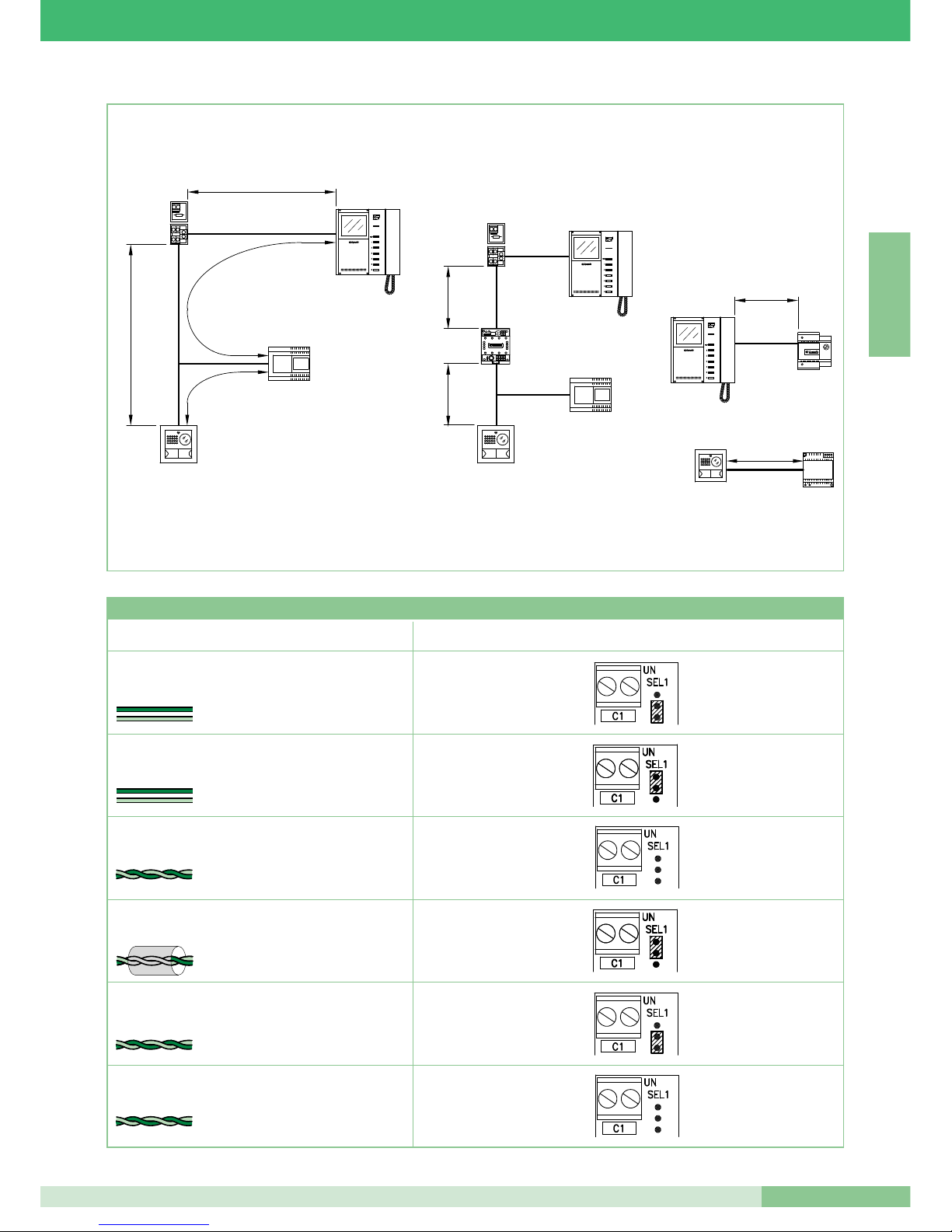
MT KIT 04
37
MT KIT 04
E N G L I S H
4875/BK
4876/BK
1205/B
1214/2
1216
C
A
B
D
4875/BK
4876/BK
1214/2
1216
F
F
4833/A
1212/B
E
1205/B
1395
4875/BK
4876/BK
G
Type of cable Setting Art. 1216
Double-wire cable (section 1.5 mm2 Ø 1.4 mm AWG 15)
Double-wire cable (section 1 mm2 Ø 1.2 mm AWG 17)
Twisted telephone pair
(section 0.28 mm2 Ø 0.6 mm AWG 23)
UTP5 cable cat. 5
(section 0.2 mm2 Ø 0.5 mm AWG 24)
2
1
Comelit cable Art. 4576 and Art. 4578 (section 0.5 mm
2
Ø 0.8 mm AWG 20)
Double-wire cable
(section 0.5 mm2Ø 0.8 mm AWG 20)
2
Braided and screened cable
(section 1 mm2 Ø 1.2 mm AWG 17)
1
Table of Settings Art. 1216 according to the type of connection cable used
Page 40
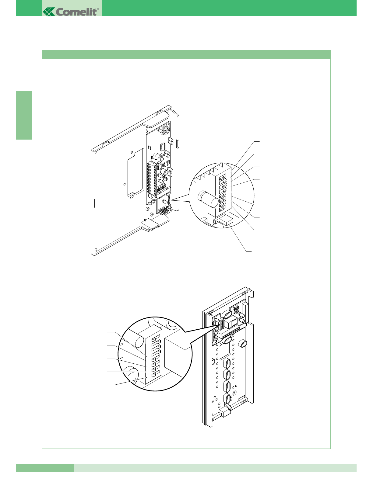
MT KIT 04
38
GROUP S.P.A.
E N G L I S H
1 2 3
4
ON
5 6 7
8
DIP
1 2 3
4
ON
5 6 7
8
DIP
S1-8
S1-7
S1-6
S1-4
S1-3
S1-2
S1-1
S1-5
JP1
Settings for bracket 5714/K and telephones Style Art. 2608, 2628 and 2610
BRAVO KIT SYSTEM SETTINGS AND OPERATION DESCRIPTION
The Figure below shows the position of the DIP switches and of Jumper JP1 of bracket 5714/K and of the DIP switches of telephones
Style Art. 2608, 2628 and 2610.
1 2 3 4 5 6 7 8
S1-5
S1-4
S1-3
S1-2
S1-1
Page 41
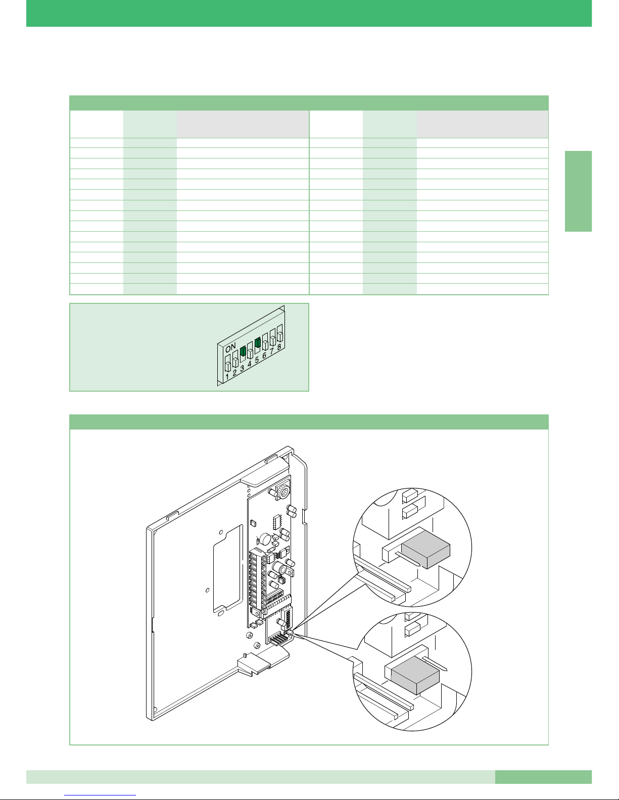
39
MT KIT 04
MT KIT 04
E N G L I S H
The values of S1-1, S1-2, S1-3, S1-4 and S1-5 define the call address.
Refer to the following table for the coding of brackets and telephones.
WARNING: ON TELEPHONES 2608, 2628 AND 2610 SET
POSITION TO OFF I DIP 6, 7, 8
The two-residence intercom call (between telephones and/or video
doorphones) is possible only if the two users are set to contiguous
call codes (marked with the same letter AA…CC..YY in the
Microswitch programming table given above).
Table of user code programming microswitches on Brackets and telephones
EXAMPLE setting code 20.
H 16 5
I 17 1,5
I 18 2,5
J 19 1,2,5
J 20 3,5
K 21 1,3,5
K 22 2,3,5
L 23 1,2,3,5
L 24 4,5
M 25 1,4,5
M 26 2,4,5
N 27 1,2,4,5
N 28 3,4,5
O 29 1,3,4,5
O 30 2,3,4,5
A 1 1
A 2 2
B 3 1,2
B 4 3
C 5 1,3
C 6 2,3
D 7 1,2,3
D 8 4
E 9 1,4
E 10 2,4
F 11 1,2,4
F 12 3,4
G 13 1,3,4
G 14 2,3,4
H 15 1,2,3,4
Reference for
intercom User code Microswitches ON
two-residence
Reference for
intercom User code Microswitches ON
two-residence
1 2 3
4
ON
5 6 7
8
DIP
1 2
ON
1
ON
Setting bracket Art. 5714/K main or secondary
Main
Secondary
Page 42
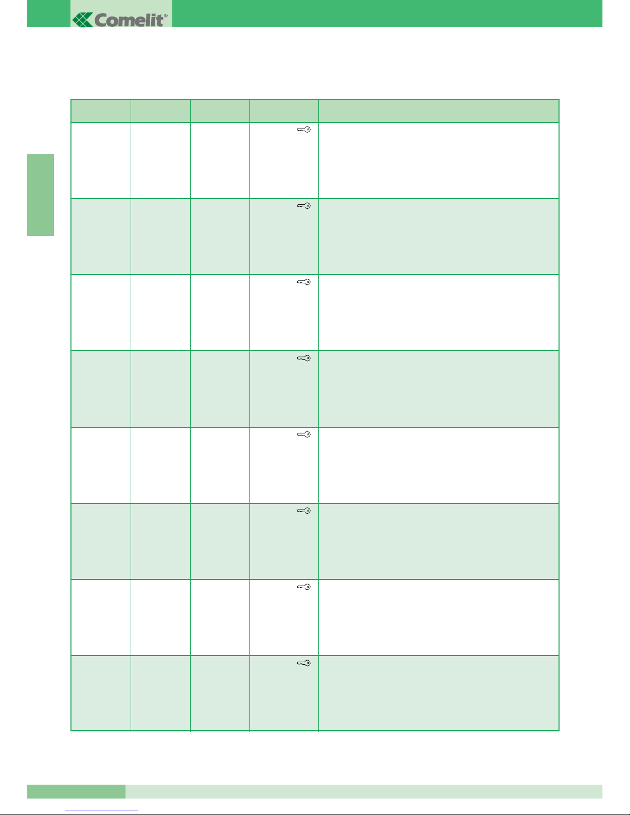
GROUP S.P.A.
MT KIT 04
40
E N G L I S H
OFF
(0)
OFF
(0)
OFF
(0)
S1-6 S1-7 S1-8 Button functions
Pushbutton
Pushbutton 1
Pushbutton 2
Pushbutton 3
Pushbutton 4
Pushbutton 5
Pushbutton 6
Door lock release
Actuator / Free Pushbutton
Video Request / Internal switch-on
Switchboard call
Single-residence intercom call
Two-residence intercom call
(1)
Doctor function management
ON
(1)
OFF
(0)
OFF
(0)
Pushbutton
Pushbutton 1
Pushbutton 2
Pushbutton 3
Pushbutton 4
Pushbutton 5
Pushbutton 6
Door lock release
Single-residence intercom call
Two-residence intercom call
Switchboard call
Single-residence intercom call
Two-residence intercom call
(1)
Doctor function management
OFF
(0)
ON
(1)
OFF
(0)
Pushbutton
Pushbutton 1
Pushbutton 2
Pushbutton 3
Pushbutton 4
Pushbutton 5
Pushbutton 6
Door lock release
Single-residence intercom call
Doctor function management
Switchboard call
Single-residence intercom call
Two-residence intercom call
(1)
Doctor function management
ON
(1)
ON
(1)
OFF
(0)
Pushbutton
Pushbutton 1
Pushbutton 2
Pushbutton 3
Pushbutton 4
Pushbutton 5
Pushbutton 6
Door lock release
Two-residence intercom call
Doctor function management
Switchboard call
Single-residence intercom call
Two-residence intercom call
(1)
Doctor function management
OFF
(0)
OFF
(0)
ON
(1)
Pushbutton
Pushbutton 1
Pushbutton 2
Pushbutton 3
Pushbutton 4
Pushbutton 5
Pushbutton 6
Door lock release
Single-residence intercom call
Video Request / Internal switch-on
Switchboard call
Single-residence intercom call
Two-residence intercom call
(1)
Doctor function management
ON
(1)
OFF
(0)
ON
(1)
Pushbutton
Pushbutton 1
Pushbutton 2
Pushbutton 3
Pushbutton 4
Pushbutton 5
Pushbutton 6
Door lock release
Two-residence intercom call
Video Request / Internal switch-on
Switchboard call
Single-residence intercom call
Two-residence intercom call
(1)
Doctor function management
OFF
(0)
ON
(1)
ON
(1)
Pushbutton
Pushbutton 1
Pushbutton 2
Pushbutton 3
Pushbutton 4
Pushbutton 5
Pushbutton 6
Door lock release
Switchboard call
Video Request / Internal switch-on
Switchboard call
Single-residence intercom call
Two-residence intercom call
(1)
Doctor function management
ON
(1)
ON
(1)
ON
(1)
Pushbutton
Pushbutton 1
Pushbutton 2
Pushbutton 3
Pushbutton 4
Pushbutton 5
Pushbutton 6
Door lock release
Switchboard call
Actuator control
Switchboard call
Single-residence intercom call
Two-residence intercom call
(1)
Doctor function management
The value of S1-6, S1-7 and S1-8 (only for bracket Art. 5714/K) defines the mode in which the Bravo KIT System will operate as given in the
following table.
(1)
The two-residence intercom call (between telephones and/or video doorphones) is possible only if the two users are set to
contiguous call codes (marked with the same letter AA…CC..YY in the Microswitch programming table given on page 39).
Page 43

MT KIT 04
41
MT KIT 04
E N G L I S H
MICROSWITCHES S1-1, S1-2, S1-3, S1-4 AND S1-5
The values of the microswitches S1-1, S1-2, S1-3, S1-4 and S1-5
define the call address of the bracket in question with respect to the
external call unit.
To use the tw o - r e s i dence intercom call fu n c tion the
users(telephones and/or video doorphones) must be set to
contiguous call addresses m arked with the same letter
(AA…CC….YY) in the table on page 39.
Operation
• By pressing the call button the visitor activates the infrared LEDs
for illuminating the person, the internal call ringtone (if the
Privacy function is not enabled) and displays the image on the
main monitor/s for approx. 60 seconds.
On answering the communication, the maximum duration of the
conversation is 90 seconds.
A call confirmation tone sounds at the external unit; in systems
with 2 or more entrances, if the external unit emits an engaged
tone instead of t he ringtone this m e a n s that another
communication is already in progress with another external unit.
In case of a persistent short-circuit on the bus line, the
external unit emits an intermittent signalling tone.
• Communication occurs at the internal unit by lifting the handset.
• The brightness control is located on the lower part of the Monitor,
whereas the ringtone volume or Privacy function activation
control is at the top.
• The button marked with the key symbol on the Monitor acts on
the electric lock, activating it for approx. 2 seconds.
• Automatic switch-on of the main Monitor occurs by pressing
Pushbutton 2 with function enabled (see description on page 43).
In systems with 2 external units, it is possible to view the image
from one external unit or the other alternately (“toggle” function)
by pressing Pushbutton 2.
Automatic Monitor switch-on is not possible during another
conversation.
• For the intercom functions of the BRAVO KIT System, refer to
page 40.
• For programming user addresses different from the factorysettings (1 and 2) refer to page 45.
Main or secondary additional monitors
The setting of JP1 defines whether the bracket in question will be
managed as main or secondary. The external unit can manage up
to a maximum of 3 Video doorphones or Telephones for each Call
button. When a call is made from the external unit, the monitor
switched on b y the system w i ll be that o f the main Video
doorphone.
Any other secondary monitors in the same residence unit will
remain off. By answering the external unit call from a secondary
Video doorphone, the image is automatically displayed on the
Monitor.
The monitor of the main Video doorphone will be switched off and
the image will be displayed on the monitor of the Video doorphone
on which Pushbutton 2 - video request was pressed.
The image transmitted from the external unit can be viewed even
without lifting the handset, simply by pressing Pushbutton 2 -
video request.
In the classic BRAVO KIT configuration, it is therefore possible to
have at most 2 secondary Video doorphones and 1 main Video
doorphone for each Call button, all powered by the same Art.
1205/B (Variant BK/C page 84).
Up to 3 main Video doorphones inside the same residence unit (i.e.
set to the same user code) can be managed. In this particular
configuration, the additional main Video doorphones must each be
powered by the special Art. 1212/B (Variant BK/H and BK/I page
83, 84).
At the call from the external unit, the image will be displayed on
each of the main Video doorphones connected to the system.
In any case, even when using Art. 1212/B, a max. of 3 Video
doorphones can be connected for the same residence unit. A
dedicated power supp ly is not necessary for any optional
Telephone.
S1-6, S1-7, S1-8
Setting BRAVO KIT operating mode
The table on page 40 shows the functions of the single Monitor
pushbuttons according to how the microswitches S1-6, S1-7, S1-8
are set.
Pushbutton , Pushbutton 1 and Pushbutton 2 are standard,
whereas Pushbutton 3, Pushbutton 4, Pus h b u t t o n 5 and
Pushbutton 6 are optionals using card Art. 5733.
Using Art. 5734 it is also possible to have the availability of
Pushbutton 3 and Pushbutton 4 and two signalling LEDs in the
positions of Pushbutton 5 and Pushbutton 6.
These signalling LEDs can be used by the installer for various
system needs and will not be managed in automatic mode by the
Monitor bracket.
Description of Pushbutton functions
Door lock release Pressing the Door lock release
Pushbutton activates the lock connected to the external unit.
Actuator Pressing the Pushbutton set in Actuator mode
enables activation of Art. 1256, which can be used to open
gates, up&over doors, etc., or to activate the cyclic camera
module Art. 1259/A.
Free Pushbutton The indication Free Pushbutton means that
the Pushbutton can be used as a C.NO. contact in the terminal
block, by means of suitable settings as illustrated in the BK/P
variant on page 89.
Video request / Automatic Switch-on Press Pushbutton 2 in
this mode to display the image on the Monitor transmitted by the
external unit, even if no call has been made.
For use and enabling of the service, see BK/P variant on page 89.
In systems equipped with two external units, it is possible to view
the image from one external unit or the other alternately (“toggle”
function) by pressing the Pushbutton.
Page 44
GROUP S.P.A.
MT KIT 04
42
E N G L I S H
On secondary Monitors, Pushbutton 2 also has the video request
function (for more information see page 43).
Switchboard call Press the Pushbutton set in this mode to
send a call to the system porter Switchboard.
Single-residence intercom call Press the Pushbutton set in
this mode to send a call to the other units (Video doorphones
and/or Telephones) set to the same call address.
By lifting the handset, the receiver of the call communicates with
the caller.
The communication is ended by hanging up the handset.
In any case, a call from the external unit always has priority over an
intercom call. In this case, users who are already speaking will hear
a tone similar to the ringtone in the handset if the latter is for them,
or otherwise a triple signal tone.
To answer the call from the external unit, simply lift the handset of
any free unit or hang up and lift the handset of a unit engaged in
the intercom call.
Activation of communication with the external unit interrupts the
intercom conversation previously in progress.
An intercom call does not have priority over a conversation/call with
the external unit.
In this case, during an intercom call attempt, the LED will flash for a
few seconds to signal that the system is engaged.
Two-residence intercom call Press the Pushbutton set in this
mode to send a call to the other units (Video doorphones and/or
Telephones) set to the two-residence call address, as indicated in
the table on page 39.
By lifting the handset, the receiver of the call communicates with
the caller. The communication is ended by hanging up the handset.
In any case, a call from the external unit always has priority over an
intercom call.
In this case, users who are already speaking will hear a tone
similar to the ringtone in the handset if the latter is for them, or
otherwise a triple signal tone.
To answer the call from the external unit, simply lift the handset of
any free unit or hang up and lift the handset of a unit engaged in
the intercom call.
Activation of communication with the external unit interrupts the
intercom conversation previously in progress.
An intercom call does not have priority over a conversation/call with
the external unit.
In this case, during an intercom call attempt, the LED will flash for a
few seconds to signal that the system is engaged.
Doctor function management The Doctor function enables
automatic activation of the door lock release with call to the
address of the Video doorphone and/or Telephone where the
function was activated, by the external unit.
With the function activated, the signalling LED stays on. The Doctor
function is enabled or disabled by pressing the pushbutton set for
that function for 2 seconds.
Monitor ringtone selection procedure
The user can select the Monitor ringtone from a list of available
ringtones, carrying out the following procedure:
(1) Keep the Pushbutton pressed until a confirmation tone
sounds (this operation is only possible with the system in
standby mode; otherwise the signalling LED will flash to warn
the user).
(2) Press and release the Pushbutton :
once (a confirmation tone sounds) to change the call ringtone
from external unit.
twice (2 confirmation tones sound) to change the ringtone from
switchboard.
three times (3 confirmation tones sound) to change the door
bell ringtone.
Further pressing of the Pushbutton repeats the sequence
described above.
After the last time the Pushbutton is pressed, wait for a
confirmation tone before going to the next stage.
(3) Press and release the Pushbutton to scroll the various
available ringtones in sequence. To hear the same ringtone
again, keep the Pushbutton pressed.
(4) Lift and then hang up the handset to confirm selection of the
last ringtone heard and to exit (at any time) the Monitor
ringtone change mode. On exiting Monitor ringtone change
mode a confirmation tone will sound. The Video doorphone
now resumes its normal operation.
Page 45
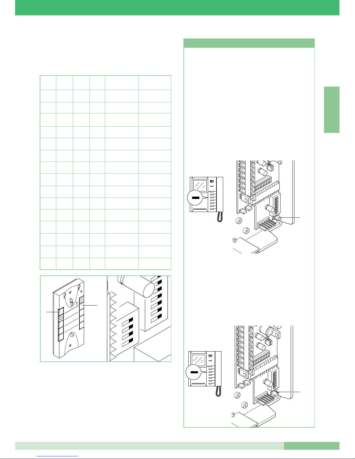
MT KIT 04
43
MT KIT 04
E N G L I S H
Setting telephone (optional) Art. 2610
To extend the BRAVO KIT system by adding the optional
Telephone Art. 2610, the table necessary for defining the
required Telephone functions is given below.
DIP 1 DIP 2 DIP3 DIP 4 Button 1 function Button 2 function
0 0 0 0
Generic actuator Switchboard call
1
0 0 0
Switchboard call
Single-residence
Inter.
0
1
0 0
Switchboard call Two-residence Inter.
1 1
0 0
Generic actuator
Single-residence
Inter.
0 0
1
0
Generic actuator Two-residence Inter.
1
0
1
0
Doctor Switchboard call
0
1 1
0
Doctor Generic actuator
1 1 1
0
Doctor
Single-residence
Inter.
0 0 0
1 Doctor Two-residence Inter.
1
0 0
1
Single-residence
Inter.
Two-residence Inter.
0
1
0
1 Switchboard call Automatic switch-on
1 1
0
1 Actuator Automatic switch-on
0 0
1 1 Doctor Automatic switch-on
1
0
1 1
Single-residence
Inter.
Automatic switch-on
0
1 1 1 Two-residence Inter. Automatic switch-on
2
ON
U4
4
3
1
1
3
2
5
4
7
6
9
8
P1
P2
Self Ignition Function (only for systems with 1 or 2 inputs) on
monitor with brackets Art. 5714/K set as Main (see JP1 in the
Figure, in position P).
The Self Ignition function must be enabled.
Enabling/disabling the Self Ignition function: to enable the
function it is necessary to keep pushbutton 2 of the monitor
pressed (pay attention to the BRAVO KIT mode set by means of
the programming DIP switches) for a time of more than 4 sec.
When setting has taken place, by putting the receiver to your
ear, a double confirmation tone is heard.
To disable it, keep the same pushbutton pressed for a time of
more than 4 sec. In this case, by putting the receiver to your
ear, a single confirmation tone is heard.
Use of self-ignition: the monitor lights up (if the function has
been enabled) by pressing and immediately releasing
Pushbutton 2.
Video Request on monitor with brackets Art. 5714/K set as
Secondary (see JP1 in the Figure, in position S).
The Video request function does not require enabling.
It allows a monitor to be turned on following a call from the
external unit for the user.
Use of the Video request function: the monitor lights up by
pressing and immediately releasing Pushbutton 2 (pay
attention to the BRAVO KIT mode set by means of the
programming DIP switches).
1 2 3
4
ON
5 6 7
8
DIP
JP1
1
2
3
4
5
6
2
Self Ignition and Video Request Function
1 2 3
4
ON
5 6 7
8
DIP
JP1
1
2
3
4
5
6
2
Page 46
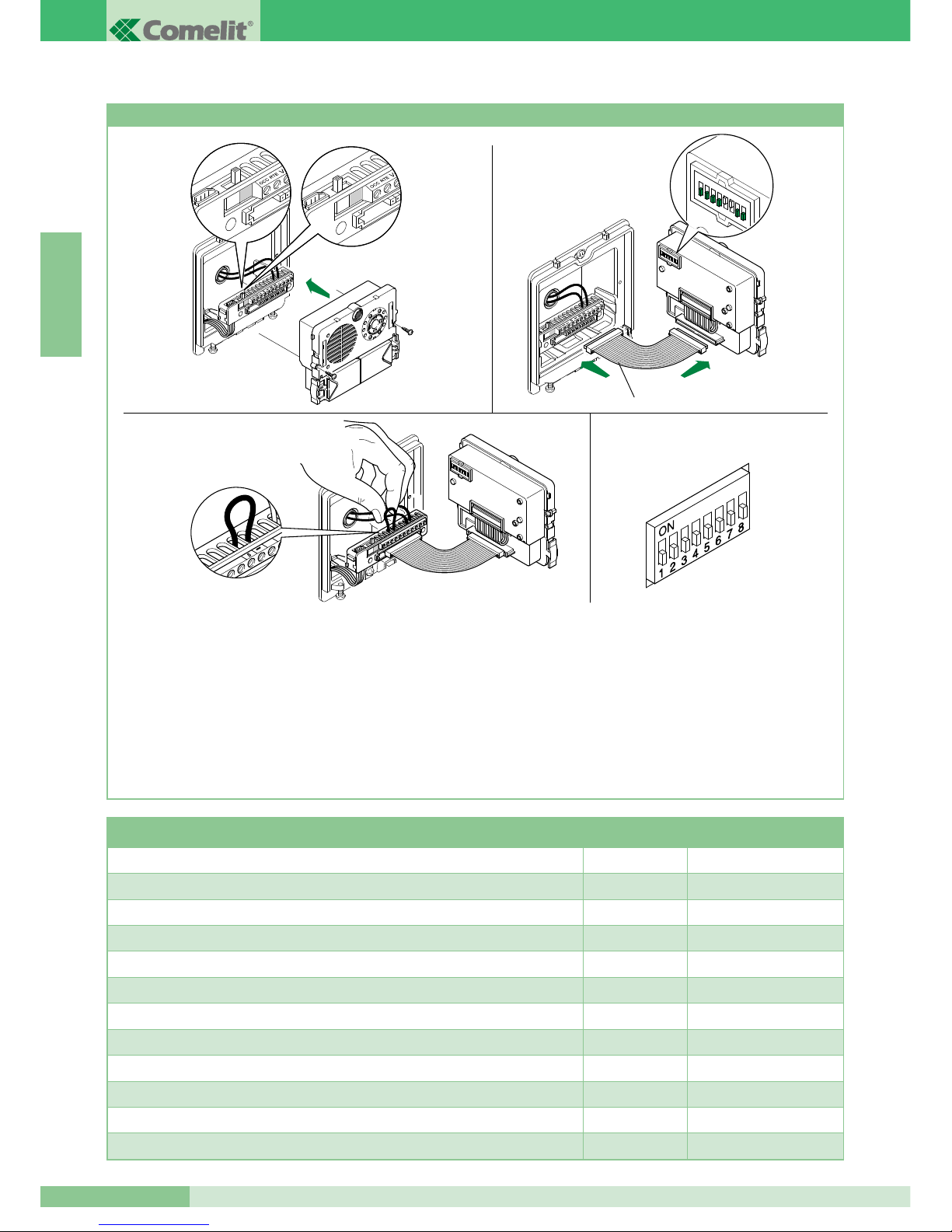
GROUP S.P.A.
MT KIT 04
44
E N G L I S H
Special programming Art. 4660/BK
A number of special programming operations can be carried out on
Art. 4660/BK according to the various system requirements.
1. On the terminal block of articles 4660/BK, set the switch to
programming (red) (Figure 1A).
2. On the microswitches of the article (Figure 2), set the code for
the function to be programmed. Use the following table as a
reference.
3. On the terminal block of articles 4660/BK, connect terminal
S with – (Figure 3).
4. Wait for a programming confirmation tone and remove the
jumper between terminal S and -.
5. At the end of the procedure, make sure to have set the switch to
standby (white) (Figure 2A), removed the jumpers between
terminals S and - and turn all the microswitches to OFF (0) as
shown in Figure 4.
To carry out another special programming, repeat the above
operations from point 1 to point 5.
1
2 3
4 5
6 7 8
ON
DIP
Art. 3309
Fig. 1A Fig. 2A
Fig. 1
Fig. 3
Fig. 2
Fig. 4
Dip switches ON
Configuration
reference number
10-second reset wait time (factory-setting) 1,2,5,6,7,8 243
1-second reset wait time 3,5,6,7,8 244
Deactivation of door lock confirmation tone and door lock time setting 2 seconds (factory-settings) 1,3,5,6,7,8 245
Activation of door lock confirmation tone 2,3,5,6,7,8 246
Door lock time 8 seconds 1,2,3,5,6,7,8 247
Sending single call (factory-setting) 4,5,6,7,8 248
Sending call repeated 3 times 1,4,5,6,7,8 249
Door lock release control normally open (NO) (factory-setting) 2,4,5,6,7,8 250
Door lock release control normally closed (NC) 1,2,4,5,6,7,8 251
Door lock release active even with no call (factory-setting) 3,4,5,6,7,8 252
Door lock release only enabled for the user called 1,3,4,5,6,7,8 253
Reset of all factory-settings 2,3,4,5,6,7,8 254
Page 47

MT KIT 04
45
MT KIT 04
E N G L I S H
BRAVO KIT SYSTEM EXPANDABILITY
following p r o c e d u re, and the br a c k e t s 5714/K with th e
corresponding code (see table on page 39).
For further information on integration of the BRAVO KITS in
Simplebus systems and for programming the main entrance
panel (Art. 4660), refer to the Simplebus 2 catalogue (Catalogue
no. 66), the MT/SB2/01 technical manual and the FT/SB/16
technical sheet.
The diagrams BK/EN/100 and BK/EN/101 on page 90, 92, in
section A of this manual, show a possible system configuration
for managing up to a max. of 30 BRAVO KITS with one Art. 4660
placed, for example, at the entrance of a residential complex.
With these system diagrams it is possible to call one of the
BRAVO KITS from the main entrance equipped with Art. 4660.
In this configuration it is necessary to programme the pushbuttons
of Art. 4660/BK on Art. 4875/BK or 4876/BK as described in the
Programming Art. 4660/BK
1. On the terminal block of module Art. 4660/BK, connect the
power supply to ~ ~, set the switch to programming (red)
(see figure 1A).
Connect the terminal block to module Art. 4660/BK
assembled as shown above.
NOTE: For connection between the terminal block and
module Art. 4660/BK during the programming stage it is
possible to use the cable Art. 3309, available as an optional
accessory (figure 2).
2. Set the Dip switch located on the back of the audio-video
module, with the same code assigned to the telephone or
monitor according to the matching described in th e
programming table on page 39.
3. Press the pushbutton to be associated with the telephone call
or monitor. A tone signal confirms programming.
4. At the end of programming, set the switch to standby
(white) (figure 2A).
1
2
3
4
5
6 7
8
ON
DIP
Art. 3309
Fig. 1A Fig. 2A
Fig. 1 Fig. 2
Page 48
GROUP S.P.A.
MT KIT 04
46
E N G L I S H
the maximum operation distances.
Configuration of microswitches (hereinafter DIP) on the bracket:
DIP 1 ON - DIP 2, DIP 3, DIP 4, DIP 5 OFF:
set user code number 1 for call from two-residence external unit
(4876/BK).
DIP 2 ON - DIP 1, DIP 3, DIP 4, DIP 5 OFF:
set user code number 2 for call from two-residence external unit
(4876/BK).
DIP 6, DIP 7, DIP 8: depending on the required functions.
JP1 in position P: sets the monitor bracket as main.
Refer to the table on the previous pages for indications regarding
settings of possible configurations. By purchasing a switching
device Art. 1224A and a second external unit Art. 4876/BK the tworesidence system can be extended with two external units. The
same operation is possible with the single-residence kits. In systems equipped with 2 Art. 4876/BK, it is possible to view the image
from one external unit or the other alternately (“toggle” function) by
pressing the automatic switch-on pushbutton. End the riser with terminal Art. 1216 as shown in the diagram. The max. distance
between Art. 1214/2 and the monitor is 20 m.
Diagram BK/03A Page 78
Connection in cascade
Main diagram for two-residence kits Art. 8173.
Refer to the indications given on page 36 for the wires to be used
and the maximum operation distances.
Configuration of microswitches (hereinafter DIP) on the bracket:
DIP 1 ON - DIP 2, DIP 3, DIP 4, DIP 5 OFF:
set user code number 1 for call from two-residence external unit
(4876/BK).
DIP 2 ON - DIP 1, DIP 3, DIP 4, DIP 5 OFF:
set user code number 2 for call from two-residence external unit
(4876/BK).
DIP 6, DIP 7, DIP 8: depending on the required functions.
JP1 in position P: sets the monitor bracket as main.
Refer to the table on the previous pages for indications regarding
settings of possible configurations. By purchasing a switching device
Art. 1224A and a second external unit Art. 4876/BK the two-residence system can be extended with two external units.
The same operation is possible with the single-residence kit. In systems equipped with 2 Art. 4876/BK, it is possible to view the image
from one external unit or the other alternately (“toggle” function) by
pressing video request Pushbutton 2. End the riser with terminal Art.
1216 as shown in the diagram.
Wiring diagram for two-family kit expanded with a second Art. 4876/BK, an additional secondary monitor
and a telephone for each family unit.
Diagram BK/04B Page 79
Branch connection
Wiring diagram for two-family kit expanded with a second Art. 4876/BK, an additional main monitor and a
telephone for each family unit.
Diagram BK/04A Page 80
Connection in cascade
Diagram for single-family kit with additional power
feeder Art. 1395
Diagram BK/01A Page 81
DESCRIPTION OF BRAVO KIT CONNECTION DIAGRAMS
Basic wiring for single-family kits Art. 8171
Diagram BK/01 Page 74
Main diagram for single-residence kits Art. 8171.
Refer to the indications on page 36 for the wires to be used and the
maximum operation distances.
Configuration of microswitches (hereinafter DIP) on the bracket:
DIP 1 ON - DIP 2, DIP 3, DIP 4, DIP 5 OFF:
set user code number 1 for call from single-residence external unit
(4875/BK).
DIP 6, DIP 7, DIP 8: depending on the required functions.
JP1 in position P: sets the monitor bracket as main.
Refer to the table on page 39 for indications regarding settings of
possible configurations.
Basic wiring for two-family kits Art. 8173
Diagram BK/02B Page 75
Branch connection
Main diagram for two-residence kits Art. 8173.
Refer to the indications on page 36 for the wires to be used and the
maximum operation distances.
Configuration of microswitches (hereinafter DIP) on the bracket:
DIP 1 ON - DIP 2, DIP 3, DIP 4, DIP 5 OFF:
set user code number 1 for call from two-residence external unit
(4876/BK).
DIP 2 ON - DIP 1, DIP 3, DIP 4, DIP 5 OFF:
set user code number 2 for call from two-residence external unit
(4876/BK).
DIP 6, DIP 7, DIP 8: depending on the required functions.
JP1 in position P: sets the monitor bracket as main.
Refer to the table on page 39 for indications regarding settings of
possible configurations. End the riser with terminal Art. 1216 as
shown in the diagram.
The max. distance between Art. 1214/2 and the monitor is 20 m.
Diagram BK/02A Page 76
Connection in cascade
Main diagram for two-residence kits Art. 8173.
Refer to the indications provided on page 36 for the wires to be
used and the maximum operation distances.
Configuration of microswitches (hereinafter DIP) on the bracket:
DIP 1 ON - DIP 2, DIP 3, DIP 4, DIP 5 OFF:
set user code number 1 for call from two-residence external unit
(4876/BK).
DIP 2 ON - DIP 1, DIP 3, DIP 4, DIP 5 OFF:
set user code number 2 for call from two-residence external unit
(4876/BK).
DIP 6, DIP 7, DIP 8: depending on the required functions.
JP1 in position P: sets the monitor bracket as main.
Refer to the table on page 39 for indications regarding settings of
possible configurations. End the riser with terminal Art. 1216 as
shown in the diagram.
Wiring diagram for two-family kit Art. 8173 expanded
with a second 4876/BK
Diagram BK/03B Page 77
Branch connection
Main diagram for two-residence kits Art. 8173.
Refer to the indications on page 36 for the wires to be used and
Page 49
MT KIT 04
47
MT KIT 04
E N G L I S H
Addition of actuator Art. 1256
Diagram BK/A Page 87
By connecting Art. 1256 in parallel to the terminals of bracket
5714/K the relay on the actuator can be controlled using the
dedicated pushbuttons on the monitor and/or telephone.
Actuator relay capacity: 10A. For use of Art. 1256, refer to
technical sheet FT SB2 02 of the same article.
Timed local door lock release connection variant
Diagram BK/O Page 87
Connection of call repetition devices (Art. 1229 or
Art. 1122/A)
Diagram SB2/AAK Page 88
The total number of internal units with the same user code and call
repetition devices connected to the above internal units cannot exceed
4. Connect only one call repetition device for each internal unit.
The MAX connection distance between the internal unit and call
repe titi o n de vice is 20 m; use a scr e ene d cab le for th e
connection and do not run the cables near heavy inductive loads
or power cables (230V / 400V).
If inductive loads are connected, the connection of 470nF
capacitance in parallel with the C-NO contacts of Art. 1122/A is
advisable.
In case of audio interference induced by the connection of the
wires to terminals S+ S-, use Art. 1232 (see diagram GEN/AAB
on page 88).
Use Art. 1232 to filter induced interference on
terminals S+ and S-
Diagram GEN/AAB Page 88
Variant A: addition of door call pushbutton Page 89
A door call terminal can be added by connecting to terminals CFP
and CFP of bracket 5714/K.
The door call has a different tone from that of the external unit. In
case of several telephones or brackets with the same user code,
connect the CFP pushbutton to only one; all the devices will ring
simultaneously.
Use of pushbutton 1 for various purposes
Diagram BK/P Page 89
Variant for use of terminal LED 1
Diagram BK/N Page 89
Diagram for connecting 3 BRAVO KITS to main
entrance panel by means of Art. 4834/9
Diagram BK/EN/100 Page 90
Diagram for connecting 30 BRAVO KITS (max.) to main
entrance panel with switchboard Art. 1998A (optional).
Bravo Kit branch from 1214/2
Diagram BK/EN/101 Page 92
DESCRIPTION OF BRAVO KIT CONNECTION VARIANTS
Use of remote camera module Art. 1259/A
Diagram BK/05 Page 82
Connection of video amplifier Art. 4833/A
Diagram SB2/AAQ Page 83
Addition of a main monitor in parallel
Diagram BK/H Page 83
Connection in cascade
The basic system can be extended to obtain a maximum of three
internal users for each Call button on the external unit. To add a
monitor, it is necessary to use Art. 5714/K (bracket), 5701 (monitor)
and power supply transformer Art. 1212/B. Set the microswitches
with the user code, according to the table on page 39.
Wire the two brackets with in/out cascade connection (see diagram)
or use the terminals 1214/2 to branch from the riser (see diagram
BK/I on page 84).
Diagram BK/I Page 84
Branch connection
Connection in cascade of a main monitor and a
secondary monitor with the same user code
Diagram BK/C Page 84
This diagram shows the possibility of connecting two monitors
(main and secondary) in cascade together and branching from
the riser with Art. 1214/2.
In this configuration, when a call is made from the external unit
only the main monitor switches on, and the secondary monitor
can be switched on by pressing Pushbutton 2 (video request).
When a call is made from the external unit the ringtone will sound
on both monitors.
Addition of an telephone in parallel with branch
connection from the riser
Diagram BK/D Page 85
Connection of additional telephones with branch
connection from monitor
Diagram BK/AAB Page 85
Connection of additional telephones with connection in
cascade from monitor
Diagram BK/AAA Page 86
Addition of external light control using Art. 1256
Diagram BK/E Page 86
When Art.1256 is installed in parallel on terminals LL of bracket
5714/K, the consent required to control an external lamp
synchronised with monitor switch-on can be obtained.
In this way, when a call is made, or upon automatic switch-on
command, the person at the external unit can be adequately
illuminated. For use of Art. 1256, refer to technical sheet FT SB2 02
of the same article.
Page 50

Page 51

MT KIT 04
SOMMAIRE
•
GÉNÉRALITÉS page 50
•
POSTES EXTÉRIEURS
- Poste extérieur Art. 4875/BK et Art. 4876/BK page 50
- Réglage volume audio Art. 4875/BK et Art. 4876/BK page 50
- Caractéristiques techniques alimentation Art. 1205/B page 50
- Instructions d’installation Art. 4875/BK, 4876/BK page 51
•
POSTES INTÉRIEURS
- Caractéristiques techniques du Moniteur N/B Art. 5701 page 52
- Bride de fixation du moniteur Art. 5714/K page 53
- Installation moniteur Art. 5701 mural page 53
- Montage moniteur Art. 5701 sur la base de table
Art. 5712 page 54
- Procédure pour enlever le moniteur et positionnement
étiquette page 54
- Instructions d’installation Carte en option Art. 5733,
Art. 5734 page 55
- Instructions pour installation combiné parlophonique
Style Art. 2608, 2628 et 2610 page 56
- Combiné Style Art. 2608 page 57
- Combiné Style Art. 2628 page 58
- Combiné Style Art. 2610 page 59
•
INDICATIONS GÉNÉRALES D’INSTALLATION
ET FONCTIONNEMENT
- Tableau câbles et distances page 60
- Tableau programmations Art. 1216 page 61
•
PROGRAMMATIONS ET DESCRIPTION
FONCTIONNEMENT SYSTEME BRAVO KIT
- Programmation Bride et Combinés parlophoniques page 62
- Tableau de programmation microswitches pour code
usager sur brides et combinés parlophoniques page 63
- Programmation bride Art. 5714/K principale ou
secondaire page 63
- Tableau programmations fonctions Bride Art. 5714/K page 64
- Description programmations et fonctions boutons page 65
- Procédure sélection sonnerie Moniteur page 66
- Programmation combiné parlophonique (option) Art. 2610 page 67
- Fonction Branchement Automatique et Demande vidéo page 67
- Programmations spéciales Art. 4660/BK page 68
•
MODULARITÉ DU SYSTÈME BRAVO KIT
- Programmation Art. 4660/BK page 69
•
DESCRIPTION SCHEMAS DE CONNEXION BRAVO KIT page 70
•
DESCRIPTION VARIANTES DE CONNEXION
BRAVO KIT page 71
•
MISE EN SERVICE/VÉRIFICATION TENSIONS
D’INSTALLATION AU REPOS page 72
VIDEO BRAVO KIT
MT KIT 04
49
F R A N Ç A I S
•
SCHÉMAS DE BRANCHEMENT
- BK/01 Schéma base pour kit un appartement Art. 8171. page 74
- BK/02 Schéma base pour kit deux appartements
Art. 8173 avec connexion en dérivation. page 75
- BK/02A Schéma base pour kit deux appartements
Art. 8173 avec connexion en cascade. page 76
- BK/03B Schéma pour kit deux appartements Art. 8173
complétés avec un second Art. 4876/BK.
Connexion en dérivation. page 77
- BK/03A Schéma pour kit deux appartements
Art. 8173 complétés avec un second Art. 4876/BK.
Connexion en cascade. page 78
- BK/04B Schéma pour kit deux appartements complétés
avec un second Art. 4876/BK, un autre moniteur secondaire
et un combiné parlophonique pour chaque appartement.
Connexion en dérivation. page 79
- BK/04A Schéma pour kits deux appartements complétés
avec un second Art. 4876/BK, un autre moniteur principal
et un combiné parlophonique pour chaque appartement.
Connexion en cascade. page 80
- BK/01A Schéma pour kit un appartement
avec alimentation complémentaire Art. 1395. page 81
•
VARIANTES DE CONNEXION
- BK/05 Utilisation module caméra déportée Art. 1259/A. page 82
- SB2/AAQ Connexion amplificateur vidéo Art. 4833/A. page 83
- BK/H Adjonction d’un moniteur principal en parallèle,
connexion en cascade. page 83
- BK/I Adjonction d’un moniteur principal en parallèle,
connexion en dérivation. page 84
- BK/C Connexion en cascade d’un moniteur principal et
d’un moniteur secondaire avec le même code usager. page 84
- BK/D Adjonction d’un combiné parlophonique
en parallèle en dérivation du montant. page 85
- BK/AAB Connexion combinés supplémentaires
en dérivation du moniteur. page 85
- BK/AAA Connexion combinés supplémentaires
en cascade du moniteur. page 86
-
BK/E Adjonction pilotage éclairage extérieur par Art. 1256.
page 86
- BK/A Adjonction actionneur Art. 1256. page 87
- BK/O Variante connexion ouvre-porte local temporisé. page 87
- SB2/AAK Connexion de dispositifs de répétition
d’appel (Art. 1229 ou Art. 1122/A). page 88
- GEN/AAB Utilisation Art. 1232 pour filtrage perturbations
induites sur les bornes S+ et S-. page 88
- VARIANT A: Adjonction bouton d’appel hors-porte. page 89
- BK/P Utilisation bouton 1 pour divers usages. page 89
- BK/N Variante pour utilisation bornes LED 1. page 89
- BK/EN/100 Schéma pour connexion à porte principale
de 3 BRAVO KIT par Art. 4834/9. page 90
- BK/EN/101 Schéma de connexion à porte principale avec
standard Art. 1998A (option) de 30 BRAVO KIT (maximum).
Dérivation Bravo Kit de 1214/2. page 92
Page 52
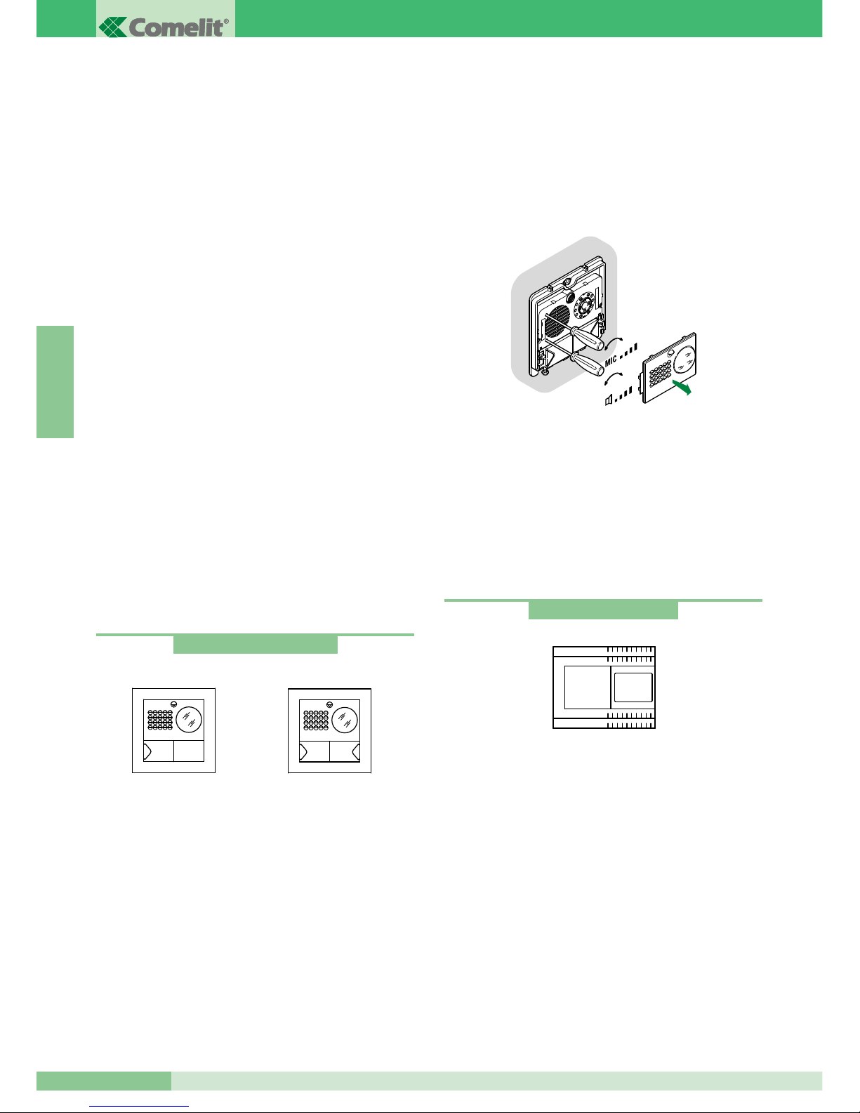
GROUP S.P.A.
MT KIT 04
50
F R A N Ç A I S
GÉNÉRALITÉS
Les Kit Visiophoniques pour un appartement Art. 8171 et deux
appartements Art. 8173 peuvent être utilisés dans des bâtiments
privés ou tertiaires dans lesquels un contrôle efficace de l’accès est
demandé face à de simples opérations d’installation.
En effet, 2 conducteurs suffisent entre la plaque de rue et le/s
moniteur/s interne/s pour activer le système (appel, phonie, vidéo,
auto-allumage) plus deux fils pour alimenter à 12V CA la plaque de
rue et l’électro-serrure.
En outre, une vaste gamme d’accessoires est disponible (catalogue
105 Genius-Kit) pour résoudre facilement chaque exigence
d’installation : en effet, outre des accessoires intéressants de type
standard, il est possible d’agrandir l’installation en ajoutant des
visiophones et/ou des combinés et/ou des plaques de rue.
Il est ainsi possible d’atteindre un nombre maximum de deux plaques
de rue avec trois postes internes entre combinés et visiophones pour
la configuration à un appartement et deux plaques de rue avec six
postes internes entre combinés et visiophones (trois par bouton
d’appel) pour la configuration à deux appartements.
Au moyen de programmations opportunes (comme d’après le
tableau page 64), il est possible d’effectuer des communications
intercommunicantes pour un appartement (c’est-à-dire entre
usagers avec le même code utilisateur) et communications
intercommunicantes pour deux appartements (c’est-à-dire entre
usagers n’ayant pas le même code utilisateur) en utilisant tant les
Visiophones que les combinés parlophoniques. Plusieurs kits
peuvent être reliés à une porte principale Simplebus et/ou à un
standard Art. 1998A.
Voir page 71 pour de plus amples informations.
POSTES EXTÉRIEURS
Caractéristiques techniques
Connexion au moniteur avec 2 fils pour audio, vidéo, ouvre-porte et
appel plus 2 fils pour alimentation par Art. 1205/B.
Caméra orientable à haute sensibilité avec capteur CCD 1/3”.
Éclairage aux infrarouges (6 Leds).
Réglage volum e micro et haut-pa rleur. Bouton d’appel en
aluminium avec étiquette s’extrayant par le devant. Cadre portemodules en aluminium moulé sous pression.
Dimensions boîtier à encastrer : 127x127x45 mm.
Le bouton de l’article 4875/BK est réglé en usine pour effectuer
l’appel à l’adresse 1 alors que pour l’article 4876/BK les boutons
sont programmés pour effectuer des appels aux adresses 1
(bouton de gauche) et 2 (bouton de droite).
Dimensions poste externe : 125x125 mm.
Description bornier
LL connexion moniteur (vidéo, appel, phonie, ouvre-porte)
SE-SE connexion électro-serrure
~ ~ alimentation poste externe
PR borne de programmation
- borne négative à utiliser en phase de programmation
S borne de programmation
RTE entrée ouvre-porte local temporisé OCC., V+ (non utilisées)
Réglage son
Le module de la plaque de rue comprend deux réglages :
volume plaque de rue, indiqué par le symbole du haut-parleur et
réglage du volume du poste interne indiqué par le système du micro.
Réglage orientation caméra
S’il est nécessaire de modifier le réglage de la caméra, procéder
comme indiqué page 51.
1 1 2
Art. 4875/BK - 4876/BK
Art. 4875/BK
Art. 4876/BK
+
-
+
-
Caractéristiques techniques
Le transformateur prévoit 2 sorties : une pour alimenter le poste
externe et l’électro-serrure et une pour alimenter le moniteur.
Dimensions : 105x85x85 mm (6 modules DIN).
Fusible de protection 500 mA retardé.
Description bornier
230 V CA entrée tension de réseau
~~ sortie CA pour poste externe et électro-serrure
+ - sortie 20 V CC d’alimentation du moniteur
Art. 1205/B
Page 53
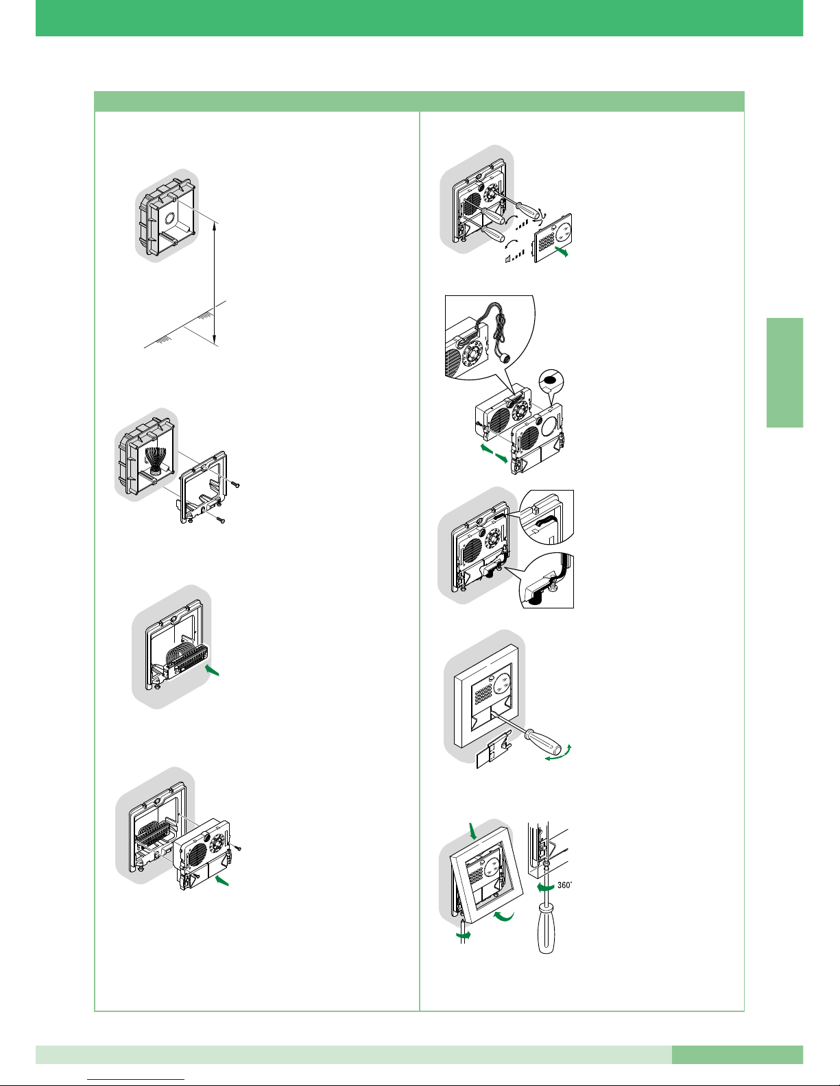
MT KIT 04
51
MT KIT 04
F R A N Ç A I S
• Murer le boîtier à 160÷165 cm
du sol fini,
dans une zone aisée pour voir le
visiteur.
Si possible, ne pas l’orienter
vers le soleil ou vers des
sources de lumière directe
(lampes, surfaces
réfléchissantes, etc.)
• Fixer le châssis sur le boîtier à
encastrer en utilisant les 2 vis
fournies.
• Insérer le bornier et effectuer la
connexion des conducteurs
comme d’après le schéma.
• Insérer le module à
enclenchement sur la borne et le
fixer avec les 2 vis fournies.
160 - 165 cm
Carla
Rossi
+
-
+
-
Carla
Rossi
OPEN
1
2
3
CLOSE
+
-
+
-
MIC
4
5
2
3
1
• Enlever la façade en acier inox
pour effectuer les réglages des
volumes et l’orientation de la
caméra.
NOTE: Desserrer légèrement
les quatre vis pour débloquer
l’orientation de la caméra.
• Position alternative du micro.
• Pour enlever l’étiquette portenoms, insérer dans la fente
centrale la pointe d’un tournevis
et l’extraire.
• Une fois les réglages terminés,
fixer le cadre en agissant sur
les 2 vis inférieures.
NOTE: Pour enlever le cadre,
dévisser les 2 vis inférieures en
effectuant une rotation de 360°
maximum.
Instructions d’installation Art. 4875/BK, 4876/BK
Page 54
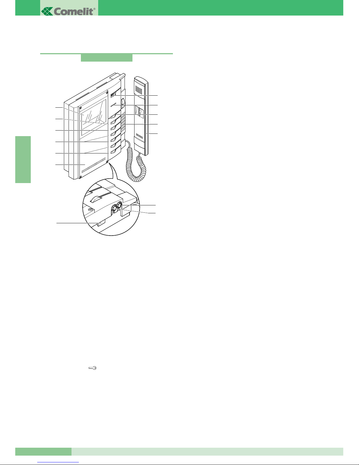
GROUP S.P.A.
MT KIT 04
52
F R A N Ç A I S
POSTES INTÉRIEURS
Caractéristiques techniques du moniteur N/B Art. 5701
Moniteur de la série Bravo de dimensions 212x225x55 mm du
mur, blanc RAL9003 (avec façade personnalisable selon les
préférences de l’utilisateur avec le kit de personnalisation Art.
5727) et avec écran N/B de 4”.
Le moniteur peut également être placé sur une table au moyen
de son support spécial Art. 5712.
1. Réglage volume appel / sélecteur fonction Privacy (par service
Privacy, on entend l’exclusion de l’appel depuis la plaque de
rue et des combinés parlophoniques ou vi s i o p h o n e s
intercommunicants ; l’activation du service Privacy est indiquée
par l’apparition d’un indicateur rouge à côté du sélecteur).
L’utilisateur peut sélectionner la sonnerie du moniteur comme
décrit page 66.
2. Led de signalisation (allumage en fonction de la configuration
adoptée).
3. Bouton ouvre-porte
.
4. Étiquette mémo-boutons sur laquelle indiquer la fonction des
boutons.
5. Combiné Moniteur (soulever le combiné pour commencer la
communication).
6. Écran 4” N/B.
7. Façade de série personnalisable avec le kit de personnalisation.
8. Bouton disponible de série, utilisable pour divers usages (contact
C.NO. 1A max) selon les besoins d’installation ; en retirant CV3 et
CV4 comme indiqué dans la variante BK/P page 89.
9. Bouton disponible de série.
10. Boutons en option (en utilisant la carte Art. 5733 ou Art.
5734) pour l’activation de fonctions supplémentaires.
11. Boutons en option (en utilisant la carte Art. 5733) ou leds de
signalisation en option (en utilisant la carte Art. 5734)
disponibles pour différentes fonctions comme indiqué page 64.
12 Bouton de réglage de la luminosité
(to urner dans le sens des aiguilles d’une montre pour
augmenter la luminosité).
13. Bouton de réglage de l’intensité de la couleur
(to urner dans le sens des aiguilles d’une montre pour
augmenter la valeur).
14. Crochet de fixation.
Possibilité d’utiliser pour le même appartement jusqu’à un
maximum de 3 moniteurs.
Art. 5701
6
1
2
3
4
5
6
8
4
5
3
2
1
9
10
11
7
12
13
14
Page 55
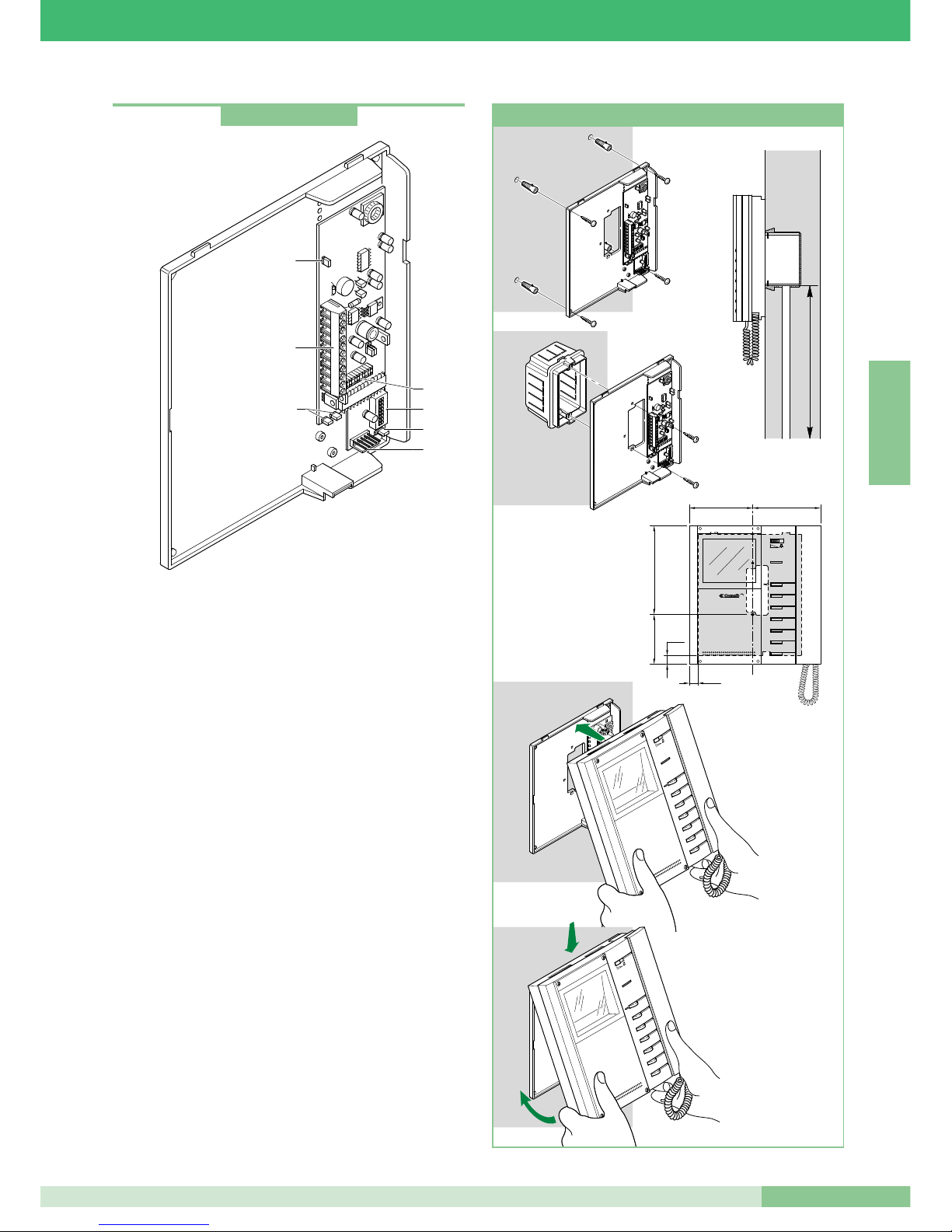
MT KIT 04
53
MT KIT 04
F R A N Ç A I S
Bride de fixation du moniteur
La bride de fixation Art. 5714/K permet d’installer le moniteur en
saillie ou au moyen de la base de table Art. 5712 (pour plus de
détails voir page 52).
Caractéristiques techniques
Dimensions: 170 x 200 x 28 mm.
1. Connecteur Bride Moniteur.
2. Bornes de connexion de l’installation:
0 +20 bornes de connexion à l’Art. 1205/B ou à l’Art. 1212/B.
L L bornes de connexion ligne Bus.
CFP CFP entrée appel palier.
P1 C1 Bouton pour différents usages. Pour avoir un contact libre
C.NO., démonter les jumpers CV3 et CV4 (max 24V - 100mA).
S+ S- Bornes pour le dispositif de répétition de l’appel.
LED1 Entrée pour la gestion de l’éclairage de la Led de
signalisation (en présence d’un signal sur cette borne, la led
clignote; voir variante BK/N page 89).
3. Microswitches de programmation.
4. Jumper CV5 de débranchement du signal vidéo.
5. Jumper CV3 et CV4 (à démonter pour avoir un contact libre
C.NO. sur les bornes P1C1).
6. Connecteur pour la connexion de la carte supplémentaire en
option Art. 5733 ou Art. 5734.
7. Jumper JP1. S’utilise pour régler la bride du Moniteur comme
Principale ou Secondaire (voir page 63).
1 2 3
4
ON
5 6 7
8
DIP
4
2
1
5
6
7
3
Art. 5714/K
1
2
3
4
5
6
cm 10,2 cm 11
cm 14,4
cm 8,1
145 cm
CV2
CV7
CV1
CV6
CV5
CV3
CV4
1
2
3
4
5
6
CV2
CV7
CV1
CV6
CV5
CV3
CV4
1
2
3
4
5
6
1
2
cm 1,4
cm 1,4
12 3
4
ON
56 7
8
DIP
12 3
4
ON
56 7
8
DIP
Installation du moniteur Art. 5701 en saillie
Page 56
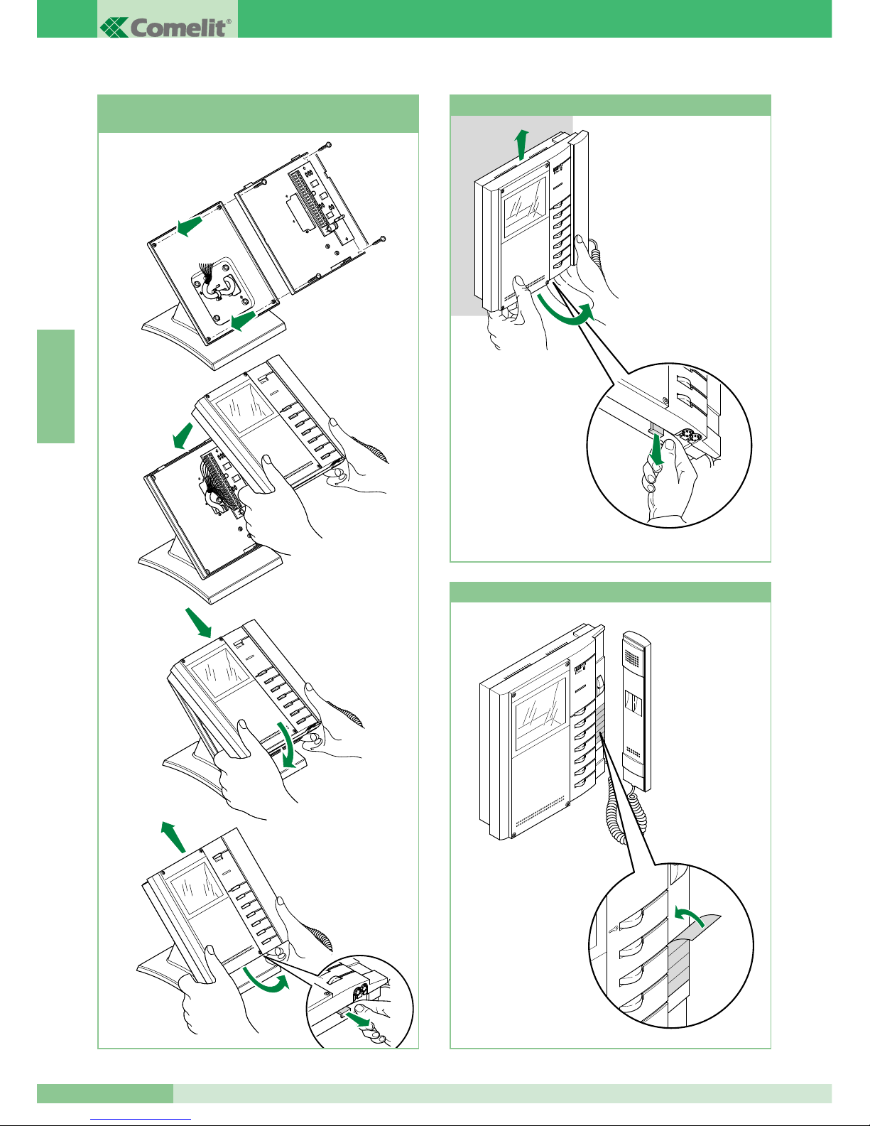
GROUP S.P.A.
MT KIT 04
54
F R A N Ç A I S
1
2
3
4
5
6
1
1
2
3
4
5
6
2
3
6
5
4
3
2
1
6
5
4
Installation moniteur Art. 5701 sur la base
de table Art. 5712
1
2
3
4
5
6
3
2
1
Procédure pour enlever le moniteur
1
2
3
4
5
6
1
2
Positionnement étiquette sur moniteur
Page 57
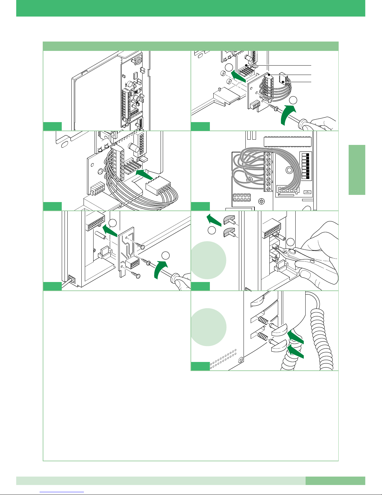
MT KIT 04
MT KIT 04
55
F R A N Ç A I S
1 2 3
4
ON
5 6 7
8
DIP
CV3
1 2 3 4
ON
5 6 7
DIP
CV4
1
2
1
2
3
1
4
5734
5734 !
2
1
6
3
4
5
6
5734 !
7
1 Retirer la bride et la carte en option de leur emballage.
2 Visser la carte en option, avec les vis prévues à cet effet, sur le
support en matière plastique de la bride.
1. Boîte à bornes:
P3: Contact bouton 3 du moniteur. *
C3: Contact commun bouton 3 du moniteur *. Commun
principal venant de la bride Art. 5714/K (débrancher le fil
vers le connecteur de la bride pour libérer tous les contacts
communs).
P4: Contact bouton 4 du moniteur. *
C4: Contact commun bouton 4 du moniteur. *
+P5: Contact bouton 5 du moniteur pour Art. 5733 *.
Entrée positive led 5 pour Art. 5734.
-C5: Contact commun bouton 5 du moniteur po u r
Art. 5733 *. Entrée négative led 5 pour Art 5734.
+P6: Contact bouton 6 du moniteur pour Art. 5733 *.
Entrée positive led 6 pour Art. 5734.
-C6: Contact commun bouton 6 du moniteur pour Art. 5733 *.
Entrée négative led 6 pour Art 5734.
2. Connecteur mâle bride.
3. Connecteur femelle Art. 5733 ou Art. 5734.
3 Brancher le connecteur femelle de la carte en option au
connecteur mâle situé sur la bride.
4 Placer les fils entre la carte en option et la bride, de la manière
indiquée dans la figure.
5 À l’aide des vis prévues à cet effet, fixer la carte en option avec
le connecteur sur le dos du moniteur.
6 Seulement pour la carte en option Art. 5734: couper et retirer
les boutons 5 et 6 du moniteur.
7 Seulement pour la carte et option Art. 5734: introduire les
boutons transparents qui se trouvent dans l’emballage de
l’article, dans les positions des boutons 5 et 6, comme indiqué
dans la figure.
*
Pour utiliser le bouton comme contact C.NO. (24V-100mA max), retirer le
fil vers le connecteur de la bride et dégager le commun correspondant.
CV3
1
2
3 4
ON
5
6
7 8
DIP
CV4
3
1
2
5
Installation carte en option Art. 5733, Art. 5734
2
Page 58

GROUP S.P.A.
MT KIT 04
56
F R A N Ç A I S
Instructions pour installation combiné parlophonique Style Art. 2608, 2628 et 2610
Façade interchangeable disponible pour les Art. 2628 et Art. 2610
1
2
145 cm
4A 4B
95mm
47,5mm
75,5mm
215mm
1
1
1
1
1
2
3
1
4
2
2
5
6
2
4
6
1
3
5
7
9
2
8
CH2
7
1
2
4C
Page 59

MT KIT 04
57
MT KIT 04
F R A N Ç A I S
+
-
MIC
1 2 3 4 5 6 7 8
c
A
JP1
Combiné parlophonique Basic avec 2 boutons de série.
Non utilisable pour la fonction intercommunicante.
Le combiné parlophonique doit être monté en utilisant l’Art. 1214/2
comme l’indique le schéma de connexion BK/D page 85.
1. Bouton ouvre-porte .
2. Bouton P1 appel standard / actionneur générique / bouton pour
usages divers présent sur le bornier (P1 C1).
3. Sélecteur sonnerie/service Privacy à 3 positions :
Position haute : sonnerie volume maximum.
position centrale : sonnerie volume moyen.
Position basse : activation de la fonction Privacy
(Le Service Privacy exclut l’appel de la plaque de rue ou du
standard de conciergie ; l’activation de la fonction Privacy est
indiquée par l’apparition d’un indicateur rouge en haut à droite).
4. Voyant de la fonction Privacy.
5. Bornes pour le raccordement de l’installation :
L L connexion à la ligne bus.
CFP CFP entrée de l’appel depuis l’étage.
P1 C1 bornes bouton P1 C. NO. 24V 100mA dédié aux services
divers (enlever CV1 et CV2).
S+ S- bornes pour le dispositif de répétition de l’appel.
6. JP1 jumper pour sélectionner la fonction Appel standard
(position C) / Actionneur générique (position A) du bouton P1
(voir figure ci-contre).
7. CV1 CV2 jumper à retirer pour avoir un contact libre C. NO.
sur le bouton P1.
8. Microswitches pour la programmation du code usager (voir
tableau page 63).
9. Potentiomètre de réglage du volume du microphone.
Nettoyer avec un chiffon humidifié avec de l’eau. Éviter
d’utiliser de l’alcool ou d’autres produits agressifs.
Combiné parlophonique Style Art. 2608
3
9
8
5
7
6
4
1
2
Page 60

GROUP S.P.A.
MT KIT 04
58
F R A N Ç A I S
Combiné parlophonique Elegance avec fonctions et boutons
supplémentaires.
Non utilisable pour la fonction intercommunicante.
Le combiné parlophonique doit être monté en utilisant l’Art. 1214/2
comme l’indique le schéma de connexion BK/D page 85.
Important : pour la définition correcte de l’article en phase
d’installation dans un système BRAVO KIT, se référer à la
remarque ci-dessous.
1. Sélecteur sonnerie/service Privacy à 3 positions :
Position haute : sonnerie volume maximum.
position centrale : sonnerie volume moyen.
Position basse : activation de la fonction Privacy
(par service Privacy on entend l’exclusion de l’appel du poste
externe ou standard ; l’activation de la fonction Privacy est
indiquée par l’apparition d’un indicateur rouge en haut à droite).
2. Voyant de la fonction Privacy.
3. Bouton 1 disponible de série pour la fonction Actionneur.
4. Bouton ouvre-porte .
5. Bouton 2 disponible de série pour la fonction d’appel du
central de conciergerie.
6. Bouton 3 pour diverses utilisations présent dans le bornier
(P3 C3).
7. Boutons C. NO. ou Led (MAXIMUM 3) en option pour
fonctions supplémentaires. (A)
8. Façade interchangeable Fig. 7 page 56.
9. Étiquette mémo-boutons sur laquelle on peut indiquer la
fonction des boutons du combiné parlophonique (à appliquer
sous la façade interchangeable) Fig. 7 page 56.
10. Combiné de l’appareil (saisir le combiné pour commencer la
communication).
(A) Bouton disponible avec carte en option Art. 1626.
Voyant de signal disponible avec la carte en option Art. 1627.
11. Bornes pour le raccordement de l’installation :
L L connexion à la ligne bus.
CFP CFP entrée de l’appel depuis l’étage.
P3 C3 bornes bouton P3 C. NO. 24V 100mA dedié aux
services divers.
S+ S- bornes pour le dispositif de répétition de l’appel.
12. JP1 Jumper pour la sélection entre modalité Simplebus 1 et
Simplebus 2.
13. Microswitches U2 pour la programmation du code usager (voir
tableau page 63).
14. Potentiomètre de réglage du volume du microphone.
Nettoyer avec un chiffon humidifié avec de l’eau. Éviter
d’utiliser de l’alcool ou d’autres produits agressifs.
ATTENTION !
POUR UTILISER LE COMBINÉ PARLOPHONIQUE ART. 2628 DANS DES INSTALLATIONS
BRAVOKIT, IL EST NÉCESSAIRE DE DÉPLACER LE CAVALIER JP1 EN POSITION S1
S1
1
3
2
5
4
7
6
9
8
Combiné parlophonique Style Art. 2628
JP1
14
13
11
12
8
3
6
7
9
7
5
4
2
1
10
8
3
6
7
9
7
5
4
2
1
10
Page 61

MT KIT 04
59
MT KIT 04
F R A N Ç A I S
1
3
2
5
4
7 6
9
8
Combiné parlophonique Elegance avec fonctions et boutons
supplémentaires et service intercommunicant.
L’Art. 2610 a la possibilité (par paramétrage spécial) de gérer des
communications intercommunicantes et d’autres fonctions
supplémentaires (voir tableau récapitulatif page 64).
Le combiné parlophonique doit être monté en utilisant l’Art. 1214/2
comme l’indique le schéma de connexion BK/D page 85.
1. Sélecteur sonnerie/service Privacy à 3 positions :
Position haute : sonnerie volume maximum.
position centrale : sonnerie volume moyen.
Position basse : Activation du service Privacy
(par service Privacy on entend l’exclusion de l’appel du poste
externe ou standard ; l’activation de la fonction Privacy est
indiquée par l’apparition d’un indicateur rouge en haut à
droite).
2. Voyant de la fonction Privacy.
3. Led de signalisation (disponible de série).
4. Bouton ouvre-porte .
5. Bouton 1 disponible de série (programmable avec différentes
fonctions, voir tableau page 67. Programmé en usine pour la
fonction Actionneur générique).
6. Bouton 2 disponible de série (libre ou programmable avec
différentes fonctions, voir tableau page 67).
Programmé en usine pour fonction appel à standard.
7. Boutons C. NO. ou Led (MAXIMUM 3) en option pour
fonctions supplémentaires. (A)
8. Façade interchangeable Fig. 7 page 56.
9. Étiquette mémo-boutons sur laquelle on peut indiquer la
fonction des boutons du combiné parlophonique (à appliquer
sous la façade interchangeable) Fig. 7 page 56.
10. Combiné de l’appareil (saisir le combiné pour commencer la
communication).
(A) Bouton disponible avec carte en option Art. 1626.
Voyant de signal disponible avec c a r t e en option
Art. 1627.
11. Bornes pour le raccordement de l’installation :
L L connexion à la ligne bus.
CFP CFP entrée de l’appel depuis l’étage.
P2 C2 bornes bouton P2 C. NO. 24V 100mA dédié aux
services divers (enlever CV2 et CV3).
S+ S- bornes pour le dispositif de répétition de l’appel.
12. JP1 Jumper pour la sélection entre modalité Simplebus 1 et
Simplebus 2.
13. CV3 CV2 Jumper à retirer pour disposer du bouton P2 C. NO.
14. Microswitches U2 pour la programmation du code usager (voir
tableau page 63).
15. Microswitches U4 pour la programmation des boutons P1 et P2
(voir tableau page 67).
16. Potentiomètre de réglage du volume du microphone.
Nettoyer avec un chiffon humidifié avec de l’eau. Éviter
d’utiliser de l’alcool ou d’autres produits agressifs.
Combiné parlophonique Style Art. 2610
16
14
15
13
11
12
8
3
6
7
9
7
5
4
2
1
10
Page 62
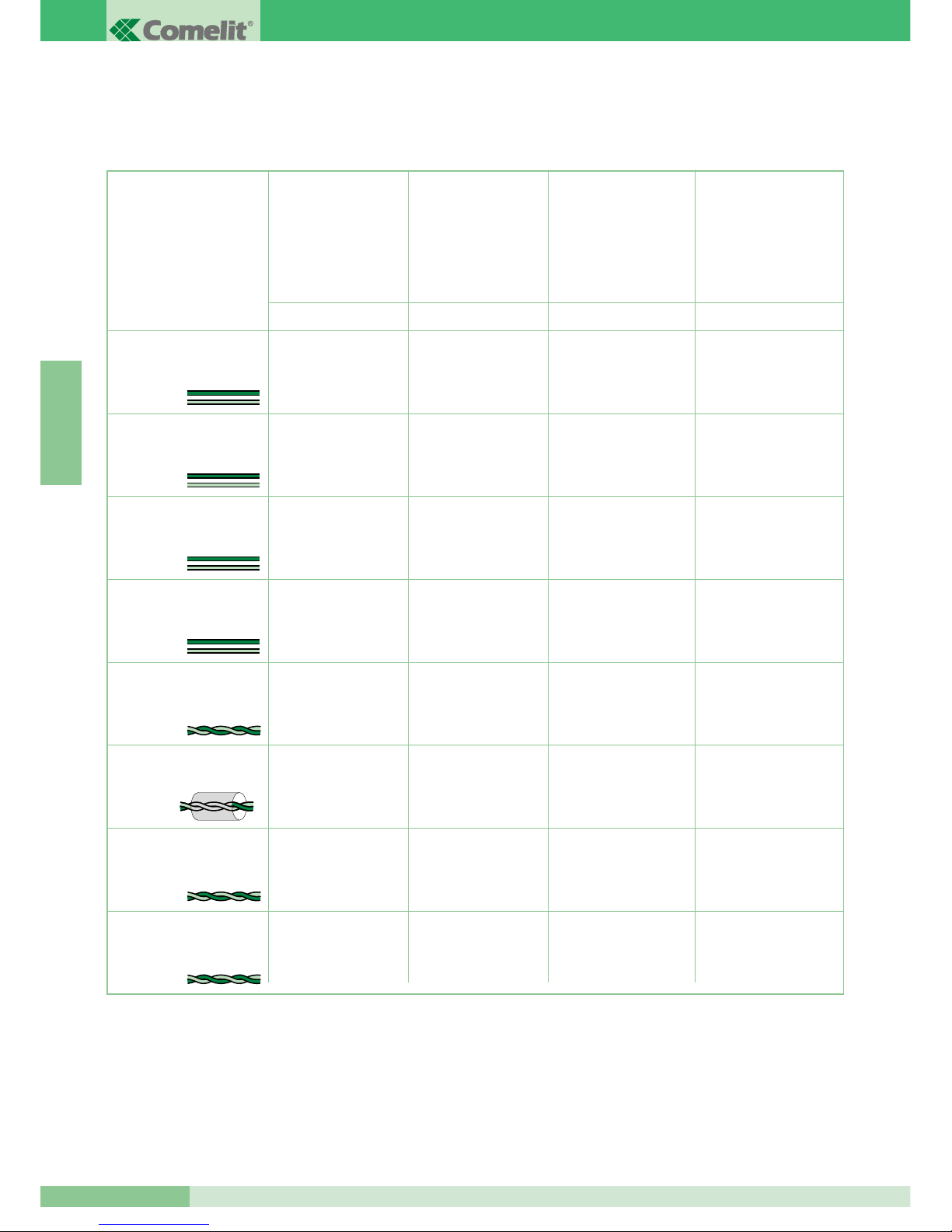
GROUP S.P.A.
MT KIT 04
60
F R A N Ç A I S
Distance maximum entre
poste externe 4875/BK ou
4876/BK et le 4833/A ou
1214/2 le plus éloigné.
Distance maximum entre
4833/A et le 1214/2
le plus éloigné
Distance maximum entre le
moniteur et le 1214/2
Cette section du manuel comprend toutes les indications concernant la phase d’installation du système BRAVO KIT.
La distance maximum totale entre le poste externe et le moniteur le plus éloigné est de 400 m.
INDICATIONS GÉNÉRALES D’INSTALLATION ET FONCTIONNEMENT
Section ou type de câble Distance maximum
entre alimentation
1205/B ou 1395
et poste externe
4875/BK et 4876/BK
Distance maximum
entre alimentation
1205/B ou 1212/B
et moniteur alimenté
A/G B/E C/F D
Câble bifilaire (sect. 0,5 mm
2
Ø 0,8 mm AWG 20)**
Câble bifilaire (sect. 1 mm
2
Ø 1,2 mm AWG 17)**
Câble bifilaire (sect. 1,5 mm
2
Ø 1,4 mm AWG 15)**
Câble bifilaire (sect. 2,5 mm
2
Ø 1,8 mm AWG 13)**
Boucle téléphonique twistée
(sect. 0,28 mm2 Ø 0,6 mm
AWG 23)*
Câble tressé et blindé (sect.
1 mm2 Ø 1,2 mm
AWG 17)*
UTP5 Cat 5 (sect. 0,2 mm
2
Ø 0,5 mm AWG 24)*
Câble Comelit Art. 4576
et Art. 4578 (sect. 0,5 mm
2
Ø 0,8 mm AWG 20)*
* Lorsque l’on utilise un câble multipaires torsadées, on doit utiliser uniquement une paire torsadée disponible.
S’il est nécessaire de diminuer les chutes résistives, utiliser la paire torsadée comme un fil simple.
** Dans le cas d’un câble multifils, il ne faut utiliser que deux des fils disponibles et ne jamais mettre plusieurs fils en parallèle.
20 m
(65 feet)
40 m
(130 feet)
60 m
(195 feet)
100 m
(325 feet)
25 m
(85 feet)
50 m
(165 feet)
100 m
(325 feet)
150 m
(495 feet)
150 m
(495 feet)
150 m
(495 feet)
150 m
(495 feet)
150 m
(495 feet)
100 m
(325 feet)
150 m
(495 feet)
150 m
(495 feet)
40 m
(130 feet)
40 m
(130 feet)
40 m
(130 feet)
40 m
(130 feet)
20 m
(65 feet)
40 m
(130 feet)
50 m
(165 feet)
Page 63
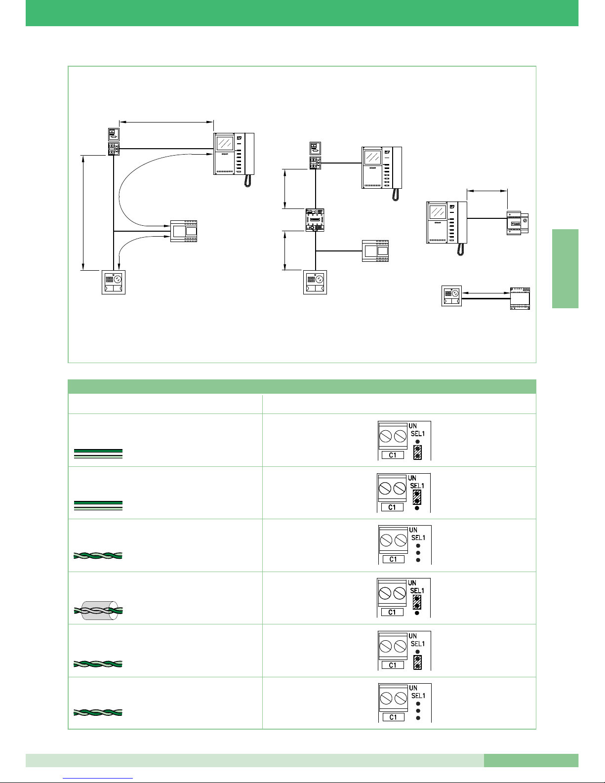
MT KIT 04
61
MT KIT 04
F R A N Ç A I S
4875/BK
4876/BK
1205/B
1214/2
1216
C
A
B
D
4875/BK
4876/BK
1214/2
1216
F
F
4833/A
1212/B
E
1205/B
1395
4875/BK
4876/BK
G
Type de câble Programmation Art. 1216
Câble bifilaire (sect. 1,5 mm2 Ø 1,4 mm AWG 15)
Câble bifilaire (sect. 1 mm2 Ø 1,2 mm AWG 17)
Boucle téléphonique twistée
(sect. 0,28 mm2 ( Ø 0,6 mm AWG 23)
Câble UTP5 cat. 5
(sect. 0,2 mm2 Ø 0,5 mm AWG 24)
2
1
Câble Comelit Art. 4576 et Art. 4578 (sect. 0,5 mm
2
Ø 0,8 mm AWG 20)
Câble bifilaire
(sect. 0,5 mm2 Ø 0,8 mm AWG 20)
2
Câble tressé et blindé
(sect. 1 mm2 Ø 1,2 mm AWG 17)
1
Tableau programmations de l’Art. 1216 en fonction du type de câble de connexion utilisé
Page 64
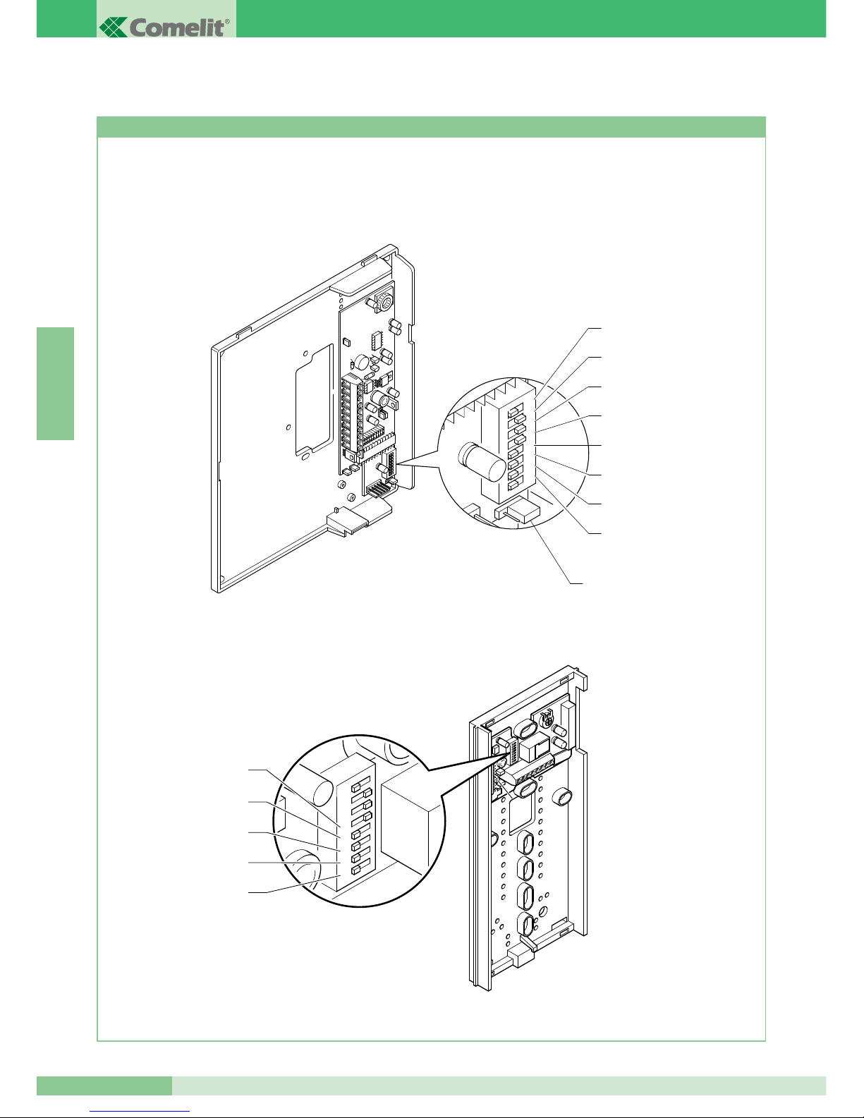
MT KIT 04
62
GROUP S.P.A.
F R A N Ç A I S
1 2 3
4
ON
5 6 7
8
DIP
1 2 3
4
ON
5 6 7
8
DIP
S1-8
S1-7
S1-6
S1-4
S1-3
S1-2
S1-1
S1-5
JP1
Réglages bride 5714/K et combinés parlophoniques Style Art. 2608, 2628 et 2610
RÉGLAGE ET DESCRIPTION FONCTIONNEMENT SYSTÈME BRAVO KIT
La figure suivante illustre la position des microswitches et du Jumper JP1 de la bride 5714/K et des microswitches des combinés
parlophoniques Style Art. 2608, 2628 et 2610.
1 2 3 4 5 6 7 8
S1-5
S1-4
S1-3
S1-2
S1-1
Page 65
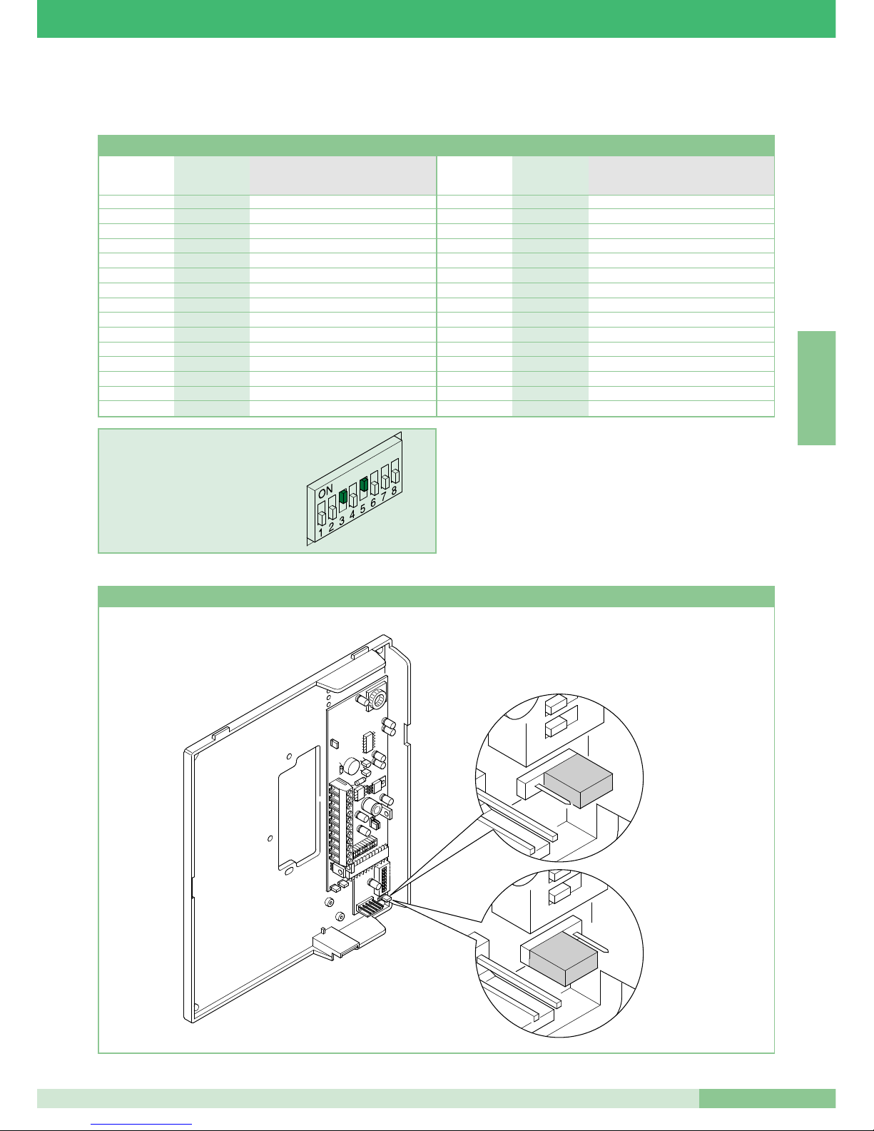
63
MT KIT 04
MT KIT 04
F R A N Ç A I S
Programmation bride Art. 5714/K principale ou secondaire
Les valeurs de S1-1, S1-2, S1-3, S1-4 et S1-5 définissent l’adresse d’appel.
Pour le codage des brides et des combinés parlophoniques, se référer au tableau suivant.
ATTENTION : SUR COMBINÉS PARLOPHONIQUE 2608, 2628 ET
2610 POSITIONNER SUR OFF I DIP 6, 7, 8
L’appel intercommunicant deux appartements (entre les
combinés parlophoniques et/ou les visiophones) n’est possible
que si les deux usagers sont réglés sur des codes d’appel
contigus (marqués par la même lettre AA...CC..YY dans le
tableau de programmation des microswitches illustré ci-dessus).
Tableau de programmation des microswitches pour code usager sur brides et combinés parlophoniques
EXEMPLE introduction code 20.
H 16 5
I 17 1,5
I 18 2,5
J 19 1,2,5
J 20 3,5
K 21 1,3,5
K 22 2,3,5
L 23 1,2,3,5
L 24 4,5
M 25 1,4,5
M 26 2,4,5
N 27 1,2,4,5
N 28 3,4,5
O 29 1,3,4,5
O 30 2,3,4,5
A 1 1
A 2 2
B 3 1,2
B 4 3
C 5 1,3
C 6 2,3
D 7 1,2,3
D 8 4
E 9 1,4
E 10 2,4
F 11 1,2,4
F 12 3,4
G 13 1,3,4
G 14 2,3,4
H 15 1,2,3,4
Référence pour
intercommunicant Code usager Microswitches sur ON
deux appartements
Référence pour
intercommunicant Code usager Microswitches sur ON
deux appartements
1 2 3
4
ON
5 6 7
8
DIP
1 2
ON
1
ON
Principale
Secondaire
Page 66
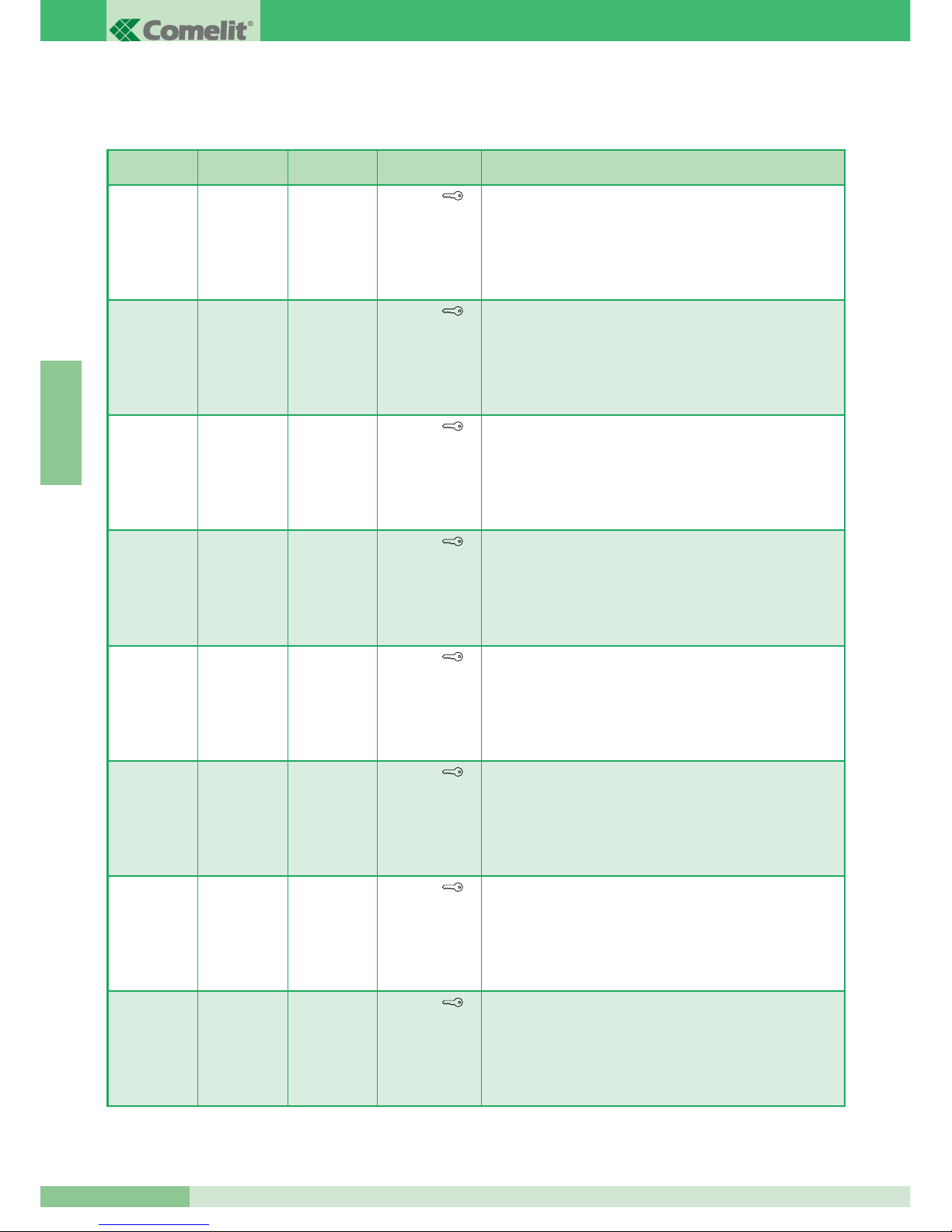
GROUP S.P.A.
MT KIT 04
64
F R A N Ç A I S
OFF
(0)
OFF
(0)
OFF
(0)
S1-6 S1-7 S1-8 Fonctions touches
Bouton
Bouton 1
Bouton 2
Bouton 3
Bouton 4
Bouton 5
Bouton 6
Ouvre-porte
Actionneur / Bouton libre
Éclairage intérieur / Demande vidéo
Appel au standard
Appel intercommunicant un appartement
Appel intercommunicant deux appartements
(1)
Gestion fonction Docteur
ON
(1)
OFF
(0)
OFF
(0)
Bouton
Bouton 1
Bouton 2
Bouton 3
Bouton 4
Bouton 5
Bouton 6
Ouvre-porte
Appel intercommunicant un appartement
Appel intercommunicant deux appartements
Appel au standard
Appel intercommunicant un appartement
Appel intercommunicant deux appartements
(1)
Gestion fonction Docteur
OFF
(0)
ON
(1)
OFF
(0)
Bouton
Bouton 1
Bouton 2
Bouton 3
Bouton 4
Bouton 5
Bouton 6
Ouvre-porte
Appel intercommunicant un appartement
Gestion fonction Docteur
Appel au standard
Appel intercommunicant un appartement
Appel intercommunicant deux appartements
(1)
Gestion fonction Docteur
ON
(1)
ON
(1)
OFF
(0)
Bouton
Bouton 1
Bouton 2
Bouton 3
Bouton 4
Bouton 5
Bouton 6
Ouvre-porte
Appel intercommunicant deux appartements
Gestion fonction Docteur
Appel au standard
Appel intercommunicant un appartement
Appel intercommunicant deux appartements
(1)
Gestion fonction Docteur
OFF
(0)
OFF
(0)
ON
(1)
Bouton
Bouton 1
Bouton 2
Bouton 3
Bouton 4
Bouton 5
Bouton 6
Ouvre-porte
Appel intercommunicant un appartement
Éclairage intérieur / Demande vidéo
Appel au standard
Appel intercommunicant un appartement
Appel intercommunicant deux appartements
(1)
Gestion fonction Docteur
ON
(1)
OFF
(0)
ON
(1)
Bouton
Bouton 1
Bouton 2
Bouton 3
Bouton 4
Bouton 5
Bouton 6
Ouvre-porte
Appel intercommunicant deux appartements
Éclairage intérieur / Demande vidéo
Appel au standard
Appel intercommunicant un appartement
Appel intercommunicant deux appartements
(1)
Gestion fonction Docteur
OFF
(0)
ON
(1)
ON
(1)
Bouton
Bouton 1
Bouton 2
Bouton 3
Bouton 4
Bouton 5
Bouton 6
Ouvre-porte
Appel au standard
Éclairage intérieur / Demande vidéo
Appel au standard
Appel intercommunicant un appartement
Appel intercommunicant deux appartements
(1)
Gestion fonction Docteur
ON
(1)
ON
(1)
ON
(1)
Bouton
Bouton 1
Bouton 2
Bouton 3
Bouton 4
Bouton 5
Bouton 6
Ouvre-porte
Appel au standard
Commande actionneur
Appel au standard
Appel intercommunicant un appartement
Appel intercommunicant deux appartements
(1)
Gestion fonction Docteur
La valeur de S1-6, S1-7 et S1-8 (uniquement pour bride Art. 5714/K) définit la modalité opérationnelle dans laquelle opère le système Bravo
KIT, comme indiqué dans le tableau suivant.
(1)
L’appel intercommunicant deux appartements (entre les combinés parlophoniques et/ou les visiophones) n’est possible que
si les deux usagers sont réglés sur des codes d’appel contigus (marqués par la même lettre AA…CC..YY dans le tableau de
programmation des microswitches illustré page 63).
Page 67

MT KIT 04
65
MT KIT 04
F R A N Ç A I S
MICROSWITCHES S1-1, S1-2, S1-3, S1-4 E S1-5
Les valeurs des microswitches S1-1, S1-2, S1-3, S1-4 et S1-5
définissent l’adresse d’appel de la bride en objet, par rapport à la
plaque de rue d’appel.
Pour utiliser la fonction d’appel intercommunicant deux appartements
(combinés parlophoniques et/ou visiophones), les usagers doivent
être réglés sur des adresses d’appel contiguës, indiquées dans le
tableau illustré page 63 avec la même lettre (AA…CC….YY).
Fonctionnement
• Lorsque le visiteur appuie sur le bouton d’appel, la led à
l’infrarouge s’allume pour éclairer la personne, la sonnerie interne
d’appel s’enclenche (si la fonction privacy n’est pas validée) et
l’image s’affiche au moniteur principal, ou aux moniteurs
principaux, pendant environ 60”.
Au contraire, s’il entre en communication, la durée maximum de
la conversation pourra être de 90’’.
La plaque de rue émet une tonalité indiquant que l’appel a eu lieu
; lorsque, dans les installations à 2 entrées ou plus, au moment
de l’appel la plaque de rue émet une tonalité d’occupé au lieu de
la sonnerie, cela signifie qu’une autre conversation est en cours
vers une autre plaque de rue.
En cas de court-circuit persistant sur la ligne bus, le poste
externe émet un signal sonore intermittent d’avertissement.
• La conversation au poste interne a lieu en soulevant le combiné.
• La commande de luminosité est placée sur le côté inférieur du
Moniteur, alors que la commande de réglage du volume de la
sonnerie ou d’activation de la fonction Privacy est située sur la
partie haute.
• La touche portant le symbole de la clé sur le moniteur agit sur
l’électro-serrure en l’activant pendant 2 secondes environ.
• L’auto-allumage du moniteur principal s’effectue en appuyant sur
le Bouton 2 lorsque la fonction est validée (voir la description
page 67).
Dans les installations équipées de 2 postes externes, il est
possible de visualiser alternativement l’image depuis un poste
externe ou depuis l’autre (fonction “basculer”) en appuyant sur le
bouton 2.
Il n’est pas possible d’auto-allumer le moniteur durant une autre
conversation.
• Pour les fonctions d’intercommunication du système BRAVO KIT,
voir la page 64.
• Pour la programmation d’adresses usagers différentes de celles
programmées d’origine (1 et 2), voir page 69.
Moniteurs supplémentaires principaux ou secondaires
La programmation de JP1 définit si la bride en objet sera gérée
comme principale ou comme secondaire. La plaque de rue peut
gérer jusqu’à un ma ximum de 3 visiophones ou Combinés
parlophoniques par bouton d’appel. Lorsque l’on effectue un appel
depuis la plaque de rue, le moniteur que le système allumera sera
celui du visiophone principal.
Les autres moniteurs secondaires de la même unité familiale
resteront éteints. En répondant à l’appel de la plaque de rue depuis
un visiophone secondaire, l’image est automatiquement visualisée
sur le moniteur.
À ce stade, le moniteur du visiophone principal s’éteint et l’image
s’affiche au moniteur du visiophone sur lequel on a appuyé sur le
Bouton 2 - Demande vidéo.
Même sans soulever le combiné, il est possible de visualiser
l’image transmise de la plaque de rue toujours en appuyant sur le
Bouton 2 - Demande vidéo .
Dans la configuration classique de BRAVO KIT, on peut donc avoir
au maximum 2 visiophones secondaires et 1 visiophone principal
par bouton d’appel, tous alimentés par le même Art. 1205/B
(Variante BK/C page 84).
On a la possibilité de gérer jusqu’à 3 visiophones principaux au sein
de la même unité familiale (c’est-à-dire programmés sur le même
code usager).
Dans cette configuration particulière, les visiophones principaux
supplémentaires devront être alimentés chacun par l’Art. 1212/B
(Variante BK/H et BK/I page 83, 84).
Avec l’appel de la plaque de rue, l’image sera visualisée sur chaque
visiophone principal relié au système.
Nous rappelons que, même en utilisant l’Art. 1212/B, le nombre
maximum de visiophones pouvant être reliés pour la même unité
familiale est de 3.
Une alimentation dédiée n’est nécessaire pour aucun combiné
parlophonique en option.
S1-6, S1-7, S1-8
Réglage de la modalité de fonctionnement BRAVO KIT
Le tableau illustré page 64 indique les fonctions de chaque bouton du
Moniteur, en fonction du réglage des microswitches S1-6, S1-7, S1-8.
Rappelons que le bouton , le bouton 1 et le bouton 2 sont de
série, alors que le bouton 3, le bouton 4, le bouton 5 et le bouton 6
sont en option, en utilisant la carte Art. 5733.
En outre, l’Art. 5734 permet de disposer du Bouton 3 et du Bouton
4, ainsi que de deux leds de signalisation dans les positions du
Bouton 5 et du Bouton 6.
Ces leds de signalisation peuvent être utilisées par l’installateur
pour différentes exigences d’installation et elles ne sont pas gérées
de manière automatique par la bride du Moniteur.
Description fonctions boutons
Ouvre-porte La pression du bouton Ouvre-porte active la
serrure de la plaque de rue.
Actionneur La pression du Bouton programmé dans la
modalité Actionneur permet d’activer l’Art. 1256 qui peut être utilisé
par exemple pour activer l’ouverture de portails, portes basculantes
ou pour l’activation du module caméras cycliques Art. 1259/A.
Bouton Libre L’indication Bouton libre indique la possibilité
d’utiliser le bouton comme contact C.NO. en bornier au moyen de
programmations opportunes comme illustré dans la variante BK/P
page 89.
Page 68
GROUP S.P.A.
MT KIT 04
66
F R A N Ç A I S
Auto-allumage / Demande Vidéo La pression du Bouton 2
dans cette modalité permet de visualiser sur l’écran du moniteur
l’image transmise depuis la plaque de rue même si aucun appel n’a
été effectué.
Pour utiliser et valider le service, voir variante BK/P page 89. Dans
les installations équipées de deux postes externes, il est possible
de visualiser alternativement l’image depuis un poste externe ou
depuis l’autre (fonction “basculer”) en appuyant sur le bouton.
Sur les Moniteurs secondaires, le bouton 2 a la fonction de
demande vidéo (pour plus de détails, voir à la page 67).
Appel au Standard Appuyer sur le Bouton réglé sur cette
modalité pour envoyer un appel au standard de conciergerie de
l’installation.
Appel intercommunicant un appartement Appuyer sur le
Bouton réglé sur cette modalité pour envoyer un appel aux autres
appareils (V isiophones et / o u Combin é s parlophoniques)
programmés sur la même adresse d’appel.
En saisissant le combiné, le destinataire de l’appel engage la
communication avec l’appelant.
La communication prend fin lorsque le combiné est raccroché.
Quel que soit le cas de figure, un appel provenant d’une unité
extérieure est toujours prioritaire sur une communication
intercommunicante. Dans ce cas, l e s utilisateurs d é j à en
communication entendent dans le combiné un signal sonore
similaire à un signal d’appel si ce dernier leur est destiné, ou un
triple signal sonore dans le cas contraire.
Pour prendre l’appel provenant de l’unité extérieure, il suffit de
saisir le combiné d’une unité disponible ou de raccrocher, puis de
saisir le combiné d’une unité occupée par une communication
intercommunicante.
L’activation de la communication avec l’unité extérieure interrompt
la conversation interne en cours.
Un appel intercommunicant n’est pas prioritaire su r une
conversation/un appel avec l’unité extérieure.
Dans ce cas, lors d’une tentative d’appel intercommunicant, le
voyant clignote pendant quelques secondes pour indiquer que le
système est occupé.
Appel intercommunicant deux appartements Appuyer sur le
Bouton réglé sur cette modalité pour envoyer un appel aux autres
appareils (V isiophones et / o u Combin é s parlophoniques)
programmés sur l’adresse d’appel à deux usagers par rapport à sa
propre adresse, comme indiqué dans le tableau illustré page 63.
En saisissant le combiné, le destinataire de l’appel engage la
communication avec l’appelant. La communication prend fin
lorsque le combiné est raccroché.
Quel que soit le cas de figure, un appel provenant d’une unité
extérieure est toujours prioritaire sur une communication
intercommunicante.
Dans ce cas, les utilisateurs déjà en communication entendent
dans le combiné un signal sonore similaire à un signal d’appel si ce
dernier leur est destiné, ou un triple signal sonore dans le cas
contraire.
Pour prendre l’appel provenant de l’unité extérieure, il suffit de
saisir le combiné d’une unité disponible ou de raccrocher, puis de
saisir le combiné d’une unité occupée par une communication
intercommunicante.
L’activation de la communication avec l’unité extérieure interrompt
la conversation interne en cours.
Un appel intercommunicant n’est pas prioritaire su r une
conversation/un appel avec l’unité extérieure.
Dans ce cas, lors d’une tentative d’appel intercommunicant, le
voyant clignote pendant quelques secondes pour indiquer que le
système est occupé.
Gestion fonction Docteur La fonction Docteur permet
l’actionnement automatique de l’ouvre-porte sur un appel à
l’adresse du visiophone et/ou du combiné parlophonique lorsque la
fonction a été activée, venant de la plaque de rue.
Lorsque la fonction est active, la led de signalisation reste allumée.
Pour valider ou invalider la fonction Docteur, appuyer pendant 2
secondes sur le bouton programmé pour cette fonction.
Opérations pour sélectionner la sonnerie Moniteur
L’usager peut sélectionner la sonnerie du Moniteur dans une liste
de sonneries disponibles, en suivant la procédure ci-dessous :
(1) Maintenir le bouton appuyé jusqu’à ce qu’une tonalité
de confirmation soit audible (cette opération n’est possible
que lorsque le système est en condition de repos ; dans le
cas contraire, la led de signalisation clignote pour avertir
l’utilisateur).
(2) Appuyer et relâcher le Bouton :
1 fois (émission d’une tonalité de confirmation) pour modifier la
sonnerie d’appel de la plaque de rue.
2 fois (émission de 2 tonalités de confirmation) pour modifier la
sonnerie depuis standard.
3 fois (émission de 3 tonalités de confirmation) pour modifier la
sonnerie de l’appel palier.
Appuyer de nouveau sur le bouton pour répéter la
séquence décrite ci-dessus.
Après avoir appuyé sur le bouton pour la dernière fois,
attendre le signal de confirmation avant de passer à l’étape
suivante.
(3) Appuyer et relâcher le bouton pour écouter les diverses
sonneries disponibles l’une après l’autre. Pour écouter
plusieurs fois la même sonnerie, maintenir le bouton
enfoncé.
(4) Décrocher le combiné et le raccrocher pour confirmer le choix
de la dernière sonnerie écoutée et pour sortir (à n’importe quel
moment) de la modalité de variation sonnerie moniteur.
Une tonalité de confirmation vous avertira que vous avez quitté
le modalité de programmation de la sonnerie Moniteur. À ce
stade, le visiophone reprendra son fonctionnement normal.
Page 69
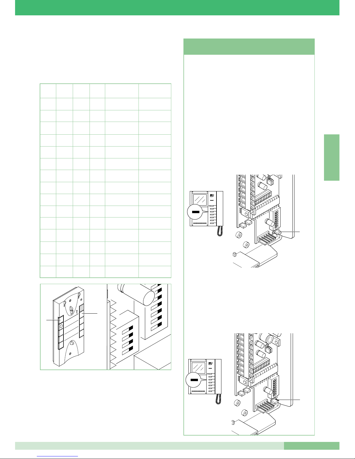
MT KIT 04
67
MT KIT 04
F R A N Ç A I S
Programmation combiné parlophonique (option) Art. 2610
Si vous décidez d’augmenter le système BRAVO KIT en ajoutant
un combiné parlophonique en option Art. 2610, veuillez trouver cidessous le tableau nécessaire pour définir les fonctions que le
combiné parlophonique devra réaliser.
DIP 1 DIP 2 DIP3 DIP 4 Fonction touche 1 Fonction touche 2
0 0 0 0
Actionneur générique
Appel au standard
1
0 0 0
Appel au standard
Inter. un
appartement
0
1
0 0
Appel au standard
Inter. deux
appartements
1 1
0 0
Actionneur générique
Inter. un
appartement
0 0
1
0
Actionneur générique
Inter. deux
appartements
1
0
1
0
Docteur Appel au standard
0
1 1
0
Docteur
Actionneur
générique
1 1 1
0
Docteur
Inter. un
appartement
0 0 0
1
Docteur
Inter. deux
appartements
1
0 0
1
Inter. un appartement
Inter. deux
appartements
0
1
0
1
Appel au standard
Auto-allumage
1 1
0
1
Actionneur générique
Auto-allumage
0 0
1 1
Docteur
Auto-allumage
1
0
1 1
Inter. un appartement
Auto-allumage
0
1 1 1
Inter. deux
appartements
Auto-allumage
2
ON
U4
4
3
1
1
3
2
5
4
7
6
9
8
P1
P2
Fonction Branchement automatique (seulement pour les
installations avec 1 ou 2 plaques de rue) sur un moniteur, avec
les brides Art. 5714/K programmées comme Principales (voir
JP1 à la figure, position P). La fonction de branchement
automatique doit être validée. Validation/Invalidation de la
fonction de branchement automatique : pour valider cette
fonction, appuyer de manière prolongée sur le bouton 2 du
moniteur (faire attention à la modalité BRAVO KIT programmé
avec les microswitches de programmation), pendant plus de 4
sec. Cette programmation est confirmée par l’émission d’une
double tonalité de validation, dans le récepteur.
Pour invalider cette fonction, appuyer sur ce même bouton
pendant plus de 4 secondes. Dans ce cas, vous entendrez une
seule tonalité de confirmation dans le récepteur.
Utilisation du branchement automatique: si cette fonction a été
validée, pour brancher le moniteur, appuyer et relâcher
immédiatement le bouton 2.
Demande vidéo sur le moniteur avec les brides Art. 5714/K
programmées comme Secondaire (voir JP1 dans la figure, à la
position S). La fonction de Demande vidéo ne requiert aucune
validation, elle permet de brancher un moniteur après un appel
venant de la plaque de rue.
Utilisation de la fonction Demande vidéo : pour brancher le
moniteur, appuyer et relâcher tout de suite le bouton 2 (faire
attention à la modalité BRAVO KIT programmée avec les
microswitches de programmation).
1 2 3
4
ON
5 6 7
8
DIP
JP1
1
2
3
4
5
6
2
Fonction Branchement Automatique
et Demande vidéo
1 2 3
4
ON
5 6 7
8
DIP
JP1
1
2
3
4
5
6
2
Page 70
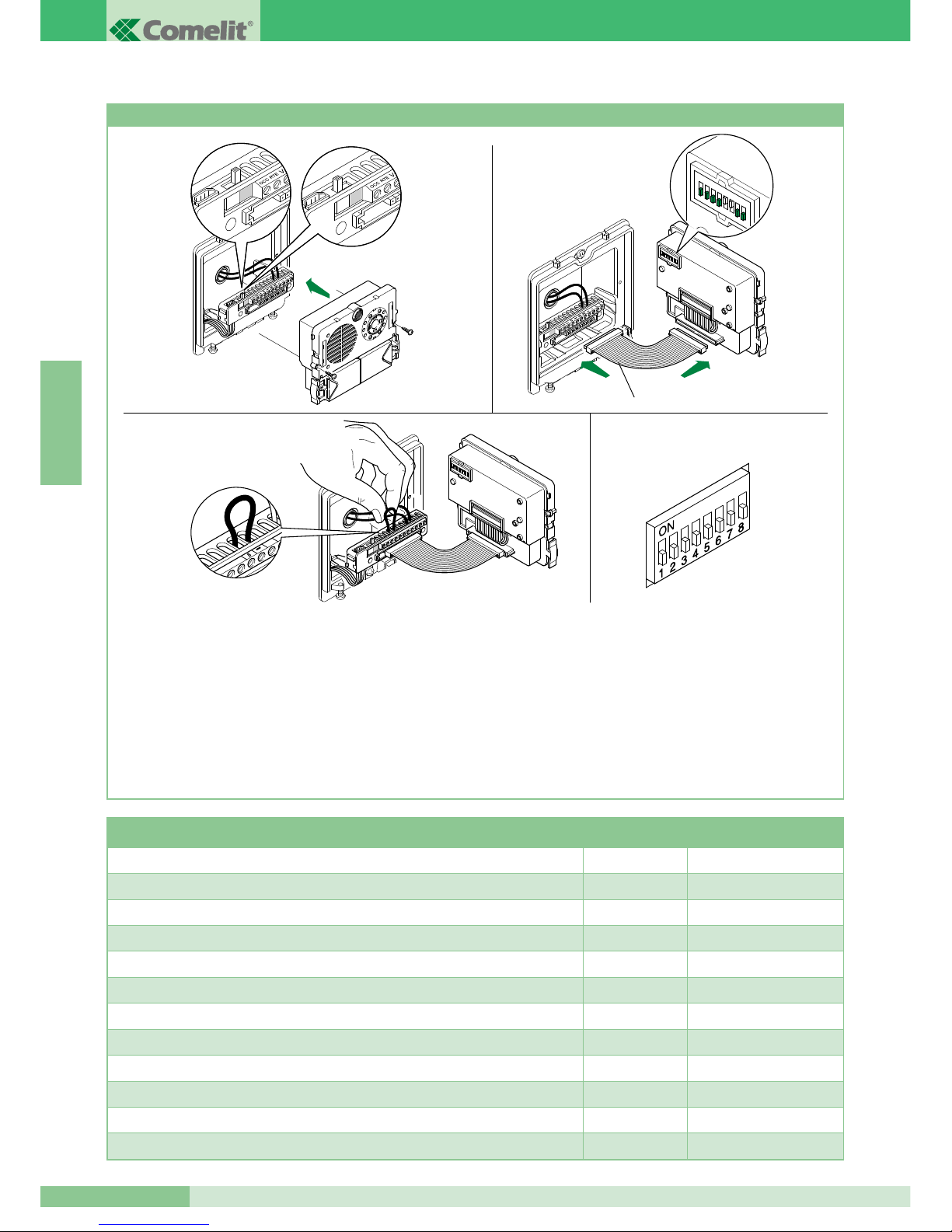
GROUP S.P.A.
MT KIT 04
68
F R A N Ç A I S
Programmations spéciales Art. 4660/BK
Sur l’Art. 4660/BK, il est possible d’effectuer une série de
programmations spéciales en fonction des différentes exigences
du système.
1. Sur le bornier des articles 4660/BK, déplacer le commutateur
en position de programmation (carré rouge) (voir fig. 1A).
2. Définir sur les microswitches de l’article (Figure 2) le code
relatif à la fonction que l’on désire programmer. Utiliser le
tableau ci-dessous pour référence.
3. Sur le bornier des articles 4660/BK, connecter la borne S avec
- (Figure 3).
4. Attendre l’émission de la tonalité de confirmation de la
programmation et enlever le cavalier entre le borne S e -.
5. À la fin de la procédure, s’assurer d’avoir bien remis le
commutateur en position de repos (carré blanc) (Figure 2A),
d’avoir enlever le cavalier entre S et - et replacer tous les
microswitches sur OFF (0) de la manière illustrée à la Figure 4.
Pour effectuer une autre programmation spéciale, répéter les
opérations décrites du point 1 au point 5.
1
2 3
4 5
6 7 8
ON
DIP
Art. 3309
Fig. 1A Fig. 2A
Fig. 1
Fig. 3
Fig. 2
Fig. 4
Microswitches sur
ON
Numéro de référence
configuration
Temps d’attente reset 10 secondes (réglage d’origine) 1,2,5,6,7,8 243
Temps d’attente reset 1 seconde 3,5,6,7,8 244
Désactivation ton confirmation gâche et programmation temps gâche 2 secondes (réglage d’usine) 1,3,5,6,7,8 245
Activation tonalité de confirmation gâche 2,3,5,6,7,8 246
Temps gâche 8 secondes 1,2,3,5,6,7,8 247
Envoi appel simple (réglage d’usine) 4,5,6,7,8 248
Envoi appel répété 3 fois 1,4,5,6,7,8 249
Commande ouvre-porte normalement ouvert (NO) (réglage d’usine) 2,4,5,6,7,8 250
Commande Ouvre-porte normalement fermé (NF) 1,2,4,5,6,7,8 251
Ouvre-porte actif également en absence d’appel (réglage d’usine) 3,4,5,6,7,8 252
Ouvre-porte validé seulement pour l’usager appelé 1,3,4,5,6,7,8 253
Restauration de tous les réglages d’usine 2,3,4,5,6,7,8 254
Page 71
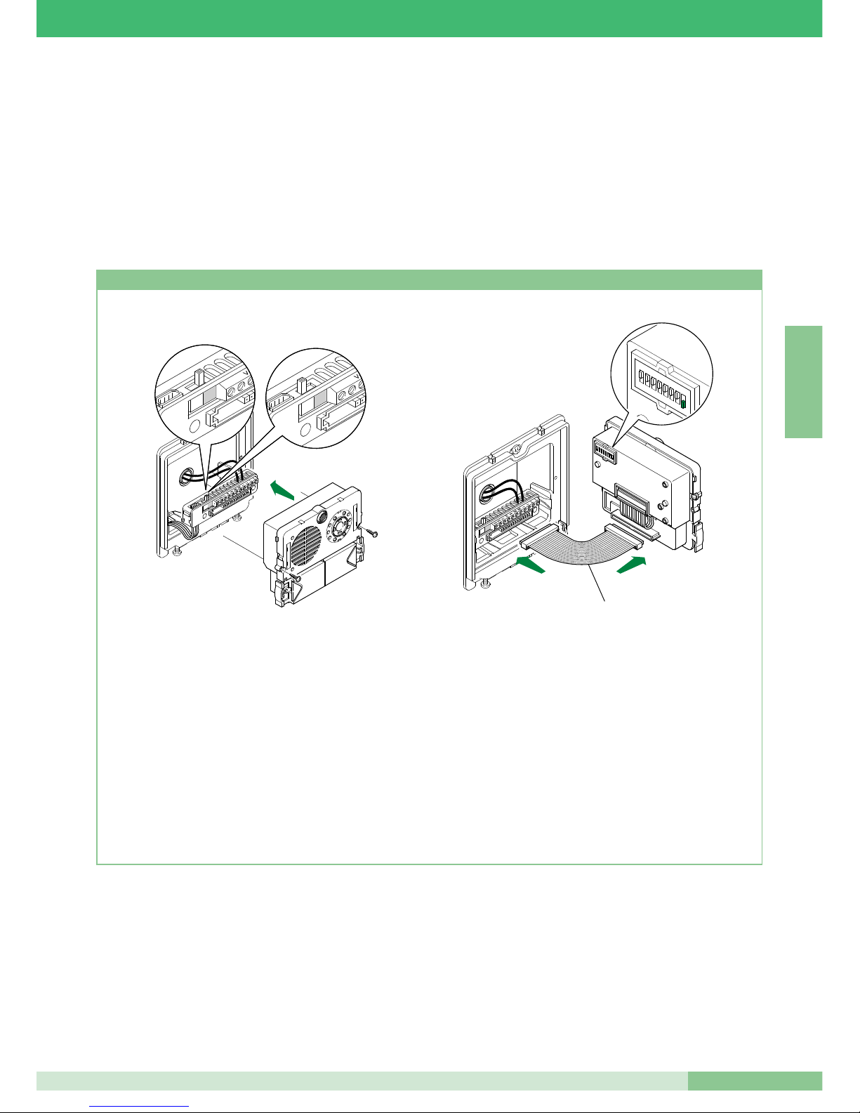
MT KIT 04
69
MT KIT 04
F R A N Ç A I S
MODULARITÉ DU SYSTÈME BRAVO KIT
boutons de l’Art. 4660/BK embarqué sur l’Art. 4875/BK ou 4876/BK
comme décrit dans la procédure suivante et les brides 5714/K avec
le code correspondant (pour la référence, voir le tableau page 63).
Pour plus de détails sur l’intégration des BRAVO KIT dans des
installations Simplebus et pour la programmation de la porte
principale (Art. 4660), se référer au catalogue Simplebus 2
(Catalogue n° 66), au manuel technique MT/SB2/01 et à la feuille
technique FT/SB/16.
Les schémas BK/EN/100 et BK/EN/101 pages 90 et 92 contenus à
la section A de ce manuel illustrent une configuration d’installation
possible, offrant la possibilité de gérer jusqu’à un maximum de 30
BRAVO KIT, par un Art. 4660 placé, par exemple, à l’entrée d’un
complexe résidentiel.
L’utilisation de ces schémas d’installation permet d’appeler un des
BRAVO KIT de la plaque de rue principale, intégrant l’Art. 4660.
Dans cette configuration, il est nécessaire de programmer les
Programmation Art. 4660/BK
1. Sur le bornier du module Art. 4660/BK, brancher l’alimentation
sur ~~ , déplacer le commutateur en position de
programmation (rouge) (voir fig. 1A).
Brancher le bornier au module Art. 4660/BK assemblé de la
manière précédemment indiquée.
NOTE: pour connecter le bornier au module Art. 4660/BK,
lors de la programmation on pourra utiliser le petit câble Art.
3309 disponible comme accessoire en option (figure 2).
2. Programmer le microswitch placé sur le dos du module audio-
vidéo avec le même code attribué au combiné parlophonique
ou au moniteur selon la correspondance décrite dans le
tableau de programmation page 63.
3. Appuyer sur le bouton que l’on désire associer à l’appel du
combiné parlophonique ou moniteur. La réalisation de la
programmation est signalée par un bip de confirmation.
4. À la fin de la programmation, remettre le commutateur en
position de standby (blanc) (voir fig. 2A).
1
2
3
4
5
6 7
8
ON
DIP
Art. 3309
Fig. 1A Fig. 2A
Fig. 1 Fig. 2
Page 72
GROUP S.P.A.
MT KIT 04
70
F R A N Ç A I S
fonctionnement, se référer aux indications page 60.
Configuration microswitches (dénommés ci-après DIP) sur la bride :
DIP 1 sur ON - DIP 2, DIP 3, DIP 4, DIP 5 sur OFF :
introduire le code usager numéro 1 pour appel depuis plaque de
rue deux appartements (4876/BK).
DIP 2 sur ON - DIP 1, DIP 3, DIP 4, DIP 5 sur OFF :
introduire le code usager numéro 2 pour appel depuis plaque de
rue deux appartements (4876/BK).
DIP 6, DIP 7, DIP 8 : selon les fonctions désirées.
JP1 en position P : définit la bride du moniteur comme principale.
Se référer au tableau des pages précédentes avec les indications
pour les programmations des configurations possibles. Au moyen d’un
échangeur Art. 1224A et d’un second poste externe Art. 4876/BK, il
est possible de compléter l’installation deux appartements avec deux
plaques de rue. On peut réaliser cette même opération avec les kits
un appartement. Dans les installations équipées de 2 Art. 4876/BK, il
est possible de visualiser alternativement l’image depuis un poste
externe ou depuis l’autre (fonction “basculer”) en appuyant sur le bouton d’auto-allumage à plusieurs reprises. Terminer le montant avec la
borne Art. 1216 comme indiqué sur le schéma. La distance maximum
entre l’Art. 1214/2 et le moniteur est de 20 mètres.
Schéma BK/03A Page 78
Connexion en cascade
Schéma base pour kit deux appartements Art. 8173.
Pour les conducteurs à utiliser et pour les distances maximums de
fonctionnement, se référer aux indications page 60.
Configuration microswitches (dénommés ci-après DIP) sur la bride :
DIP 1 sur ON - DIP 2, DIP 3, DIP 4, DIP 5 sur OFF :
introduire le code usager numéro 1 pour appel depuis plaque de
rue deux appartements (4876/BK).
DIP 2 sur ON - DIP 1, DIP 3, DIP 4, DIP 5 sur OFF :
introduire le code usager numéro 2 pour appel depuis plaque de
rue deux appartements (4876/BK).
DIP 6, DIP 7, DIP 8 : selon les fonctions désirées.
JP1 en position P : définit la bride du moniteur comme principale.
Se référer au tableau des pages précédentes avec les indications
pour les programmations des configurations possibles. Au moyen
d’un échangeur Art. 1224A et d’un second poste externe Art.
4876/BK il est possible de compléter l’installation deux appartements
avec deux plaques de rue.
On peut réaliser cette même opération avec le kit un appartement.
Dans les installations équipées de 2 Art. 4876/BK, il est possible de
visualiser alternativement l’image depuis un poste externe ou
depuis l’autre (fonction “basculer”) en appuyant sur le bouton d’auto-allumage à plusieurs reprises. Terminer le montant avec la borne
Art. 1216 comme indiqué sur le schéma.
Schéma pour kits deux appartements complétés avec
un second Art. 4876/BK, un autre moniteur secondaire
et un combiné parlophonique pour chaque appartement.
Schéma BK/04B Page 79
Connexion en dérivation
Schéma pour kits deux appartements complétés
avec un second Art. 4876/BK, un autre moniteur
principal et un combiné parlophonique pour chaque
appartement.
Schéma BK/04A Page 80
Connexion en cascade
DESCRIPTION SCHÉMAS DE CONNEXION BRAVO KIT
Schéma base pour kit un appartement Art. 8171
Schéma BK/01 Page 74
Schéma de base pour kit un appartement Art. 8171.
Pour les conducteurs à utiliser et pour les distances maximums de
fonctionnement, se référer aux indications page 60.
Configuration microswitches (dénommés ci-après DIP) sur la bride :
DIP 1 sur ON - DIP 2, DIP 3, DIP 4, DIP 5 sur OFF :
introduire le code usager numéro 1 pour appel depuis plaque de
rue un appartement (4875/BK).
DIP 6, DIP 7, DIP 8 : selon les fonctions désirées.
JP1 en position P : définit la bride du moniteur comme principale.
Se référer au tableau page 63 avec les indications pour les programmations des configurations possibles.
Schéma base pour kit deux appartements Art. 8173
Schéma BK/02B Page 75
Connexion en dérivation
Schéma base pour kit deux appartements Art. 8173.
Pour les conducteurs à utiliser et pour les distances maximums de
fonctionnement, se référer aux indications page 60.
Configuration microswitches (dénommés ci-après DIP) sur la bride :
DIP 1 sur ON - DIP 2, DIP 3, DIP 4, DIP 5 sur OFF :
introduire le code usager numéro 1 pour appel depuis plaque de
rue deux appartements (4876/BK).
DIP 2 sur ON - DIP 1, DIP 3, DIP 4, DIP 5 sur OFF :
introduire le code usager numéro 2 pour appel depuis plaque de
rue deux appartements (4876/BK).
DIP 6, DIP 7, DIP 8 : selon les fonctions désirées.
JP1 en position P : définit la bride du moniteur comme principale.
Se référer au tableau page 63 avec les indications pour les programmations des configurations possibles. Terminer le montant
avec la borne Art. 1216 comme indiqué sur le schéma. La distance
maximum entre l’Art. 1214/2 et le moniteur est de 20 mètres.
Schéma BK/02A Page 76
Connexion en cascade
Schéma base pour kit deux appartements Art. 8173.
Pour les conducteurs à utiliser et pour les distances maximums de
fonctionnement, se référer aux indications page 60.
Configuration microswitches (dénommés ci-après DIP) sur la bride :
DIP 1 sur ON - DIP 2, DIP 3, DIP 4, DIP 5 sur OFF :
introduire le code usager numéro 1 pour appel depuis plaque de
rue deux appartements (4876/BK).
DIP 2 sur ON - DIP 1, DIP 3, DIP 4, DIP 5 sur OFF :
introduire le code usager numéro 2 pour appel depuis plaque de
rue deux appartements (4876/BK).
DIP 6, DIP 7, DIP 8 : selon les fonctions désirées.
JP1 en position P : définit la bride du moniteur comme principale.
Se référer au tableau page 63 avec les indications pour les programmations des configurations possibles. Terminer le montant
avec la borne Art. 1216 comme indiqué sur le schéma.
Schéma pour kit deux appartements Art. 8173
complétés avec un second Art. 4876/BK
Schéma BK/03B Page 77
Connexion en dérivation
Schéma base pour kit deux appartements Art. 8173.
Pour les conducteurs à utiliser et pour les distances maximums de
Page 73

MT KIT 04
71
MT KIT 04
F R A N Ç A I S
face à la plaque de rue. Pour les modalités d’emploi de l’Art. 1256,
voir la feuille technique FT SB2 02 de cet article.
Adjonction actionneur Art. 1256
Schéma BK/A page 87
En insérant l’Art. 1256 en parallèle aux bornes de la bride 5714/K, il
est possible de commander le relais incorporé dans l’actionneur au
moyen des boutons dédiés sur le moniteur et/ou combiné parlophonique. Capacité relais actionneur : 10 A. Pour les modalités d’emploi
de l’Art. 1256, voir la feuille technique FT SB2 02 de cet article.
Variante pour connecter le bouton de commande de
gâche local temporisé
Schéma BK/O page 87
Connexion de dispositifs de répétition d’appel (Art.
1229 ou Art. 1122/A)
Schéma SB2/AAK page 88
La somme du nombre de postes intérieurs ayant le même code utilisateur et du nombre de dispositifs de répétition d’appel branchés à
ces postes intérieurs ne peut pas être supérieure à 4. Connecter un
seul dispositif de répétition d’appel pour chaque poste intérieur.
La distance MAX de la connexion entre le poste intérieur et le dispositif de répétition d’appel est de 20 m ; pour la connexion, utiliser un
câble blindé et ne pas faire passer les câbles à proximité de charges
inductives lourdes ou de câbles d’alimentation (230V / 400V).
En cas de connexion de charges inductives, il est conseillé d’installer
une capacité de 470nF en parallèle aux contacts C-NO de l’Art.
1122/A. En cas de perturbation audio induite par le raccordement des
fils bornes S+ S-, utiliser l’Art 1232 (voir schéma GEN/AAB page 88).
Utilisation Art. 1232 pour filtrage perturbations
induites sur les bornes S+ et S-
Schéma GEN/AAB page 88
Variant A: Adjonction bouton d’appel hors porte
page 89
On peut ajouter une borne d’appel hors porte en se reliant aux
bornes CFP et CFP de la bride 5714/K. L’appel hors porte a un ton
différent par rapport à celui de la plaque de rue.
En cas de plusieurs combinés ou brides avec le même code utilisateur, relier le bouton CFP sur un seul ; tous les dispositifs sonneront
en même temps.
Emploi bouton 1 pour usages divers
Schéma BK/P page 89
Variante pour utilisation borne LED 1
Schéma BK/N page 89
Schéma pour connexion à porte principale de 3
BRAVO KIT avec Art. 4834/9
Schéma BK/EN/100 page 90
Schéma de connexion à porte principale avec
standard Art. 1998A (option) de 30 BRAVO KIT
(maximum).
Dérivation Bravo Kit de 1214/2
Schéma BK/EN/101 page 92
Schéma pour kit un appartement avec alimentateur
complémentaire Art. 1395
Schéma BK/01A page 81
DESCRIPTION VARIANTES DE CONNEXION BRAVO KIT
Utilisation module caméra déportée Art. 1259/A
Schéma BK/05 pagé 82
Connexion amplificateur vidéo Art. 4833/A
Schéma SB2/AAQ page 83
Adjonction d’un moniteur principal en parallèle
Schéma BK/H page 83
Connexion en cascade
Il est possible d’agrandir l’installation de base jusqu’à un maximum
de trois usagers internes pour chaque bouton d’appel de la plaque
de rue. Pour ajouter un moniteur, il faut avoir les Art. 5714/K (bride),
5701 (moniteur) et le transformateur d’alimentation Art. 1212/B.
Programmer les DIP avec le code usager selon le tableau page 63.
Câbler les deux brides en les reliant en cascade entre-sort (voir
schéma) ou utiliser les bornes 1214/2 pour se dériver du montant
(voir schéma BK/I page 84).
Schéma BK/I page 84
Connexion en dérivation
Connexion en cascade d’un moniteur principal et
d’un moniteur secondaire avec le même code usager
Schéma BK/C page 84
Dans ce schéma, on voit la possibilité de relier deux moniteurs
(principal et secondaire) en cascade entre eux et dérivés du montant avec l’Art. 1214/2. Dans cette configuration, sur appel depuis la
plaque de rue, on aura l’allumage du moniteur principal et la possibilité d’allumer le moniteur secondaire en appuyant sur le bouton 2
(auto-allumage/demande vidéo) Sur appel de la plaque de rue, la
sonnerie s’active sur les deux moniteurs.
Adjonction d’un combiné parlophonique en parallèle
en dérivation du montant
Schéma BK/D page 85
Connexion combinés parlophoniques supplémentaires en dérivation du moniteur
Schéma BK/AAB page 85
Connexion combinés parlophoniques supplémentaires en cascade du moniteur
Schéma BK/AAA page 86
Adjonction pilotage éclairage extérieur par Art. 1256
Schéma BK/E page 86
En insérant l’Art.1256 en parallèle aux bornes LL de la bride
5714/K, on peut obtenir le consentement pour piloter une lampe
externe synchrone à l’allumage du moniteur
De cette manière, tant sur appel que sur la commande d’auto-allumage, il est possible d’éclairer de manière optimale le sujet situé
Page 74
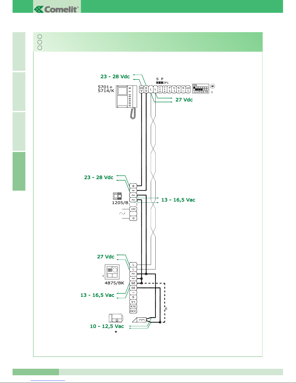
GROUP S.P.A.
MT KIT 04
72
I T A L I A N OE N G L I S HF R A N Ç A I SA
*
Durante l’attivazione
*
When switching on
*
Durant l'activation
Messa in funzione/verifica tensioni di impianto a riposo
Switching on/voltage check with system at rest
Mise en service/vérification tensions d’installation au repos
IT
EN
FR
Page 75
MT KIT 04
73
MT KIT 04
A
I T A L I A N OE N G L I S H
F R A N Ç A I S
BRAVO KIT VIDEO
VIDEO BRAVO KIT
VIDEO BRAVO KIT
IT SCHEMI DI COLLEGAMENTO
EN CONNECTION DIAGRAMS
FR SCHÉMAS DE BRANCHEMENT
IT VARIANTI DI COLLEGAMENTO
EN VARIANTIONS OF SYSTEM DIAGRAMS
FR VARIANTES DE CONNEXION
•
BK/01
74
•
BK/02B
75
•
BK/02A
76
•
BK/03B
77
•
BK/03A
78
•
BK/04B
79
•
BK/04A
80
•
BK/01A
81
•
BK/05
82
•
SB2/AAQ
83
•
BK/H
83
•
BK/I
84
•
BK/C
84
•
BK/D
85
•
BK/AAB
85
•
BK/AAA
86
•
BK/E
86
•
BK/A
87
•
BK/O
87
•
SB2/AAK
88
•
GEN/AAB
88
•
VARIANTE A
89
VARIANT A
•
BK/P
89
•
BK/N
89
•
BK/EN/100
90
•
BK/EN/101
92
Page 76
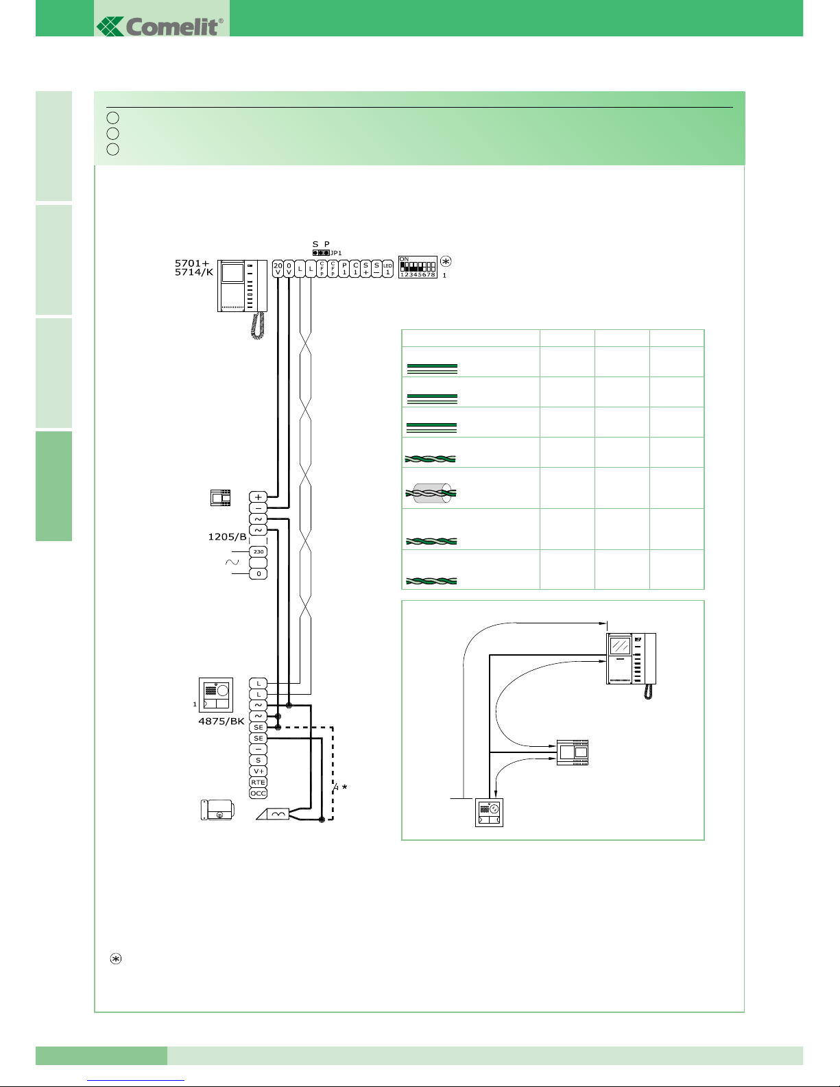
GROUP S.P.A.
MT KIT 04
74
I T A L I A N OE N G L I S HF R A N Ç A I SA
N.B. Le impostazioni di S1-6, S1-7 e S1-8 sono in funzione della configurazione desiderata (vedi tabella a pag 16).
NOTE: The S1-6, S1-7 and S1-8 settings depend on the configuration required (see table on page 40).
NOTE: Les programmations de S1-6, S1-7 et S1-8 sont en fonction de la configuration désirée (voir tableau page 64).
Schema base per kit monofamiliari Art. 8171.
Basic wiring diagram for single-family kits Art. 8171.
Schéma base pour kit un appartement Art. 8171.
BK/01
*
Pulsante comando apriporta locale
*
Door-release button
*
Bouton commande ouvre-porte local
4875/BK
4876/BK
1205/B
A
B
C
150 m
(495 feet)
150 m
(495 feet)
100 m
(325 feet)
150 m
(495 feet)
A (max) B (max) C (max)
0,5 mm2(Ø 0,8 mm - Ø 8/10 AWG 20)
1 mm2(Ø 1,2 mm - Ø 12/10 AWG 17)
1,5 mm2(Ø 1,4 mm - Ø 14/10 AWG 15)
20 m
(65 feet)
25 m
(85 feet)
0,28 mm2(Ø 0,6 mm - Ø 6/10 AWG 23)
1 mm2(Ø 1,2 mm - Ø 12/10 AWG 17)
40 m
(130 feet)
60 m
(195 feet)
50 m
(165 feet)
100 m
(325 feet)
UTP5 Cat 5
0,2 mm2(Ø 0,5 mm - Ø 5/10 AWG 24)
150 m
(495 feet)
150 m
(495 feet)
150 m
(495 feet)
Comelit Art. 4576 / Art. 4578
0,5 mm
2
(Ø 0,8 mm - Ø 8/10 AWG 20)
Per maggiori informazioni sulle distanze vedi pagina 12 e 13.
For further information about distances refer to pages 36 and 37.
Pour plus de détails sur les distances faire référence au pages 60 et 61.
IT
EN
FR
Page 77
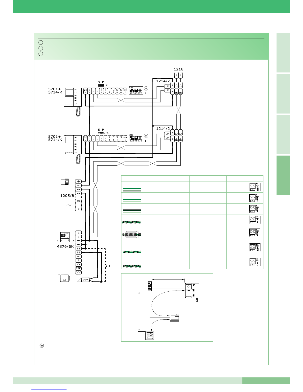
MT KIT 04
75
MT KIT 04
A
I T A L I A N OE N G L I S H
F R A N Ç A I S
N.B. Le impostazioni di S1-6, S1-7 e S1-8 sono in funzione della configurazione desiderata (vedi tabella a pag 16).
NOTE: The S1-6, S1-7 and S1-8 settings depend on the configuration required (see table on page 40).
NOTE: Les programmations de S1-6, S1-7 et S1-8 sont en fonction de la configuration désirée (voir tableau page 64).
Schema base per kit bifamiliari Art. 8173 con collegamento in derivazione.
Basic wiring diagram for two-family kits Art. 8173 with branched connection.
Schéma base pour kit deux appartements Art. 8173 avec connexion en dérivation.
BK/02B
Art. 1216
2
2
1
1
1
40 m
(130 feet)
40 m
(130 feet)
20 m
(65 feet)
40 m
(130 feet)
D (max)
40 m
(130 feet)
50 m
(165 feet)
40 m
(130 feet)
Per maggiori informazioni
sulle distanze vedi pagina
12 e 13.
For further information
about distances refer to
pages 36 and 37.
Pour plus de détails sur
les distances faire référence
au pages 60 et 61.
*
Pulsante comando apriporta locale
*
Door-release button
*
Bouton commande ouvre-porte local
150 m
(495 feet)
150 m
(495 feet)
100 m
(325 feet)
150 m
(495 feet)
A (max) B (max) C (max)
0,5 mm2(Ø 0,8 mm - Ø 8/10 AWG 20)
1 mm2(Ø 1,2 mm - Ø 12/10 AWG 17)
1,5 mm2(Ø 1,4 mm - Ø 14/10 AWG 15)
20 m
(65 feet)
25 m
(85 feet)
0,28 mm2(Ø 0,6 mm - Ø 6/10 AWG 23)
1 mm2(Ø 1,2 mm - Ø 12/10 AWG 17)
40 m
(130 feet)
60 m
(195 feet)
50 m
(165 feet)
100 m
(325 feet)
UTP5 Cat 5
0,2 mm2(Ø 0,5 mm - Ø 5/10 AWG 24)
150 m
(495 feet)
150 m
(495 feet)
150 m
(495 feet)
Comelit Art. 4576 / Art. 4578
0,5 mm
2
(Ø 0,8 mm - Ø 8/10 AWG 20)
4875/BK
4876/BK
1205/B
1214/2
1216
C
A
B
D
IT
EN
FR
Page 78
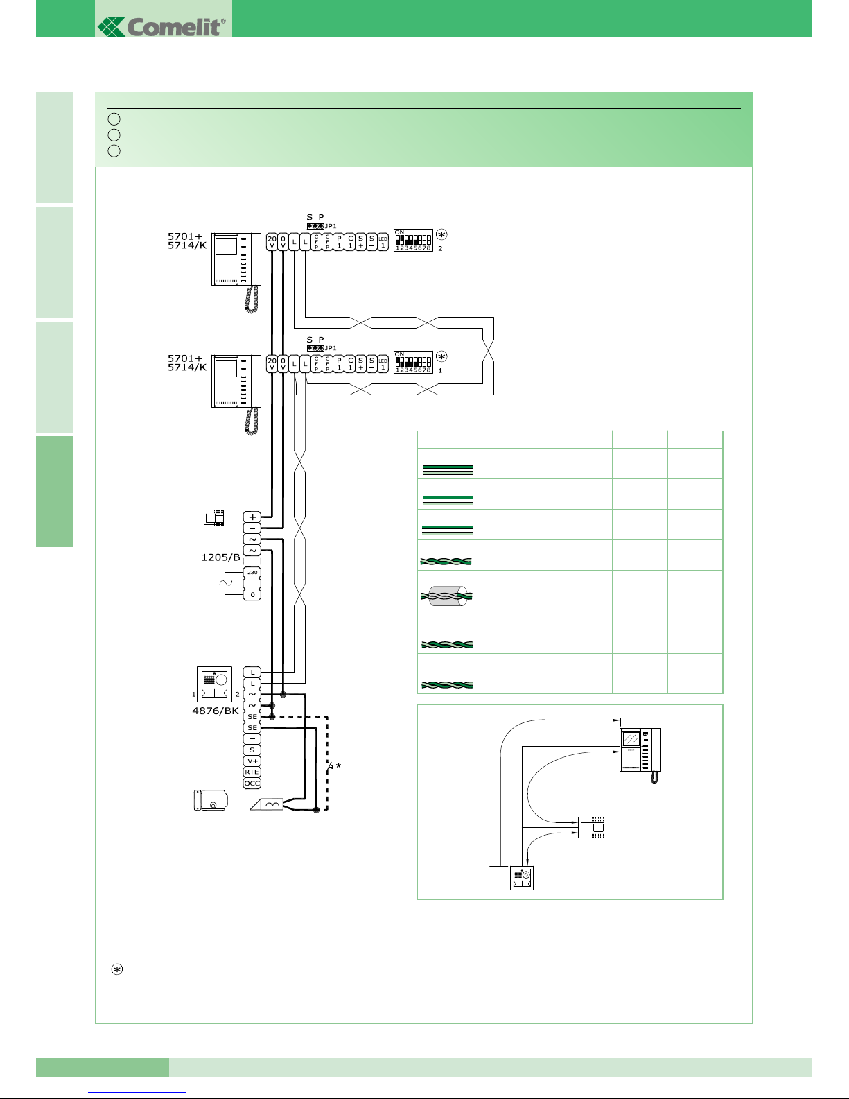
GROUP S.P.A.
MT KIT 04
76
I T A L I A N OE N G L I S HF R A N Ç A I SA
N.B. Le impostazioni di S1-6, S1-7 e S1-8 sono in funzione della configurazione desiderata (vedi tabella a pag 16).
NOTE: The S1-6, S1-7 and S1-8 settings depend on the configuration required (see table on page 40).
NOTE: Les programmations de S1-6, S1-7 et S1-8 sont en fonction de la configuration désirée (voir tableau page 64).
Schema base per kit bifamiliari Art. 8173 con collegamento in cascata.
Basic wiring diagram for two-family kits Art. 8173 with connection in cascade.
Schéma base pour kit deux appartements Art. 8173 avec connexion en cascade.
BK/02A
*
Pulsante comando apriporta locale
*
Door-release button
*
Bouton commande ouvre-porte local
4875/BK
4876/BK
1205/B
A
B
C
150 m
(495 feet)
150 m
(495 feet)
100 m
(325 feet)
150 m
(495 feet)
A (max) B (max) C (max)
0,5 mm2(Ø 0,8 mm - Ø 8/10 AWG 20)
1 mm2(Ø 1,2 mm - Ø 12/10 AWG 17)
1,5 mm2(Ø 1,4 mm - Ø 14/10 AWG 15)
20 m
(65 feet)
25 m
(85 feet)
0,28 mm2(Ø 0,6 mm - Ø 6/10 AWG 23)
1 mm2(Ø 1,2 mm - Ø 12/10 AWG 17)
40 m
(130 feet)
60 m
(195 feet)
50 m
(165 feet)
100 m
(325 feet)
UTP5 Cat 5
0,2 mm2(Ø 0,5 mm - Ø 5/10 AWG 24)
150 m
(495 feet)
150 m
(495 feet)
150 m
(495 feet)
Comelit Art. 4576 / Art. 4578
0,5 mm
2
(Ø 0,8 mm - Ø 8/10 AWG 20)
Per maggiori informazioni sulle distanze vedi pagina 12 e 13.
For further information about distances refer to pages 36 and 37.
Pour plus de détails sur les distances faire référence au pages 60 et 61.
IT
EN
FR
Page 79
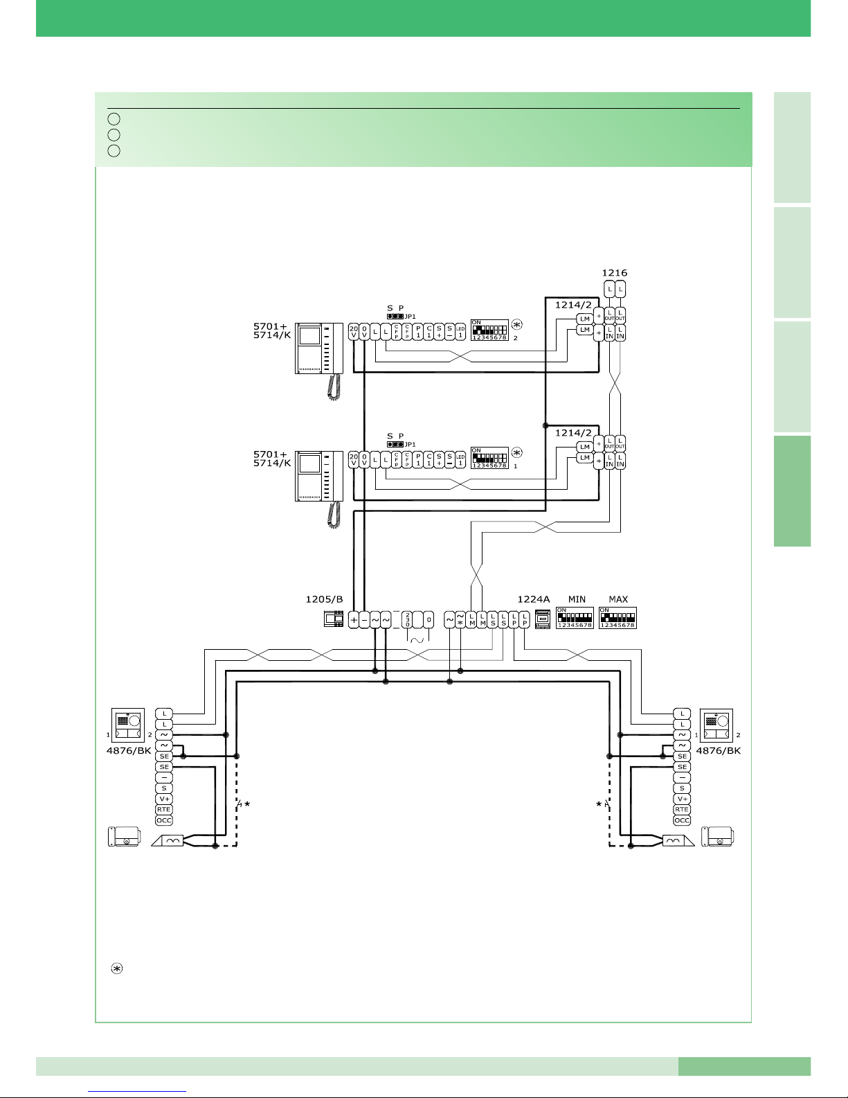
MT KIT 04
77
MT KIT 04
A
I T A L I A N OE N G L I S H
F R A N Ç A I S
N.B. Le impostazioni di S1-6, S1-7 e S1-8 sono in funzione della configurazione desiderata (vedi tabella a pag 16).
NOTE: The S1-6, S1-7 and S1-8 settings depend on the configuration required (see table on page 40).
NOTE: Les programmations de S1-6, S1-7 et S1-8 sont en fonction de la configuration désirée (voir tableau page 64).
Schema per kit bifamiliari Art. 8173 ampliati con un secondo Art. 4876/BK. Collegamento in derivazione.
Wiring diagram for two-family kit Art. 8173 expanded with a second Art. 4876/BK. Branched connection.
Schéma pour kit deux appartements Art. 8173 complétés avec un second Art. 4876/BK. Connexion en dérivation.
BK/03B
*
Pulsante comando apriporta locale
*
Door-release button
*
Bouton commande ouvre-porte local
IT
EN
FR
Page 80

GROUP S.P.A.
MT KIT 04
78
I T A L I A N OE N G L I S HF R A N Ç A I SA
N.B. Le impostazioni di S1-6, S1-7 e S1-8 sono in funzione della configurazione desiderata (vedi tabella a pag 16).
NOTE: The S1-6, S1-7 and S1-8 settings depend on the configuration required (see table on page 40).
NOTE: Les programmations de S1-6, S1-7 et S1-8 sont en fonction de la configuration désirée (voir tableau page 64).
Schema per kit bifamiliari Art. 8173 ampliati con un secondo Art. 4876/BK. Collegamento in cascata.
Basic wiring diagram for two-family kit Art. 8173 expanded with a second Art. 4876/BK. Cascade connection.
Schéma pour kit deux appartements Art. 8173 avec un second Art. 4876/BK. Connexion en cascade.
BK/03A
*
Pulsante comando apriporta locale
*
Door-release button
*
Bouton commande ouvre-porte local
IT
EN
FR
Page 81
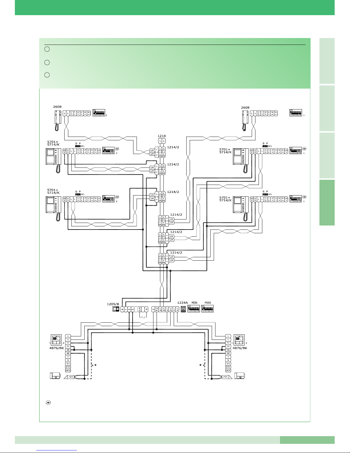
MT KIT 04
79
MT KIT 04
A
I T A L I A N OE N G L I S H
F R A N Ç A I S
N.B. Le impostazioni di S1-6, S1-7 e S1-8 sono in funzione della configurazione desiderata (vedi tabella a pag 16).
NOTE: The S1-6, S1-7 and S1-8 settings depend on the configuration required (see table on page 40).
NOTE: Les programmations de S1-6, S1-7 et S1-8 sont en fonction de la configuration désirée (voir tableau page 64).
Schema per kit bifamiliari ampliati con un secondo Art. 4876/BK, un’ulteriore monitor secondario e un citofono per ciascuna
unità familiare. Collegamento in derivazione.
Wiring diagram for two-family kit expanded with a second Art. 4876/BK, an additional secondary monitor and a telephone
for each family unit. Branched connection.
Schéma pour kits deux appartements complétés avec un second Art. 4876/BK, un autre moniteur secondaire et un combiné
parlophonique pour chaque appartement. Connexion en derivation.
BK/04B
*
Pulsante comando apriporta locale
*
Door-release button
*
Bouton commande ouvre-porte local
IT
EN
FR
Page 82
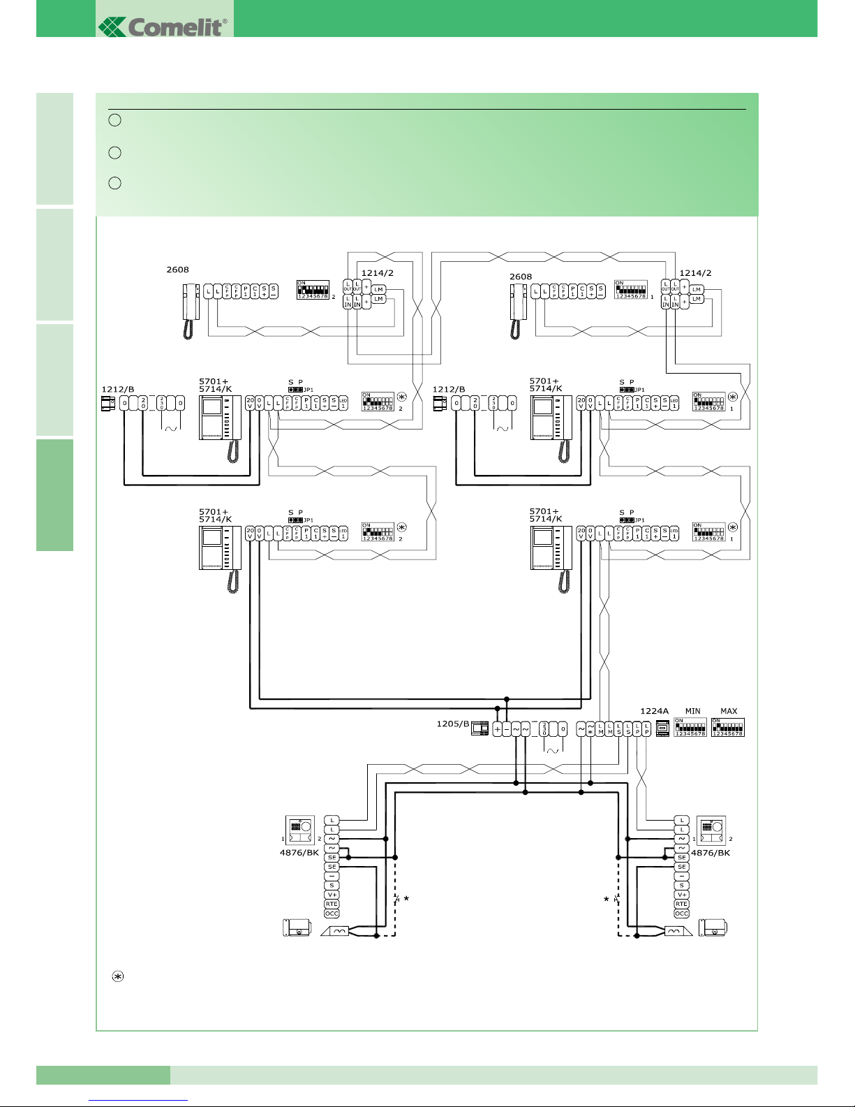
GROUP S.P.A.
MT KIT 04
80
I T A L I A N OE N G L I S HF R A N Ç A I SA
N.B. Le impostazioni di S1-6, S1-7 e S1-8 sono in funzione della configurazione desiderata (vedi tabella a pag 16).
NOTE: The S1-6, S1-7 and S1-8 settings depend on the configuration required (see table on page 40).
NOTE: Les programmations de S1-6, S1-7 et S1-8 sont en fonction de la configuration désirée (voir tableau page 64).
*
Pulsante comando apriporta locale
*
Door-release button
*
Bouton commande ouvre-porte local
Schema per kit bifamiliari ampliati con un secondo Art. 4876/BK, un’ulteriore monitor principale e un citofono per ciascuna
unita’ familiare. Collegamento in cascata.
Wiring diagram for two-family kit expanded with a second Art. 4876/BK, an additional main monitor and a telephone for
each family unit. Cascade connection.
Schéma pour kit deux appartements complétés avec un second Art. 4876/BK, un autre moniteur principal et un combiné
parlophonique pour chaque appartement. Connexion en cascade.
BK/04A
IT
EN
FR
Page 83
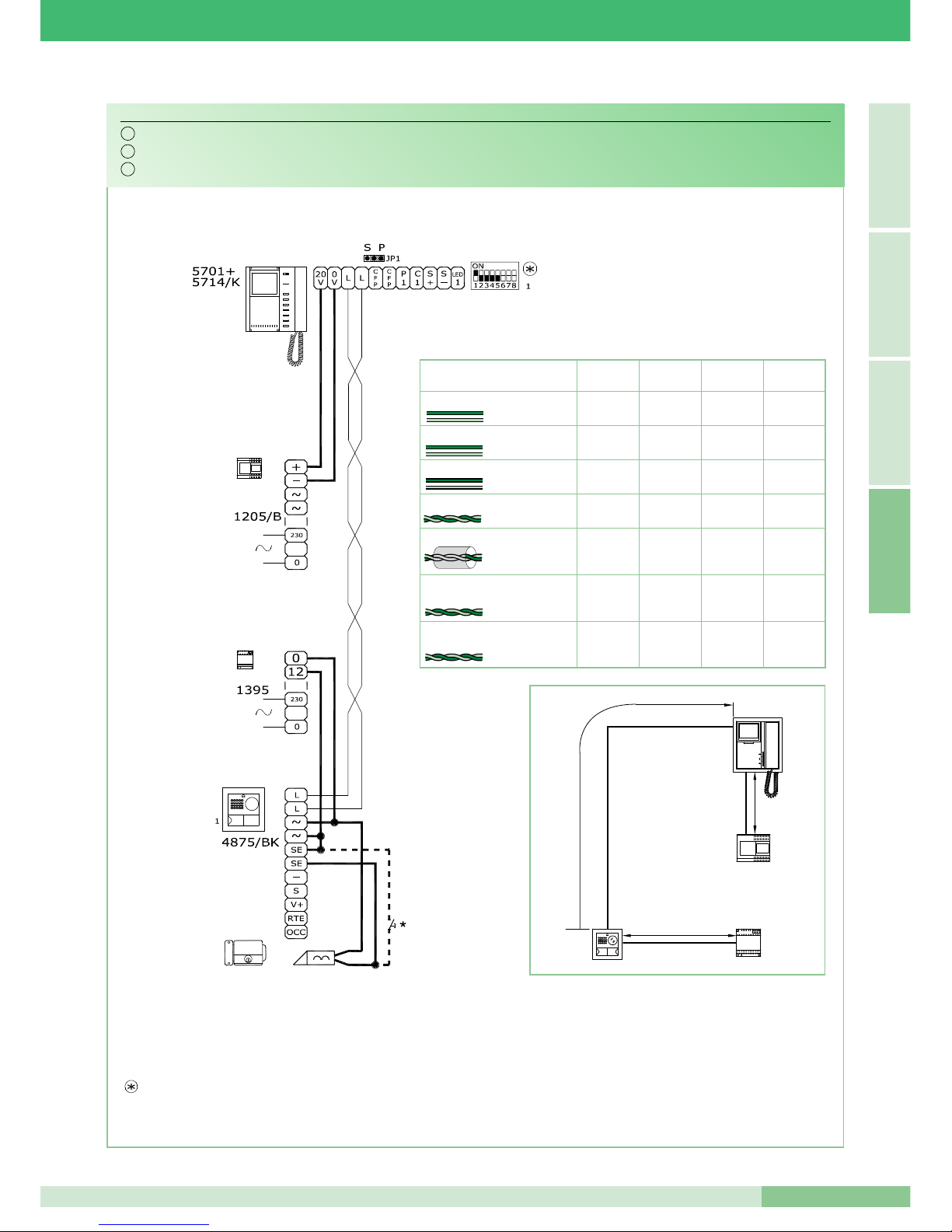
MT KIT 04
81
MT KIT 04
A
I T A L I A N OE N G L I S H
F R A N Ç A I S
N.B. Le impostazioni di S1-6, S1-7 e S1-8 sono in funzione della configurazione desiderata (vedi tabella a pag 16).
NOTE: The S1-6, S1-7 and S1-8 settings depend on the configuration required (see table on page 40).
NOTE: Les programmations de S1-6, S1-7 et S1-8 sont en fonction de la configuration désirée (voir tableau page 64).
Schema per kit monofamiliare con alimentatore aggiuntivo Art. 1395.
Diagram for single-family kit with additional power feeder Art. 1395.
Schéma pour kit un appartement avec alimentateur complémentaire Art. 1395.
BK/01A
150 m
(495 feet)
150 m
(495 feet)
100 m
(325 feet)
150 m
(495 feet)
A (max) B (max) C (max)
0,5 mm2(Ø 0,8 mm - Ø 8/10 AWG 20)
1 mm2(Ø 1,2 mm - Ø 12/10 AWG 17)
1,5 mm2(Ø 1,4 mm - Ø 14/10 AWG 15)
20 m
(65 feet)
25 m
(85 feet)
0,28 mm2(Ø 0,6 mm - Ø 6/10 AWG 23)
1 mm2(Ø 1,2 mm - Ø 12/10 AWG 17)
40 m
(130 feet)
60 m
(195 feet)
50 m
(165 feet)
100 m
(325 feet)
UTP5 Cat 5
0,2 mm2(Ø 0,5 mm - Ø 5/10 AWG 24)
150 m
(495 feet)
150 m
(495 feet)
150 m
(495 feet)
300 m
(990 feet)
300 m
(990 feet)
200 m
(650 feet)
300 m
(990 feet)
C (max) con
Art. 4833/A
300 m
(990 feet)
300 m
(990 feet)
300 m
(990 feet)
Comelit Art. 4576 / Art. 4578
0,5 mm
2
(Ø 0,8 mm - Ø 8/10 AWG 20)
Per maggiori informazioni sulle distanze vedi pagina 12 e 13.
For further information about distances refer to pages 36 and 37.
Pour plus de détails sur les distances faire référence au pages 60 et 61.
*
Pulsante comando apriporta locale
*
Door-release button
*
Bouton commande ouvre-porte local
1205/B
A
B
C
1395
4875/BK
4876/BK
IT
EN
FR
Page 84
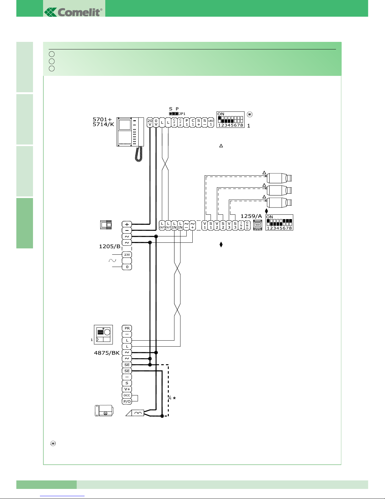
GROUP S.P.A.
MT KIT 04
82
I T A L I A N OE N G L I S HF R A N Ç A I SA
N.B. Le impostazioni di S1-6, S1-7 e S1-8 sono in funzione della configurazione desiderata (vedi tabella a pag 16).
NOTE: The S1-6, S1-7 and S1-8 settings depend on the configuration required (see table on page 40).
NOTE: Les programmations de S1-6, S1-7 et S1-8 sont en fonction de la configuration désirée (voir tableau page 64).
*
Pulsante comando apriporta locale
*
Door-release button
*
Bouton commande ouvre-porte local
Da alimentare separatamente
To be powered separately
À alimenter séparément
Per settaggio e funzionamento Art. 1259/A vedi FT/SB/13.
For setting and operation Art. 1259/A see FT/SB/13.
Pour programmation et fonctionnement Art. 1259/A voir FT/SB/13.
Utilizzo modulo telecamera scorporata Art. 1259/A.
Use of remote camera module Art. 1259/A.
Utilisation module caméra déportée Art. 1259/A.
BK/05
IT
EN
FR
Page 85
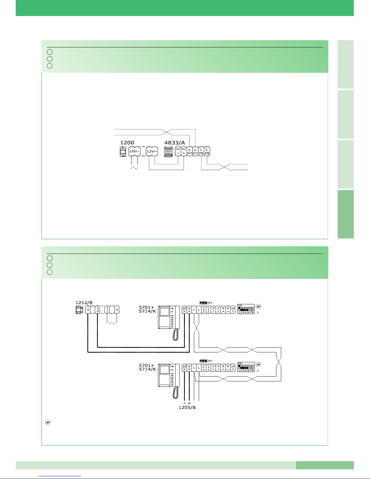
S P
S P
MT KIT 04
83
MT KIT 04
A
I T A L I A N OE N G L I S H
F R A N Ç A I S
N.B. I due posti interni devono avere lo stesso indirizzo utente. Le impostazioni di S1-6, S1-7 e S1-8 sono in funzione della configurazione desiderata (vedi tabella a pag 16).
NOTE: The two internal units must have the same user address. The S1-6, S1-7 and S1-8 settings depend on the configuration required (see table on page 40).
NOTE: Les deux postes internes doivent avoir la même adresse utilisateur. Les programmations de S1-6, S1-7 et S1-8 sont en fonction de la configuration désirée (voir tableau page 64).
Aggiunta di un monitor principale in parallelo, collegamento in cascata.
Addition of main monitor in parallel connection in cascade.
Adjonction d’un moniteur principal en parallèle. Connexion en cascade.
BK/H
LINEA MONTANTE
LINE RISER
LIGNE MONTANT
DAL POSTO ESTERNO
FROM EXTERNAL UNIT
DEPUIS LA PLAQUE DE RUE
Collegamento amplificatore video Art. 4833/A.
Connection of video amplifier Art. 4833/A.
Connexion amplificateur vidéo Art. 4833/A.
SB2/AAQ
IT
EN
FR
IT
EN
FR
Page 86
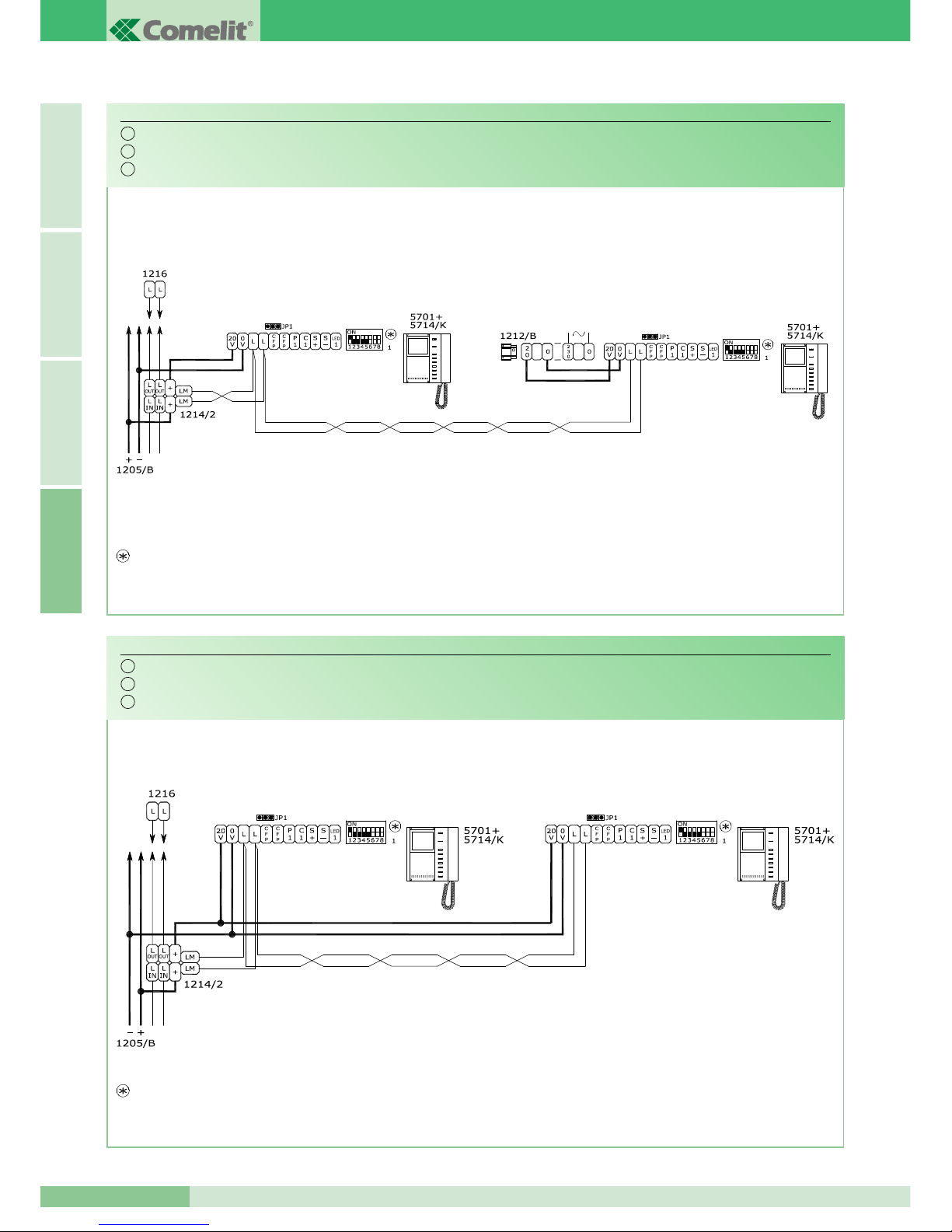
S P
S P
S P S P
GROUP S.P.A.
MT KIT 04
84
I T A L I A N OE N G L I S HF R A N Ç A I SA
Aggiunta di un monitor principale in parallelo, collegamento in derivazione.
Addition of a main monitor in parallel, with branched connection.
Adjonction d’un moniteur principal en parallèle. Connexion en dérivation.
BK/I
MONITOR PRINCIPALE
MAIN MONITOR
MONITEUR PRINCIPAL
MONITOR PRINCIPALE
MAIN MONITOR
MONITEUR PRINCIPAL
Collegamento in cascata di un monitor principale e di un monitor secondario con lo stesso codice utente.
Connection in cascade of a main monitor and a secondary monitor with the same user code.
Connexion en cascade d’un moniteur principal et d’un moniteur secondaire avec le même code usager.
BK/C
MONITOR PRINCIPALE
MAIN MONITOR
MONITEUR PRINCIPAL
MONITOR SECONDARIO
SECONDARY MONITOR
MONITEUR SECONDAIRE
N.B. I due posti interni devono avere lo stesso indirizzo utente. Le impostazioni di S1-6, S1-7 e S1-8 sono in funzione della configurazione desiderata (vedi tabella a pag 16).
NOTE: The two internal units must have the same user address. The S1-6, S1-7 and S1-8 settings depend on the configuration required (see table on page 40).
NOTE: Les deux postes internes doivent avoir la même adresse utilisateur. Les programmations de S1-6, S1-7 et S1-8 sont en fonction de la configuration désirée (voir tableau page 64).
N.B. I due posti interni devono avere lo stesso indirizzo utente. Le impostazioni di S1-6, S1-7 e S1-8 sono in funzione della configurazione desiderata (vedi tabella a pag 16).
NOTE: The two internal units must have the same user address. The S1-6, S1-7 and S1-8 settings depend on the configuration required (see table on page 40).
NOTE: Les deux postes internes doivent avoir la même adresse utilisateur. Les programmations de S1-6, S1-7 et S1-8 sont en fonction de la configuration désirée (voir tableau page 64).
IT
EN
FR
IT
EN
FR
Page 87
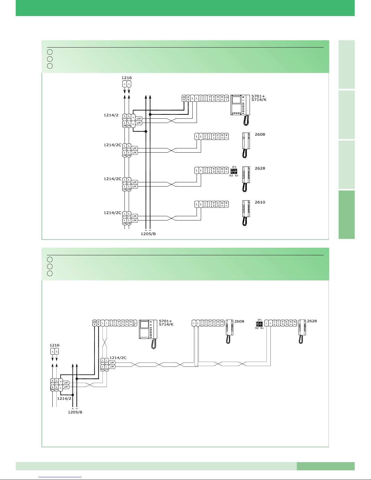
MT KIT 04
85
MT KIT 04
A
I T A L I A N OE N G L I S H
F R A N Ç A I S
Aggiunta di un citofono in parallelo in derivazione dal montante.
Addition of a parallel telephone. Branch connection from riser.
Adjonction d’un combiné parlophonique en parallèle en dérivation du montant.
BK/D
Collegamento citofoni aggiuntivi in derivazione dal monitor.
Connection of additional telephones, branch connection from monitor.
Connexion combinés parlophoniques supplémentaires en dérivation du moniteur.
BK/AAB
IT
EN
FR
IT
EN
FR
Page 88
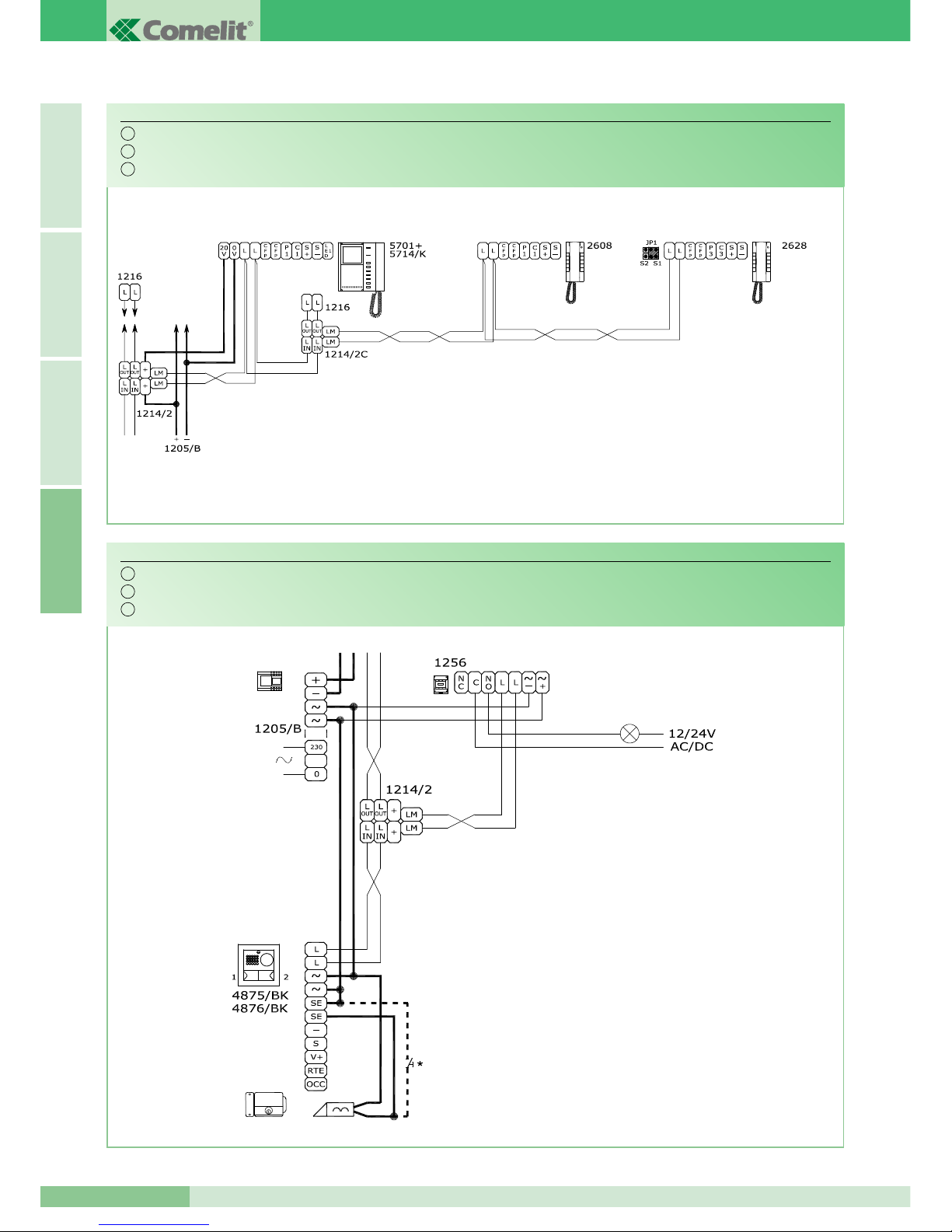
GROUP S.P.A.
MT KIT 04
86
I T A L I A N OE N G L I S HF R A N Ç A I SA
Collegamento citofoni aggiuntivi in cascata dal monitor.
Connection of additional telephones, connection in cascade from monitor.
Connexion combinés parlophoniques supplémentaires en cascade du moniteur.
BK/AAA
*
Pulsante comando apriporta locale
*
Door-release button
*
Bouton commande ouvre-porte local
Per settaggio funzioni A,C,D,E dell'Art. 1256, vedi FT/SB2/02.
For setting of functions A,C,D,E of Art. 1256, see FT/SB2/02.
Pour programmation des fonctions A,C,D,E de l'Art. 1256,
voir FT/SB2/02.
Aggiunta pilotaggio luce esterna tramite Art. 1256.
Addition of external light control using of Art. 1256.
Adjonction pilotage éclairage extérieur par Art. 1256.
BK/E
IT
EN
FR
IT
EN
FR
Page 89
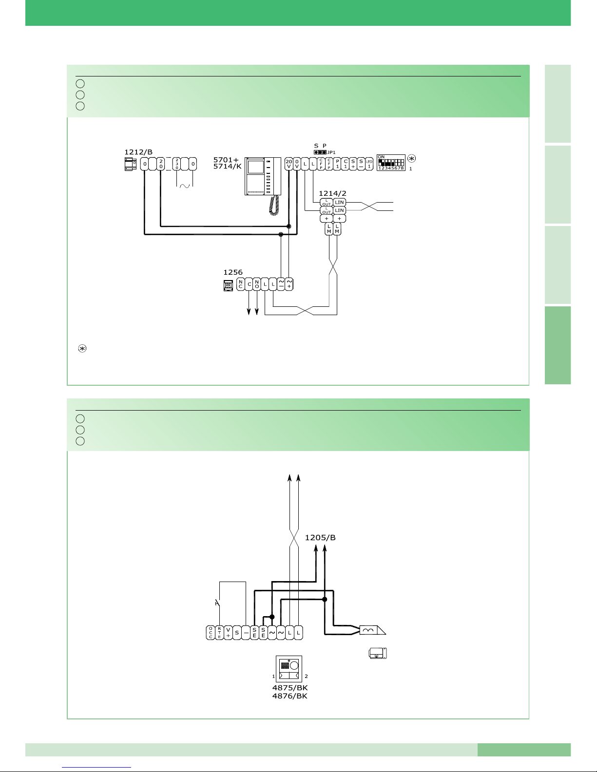
MT KIT 04
87
MT KIT 04
A
I T A L I A N OE N G L I S H
F R A N Ç A I S
N.B. Le impostazioni di S1-6, S1-7 e S1-8 sono in funzione della configurazione desiderata (vedi tabella a pag 16).
NOTE: The S1-6, S1-7 and S1-8 settings depend on the configuration required (see table on page 40).
NOTE: Les programmations de S1-6, S1-7 et S1-8 sont en fonction de la configuration désirée (voir tableau page 64).
Aggiunta attuatore Art. 1256.
Addition of actuator Art. 1256.
Adjonction actionneur Art. 1256.
BK/A
Variante collegamento apriporta locale temporizzato.
Timed local door lock release connection variant.
Variante pour connecter le bouton de commande de gâche local temporisé.
BK/O
Per settaggio funzioni A,C,D,E dell'Art. 1256, vedi FT/SB2/02.
For setting of functions A,C,D,E of Art. 1256, see FT/SB2/02.
Pour programmation des fonctions A,C,D,E de l'Art. 1256,
voir FT/SB2/02.
IT
EN
FR
IT
EN
FR
Page 90
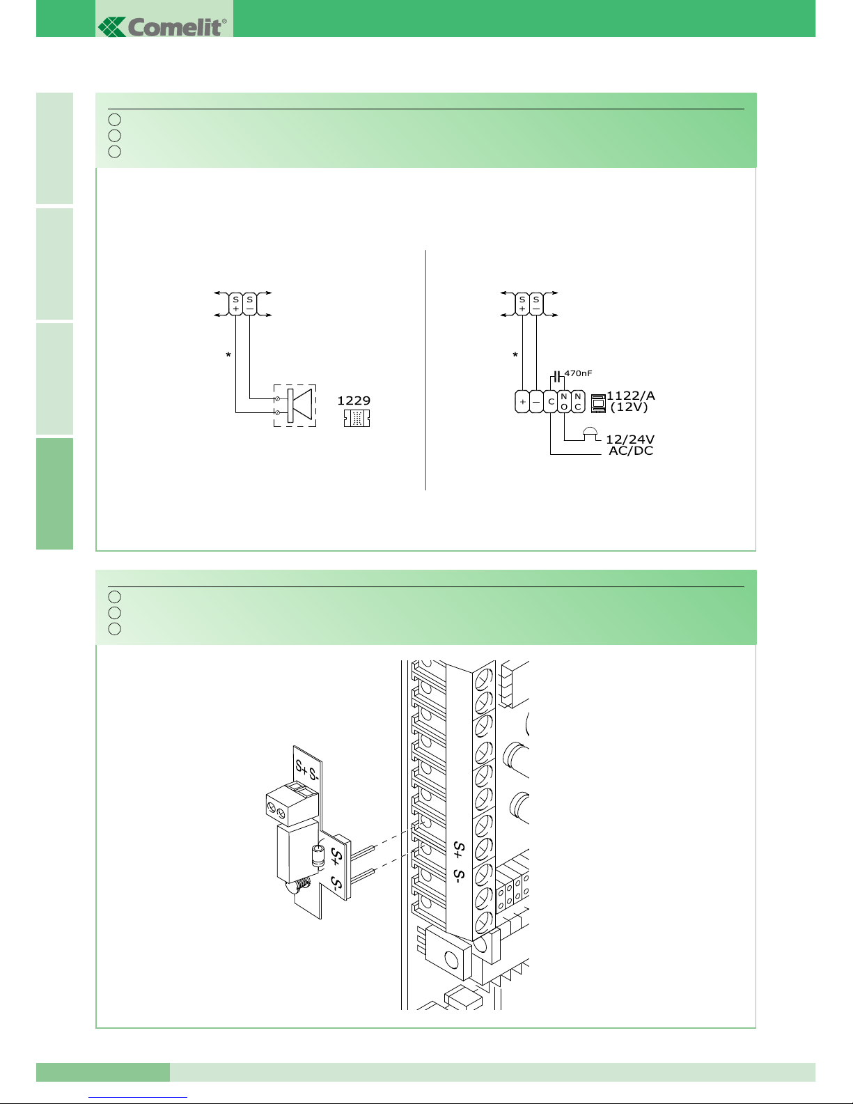
GROUP S.P.A.
MT KIT 04
88
I T A L I A N OE N G L I S HF R A N Ç A I SA
Connessione di dispositivi di ripetizione di chiamata (Art. 1229 o Art. 1122/A).
Connection of call repetition devices (Art. 1229 or Art. 1122/A).
Connexion de dispositifs de répétition d'appel (Art. 1229 ou Art. 1122/A).
SB2/AAK
vedi descrizione pag. 23.
see description page 47.
voir description page 71.
*
20m MAX
Cablaggio valido per staffa 5714/K e citofoni Art. 2608, 2628, 2610.
Wiring valid for bracket 5714/K and telephones Art. 2608, 2628, 2610.
Cablage valable pour bride 5714/K et combinès parlophoniques Art. 2608, 2628, 2610.
Utilizzo Art. 1232 per filtraggio disturbi indotti sui morsetti S+ e S-.
Use of Art. 1232 for filter induced interference on terminals S+ and S-.
Utilisation Art. 1232 pour filtrage perturbations induites sur les bornes S+ et S-.
GEN/AAB
IT
EN
FR
IT
EN
FR
Page 91

MT KIT 04
89
MT KIT 04
A
I T A L I A N OE N G L I S H
F R A N Ç A I S
Utilizzo pulsante 1 per usi vari.
Use of pushbutton 1 for various purposes.
Emploi bouton 1 pour usages divers.
BK/P
N.B. Le impostazioni di S1-6, S1-7 e S1-8 sono in funzione della configurazione desiderata (vedi tabella a pag 16).
NOTE: The S1-6, S1-7 and S1-8 settings depend on the configuration required (see table on page 40).
NOTE: Les programmations de S1-6, S1-7 et S1-8 sont en fonction de la configuration désirée (voir tableau page 64).
Aggiunta pulsante di chiamata fuori porta.
Addition of floor door call pushbutton.
Adjonction bouton d'appel hors porte.
In caso di più citofoni o staffe con lo stesso codice utente,
collegare il pulsante CFP su uno solo; tutti i dispositivi
suoneranno contemporaneamente.
If there are a number of entry phones or brackets with the
same user code connect the CFP pushbutton to one only;
all the devices will ring simultaneously.
En cas de plusieurs combinés parlophoniques ou étriers
avec le même code utilisateur, relier le bouton CFP sur un
seul ; tous les dispositifs sonneront en même temps.
VARIANTE A - VARIANT A
N.B. Le impostazioni di S1-6, S1-7 e S1-8 sono in funzione della configurazione desiderata (vedi tabella a pag 16).
NOTE: The S1-6, S1-7 and S1-8 settings depend on the configuration required (see table on page 40).
NOTE: Les programmations de S1-6, S1-7 et S1-8 sont en fonction de la configuration désirée (voir tableau page 64).
In presenza di tensione sul morsetto LED 1
il led di segnalazione lampeggia.
The signalling LED flashes in the presence
of voltage on terminal LED 1.
En prèsence de tension sur le borne LED 1
la led de signalisation clignote.
Variante per utilizzo Morsetto LED 1.
Use of LED 1 terminal.
Utilisation du borne LED 1.
BK/N
IT
EN
FR
IT
EN
FR
IT
EN
FR
Page 92

GROUP S.P.A.
MT KIT 04
90
I T A L I A N OE N G L I S HF R A N Ç A I SA
Schema per connessione a porta principale di 3 BRAVO KIT tramite Art. 4834/9.
Diagram for connecting 3 BRAVO KITS to main entrance panel by means of Art. 4834/9.
Schéma pour connexion à porte principale de 3 BRAVO KIT avec l’Art. 4834/9.
BK/EN/100
Per maggiori informazioni sulle distanze di utilizzo dell'Art. 4833/A e Art. 4834/9 e per maggiori informazioni
sulle impostazioni necessarie in merito all'Art. 1224A fare riferimento al manuale tecnico MT/SB2/01.
For further information about the usage distances of Art. 4833/A and Art. 4834/9 and for further information
about the settings needed regarding Art. 1224A, refer to the MT/SB2/01 technical manual.
Pour plus de détails sur les distances d’utilisation de l'Art. 4833/A et de l'Art. 4834/9, ainsi que pour plus de
détails sur les réglages nécessaires par rapport à l'Art. 1224A, faire référence au manuel technique MT/SB2/01.
N.B. Le impostazioni di S1-6, S1-7 e S1-8 sono in funzione della configurazione desiderata (vedi tabella a pag 16).
NOTE: The S1-6, S1-7 and S1-8 settings depend on the configuration required (see table on page 40).
NOTE: Les programmations de S1-6, S1-7 et S1-8 sont en fonction de la configuration désirée (voir tableau page 64).
Soluzione utilizzabile al massimo per 9 Bravo Kit.
Solution which can be used for a maximum of 9 Bravo Kits.
Solution utilisable au maximum pour 9 BRAVO KIT.
IT
EN
FR
Page 93
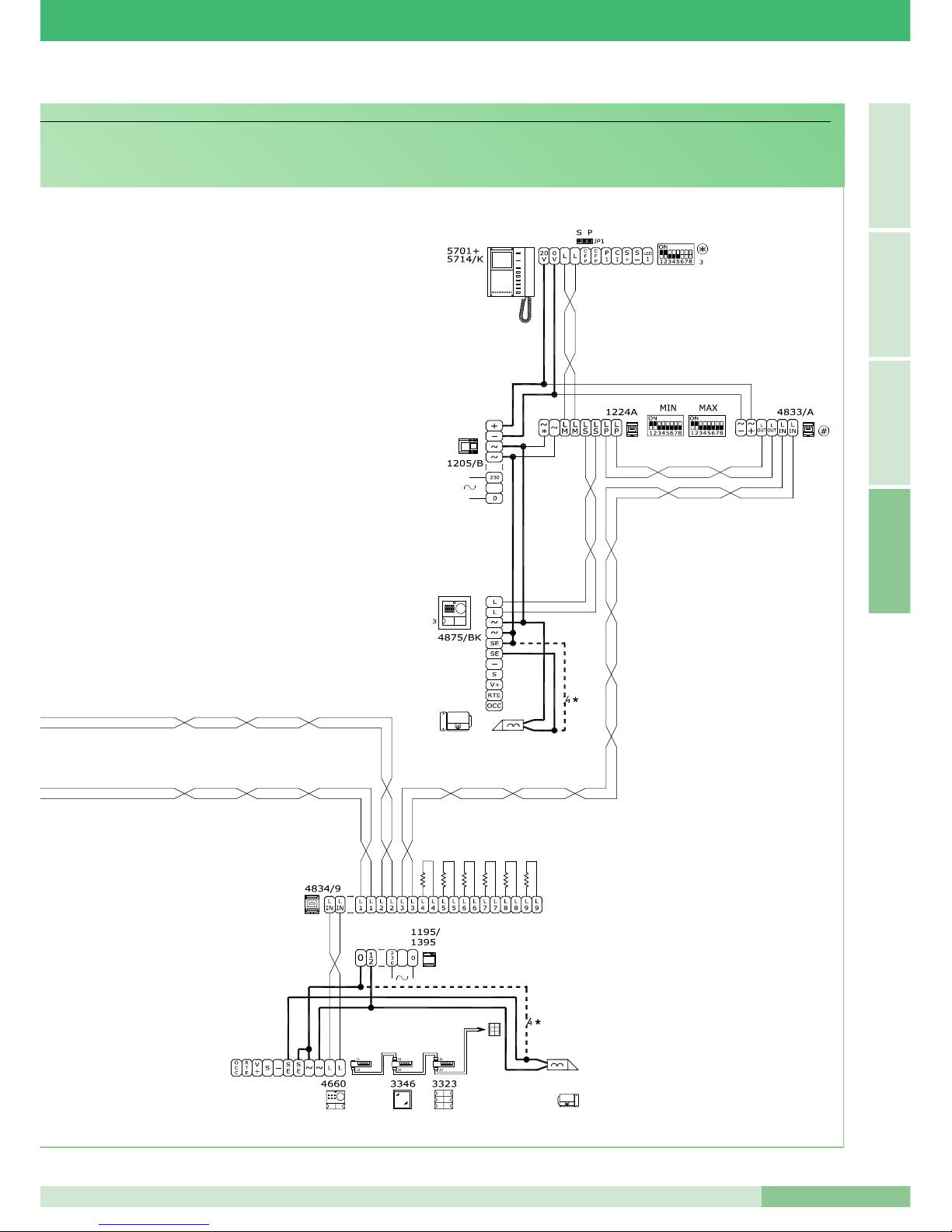
MT KIT 04
91
MT KIT 04
A
I T A L I A N OE N G L I S H
F R A N Ç A I S
*
Pulsante comando apriporta locale
*
Door-release button
*
Bouton commande ouvre-porte local
Page 94
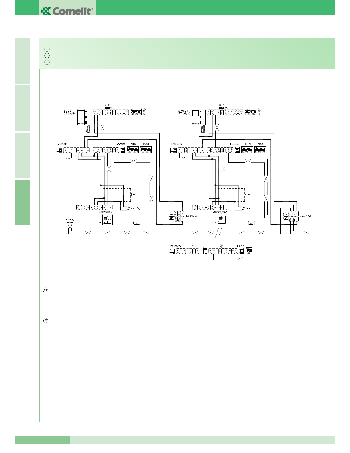
GROUP S.P.A.
MT KIT 04
92
I T A L I A N OE N G L I S HF R A N Ç A I SA
Schema di connessione a porta principale con centralino Art. 1998A (opzionale) di 30 BRAVO KIT (massimo). Derivazione Bravo Kit da 1214/2.
Wiring diagram of a main door connection with porter switchboard Art. 1998A (optional) with 30 BRAVO KITS (maximum). Bravo Kit branch from 1214/2.
Schema de connexion a la plaque de rue principale avec standard Art. 1998A (en option) de 30 BRAVO KIT (maximum). Dérivation Bravo Kit de 1214/2.
BK/EN/101
L'Art. 1236 va utilizzato in impianti cablati in questa
configurazione con più di 16 kit (Art. 8171 e Art. 8173)
derivati. L'Art. 1236 va posto in prossimità dell'uscita
Lout-Lout del morsetto Art. 1214/2 relativo al kit posto
a metà impianto.
Esempio:
- in impianti con 18 derivati posizionare l'Art. 1236
dopo il nono morsetto Art. 1214/2.
- in impianti con 23 derivati posizionare l'Art. 1236
dopo il dodicesimo morsetto Art. 1214/2.
- in impianti con 30 derivati posizionare l'Art. 1236
dopo il quindicesimo morsetto Art. 1214/2.
Per maggiori informazioni sull'utilizzo dell'Art. 1236
consultare la documentazione tecnica allegata al prodotto.
Per maggiori informazioni sulla distanza massima tra
Art. 1214/2 e il monitor più lontano vedi la tabella
riportata a pagina 12. Per maggiori informazioni in
merito alle impostazioni necessarie per l'Art. 1224A
fare riferimento al manuale tecnico MT/SB2/01.
Art. 1236 must be used in systems cabled in this
configuration with more than 16 kits (Art. 8171 and Art.
8173) branched off. Art. 1236 must be placed near the
Lout-Lout output of terminal Art. 1214/2 relative to the
kit placed half-way through the system.
Example:
- in systems with 18 branches, position Art. 1236 after
the ninth terminal Art. 1214/2.
- in systems with 23 branches, position Art. 1236 after
the tenth terminal Art. 1214/2.
- in systems with 30 branches, position Art. 1236 after
the fifteenth terminal Art. 1214/2.
For further information on the use of Art. 1236, consult
the technical documentation enclosed with the product.
For further information on the maximum distance
between Art. 1214/2 and the monitor furthest away,
see the table given on page 36. For further information
regarding the settings required for Art. 1224A, refer to
the MT/SB2/01 technical manual.
L'Art. 1236 s’utilise dans des installations câblées
ayant cette configuration avec plus de 16 kits (Art.
8171 et Art. 8173) dériv és. Placer l'Art. 1236 à
proximité de la sortie Lout-Lout de la borne Art. 1214/2
relative au kit placé au milieu de l’installation.
Par exemple:
- dans des installations avec 18 dérivés, placer l'Art.
1236 après la neuvième borne Art. 1214/2.
- dans des installations avec 23 dérivés, placer l'Art.
1236 après la douzième borne Art. 1214/2.
- dans des installations avec 30 dérivés, placer l'Art.
1236 après la quinzième borne Art. 1214/2.
Pour plus de détails sur l’utilisation de l’Art. 1236, voir
la documentation technique annexée au produit.
Pour plus de détails sur la distance maximum entre
l’Art. 1214/2 et le moniteur le plus éloigné, voir le
tableau illustré à la page 60. Pour plus de détails sur
les réglages nécessaires pour l'Art. 1224A, faire
référence au manuel technique MT/SB2/01.
N.B. Le impostazioni di S1-6, S1-7 e S1-8 sono in funzione della configurazione desiderata (vedi tabella a pag 16).
NOTE: The S1-6, S1-7 and S1-8 settings depend on the configuration required (see table on page 40).
NOTE: Les programmations de S1-6, S1-7 et S1-8 sont en fonction de la configuration désirée (voir tableau page 64).
IT
EN
FR
Page 95
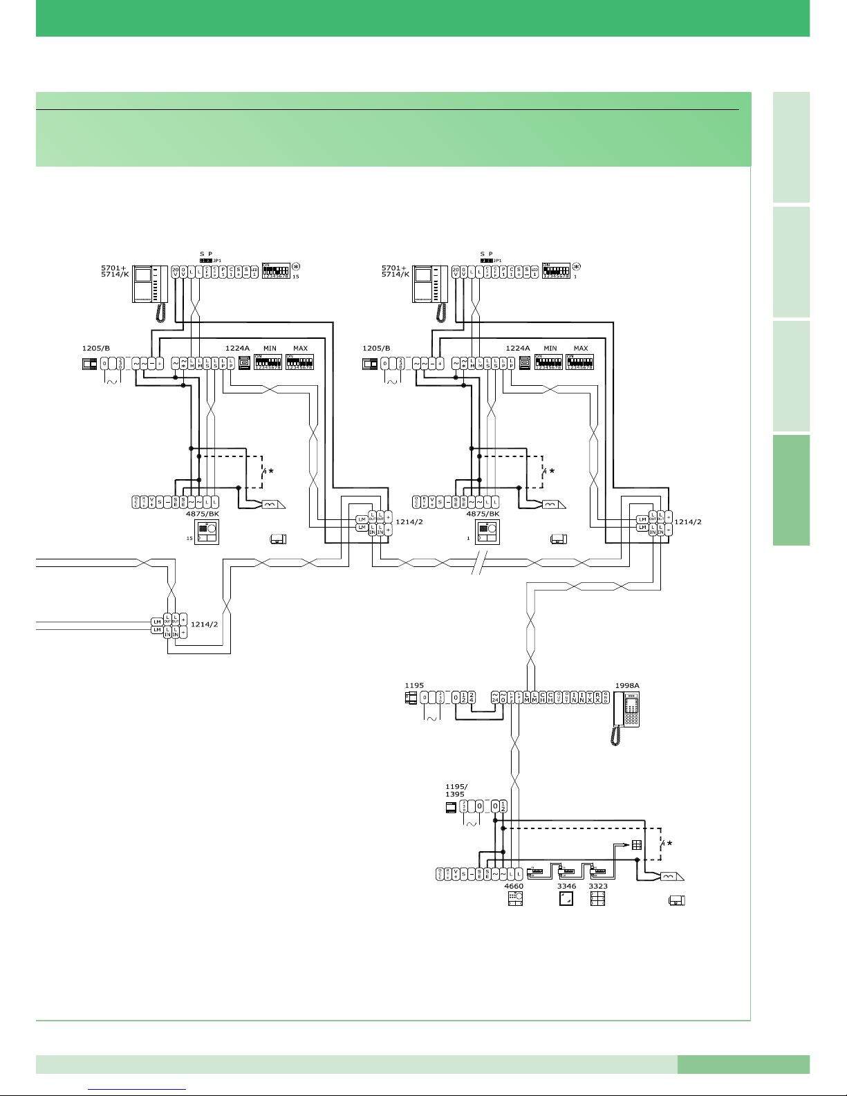
MT KIT 04
93
MT KIT 04
A
I T A L I A N OE N G L I S H
F R A N Ç A I S
*
Pulsante comando apriporta locale
*
Door-release button
*
Bouton commande ouvre-porte local
Page 96

Assistenza tecnica Italia 0346/750090 Technical service abroad (+39) 0346750092
Commerciale Italia 0346/750091 Export department (+39) 0346750093
Comelit Hellas
9 Epiru str.
16452 Argyroupolis - Athens Greece
Tel. +30 210 9968605-6 Fax : +30 210 9945560
www.comelit.gr
[email protected]
Comelit (Shanghai) Electronics Co.,Ltd
5 Floor No. 4 Building No.30 Hongcao Road
Hi-Tech Park Caohejing, Shanghai, China
Tel. +86-21-64519192/9737/3527
Fax. +86-21-64517710
www.comelit.com.cn
[email protected]
Comelit Group Belgium
Z.3 Doornveld 170
1731 Zellik ( Asse)
Tel. +32 (0) 24115099 Fax +32 (0) 24115097
www.comelit.be - [email protected]
Comelit Piemonte
Str. Del Pascolo 6/E - 10156 Torino
Tel. e Fax +39 011 2979330
www.comelit.eu
[email protected]
[email protected]
[email protected]
Comelit Group
Singapore Representative Office
54 Genting Lane, Ruby Land Complex
Blk 2, #06-01 - Singapore 349562
Tel. +65-6748 8563 - Fax +65-6748 8584
offi[email protected]
[ F ]
Comelit Group Germany GmbH
Brusseler Allee 23- 41812 Erkelenz
Tel. +49 (0) 243190151-23
+49 (0) 243190151-24
Fax +49 (0) 24319015125
www.comelit.de - [email protected]
Comelit Sud S.r.l.
Via Corso Claudio, 18
84083 Castel San Giorgio (Sa)
Tel. +39 081 516 2021
Fax +39 081 953 5951
www.comelit.eu- [email protected]
Comelit Group U.A.E.
Middle East Office
P.O. Box 54433 - Dubai U.A.E.
Tel. +971 4 299 7533 - Fax +971 4 299 7534
www.scame.ae
[email protected]
Comelit Espana S.L.
Josef Estivill 67/69 - 08027 Barcelona
Tel. +34 932 430 376 - Fax +34 934 084 683
www.comelit.es
[email protected]
Comelit Ireland
Suite 3 Herbert Hall
16 Herbert Street - Dublin 2
Tel. +353 (0) 1 619 0204
Fax. +353 (0) 1 619 0298
www.comelit.ie
[email protected]
Comelit Group UK Ltd
Unit 4 Mallow Park - Watchmead Welwyn
Garden City Herts - AL7 1GX
Tel: +44 (0)1707377203
Fax: +44 (0)1707377204
www.comelitgroup.co.uk
[email protected]
Comelit Immotec
15, Rue Jean Zay - 69800 SAINT PRIEST
Tél. +33 (0) 4 72 28 06 56 - Fax +33 (0) 4 72 28 83 29
www.comelit.fr - [email protected]
Comelit Nederland BV
Aventurijn 220-3316 LB Dordrecht
Tel. +31 (0) 786511201 - Fax +31 (0) 786170955
www.comelit.nl - [email protected]
Comelit Cyrex
250 W. Duarte Rd. Suite B
Monrovia, CA 91016
Tel. +1 626 930 0388 - Fax +1 626 930 0488
www.comelitusa.com
[email protected]
[ B ]
[ UK ]
[ NL ]
[ RC ]
[ UAE ]
[ SG ]
[ E ]
[ I ]
[ I ]
[ IRL ]
[ USA ]
[ D ]
[ GR ]
MT/KIT/04 - 3
a
edizione 03/2009 - cod. 22590200CU
8 0 2 3 9 0 3 1 9 0 1 1 3
 Loading...