

Page 1

VA NDA L RESISTA NT
BA CK-LIT WEATHERPROOF
DIGITA L ACCESS CONTROL KEYPAD
DC6 0 SS, DC5 0 SS & DC5 0 FS
Program m ing & Inst allat io n M anual
FOR ELECTRIC LOCK, INTER-LOCK
AND SECURITY SYSTEM INSTALLATIONS
APPENDIX
DRYCONTACT
A dry contact means that no electricityis connected toit. It ispreparedfor free connections. TheRelay Output
contacts provided inthiskeypad system are dry contacts.
N.C.
NormallyClosed, the contact is closed circuit at normal status. It is open circuit whenactive.
N.O.
NormallyOpen, the contact isopen circuit at normal status. It is closed circuit when active.
TRANSISTOROPENCOLLECTOR OUTPUT
An open collector output is equivalent to aNormally Open (N.O.) contact referring to ground similar to arelay
contact referring toground. Thetransistor is normally OFF, andits output switches toground (-) whenactive.
The open collector can only provide switching function for small power but it is usually good enough for
controllingof an alarm system. TheDuress, Inter-lockandKey Active Outputs of the keypadareopencollector
outputs.
OPENCOLLECTOR
OUTPUT---Output switchesto
groundwhen activates
N.O. CONTACT
OUTPUT---Output switches to
ground when activates
EQUIVALENT
VERSION: 11/09
Page 2

INTRODUCTION
DC60SS / DC50SS / DC50FS are dual relayoutput, vandalresistant and weatherproof keypads. They are employing the
durable back-lit metal key buttons and rugged metal housing for high traffic and harshenvironment.
The DC60SS is in thesize of fitting to the electric single gang box. It canbe surface mount withits aluminum housing
or flush mount on wall.
The DC50SS isin the size of fitting forgooseneck mounting. It is also suitable for surface mount or post mount on wall
with itssteel box.
The DC50FS is the flush mount versionof theDC50SS. It is designed for flush mounting on any brick or wooden wall
with itsback box.
CONNECTION TERMINALS OF THE ELECTRONIC MODULES OF THE KEYPADS
2 19
FIXINGHOLES
FORHOLLOW WOODEN
WALL MOUNTING
FIXINGHOLES
FORSOLID
WALL MOUNTING
MAGNETFOR
TAMPERSWITCH
FIXINGHOLES
FORFACEPLATE
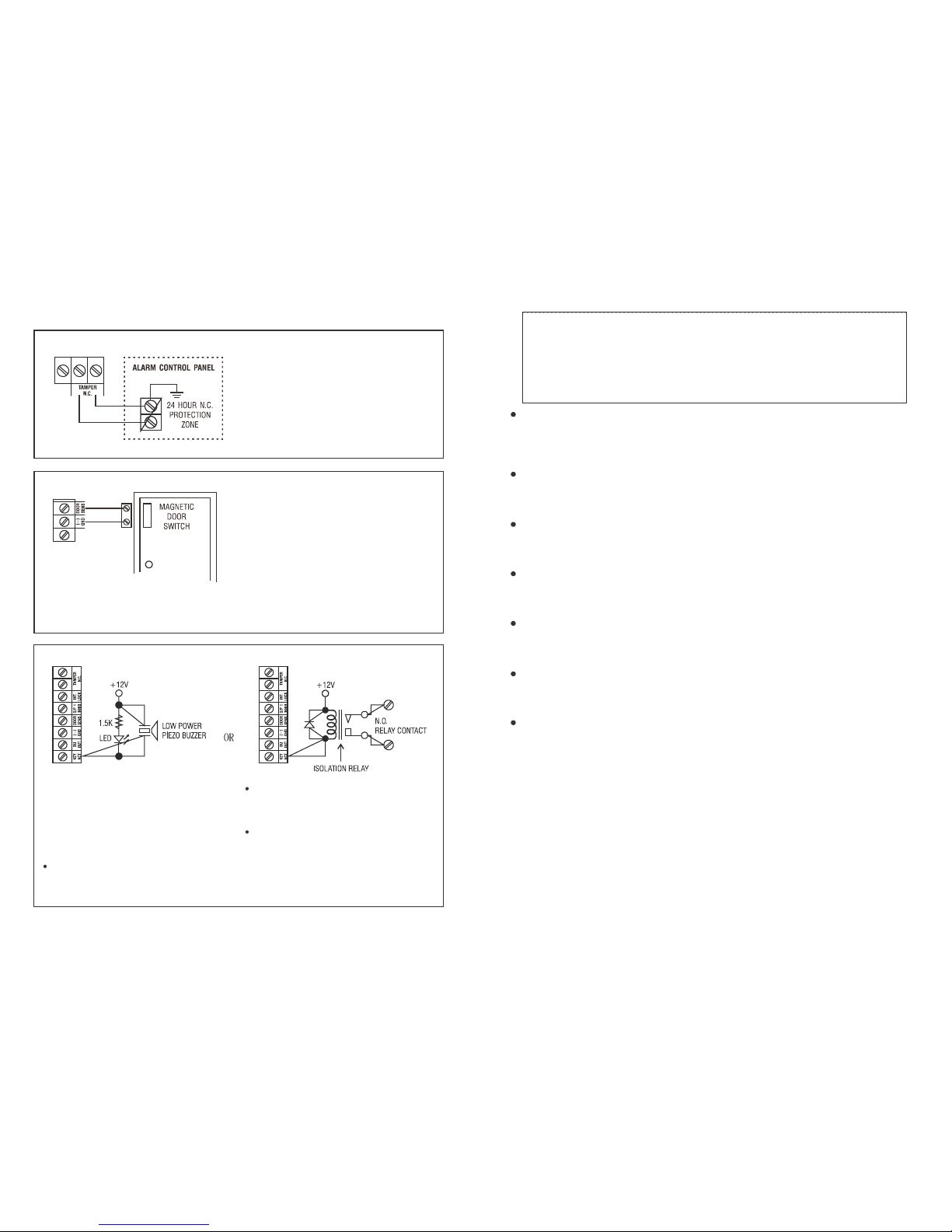
The Duress Output will switch to (-) ground whenduress code is entered. You may use it to turn ON an LED
lamp and/ or a small buzzer to notify a guard; or connect it to a 24 hour Normally Open protection zoneof an
alarm system.
Use the Normally Open (N.O.) output contact to shunt a Normally Closed (N.C.) protection zone of an alarm
system.
Set output contact toStart / Stop Mode (ProgrammingOption51).
Use the(N.O.) or (N.C.) output contact to make arm-disarm control of analarm system.
Consult your alarm control panel manual for theappropriate output contact to be usedin arm-disarm control.
Usually set output 2 to Momentary mode (Programming Option 501) for multi station systems and Star t /
Stop mode (Programming Option 51) for single stationsystems.
Only one connection optionis recommended. Makesurethat the sinkcurrent does not exceed the maximum
ratingof 100mA.
(D) DURESSOUTPUT
(E) OUTPUT2
( i ) Shuntingan N.C. Zone
( ii ) Alarm SystemArm-DisarmControl
DC50FS & ITS BACK BOX
DC50SS
DC60SS
Page 3
The Key ActiveOutput will switch to (-) ground
for 10 seconds whenever a key is touched. You
may use it to turn ON an LED lamp and /or a
small buzzer to notify a guard; or to energize
a relay to switch ON lights or trigger an CCTV
Camera tostar t recording.
Make sure that the relay for switching ON
lights has high enough isolationbetween high
voltage and low voltage to prevent damage of
the keypad.
Only one connection option is recommended.
Make sure the sink current does not exceed the
maximum rating of 100mA.
External power supply and isolation relay are
strictly necessary in driving high power device,
such as lights.
APPLICATION HINTS FOR THE AUXILIARY TERM INALS
The tamper switchis Normally Closed while the keypad
is secured on gang box. It is open when the keypad
is removed from the gang box. To prevent sabotage,
connect these terminals in series with a 24 hour N.C.
protectionzone of analarm system if required.
With the help of a Normally Closed door
position sensor ( usually a magnetic door
switch) on the door to set up the following
functions:
Door Auto Relock - - The system will immediately
relock the door after a valid access has beengained to
prevent "tailgate" entries.
Door Forced-open Alarm -- The keypad will generate
alarm instantly if the door is forced toopen. Enable the
function with Programming Option801.
Door Propped-up Alarm -- The keypad will generate
alarm if the door is left open longer than the pre-set
del ay time. Enable the function with Programmi ng
Option 9 with time of 1 to 999 seconds possible.
Inter-lock Control -- When t he door is open, the
interlockoutput of the keypad will give a(-) command
to stop the other keypad inan inter-locksystem.
a)
b)
c)
d)
(A) TAMPERN.C.
(B) DOOR SENS
(C) KEY ACTIVE
18
12-24V AC/DC(POWERINPUT)
Connect to 12-24V AC or DCpower supply. The (-) supply and (-) GNDarethe common grounding points of the
keypad system. No selectionjumperis required for thefull input voltage range.
Connect DC power with the (+ ) and (-) polarity indicated; and there is no polarity discrimination for AC power
input.
OUTPUT1
5 Amp relay dry contacts, recommended for door strikecontrols. Normally Open (N.O.) andNormally Closed (N.C.)
outputs are available. Use N.O. output for Fail-secure locking device and N.C. output for Fail-safelocking device. The
relay can be programmed in Start/Stop(toggle) mode or timermode from1 to 999 seconds.
OUTPUT2
This is an auxiliaryoutput controlled by theUser Code2, whichis ideal for controlling security systems &automatic
operators. It is programmable forStart / Stop (toggle) operationor timingoperation from 1 to 999 seconds.
It isa relayoutput with 1Amp rating Normally Open (N.O.) and NormallyClose (N.C.) dry contacts.
EGIN(EGRESS INPUT)
A Normally Open (N.O.) input terminal refers to (-) ground, with thehelp of a normally open button to activate the
Output 1 for the same time period as the user code. Egress button is usually put inside the house near the door.
More than oneegress buttons can be connected inparallel tothe terminal. Leave this terminal open if it is not used.
KEY ACT.(KEYPAD ACTIVE OUTPUT)
An NPNtransistor open collector output. It switches to (-) ground for 10 seconds on eachkey touching. This can
beused to turn on lights, CCTVcamera, or buzzer tonotify a guard.
The rating of thisoutput is: Ic max: 100mA sink, Vc max: 24VDC
DU OUT (DURESSOUTPUT)
An NPN transistor open collector output. It switches to (-) ground after theDuress Codeis entered. Useit to trigger
analarm zone, or turn ona buzzer tonotify aguard.
Ic max: 100mAsink. Vc max: 24VDC
DOOR SENS(DOORPOSITION SENSOR INPUT)
A Normally Closed (N.C.) input terminal referring to (-) ground. With thehelp of a normally closed magnetic door
switch, the system will monitor thepositionof the door and will givethefollowingfunctions:
NOTE: Always connect this terminal to (-) ground if not used.
1)
Door Auto Re-lock
2)
3)
4)
3
NOTE:
(1)
Cut a rectangular holeon wall carefully for theback box in its right sizeanddepth to ensure thatthe back
box and the faceplatecan be tightlyshielded together with its rubberpadwhile they are fixed onwall.
(2)
The four holeson the back sideof the box areprepared for fixingtheback box on solid wall withscrews.
(3)
The four holeson the front edge oftheboxareprepared for fixing the back box on hollowwooden wall.
(4)
Thetamper switch of the DK-2880A ismagnetically activated. A magnet is equipped on the back of the
back box.The tamper switch is closed circuit (N.C.) while the keypad isfixed on its backbox.
The system will immediatelyrelock the doorafter valid access has been gained beforetheend of the programmed
time for output 1, that prevents unwanted "tailgate" entries.
Door ForcedOpenAlarm
The keypad will generatedoor forced-open alarm instantly if the door isforced to open without a valid user entry
or egress input. Thealarm will last for 60 seconds and can be stopped withuser code 1or oneof the usercodes
in Group 1at anytime. This functionis selectablevia the programmingoptionsat Location80.
Door Propped-up Alarm
When thedoor is left open longer than the allowabletime. The keypadwill generate door propped-up alarmafter
the expiryof the pre-set door-open-time until the door is closed again. The door-open-time is programmable from
1 to 999 secondsat Location9.
Inter-lockControl
The inter-lockcontrol output goes to(-) while the door is openin orderto givesignal to disable the other keypad
in the inter-locksystem.
Page 4

THE LED INDICATORS
RED-- It lightsup whenoutput 2 isactivated.
AMBER-- This is astatus indicator. Its signal is insynchronization with the pacifiertonesfromthebuilt-inbuzzer.
GREEN -- It lightsup when the output 1 is activated.
THE PACIFIER TONES & THE LED INDICATING SIGNALS
The built-in buzzer and theamberLED indicator give thefollowing tones and signals for operation status:
STATUS TONES
*
LED SIGNALS
1. In programmingmode
- - -
ON
2. Successful key entry 1 Beep 1 Flash
3. Successful codeentry 2 Beeps 2 Flashes
4. Unsuccessful code entry 5 Beeps 5 Flashes
5. DAP jumper not replaced ContinuousBeeps Continuous Flashes
6. In standby mode
- - -
1 Flash in 2 secondsinterval
7. Output relayactivated
1 second Long Beep
* *
- - -
NOTE:
*
All Pacifier Tonescanbe enabledor disabled through programmingoptions at Location83.
* *
The Output Activation Beep can be enabled or disabled through programming options at Location81.
THE DAP JUMPER (DIRECT ACCESS TO PROGRAMMING)
If the Personal Master Code is forgotten, use the DAP jumper tooverridetheforgotten code permittingthekeypad direct
entry into programming mode. Youarerequired toapply the followingprocedures precisely.
1. Disconnect power supply.
2. DisplacetheDAPjumper from OFFto ON position.
3. Reconnect power supply (buzzer is activated).
4. Put the DAP jumper back toOFFposition (this done, thebuzzer isde-activated).
5. The keypad isin programming modeand ready to receivenew programming data.
6. As the old mastercode was forgotten, suggest you toput a4 digit new master codeinto Location0 first.
7. Enter the new programming datastarting from Section(B) in the summary chartshown below.
THE FACTORY-SET MASTER CODE
-- IMPORTANT NOTE
For theowner'sconvenience inprogramming at thefirst time, the factory has put a Master Code 0000 into the keypad.
To compromisesecurity, in all cases, the owner should program a Personal Master Code to invalidate the factory-set
Master Codebeforeuse.
THE BACK-LIT JUMPER
1. FULL-------
Thekeypad gives dim backlit in standby. It turns to full backlit whena key button is pressed, thenback to
2. QUASI -----
3. OFF--------
dimbacklit 10 seconds after the last key buttonis pressed.
The Keypad gives no backlit instandby. It turns to full backlit when akey button is pressed, then back to
OFF 10 seconds afterthelast key buttonis pressed.
The keypad gives nobacklit at all.
An inter-lock system needs two door controllers. This application exampleuses two of DC60SS, DC50SS or DC50FS
with simple cross wire connectionon their "Output 1 Inhibit" and "Inter-lock Control Output" terminals. It is necessary to
link upthe"(-) GND" terminals of thetwo keypads as common ground toachieve the inter-locklogical functions.
Use keypad toopen the door from outside
Press egress buttonto openthedoor from inside
Connect the door magnetic sensors on the doors to monitor their positions
Whiledoor 1 is open, then,door 2is forcedto keep close, or vice versa
Use N.O. Relay output for fail-securelock; and N.C. output for fail-safe lock
Please also see the "NOTE" stated intheApplicationExample (1)
4
17
O/P 1 INHIB. (OUTPUT 1INHIBIT)
A Normally Open (N.O.) input terminal refers to (-) ground. Both user code 1 and Egress button can not activate
output 1 whilethis terminal is tied to (-) ground. It is prepared for cross wire connection inInter-lock application.
INT. LOCK (INTER-LOCK CONTROL OUTPUT)
An NPNtransistor open collector output. It is OFF at normal condition and switches to (-) ground immediately for
the first 5 seconds after keying ina valid user code tooperate output 1, then, it will keep tying to (-) ground during
the time that the door positionsensor is opendueto door opening. Use thisoutput tocontrol theother keypad inan
inter-lock system to prevent bothdooropeningat the same time.
An inter-locksystem isa two-door system that always allows only one doorto openduring the operation time. While
one of the doors in the system is opened, the other door keeps close until the firstly opened door is re-closed in
order to prevent theunauthorized peopledashingintoaprotected area.
N.C. TAMPER
Normally Closed contact while the keypad is securedon the box. It isopen while keypad is separated from the
box. Connect this N.C. terminal to the24 hour zone of analarm system if necessary.
3) BASIC WIRINGS OF AN INTER-LOCK SYSTEM USI NG TWO KEYPADS
Page 5

PROGRAMMING OPTIONS -- SUMMARY CHART
5
A) Use TheFactory-setMaster Code to Entryin Programming-- When starts forthe firsttime
Entry of Code
0 0 0 0
User ModeOptions
8 9 0 0
8 9 0 1
Locations
0
1
2
Locations
7 0
7 1
7 2
7 6
Locations
4 0
4 1
4 2
5 0
5 1
5 2
Locations
0
1
2
i) Recording of the master code anduser codesfor SingleUser (Digitsmay be repeated)
ii) Recording of themastercode anduser codesfor Multi-User (Digitsmay be repeated)
Validation
*
Validation
#
#
Validation
#
#
#
Validation
#
#
#
#
Validation
#
#
#
#
#
#
Validation
#
#
#
Entry of Codes
4 digits,fixed
4 digits,fixed
4 digits,fixed
No. of FalseEntry
5 to10
00
Codeof Duration
1 to999
1 to 999
Entry of Codes
4 to 8 digits
4 to 8 digits
4 to 8 digits
User Number
00 to 99
0 to9
Comments
Set system into ProgrammingMode with the Factory-set Master Code
Comments
Set system to SingleUser Mode, clear all thedatapreviouslystoredand refreshsystem
Set system to Multi UserMode, clearall thedatapreviouslystoredand refresh system
Comments
Personal Master Code& Super User Code
User Code 1 for output1 with Duress Codefunction
User Code2 for output 2
Comments
After 10 successivefalse codes, the keypadlocks during 30 seconds
After 10successive falsecodes, theDuressoutput switches toground
Selectable of after 5 to 10 successive false codes, the keypad locks during 15
minutes. The keypad canbereset torelease locking with theMaster Code at any
time duringthe locking period
Disappearanceofalltheabove securities
Comments
Output1 inMomentary Modefrom 1 to 999 seconds
Output1 inStart /Stop Mode(toggle)
Output1 inStart /Stop Mode(toggle)withaccelerated code
Output2 inMomentary Modefrom 1 to 999 seconds
Output2 inStart /Stop Mode(toggle)
Output2 inStart /Stop Mode(toggle)withaccelerated code
Comments
Personal Master Code& Super User Code
100 User Codes inGroup 1 for output 1 with Duress Code
function
10 User Codes inGroup 2 foroutput 2
B)Set SystemtoSingle User or Multi User Mode & Refresh The System -- Installer Programming
C) Recording of Personal Master Code & User Codes -- User Programming
E) Personal Safety -- Installer Programming
D) Configurationof Output Modes -- Installer Programming
2 ) B AS IC W I RI NG S OF A ST AN D ALO NE DO OR L OCK W IT H INH IBI T
AUTHORIZATION CODE
Use output 2 as authorization control. The owner may key in the user code 2 to stop the operation of the electric
lock inthenight timeor after officehour to prevent unauthorizedaccess.
Set output 2in Start / Stop mode (Programming Option 51) for ON-OFF control.
Simply connect the"output 1 inhibit" (O/P1 INHIB) terminal with output 2 as like the wiring diagram shown. User
code1 isinvalid whilethe"O/P 1INHIB" terminal isshunted toground with user code2.
16
Page 6

F) Door Forced-OpenAlarm -- Installer Programming
I) Pacifier Tones (Keypress Acknowledgement Tones) -- Installer Programming
J) Allowable Time toStart Door Propped-up Alarm -- Installer Programming
K) Exit Programming Mode
G) OutputActivationAnnouncer -- Installer Programming
H) User Code Entry Mode (Autoor Manual) -- InstallerProgramming
Locations
8 0
8 0
Locations
8 3
8 3
Locations
9
9
Locations
8 1
8 1
Locations
8 2
8 2
Validation
#
#
Validation
#
#
Validation
#
#
Validation
*
Validation
#
#
Validation
#
#
Codeof Functions
1
0
Codeof Functions
1
0
Codeof Functions
0
1 to999
Codeof Functions
1
0
Codeof Functions
1
0
Comments
DoorForced-OpenAlarmis Enabled
DoorForced-OpenAlarmis Disabled
Comments
Pacifier tones availableonkeypress
All pacifier tonesareoff. Good for placerequiressilent environment
Comments
No propped-up alarm
Allowabletime from 1 to 999 seconds for door left open before the door
propped-upalarmstarts
Comments
Keypadexitsprogrammingmodeandreturns tonormal operation
Comments
1 second notifying beep is given tonotify the person outside to open thedoor
when output relay is activated with anuser codeor egress button. Good for the
lockingdevice that gives no sound when it activates, suchasa magnetic lock.
Notifyingbeepdisabledandreplaced by2 short successful code entry beeps for
validuser codes
Comments
Auto Entry Mode isselected.#key that follows theuser codeisNOTrequiredin
code entry. TheUser Codes MUST be set in thesame digitlengthas theMaster
CodeinAuto Entry Modeand the codelengthcanbe4-8 digits.
Manual Entry Modeis selected.#key that follows theuser codeis required in
code entry. Theuser codes can be4-8 digits andthey are not required to be in
the samelengthasthe Master Code.
InSingle User Mode, nomatter the selection is Autoor Manual mode, the MasterCode andtheUser Code MUST be set in
the length of 4 digits.
NOTE:
6
15
APPLICATION EXAM PLES
1) BASIC WIRIN GS OF A STAND ALONE DOOR LOCK
NOTE:
Connect the 1N4004 as close as possible to the lock in parallel with the lock power terminals to absorb theback
EMFto prevent it from damaging the keypad. The1N4004 isnot requiredif the electric lock isACoperated.
To avoid Electro-Static-Discharge from interfering withthe operation of the keypad, always ground the (-) terminal
of the keypadto earth.
Always connect DOOR SENSOR terminal to (-) ground if not used.
Page 7

SINGLE USER MODE OR M ULTI-USER MODE SELECTION
The keypad consists two sets of software for owner's selection in user code programming. They are "Single User
Mode" and "Multi-User Mode".
The keypad has been set with a Master Code of "0000"andin Single User Mode at the factory. If your requiredmode is
Multi-User, youhave torefreshthesystem with the appropriatecomment code, 8901, to set itintoMulti- UserMode.
Single User Mode (Command Code: 8900)
Single User Mode isprepared for the simpleusers, whichallows only one user code tooperate each output. The user
codes are fixed to 4 digits and 10,000 code combinations are possible. User codes can be programmed directly into
the User Code Location 1 and Location 2. PleaseseeProgrammingSummar yChart Section (C), itemi) for details. This
mode is always set with Auto Code Entry in default. Theuser does not require to press the#key in user codeentry.
The user only needsto enter the4 digit user code. Therelay will activate for theprogrammed time.
NOTE: Thesystem can be set for Manual Entry with programmingoption0 atLocation82 ifrequired.
Multi-User Mode (Command Code: 8901)
Multi-User Modeallows up to100 individual usercodes tooperate the output 1 and 10 individual usercodes tooperate
the output 2. The user codes can be 4 to 8 digits with over 100 millioncode combinations. The user codes can beset
for Auto Entry or Manual Entry with programming options at Location 82. Manual Entry Mode is in default. The user
codefollowed by#key isrequired.
Once the keypad is programmed in Auto Entry, theMaster Code and the User Codes MUST be set in the samedigit
length, and the need for theuser codenot tobe followed by#key isrequired.
The Default Values
Default Values
401
501
70
800
811
820
821
831
90
Comments
Output 1in 1 second Momentary Mode
Output 2in 1 second Momentary Mode
After 10 successive falsecode, the keypad locks during 30 seconds
Door forced-openalarm disabled
Output relay activation beep ON
UsercodeManual EntryMode ** (For Multi-User Mode)
UsercodeAuto Entry Mode ** (ForSingle-User Mode)
Pacifier Tones ON
No propped-upalarm
NOTE: ** The default values in Multi-User Mode and Single User Mode areexactly the same except the User Code
For example:
EntryMode.
An User Code 56789 was stored in thesystem, then 36789 and 76789 are not allowed for other User
Codes.
Code Entry Limitation inMulti-User Mode dueto Duress Code
The system comes withDURESS functionfor the user code1in Single User Mode and all the user codes of Group 1in
Multi-User Mode; The DURESSCODE is set upby the systemautomatically with the first digit of the User Code "+ 2".
To preventtheother User Codes fall into the Duress Code, orthe Duress Codesfall into otherUser Codes, the first digit
of a "Stored"User code"+ 2" or "-2"is not allowed for the laterUser Code entryin programming. The system will refuse
those code entries.
14
7
Page 8

8
13
SET THE SYSTEM TO SINGLE USER MODE
The system can be set to Single User Mode with the command code "8900" and will stay in that modeuntil the system
is refreshed for other mode. Makesure that the Master Code wasalready in 4digits before settingthe system to Single
UserMode.
MASTER CODE
* 8 9 0 0 #
----- Single User Mode on Duty (please wait 2-3 seconds until the confirmation
SET THE SYSTEM TO MULTI-USER MODE
The system can be set to Multi Users Mode with the command code"8901" and will stay inthat mode until the system
is refreshedfor other mode.
MASTER CODE
* 8 9 0 1 #
----- Multi-User Mode on Duty (please wait 2-3 seconds until the confirmation
REFRESH THE SYSTEM
-- WHEN IN CHANGE OF OPERATION MODE
The system can be changed from Single User Mode to Multi-User Mode; or vice versa with the above operation
command codes.
When this isdone, the keypad will reset itself as afreshunit with thedefault values; and all the previously programmed
data will becleared except theMaster Code.
IMPORTANTNOTES:
1)
Make sure all the User Codes and Master Code are in the length of 4 Digits if the system is in Single User Mode
operation. Otherwise, code entrywill not be accepted.
2)
It is necessary to change the Master Code in thelength of 4 digits first (no matter it was in4 digits or morethan 4
digits in Multi- User Mode) beforerefreshing it from Multi-User Mode to Single User Mode.
3)
The system takes approximate2 to 3seconds to refresh itself for thenew operation modeafter thecommand code
is entered. DO NOT enter any codeduringthesystem isbeingrefreshed until the 2confirmation beeps are heard.
D) DELETEUSER (MULTI-USERMODE)
If you need to delete auser who hasleft the companyor who nolonger hasauthority toenter theprotected area:
1)
Set system inprogramming modewith the Personal Master Code and the*key
3 2 8 9 *
------------ Thekeypad is now intheprogrammingmode
2)
Enter the User Number (00-99 for output 1; 0-9for output 2) and the key#to delete auser code
If you want todeleteUser Number 05 in Group1, press
1 0 5 #
If you want to delete User Number 3in Group2, press
2 3 #
3)
Youmay delete other usercode(s) in this fashion
4)
Exit the programmingmode by pressing the*key after the work isdone
beeps areheard after thekey#is pressed)
beeps are heard after the key#is pressed)
Page 9

12
c)
d)
For example:
NOTE:
e)
Example:
f)
The Personal Master Code is a Super User Code to command the outputs. This feature allows the owner
to use only one code to operate several keypads if they are having the same Master Code but different
user codes. Enter the Personal Master Code and validate via and the corresponding output number.
The Duress Codes do not need to be programmed. The keypad determines them automatically by
increasing the first digit of the User Codes in Group 1 of Two units. All the User Codes have Duress
Code Function.
0321
8321
31223 11223
53221 33221
To command the Duress Function, enter the Duress Code(s).
The Duress Code(s) has double actions. It activates the Duress Output and at the same time activates
the Output 1 as like the normal User Codes in Group 1. The Duress Code(s) can always activate or
deactivate (in Star t / Stop mode) Output 1, but cannot deactivate (reset) the Duress Output. ONLY the
User Codes in Group 1 can deactivate (reset) the Duress Output.
The Accelerated Code is the First Two Digits of the User code(s). If the Output has been programmed in
Star t / Stop mode with Accelerated Code (Programming Option 42 for user codes in Group 1 and
Programming Option 52 for user codes in Group 2), it is possible to activate the Output with only the
First Two Digits of the User Code(s). Deactivating of the Output always requires the composition of the
Complete User Code(s) in their code Group.
Output 1 has been re-programmed to Start / Stop Mode with Accelerated Code (Programming Option 42)
with the Complete Code of 1st User Code in Group 1:
8321
The Accelerated Code is:
83
2nd User Code in Group 1:
11223
The Accelerated Code is:
11
Try to put some random false codes to the keypad to test its Safety. The keypad generates 5 beeps for
each unsuccessful code entry. The keypad locks itself during 15 minutes after 10 successive false codes
are entered. Normal operation will resume after 15 minutes expired, or, it can be reset with the Master
Code during the locking period.
---
Output 1 activates for 1 second
---
Output 2 starts or stops
-----
Duress output activates (output switches to ground) & Output 1 activates for 1 second
--
Duress output activates (output switches to ground) & Output 1 activates for 1 second
--
Duress output activates (output switches to ground) & Output 1 activates for 1 second
-------------
Output 1 starts
------
Output 1 stops
-------------
Output 1 starts
---
Output 1 stops
------ Locking
is reset and keypad resumes normal operation
The User Codes in Group 1 The Corresponding Duress Codes
9
PROGRAMMING AND USE OF THE KEYPAD
--
OPERATION EXAMPLES
a)
b)
NOTE:
c)
d)
All programming is accomplished entirely from the front of the keypad. The keypad may be programmed in
your shop or at the installation site. Programmed information is stored in non-volatile memory so it will not
be lost if power is removed.
When programming is required. It is necessary to set the keypad into programming mode first with the
master code and validating it with key.
If the master code is forgotten, please use DAP jumper to set the keypad into programming mode.
See DAP JUMPER description in previous section for the details.
After the keypad is in programming mode, you may go to any Location for your programming options one by
one, please see Programming Options Summary Char t for the feature details.
You may make continuous programming until all desired options are programmed. Repeated programming at
the same Location is allowed if the previous entry was mistaken.
MASTER CODE
LOCATION 1 OPTION
LOCATION n OPTION n
I
I
e)
1) Re uirement
Exit programming mode with the key after all your required options are programmed. The new information
that you have just programmed is saved.
a) Single User Mode Operation
b) Change the factory-set Master Code 0000 to a Personal Master Code 3289
c) Set User Code 1 of 8321
d) Set User Code 2 of 6854
e) Set Output 1 to Momentary Mode, 1 second
f ) Set Output 2 to Start / Stop Mode
g) Set the keypad to lock itself during 15 minutes after 10 successive false codes
-- 6854 has been stored as User Code 2, for output 2
-------------- Output 2 has been set to Start / Stop Mode
data
2) Programming -- Set the above requirement into the keypad:
------- System has been set in programming mode with the factory-set Master Code
------- System has been set for Single User Mode* * (please see NOTE(a) below)
-- 3289 has been stored as the new Personal Master Code & Super User Code
-- 8321 has been stored as User Code 1, with Duress Code function, for output 1
--------- Output 1 has been set to Momentary Mode, 1 second
----- The keypad has been set to lock during 15 minutes after 10 successive false codes
----------------------- Keypad exits programming mode. All the above are stored and ready for use
A) PROCEDURES OF PROGRAMMING
B) SINGLE USER MODE OPERATION -- An Example
q
Page 10

NOTE:
a)
c)
For example:
NOTE:
Example:
a) * *Enter the Single User Mode Command Code "8900" may not be necessary if the keypad was
already in Single User Mode.
b) In case of wrong entry during programming, cancel it with key, or, wait 10 seconds, then re-try.
To command an output, only enter its user code. Press is NOT required.
The Duress Code does not need to be programmed. The keypad determines it automatically by
increasing the first digit of the User Code 1 of Two units.
The User Code 1 is "1234", then the Duress Code is "3234"; or the User Code 1 is
"8321", then the Duress Code is "0321".
To command the Duress Function, enter the Duress Code.
The Duress Code has double actions. It activates the Duress Output and at the same time activates the
Output 1 as like the User Code 1. The Duress Code can always activate or deactivate (in Start / Stop
mode) Output 1, but cannot deactivate (reset) the Duress Output. ONLY the User Code 1 can deactivate
(reset) the Duress Output.
Output 1 has been re-programmed to Start / Stop Mode with Accelerated Code (Location: 42)
with the Complete Code of:
8321
The Accelerated Code will be:
83
-----------
Output 1 activates for 1 second
----------- Duress output activates (output switches to (-) ground) & Output 1 activates for 1
second
Output 1 starts
Output 1 stops
------ Locking
is reset and keypad resumes normal operation.
3) Operate The Keypad
b)
d)
e)
-- Taking the data programmed above and other features in default value as reference
The Personal Master Code is a Super User Code to command the outputs. This feature allows the owner
to use only one code to operate several keypads if they are having the same Master Code but different
user codes. Enter the Personal Master Code and validate via and the corresponding output number.
The Accelerated Code is the First Two Digits of the User Code. If the Output 1 has been programmed in
Star t / Stop mode with Accelerated Code at Location 42, it is possible to activate the Output 1 with only
the First Two Digits of the User Code. Deactivating of the Output 1 always requires the composition of
the Complete User Code 1.
Try to put some random false codes to the keypad to test its Safety. The keypad considers 4 digits as
one code and it generates 5 beeps for each unsuccessful code entry. The keypad locks itself during 15
minutes after 10 successive false codes. Normal operation will be resumed after 15 minutes expired, or,
it can be reset with the Master Code during the locking period.
-----------
Output 2 starts or stops
---
Output 1 activates for 1 second
---
Output 2 starts or stops
-------------
-----------
10 11
C) MULTI-USER MODE OPERATION
-- An Example
1) Requirement
2) Programming
NOTE:
3) Operate The Keypad
a)
b)
a) Multi-User Mode Operation
b) Change the factory-set Master Code 0000 to a Personal Master Code 3289
c) Set 1st User Code in Group 1 of 8321
d) Set 2nd User Code in Group 1 of 11223
e) Set 3rd User Code in Group 1 of 33221
f ) Set 1st User Code in Group 2 of 6854
g) Set 2nd User Code in Group 2 of 54321
h) Set Output 1 to Momentary Mode, 1 second
i ) Set Output 2 to Start / Stop Mode
j ) Set the keypad to lock itself during 15 minutes after 10 successive false codes
-- Set the above requirement into the keypad
a) **Enter the Multi User Mode Command Code "8901" may not be necessary if the keypad was
already in Multi User Mode.
b) In case of wrong entry during programming, cancel it with key, or, wait 10 seconds, then re-
try.
-- Taking the data programmed above and other features in default values as reference
To command output 1, enter any one of the User Codes in Group 1 and validate via the key
To command output 2, enter any one of the user codes in Group 2 and validate via the key.
-------------------- System has been set in programming mode with the factory-set Master Code
-------------------- System has been set for Multi User Mode* * (please see NOTE (a) below)
--------------- 3289 has been stored as the new Personal Master Code&Super User Code
------- 8321 has been stored as the1st User Code in Group 1 with Duress Code function
---- 11223 has been storedas the 2nd User Codein Group 1 with Duress Code function
---- 33221 has beenstored as the3rdUser Codein Group 1with Duress Code function
---------- 6854 has been stored as the 1st User Code in Group 2
------ 54321 has been stored as the 2nd User Code in Group 2
----------------------- Output 1 has been set to Momentary Mode, 1 second
---------------------------- Output 2 has been set to Start / Stop Mode
------------------ The keypad has been set to lock during 15 minutes after 10 successive false
codes
------------------------------------ Keypad exits programming mode. All the above data are stored and ready for
use
------
Output 1 activates for 1 second
---
Output 1 activates for 1 second
---
Output 1 activates for 1 second
------
Output 2 starts or stops
---
Output 2 starts or stops
 Loading...