

Page 1
EN
TECHNICAL
MANUAL
Ciao Series Entrance panel
Art. CA2100P-CA2200P
Passion.Technology.Design.
Page 2

Warning
Intended use
This Comelit product was designed for use in the creation of audio and video communication systems in residential,
commercial or industrial settings and in public buildings or buildings used by the public.
Installation
All activities connected to the installation of Comelit products must be carried out by qualified technical personnel, with
careful observation of the indications provided in the Manuals / Instruction sheets supplied with those products.
Wires
Cut o the power supply before carrying out any maintenance procedures.
Use wires with a cross-section suited to the distances involved, observing the instructions provided in the system
manual.
We advise against running the system wires through the same duct as the power cables (230V or higher).
Safe usage
To ensure Comelit products are used safely:
• carefully observe the indications provided in the Manuals / Instruction sheets
• make sure the system created using Comelit products has not been tampered with / damaged.
Maintenance
Comelit products do not require maintenance aside from routine cleaning, which should be carried out in accordance
with the indications provided in the Manuals / Instruction sheets.
Any repair work must be carried out
• for the products themselves, exclusively by Comelit Group S.p.A.,
• for systems, by qualified technical personnel.
Disclaimer
Comelit Group S.p.A. does not assume any responsibility for
• any usage other than the intended use
• non-observance of the indications and warnings contained in this Manual / Instruction sheet.
Comelit Group S.p.A. nonetheless reserves the right to change the information provided in this Manual / Instruction
sheet at any time and without prior notice.
Table of contents
Warning ............................................................................................ 2
Description ....................................................................................... 3
Art. CA2100P .............................................................................................3
Art. CA2200P .............................................................................................4
Technical features ........................................................................... 5
Art. CA2100P .............................................................................................5
Art. CA2200P .............................................................................................5
Installing entrance panel Art. CA2100P ......................................... 6
Changing nameplates ..................................................................... 6
Installing entrance panel Art. CA2100P with button module Art.
CA2200P ........................................................................................... 7
Connections ..................................................................................... 9
Variants .....................................................................................................9
Call button addressing .................................................................. 10
Special programmes ..................................................................... 12
Operating notes ............................................................................. 13
System performance and layouts ................................................ 13
Addressing table ............................................................................ 14
2
Page 3
Description
Ciao Series modular entrance panel with die-cast aluminium front cover and nameplates with white LED backlighting. To be
finished with 1/2/4/8 call buttons, available to purchase separately.
Featuring a Smart button programming mode. Supplied with a surface-mount installation support.
Entrance panel art. CA2100P can be used alongside up to 4 button modules art. CA2200P (both horizontally and vertically) to
reach a maximum of 72 call buttons.
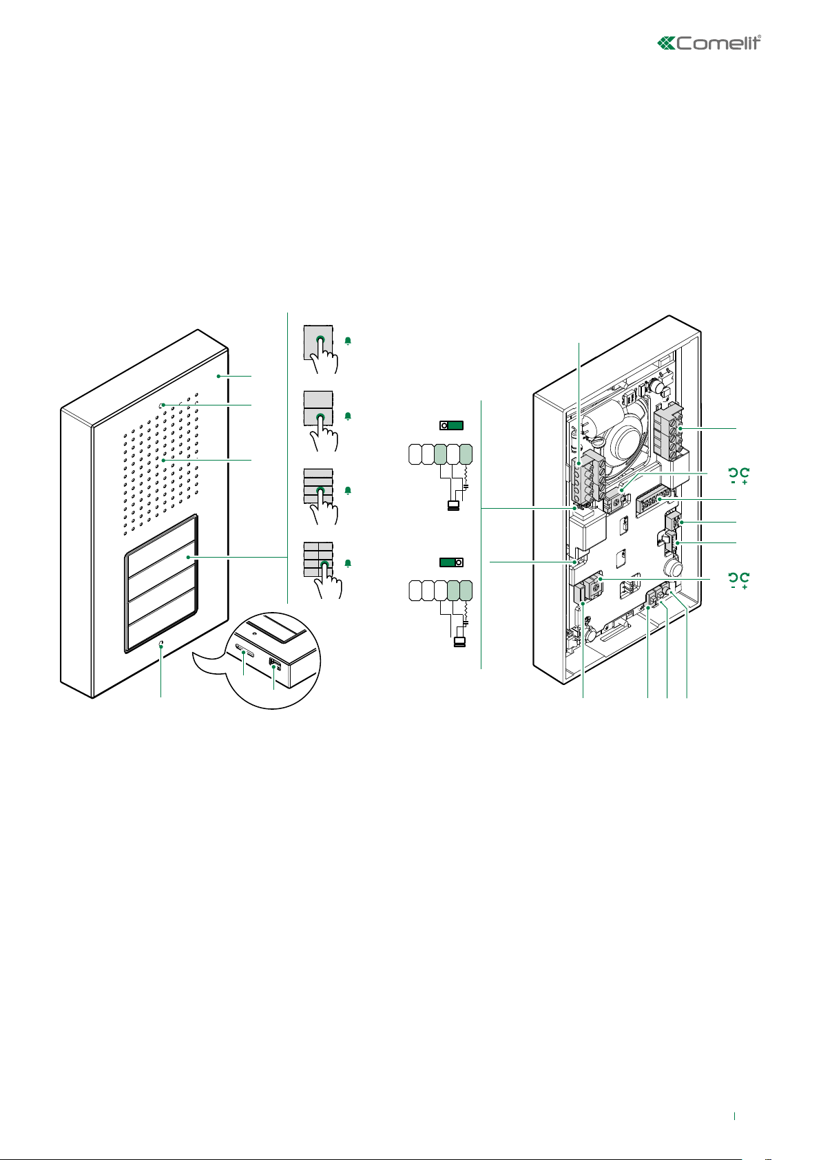
Art. CA2100P
art. CA9213
1
9.
1.
2.
3.
4.
6.
2.
art. CA9210
1
2
art. CA9211
1
2
3
4
art. CA9212
1
2
3
4
5.
5
6
7
8
1. Die-cast aluminium cover
2. Faceplate fixing screw holes
3. Loudspeaker
4. Call buttons 1 / 2 / 4 / 8 users (available to purchase
separately)
5. Microphone
6. Condensation drainage hole
7. CV2 jumper to be removed when switching o the button
lighting
8. JP1 enabling the RC network for door lock filter on relay
contacts
9. Terminal block for J4 connection:
SE- SE+ connection for electric door lock
NC NO C relay contacts
10. Terminal block for J3 connection
L L bus line connection
COM RTE and DO reference negative
DO door open indication
RTE request to exit button
NC
NO
JP1
SE-SE
NC NO C
+
11.
8.
JP1
SE-SE
NC NO C
+
NO
7.
15.
18. 16.17.14.
NC
11. LED button brightness control trimmer
12. S2 dip switch for button addressing and special function
programming
13. S1 dip switch for button type configuration (1 / 2 / 4 / 8
users)
14. J2 and J5 6-pole connectors for button module
connection
15. SPK loudspeaker volume adjustment trimmer
16. SW1 programming confirmation button
17. PRC call address programming input/output switch
18. PRS special programming input/output switch
10.
12.
13.
14.
3
Page 4
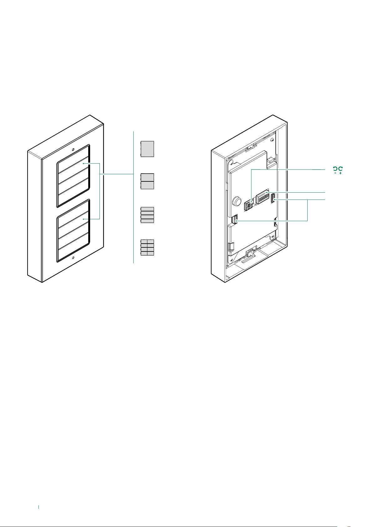
Art. CA2200P
art. CA9213
art. CA9210
1.
art. CA9211
art. CA9212
1. Call buttons 1 / 2 / 4 / 8 users (available to purchase
separately)
2. TM1 button brightness control/switch o trimmer
3. S1 dip switch for button type configuration (1 / 2 / 4 / 8
users) and button module addressing
4. J1 and J2 6-pole connectors for Art. CA2100P / CA2200P
connection
2.
3.
4.
4
Page 5

Technical features
Art. CA2100P
MAIN FEATURES
Type of power supply BUS
Power supply voltage 27÷34 Vdc (BUS)
Min. absorption (W) 1.7W
Max. absorption (W) 7.6W
Terminals L L COM DO RTE C NO NC SE+ SE-
Removable terminals Yes
Microphone electret
Loudspeaker 8ohm 0.2W
Loudspeaker volume control Yes
Brightness control Yes
IP rating IP 54
IK rating IK 08
Operating temperature -25 °C ÷ +55 °C
Operating relative humidity 25 ÷ 75%
Width 100 mm
Height 172 mm
Depth 28 mm
COMPATIBILITY
SB2 Audio System Yes
Art. CA2200P
MAIN FEATURES
Type of power supply BUS
Power supply voltage 27÷34 Vdc (BUS)
Min. absorption (W) 0.62W
Max. absorption (W) 0.62W
Brightness control Yes
IP rating IP 54
IK rating IK 08
Operating temperature -25 °C ÷ +55 °C
Operating relative humidity 25 ÷ 75%
Width 100 mm
Height 172 mm
Depth 28 mm
5
Page 6

Installing entrance panel Art. CA2100P
ON
1 2
ON
ON
ON
100 mm
28 mm
2
1
172 mm
1
art. CA9213
art. CA9210
art. CA9211
art. CA9212
1 2
1
1 2
S1
2
2 3
3
4
5 6
Changing nameplates
2 31
6
1
2
Page 7

Installing entrance panel Art. CA2100P with button module
5 6
5 6
Art. CA2200P
100 mm
28 mm
2
1
172 mm
3
1
art. CA9213
art. CA9210
art. CA9211
art. CA9212
ON
ON
ON
ON
4
DIP
5
5 6
5-6
S1
6
4
4
4
2
3A
3B
2
1
2
3
3
1
7
Page 8

The addressing of button modules allows, if a module Art. CA2200P is replaced, just the address of the replaced module
Art. CA2200P to be programmed, without having to reprogram all the buttons.
ON
11
1
1
123456
4
1
21 2
1
2 31 2 3
1 2 3 41 2 3 4
MAX 4
modules
11
1
2
2
2
2
2
3
3
3
3
4
4
MAX 4
modules
1
1
1
121
ON
22
123456
ON
33
123456
ON
44
123456
1
S1
2
5 6
7
CA2100P
8
9
8
CA2200P
10
Page 9

Connections
Variant for using the external unit relay
SE-SE
1210/1209
R
C
D
T
NC
NO C
+
O
LL
O
E
M
J5 J2 J1
MAX. 4 modules (72 users)
with 1210
20 m Max. Local lock-release button.
20 m Max. Active input closed for DOOR OPEN signal
Variants
230 V
12V/24V
AC-DC
10A MAX
SE-SE
CA2100P
+CA921x
R
C
D
T
NC
NO C
+
O
LL
O
E
M
CA2200P
+CA921x
CA2100P
+CA921x
“C.NC.NO relay activation on
actuator command: 2 sec”
Set the dip switches permanently as
shown in the figure
Variant for using a safety lock
12/24V
AC/DC
R
C
NO C
D
T
O
LL
O
E
M
SE-SE
NC
+
CA2100P
+CA921x
JP1 enabling the RC network for door lock filter on relay contacts
NC
NO
JP1
SE-SE
NC NO C
+
On C. NO. contacts On C. NC. contacts Excluded: voltage-free contact
JP1
SE-SE
NC NO C
+
NC
NO
JP1
SE-SE
NC NO C
+
NC
NO
9
Page 10

Call button addressing
LL
1 2
CA2200P
3
Code
1 1
Dip switch
ON
1
Set the address of
the apartment you
want to call using
2
1
Press the button you want to associate with the call
address set using the dip switches
the dip switches (see
Addressing table).
Example: code 1
Press the following buttons to assign incremental addresses
+1
+1
+1 +1 +1 +1
2
4A
+1
+1
3
4
5
2
10
1
5
Page 11

If you need to set a NON-progressive address, set the code using the dip switches and press the button you want to
associate with the address.
Example:
code 25
4B
11
Page 12

Special programmes
LL
example
code 208
1
Set the dip switches for the function you wish to program, see the table.
2
1
4 5
Repeat steps 3 and 4 to program other special functions
CODE
195 1,2,7,8
196 3,7,8
197 1,3,7,8
198 2,3,7,8
199 1,2,3,7,8
206 2,3,4,7,8
207 1,2,3,4,7,8
211 1,2,5,7,8
215 1,2,3,5,7,8
216 4,5,7,8
217 1,4,5,7,8
218 2,4,5,7,8
219 1,2,4,5,7,8
220 3,4,5,7,8
221 1,3,4,5,7,8
222 2,3,4,5,7,8
DIP SWITCHES ON
FUNCTIONS
Audio messages
Hebrew
Polish
Catalan
Galician
Basque
Danish
Norwegian
Swedish
Italian
French
Spanish
Dutch
Greek
English
German
Portuguese
3
2
202 2,4,7,8
203 1,2,4,7,8
214 2,3,5,7,8
227 1,2,6,7,8
228 3,6,7,8
12
Enables voice message (door opened warning) when the RTE contact is closed
Disables voice message (door opened warning) when the RTE contact is closed (default
setting)
OFF (default)
Actuator command management
N.B. Art. 1256 in generic actuator mode must not be present in the system.
Actuator function on S serial line = enabled
Actuator function on S serial line = disabled (default)
Page 13

229 1,3,6,7,8
230 2,3,6,7,8
231 1,2,3,6,7,8
245 1,3,5,6,7,8
C.NC.NO relay activation on actuator command: 2 sec
C.NC.NO relay activation on actuator command: 4 sec
C.NC.NO relay activation on actuator command: 8 sec
Door lock
Door lock time: 2 sec + disabling tone (default)
246 2,3,5,6,7,8
247 1,2,3,5,6,7,8
248 4,5,6,7,8
251 1,2,4,5,6,7,8
252 3,4,5,6,7,8
253 1,3,4,5,6,7,8
232 4,6,7,8
233 1,4,6,7,8
234 2,4,6,7,8
235 1,2,4,6,7,8
236 3,4,6,7,8
239 1,2,3,4,6,7,8
240 5,6,7,8
243 1,2,5,6,7,8
244 3,5,6,7,8
208 5,7,8
209 1,5,7,8
Door lock time: 4 sec
Door lock time: 8 sec
Door lock confirmation tone: enabled
Relay C.NC.NO in parallel to SE (default)
Lock-release always enabled (default)
Lock-release only enabled for user called
System functions
Awaiting response time: 60 sec (default)
Awaiting response time: 120 sec
Awaiting response time: 30 sec
Talk time: 90 sec. (default)
Talk time: 180 sec
Confirmation tone on user call = enabled (default)
Confirmation tone on user call = disabled
Awaiting reset time: 10 sec (default)
Awaiting reset time: 1 sec
Reset after lock-release in audio: enabled (default)
Disables “awaiting reset time” on lock-release command (awaiting response time or talk
time will be activated).
249 1,4,5,6,7,8
250 2,4,5,6,7,8
0
255 1,2,3,4,5,6,7,8
254 2,3,4,5,6,7,8
Call transmission: single (default)
Call transmission: triple
System mode
Simplebus (default)
Simplebus Top
Restore default
Operating notes
• When a call is transmitted from the external unit, if a busy tone is heard instead of the ringtone, this means communication
with another external unit is in progress.
System performance and layouts
For further information of system performance and to view installation layouts, click on the system type that best meets your
requirements:
• Kit audio for the creation of audio-video systems for individual residences.
• SB2 audio system for the creation of audio systems for residential complexes.
13
Page 14

Addressing table
Dip switch
Code
ON
1 1 31 1,2,3,4,5 61 1,3,4,5,6 91 1,2,4,5,7 121 1,4,5,6,7 151 1,2,3,5,8 181 1,3,5,6,8 211
1,2,5,7,8
2 2 32 6 62 2,3,4,5,6 92 3,4,5,7 122 2,4,5,6,7 152 4,5,8 182 2,3,5,6,8 212
3 1,2 33 1,6 63 1,2,3,4,5,6 93 1,3,4,5,7 123 1,2,4,5,6,7 153 1,4,5,8 183 1,2,3,5,6,8 213
4 3 34 2,6 64 7 94 2,3,4,5,7 124 3,4,5,6,7 154 2,4,5,8 184 4,5,6,8 214
5 1,3 35 1,2,6 65 1,7 95 1,2,3,4,5,7 125 1,3,4,5,6,7 155 1,2,4,5,8 185 1,4,5,6,8 215
6 2,3 36 3,6 66 2,7 96 6,7 126 2,3,4,5,6,7 156 3,4,5,8 186 2,4,5,6,8 216
7 1,2,3 37 1,3,6 67 1,2,7 97 1,6,7 127 1,2,3,4,5,6,7 157 1,3,4,5,8 187 1,2,4,5,6,8 217
8 4 38 2,3,6 68 3,7 98 2,6,7 128 8 158 2,3,4,5,8 188 3,4,5,6,8 218
9 1,4 39 1,2,3,6 69 1,3,7 99 1,2,6,7 129 1,8 159 1,2,3,4,5,8 189 1,3,4,5,6,8 219
10 2,4 40 4,6 70 2,3,7 100 3,6,7 130 2,8 160 6,8 190 2,3,4,5,6,8 220
11 1,2,4 41 1,4,6 71 1,2,3,7 101 1,3,6,7 131 1,2,8 161 1,6,8 191 1,2,3,4,5,6,8 221
12 3,4 42 2,4,6 72 4,7 102 2,3,6,7 132 3,8 162 2,6,8 192 7,8 222
13 1,3,4 43 1,2,4,6 73 1,4,7 103 1,2,3,6,7 133 1,3,8 163 1,2,6,8 193 1,7,8 223
14 2,3,4 44 3,4,6 74 2,4,7 104 4,6,7 134 2,3,8 164 3,6,8 194 2,7,8 224
15 1,2,3,4 45 1,3,4,6 75 1,2,4,7 105 1,4,6,7 135 1,2,3,8 165 1,3,6,8 195 1,2,7,8 225
16 5 46 2,3,4,6 76 3,4,7 106 2,4,6,7 136 4,8 166 2,3,6,8 196 3,7,8 226
3,5,7,8
1,3,5,7,8
2,3,5,7,8
1,2,3,5,7,8
4,5,7,8
1,4,5,7,8
2,4,5,7,8
1,2,4,5,7,8
3,4,5,7,8
1,3,4,5,7,8
2,3,4,5,7,8
1,2,3,4,5,7,8
6,7,8
1,6,7,8
2,6,7,8
17 1,5 47 1,2,3,4,6 77 1,3,4,7 107 1,2,4,6,7 137 1,4,8 167 1,2,3,6,8 197 1,3,7,8 227
18 2,5 48 5,6 78 2,3,4,7 108 3,4,6,7 138 2,4,8 168 4,6,8 198 2,3,7,8 228
19 1,2,5 49 1,5,6 79 1,2,3,4,7 109 1,3,4,6,7 139 1,2,4,8 169 1,4,6,8 199 1,2,3,7,8 229
20 3,5 50 2,5,6 80 5,7 110 2,3,4,6,7 140 3,4,8 170 2,4,6,8 200 4,7,8 230
21 1,3,5 51 1,2,5,6 81 1,5,7 111 1,2,3,4,6,7 141 1,3,4,8 171 1,2,4,6,8 201 1,4,7,8 231
22 2,3,5 52 3,5,6 82 2,5,7 112 5,67 142 2,3,4,8 172 3,4,6,8 202 2,4,7,8 232
23 1,2,3,5 53 1,3,5,6 83 1,2,5,7 113 1,5,6,7 143 1,2,3,4,8 173 1,3,4,6,8 203 1,2,4,7,8 233
24 4,5 54 2,3,5,6 84 3,5,7 114 2,5,6,7 144 5,8 174 2,3,4,6,8 204 3,4,7,8 234
25 1,4,5 55 1,2,3,5,6 85 1,3,5,7 115 1,2,5,6,7 145 1,5,8 175 1,2,3,4,6,8 205 1,3,4,7,8 235
26 2,4,5 56 4,5,6 86 2,3,5,7 116 3,5,6,7 146 2,5,8 176 5,6,8 206 2,3,4,7,8 236
27 1,2,4,5 57 1,4,5,6 87 1,2,3,5,7 117 1,3,5,6,7 147 1,2,5,8 177 1,5,6,8 207 1,2,3,4,7,8 237
28 3,4,5 58 2,4,5,6 88 4,5,7 118 2,3,5,6,7 148 3,5,8 178 2,5,6,8 208 5,7,8 238
29 1,3,4,5 59 1,2,4,5,6 89 1,4,5,7 119 1,2,3,5,6,7 149 1,3,5,8 179 1,2,5,6,8 209 1,5,7,8 239
30 2,3,4,5 60 3,4,5,6 90 2,4,5,7 120 4,5,6,7 150 2,3,5,8 180 3,5,6,8 210 2,5,7,8 *240
1,2,6,7,8
3,6,7,8
1,3,6,7,8
2,3,6,7,8
1,2,3,6,7,8
4,6,7,8
1,4,6,7,8
2,4,6,7,8
1,2,4,6,7,8
3,4,6,7,8
1,3,4,6,7,8
2,3,4,6,7,8
1,2,3,4,6,7,8
5,6,7,8
* *NOTE: code 240 is reserved for the porter switchboard
14
Page 15

1ª edizione 01/2019
cod. 2G40002189
CERTIFIED MANAGEMENT SYSTEMS
www.comelitgroup.com
Via Don Arrigoni, 5 - 24020 Rovetta (BG) - Italy
 Loading...