

Page 1
IT
MANUALE
TECNICO
EN
TECHNICAL
MANUAL
FR
MANUEL
TECHNIQUE
NL
TECHNISCHE
HANDLEIDING
DE
TECHNISCHES
HANDBUCH
ES
MANUAL
TÉCNICO
PT
MANUAL
TÉCNICO
Passion.Technology.Design.
Manuale tecnico kit monofamiliare Art. 8461M, 8461MB
Technical manual for single-family kit Art. 8461M, 8461MB
Manuel technique kit un appel Art. 8461M, 8461MB
Technische handleiding enkelvoudige installatiekit Art. 8461M, 8461MB
Technisches Handbuch Kit Einteilnehmerinstallation Art. 8461M, 8461MB
Manual técnico del kit unifamiliar Arts. 8461M y 8461MB
Manual técnico kit monofamiliar Art. 8461M, 8461MB
Page 2
2
IT
1
2
3
4
5
6
7
8
9
Avvertenze
• Effettuare l’installazione seguendo scrupolosamente le istruzioni fornite dal costruttore ed in conformità alle norme vigenti. Non manomettere le protezioni interne contro
cortocircuiti e sovracorrenti.
• Tutti gli apparecchi devono essere destinati esclusivamente all’uso per cui sono stati concepiti. Comelit Group S.p.A. declina ogni responsabilità per un utilizzo improprio
degli apparecchi, per modifiche effettuate da altri a qualunque titolo e scopo, per l’uso di accessori e materiali non originali.
• Tutti i prodotti sono conformi alle prescrizioni delle direttive 2006/95/CE (che sostituisce la direttiva 73/23/CEE e successivi emendamenti) e ciò è attestato dalla presenza
della marcatura CE sugli stessi.
• Evitare di porre i fili di montante in prossimità di cavi di alimentazione (230/400V).
• Non inserire oggetti né versare liquidi all'interno del dispositivo.
• Gli interventi di installazione, montaggio e assistenza agli apparecchi elettrici devono essere eseguiti esclusivamente da elettricisti specializzati.
• Togliere l’alimentazione prima di effettuare qualsiasi manutenzione.
• Non tenere premuto il gancio fonica con la cornetta sollevata.
• La telecamera non deve essere installata di fronte a grandi sorgenti luminose, oppure in luoghi dove il soggetto ripreso rimanga molto in controluce. Per risolvere il problema
precedentemente descritto, si consiglia di modificare l’altezza di installazione della telecamera, solitamente 160 - 165 cm, ad un’altezza di 180 cm e di orientare l’obiettivo
verso il basso in modo da migliorare la qualità delle riprese.
• Le telecamere con sensore CCD a colori, presentano in condizioni di scarsa luminosità, una sensibilità inferiore rispetto alle telecamere in bianco e nero. Si consiglia
pertanto, in ambienti poco illuminati di prevedere una fonte di illuminazione aggiuntiva
• IMPORTANTE: per non compromettere il funzionamento del dispositivo assicurarsi che il frontale in metallo dell'articolo 4893 non sfreghi su altre parti metalliche
danneggiando il proprio rivestimento isolante.
Generalità
Distanze di funzionamento
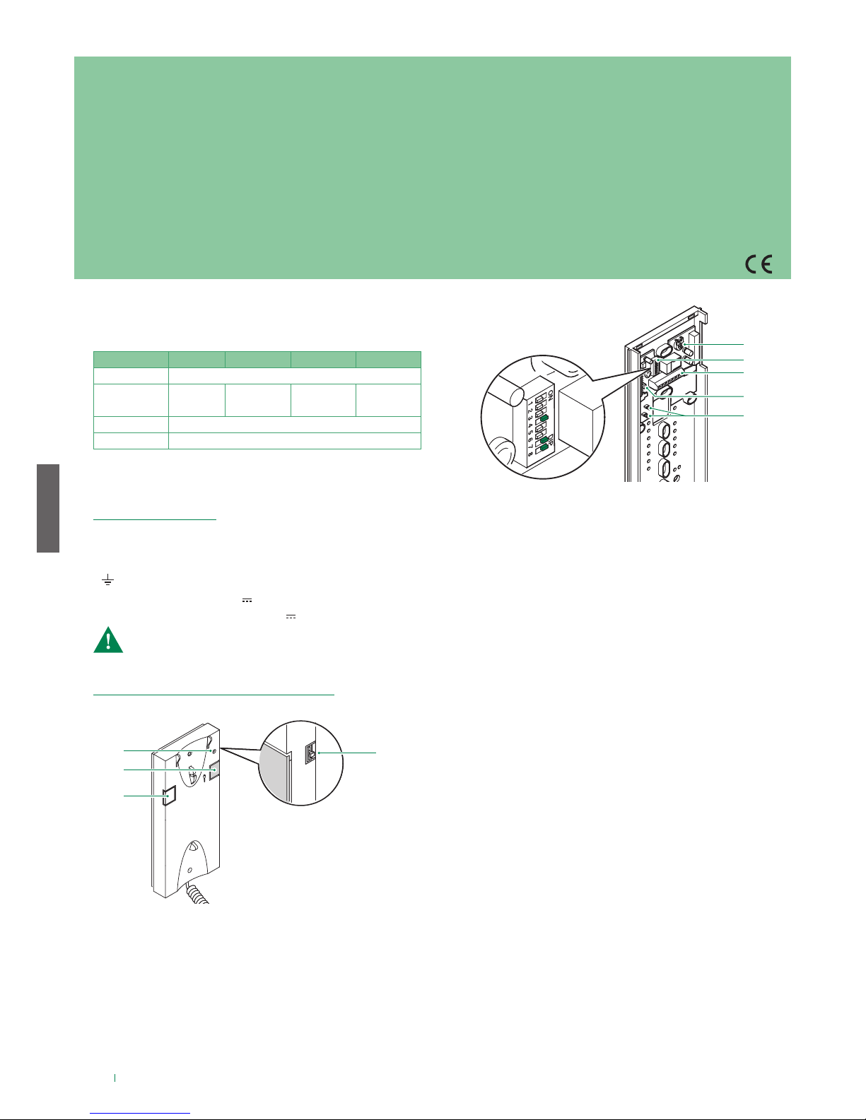
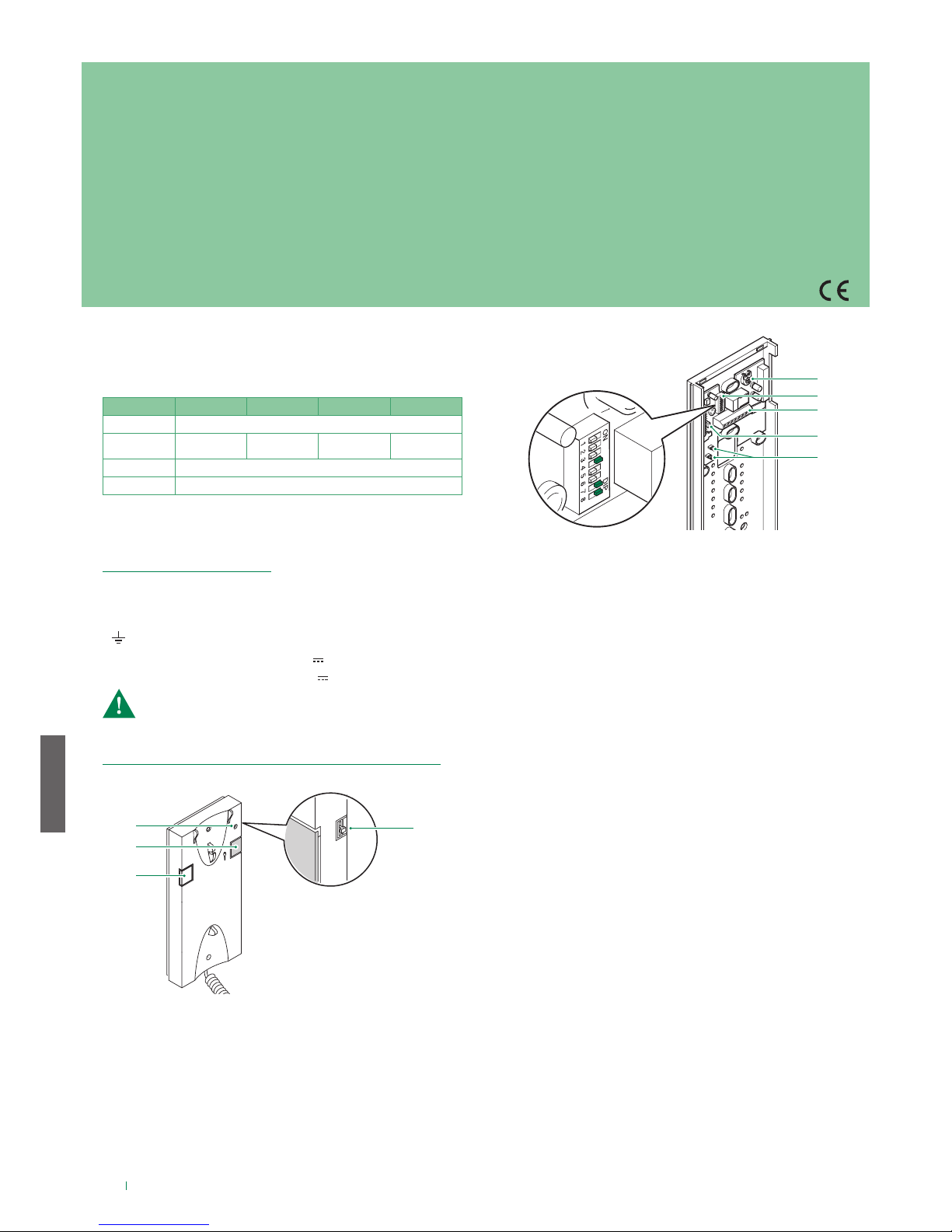
CITOFONI ADDIZIONALI
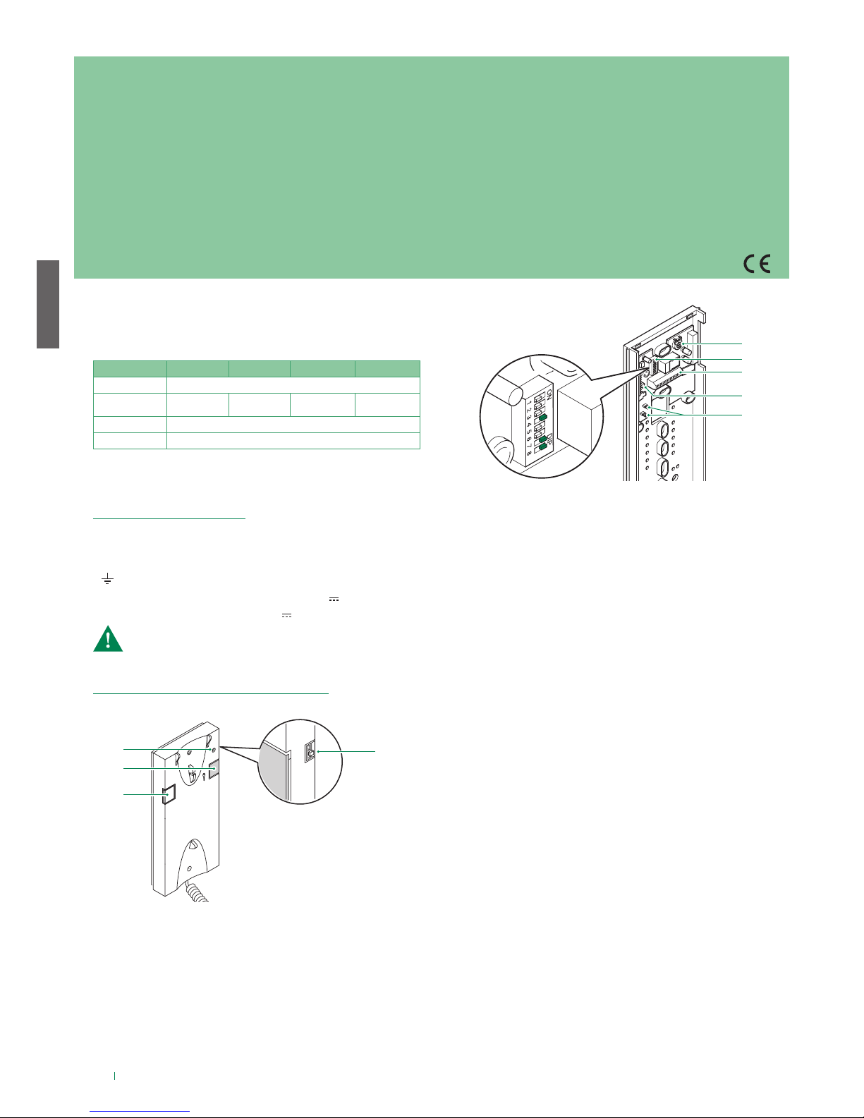
Art. 2638
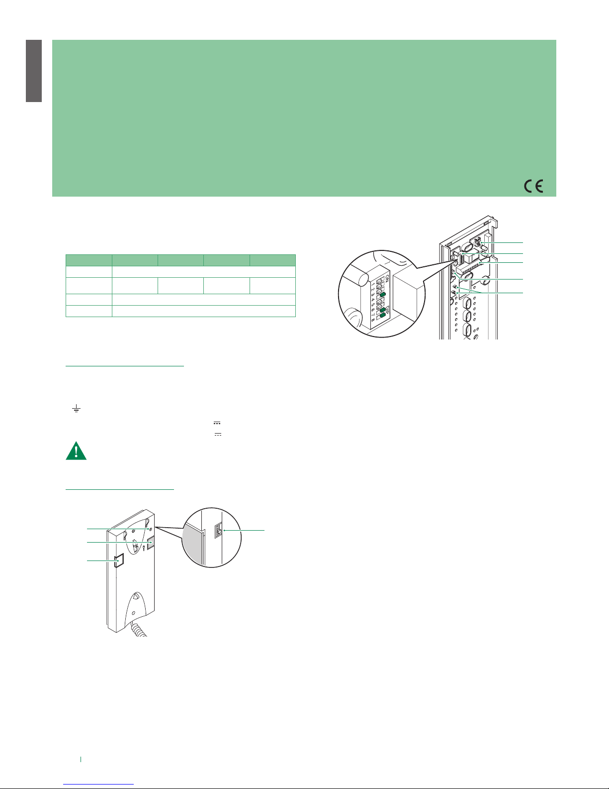
1. Indicatore funzione Privacy.
2. Pulsante apriporta.
3. Pulsante P1 attuatore generico / pulsante per usi vari presente
in morsettiera (P1 C1).
4. Selettore suoneria/servizio Privacy a 3 posizioni:
Posizione alto: Suoneria volume massimo.
Posizione centrale: Suoneria volume medio.
Posizione basso: Attivazione funzione privacy. (Per servizio
privacy si intende l’esclusione della suoneria di chiamata
dal posto esterno e centralino; l’attivazione della funzione è
evidenziata dalla comparsa di un indicatore rosso in alto a
destra).
Impostare il codice utente tramite Dip Switch U2 secondo la
corrispondenza descritta nella tabella di pag 17.
Vedi pag 16.
L L connessione alla linea bus.
CFP CFP ingresso chiamata da piano.
P1 C1 morsetti pulsante P1 C. NO. 24V 100mA dedicato a
servizi vari (rimuovere CV1 e CV2).
S+ S- morsetti per dispositivo ripetizione di chiamata.
8. JP2 jumper per selezionare la funzione Chiamata centralino
(posizione C) / Attuatore generico (posizione A) del pulsante
P1.
9. CV1 CV2 jumper da rimuovere per avere contatto pulito C. NO.
sul pulsante P1.
5. Trimmer regolazione volume microfono.
6. Dip switch U2 per impostazione codice utente.
7. Morsetti connessione impianto:
PROGRAMMAZIONE CITOFONO ART. 2638
INSTALLAZIONE CITOFONO ART. 2638
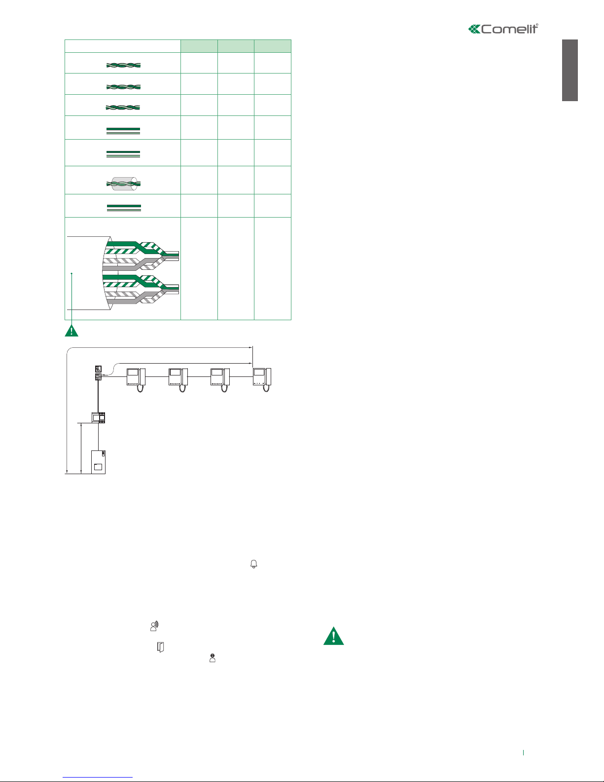
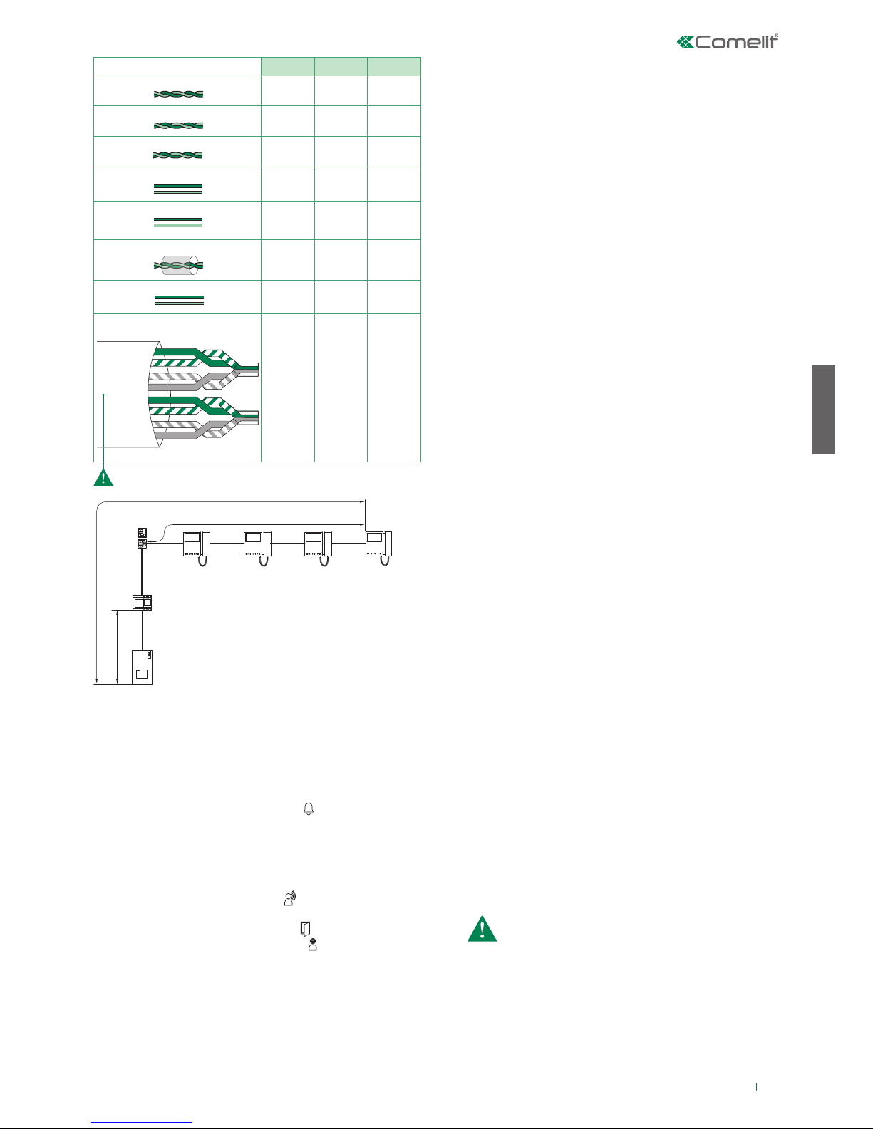
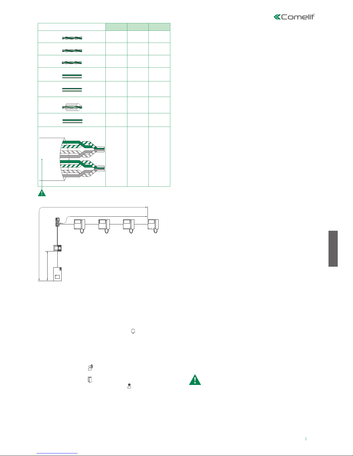
La distanza massima totale tra il posto esterno e il monitor più lontano
è 200 m (con cavo Art.4577).
La somma totale del numero di posti interni con stesso codice
utente e del numero di dispositivi di ripetizione chiamata (suoneria
supplementare) collegati ai suddetti posti interni non può superare il
numero di 4 (con max 1 posto interno principale e max 3 posti interni
sercondari). Connettere un solo dispositivo di ripetizione chiamata per
ogni posto interno.
La distanza MAX del collegamento tra posto interno e dispositivo
di ripetizione chiamata è di 20 m; utilizzare cavo schermato per il
collegamento e non far passare i cavi in prossimità di carichi induttivi
pesanti o cavi di alimentazione (230V / 400V).
ALIMENTATORE ART. 1209
Per le istruzioni di installazione e configurazione dei posti interni
(Art. 6701W, 6700W, 6701W/BM, 6700W/BM) e del posto esterno
(Art. 4893) fare riferimento ai rispettivi manuali tecnici.
Dimensioni: 108×90×62 mm (6 moduli DIN).
Protetto da cortocircuiti e sovraccarichi.
Descrizione morsettiera
L N ingresso tensione di rete 110-240 V~
L2 L2 uscita linea bus di montante (31 V )
L1 L1 ingresso linea bus principale (31 V )
I kit sono composti dai seguenti articoli:
8461M 8461MB 8461M/BM 8461MB/BM
Posto esterno Art. 4893
Posto interno
Art. 6701W Art. 6700W Art. 6701W/BM
(staa inclusa)
Art. 6700W/BM
(staa inclusa)
Alimentatore Art. 1209
Terminazione Art. 1216
Nell'impianto elettrico dell'edificio deve essere previsto un
interruttore di rete onnipolare (facilmente accessibile) con
un'apertura di contatto di almeno 3mm in grado di sezionare
l'alimentazione del dispositivo.
Page 3
3
IT
1209
4893
1214/2C
1216
B
C
A
6700W
6701W
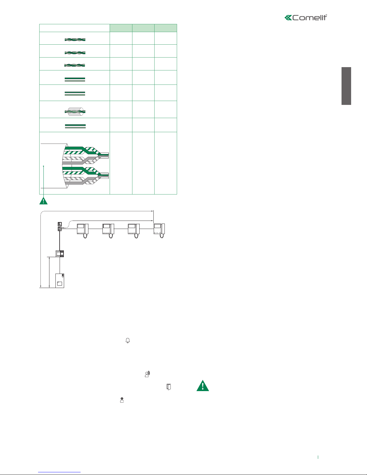
A MAX B MAX C MAX
Comelit Art.4577 1 mm2 (Ø 1,2 mm AWG 17)
200 m
(655 feet)
100 m
(330 feet)
200 m
(655 feet)
UTP5 cat. 5 0,2 mm2 (Ø 0,5 mm AWG 24)
100 m
(330 feet)
60 m
(195 feet)
100 m
(330 feet)
0,28 mm2 (Ø 0,6 mm AWG 23)
100 m
(330 feet)
60 m
(195 feet)
100 m
(330 feet)
0,5 mm2 (Ø 0,8 mm AWG 20)
100 m
(330 feet)
60 m
(195 feet)
100 m
(330 feet)
1 mm2 (Ø 1,2 mm AWG 17)
100 m
(330 feet)
60 m
(195 feet)
100 m
(330 feet)
1 mm2 (Ø 1,2 mm AWG 17)
80 m
(260 feet)
40 m
(130 feet)
80 m
(260 feet)
1,5 mm2 (Ø 1,4 mm AWG 15)
100 m
(330 feet)
60 m
(195 feet)
100 m
(330 feet)
*UTP5 cat. 5 0,2 mm2 (Ø 0,5 mm AWG 24)
MULTI PAIR CABLE
GREEN
ORANGE
BLU
GREEN / WHITE
ORANGE / WHITE
BLU / WHITE
BROWN / WHITE
BROWN
120 m
(390 feet)
70 m
(230 feet)
120 m
(390 feet)
Da posto esterno, toccare il pulsante corrispondente all'utente
che si desidera contattare per inviare la chiamata.
√ L'autoaccensione è possibile solo con impianto a riposo
Premere il tasto autoaccensione (default tasto 2) per
visualizzare sullo schermo del monitor l'immagine trasmessa
dal posto esterno.
Premere il tasto programmato per avviare la chiamata
Per terminare la chiamata in corso e mettersi in comunicazione
con il posto esterno occorre riagganciare la cornetta e
sollevarla novamente (oppure premere 2 volte il tasto fonica).
Questa funzione permette di inviare una chiamata agli altri
apparecchi (videocitofoni e/o citofoni) impostati sullo stesso
indirizzo di chiamata (per la programmazione vedi il manuale
tecnico del rispettivo posto interno).
Questa funzione permette di chiamare specifici posti interni (per
la programmazione vedi il manuale tecnico del rispettivo posto
interno).
Una chiamata da posto esterno è prioritaria rispetto a una
comunicazione intercomunicante. In questo caso gli utenti che si
trovano già in conversazione sentiranno un tono simile a quello di
chiamata se quest'ultima è indirizzata a loro o un triplice tono di
segnalazione in caso contrario e acquisiranno il video del posto
esterno chiamante (in caso di monitor principali).
» Se l’impianto è libero: il ricevente della chiamata alzando
la cornetta (o premendo il tasto "presa
fonica") entrerà in comunicazione
con il chiamante. Agganciando la
cornetta (o ripremendo il tasto fonica)
la comunicazione verrà terminata.
» Se l’impianto è occupato: il led di segnalazione lampeggerà
per alcuni secondi (per monitor
Mini il led privacy lampeggerà 4
volte).
» Se l’impianto è libero: Sul posto esterno si accende il led
per l’illuminazione del soggetto chiamante, il led lampeggia
e si avverte un suono di conferma. Sui monitor interno/i
principale/i appare automaticamente l’immagine da posto
esterno. Su monitor secondari è possibile richiedere il video
(senza rispondere alla chiamata) toccando il tasto 2 (di default
programmato per l’autoaccensione).
» Se l’utente risponde alla chiamata: sul posto esterno si
accende il led .
» Se l’utente preme il comando apriporta: sul posto esterno
si accende il led .
» Se l’impianto è occupato: il led lampeggia e il posto
esterno emette un tono di impianto occupato.
Eettuare una chiamata da posto esterno
Autoaccensione
CHIAMATA GENERALE INTERNA
INTERCOMUNICANTE SELETTIVO
Funzionamento con posti interni supplementari
Quando dal posto esterno si effettua una chiamata, il monitor
che si accende è il videocitofono principale. Gli eventuali monitor
secondari della medesima unità familiare resteranno spenti.
Rispondendo alla chiamata del posto esterno da un videocitofono
secondario, l'immagine viene automaticamente visualizzata sul
monitor (e il monitor del videocitofono principale si spegne).
Per visualizzare l’immagine senza attivare la fonica con il posto
esterno, premere il pulsante 2- autoaccensione/richiesta video.
Funzionamento
Il kit può gestire fino a un massimo di 4 videocitofoni o citofoni per
pulsante di chiamata di cui max 1 videocitofono principale.
MONITOR PRINCIPALI / SECONDARI
Funzionamento con posti esterni supplementari
FUNZIONAMENTO CON SCAMBIO ART. 1404 (DEFAULT)
Consultare il manuale tecnico del posto esterno Art. 4893 per la
programmazione delle funzioni speciali
:
Nella configurazione dell'Art. 1404, i Dip switch MIN e MAX
definiscono rispettivamente i codici utente più basso e più alto
collegabili al montante. Per l’impostazione dei valori desiderati
si faccia riferimento alla tabella di pag. 17. Scambi relativi a
montanti distinti devono gestire intervalli di codici non sovrapposti.
La funzione autoaccensione è disponibile solo per impianti come da
schema MNK/017CQC (per ogni posto interno è possibile effettuare
la bascula tra il posto esterno del kit e il posto esterno principale).
• Posto esterno (Porter) con scambio (secondario): funzione
di default da utilizzare anche in impianti con scambio Art. 1404
(per l'installazione di 3 o più ingressi)
• Posto esterno (Porter) Secondario: funzione da utilizzare in
impianti con scambio Art. 1405 e 2 posti esterni
• Posto esterno (Porter) Principale: funzione da utilizzare in
impianti con scambio Art. 1405 e 2 posti esterni
FUNZIONAMENTO CON SCAMBIO ART. 1405
Con scambio Art. 1405 è possibile installare solo 1 posto
esterno principale e 1 posto esterno secondario.
In modalità “Posto esterno Principale” i comandi apriporta
(attuatore) vengono eseguiti solo se il posto esterno è in stato di
chiamata o autoaccensione. La funzionalità door-open è sempre
disattiva.
In modalità “Posto esterno Secondario” i comandi apriporta (o
attuatore) vengono eseguiti se l’impianto è a riposo o se il posto
esterno è attivo.
Con impianto a riposo il primo comando autoaccensione
attiva la telecamera del posto esterno secondario. Ulteriori
comandi eseguono la bascula tra i due posti esterni attivando
alternativamente il posto esterno principale e secondario.
Cavo UTP con connessione multi-coppiola: RISPETTARE I COLORI INDICATI IN FIGURA!
Page 4
4
EN
1
2
3
4
5
6
7
8
9
Warning
• Install the equipment by carefully following the instructions given by the manufacturer and in compliance with the standards in force. Do not tamper with the internal
elements offering protection against short circuits and overcurrents.
• All the equipment must only be used for the purpose it was designed for. Comelit Group S.p.A. declines any responsibility for improper use of the apparatus, for any
alterations made by others for any reason or for the use of non-original accessories or materials.
• All the products comply with the requirements of Directive 2006/95/EC (which replaces Directive 73/23/EEC and subsequent amendments), as certified by the CE mark
they carry.
• Do not route the riser wires in proximity to power supply cables (230/400V).
• Do not insert objects or pour liquids into the device.
• Installation, mounting and assistance procedures for electrical devices must only be performed by specialised electricians.
• Cut off the power supply before carrying out any maintenance work.
• Do not press and hold the audio hook while the handset is lifted.
• The camera must not be installed opposite bright light sources, or in places where the filmed subject is against the light. To resolve the above problem, we recommend
modifying the installation height of the camera, which is usually 160 - 165 cm, to a height of 180 cm and pointing the lens downward so as to improve filming quality.
• Cameras with colour CCD sensor have poorer sensitivity in low light conditions than black/white cameras. We therefore recommend, in dimly lit environments, to
install an additional light source
• IMPORTANT: to prevent a malfunction of the device, make sure that the metal fascia of art. 4893 does not rub against any other metal parts and damage their
insulation.
General information
Operating distances
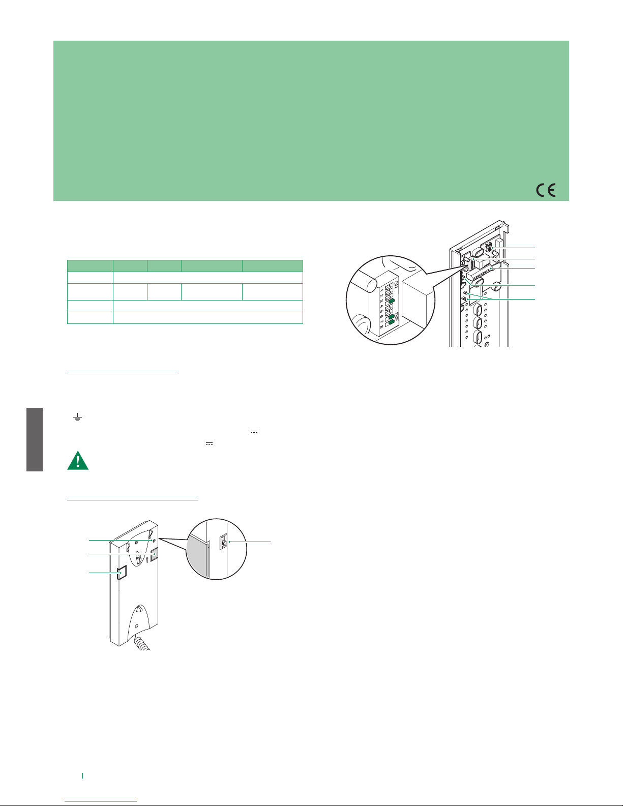
ADDITIONAL DOOR-ENTRY PHONES
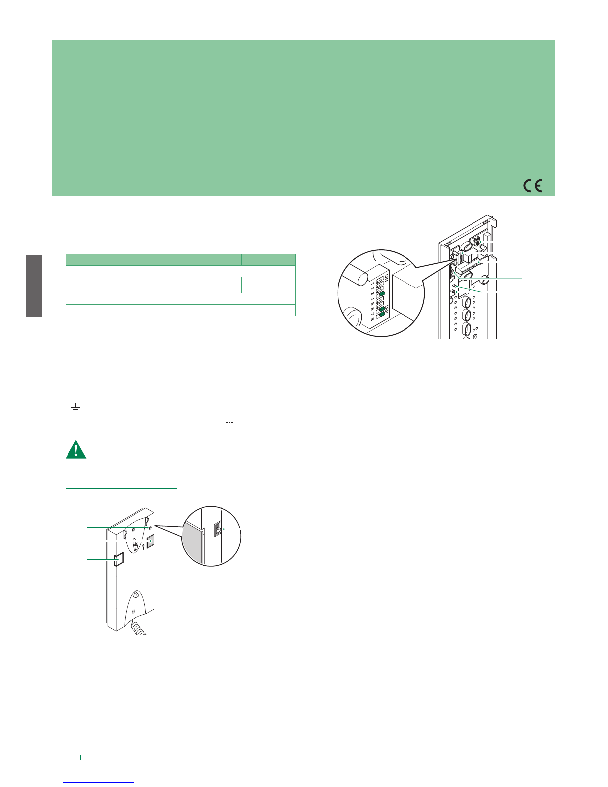
Art. 2638
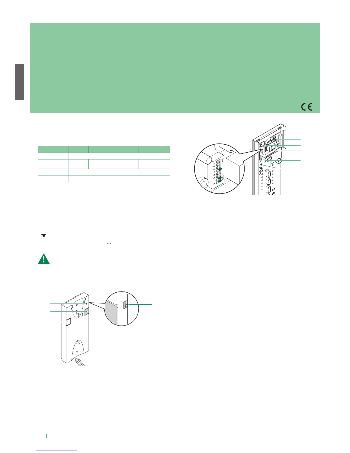
1. Privacy function indicator.
2. Key button.
3. Button P1 generic actuator / button for various uses present
on terminal block (P1 C1).
4. 3-position ringtone/Privacy service selector:
High position: Maximum ringtone volume.
Middle position: Medium ringtone volume.
Low position: Privacy service activation. (Privacy service
means exclusion of the call ringtone from the external unit and
switchboard; activation of the Privacy function is signalled by a
red indicator appearing at the top right-hand side).
Set the user code on Dip Switches U2 as indicated in the table
on page 17.
See page 16.
L L bus line connection.
CFP CFP Floor door call input.
P1 C1 terminals for pushbutton P1 C.NO. 24V 100mA
dedicated to various services (remove CV1 and CV2).
S+ S- terminals for call repetition device.
8. JP2 jumper for selecting the Switchboard call (position C) /
Generic actuator (position A) function of button P1.
9. CV1 CV2 jumpers to be removed in order to obtain a voltage
free C. NO contact on button P1.
5. Trimmer for adjusting the microphone volume.
6. U2 DIP switch for setting user code.
7. System connection terminals:
PROGRAMMING OF DOOR-ENTRY PHONE ART. 2638
INSTALLATION OF DOOR-ENTRY PHONE ART. 2638
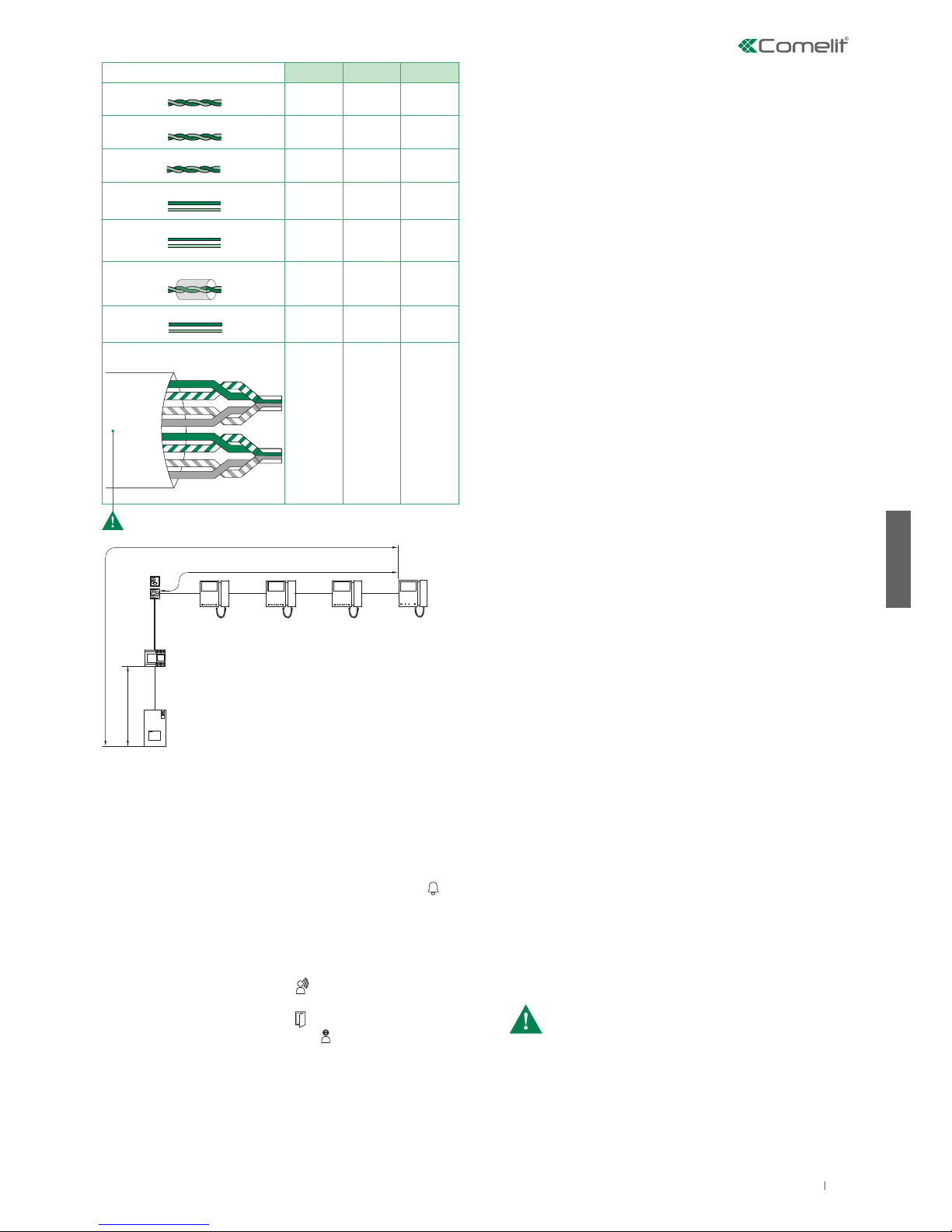
The maximum total distance between the external unit and the furthest
monitor is 200 m (with cable Art. 4577).
The total number of internal units with the same user code and call
repetition devices (additional ringtone) connected to these internal
units cannot exceed 4 (with a maximum of 1 main internal unit and 3
secondary internal units). Connect only one call repetition device for
each internal unit.
The maximum cable length between the internal unit and call repetition
device is 20 m. A shielded cable should be used for the connection
and should not run close to heavy inductive loads or power supply
cables (230 V / 400 V).
POWER SUPPLY UNIT ART. 1209
For instructions on the installation and configuration of internal
units (Art. 6701W, 6700W, 6701W/BM, 6700W/BM) and the external unit (Art. 4893), refer to the respective technical manuals.
Dimensions: 108×90×62 mm (6 DIN modules).
Protected from short-circuits and overloads.
Description of terminal block
L N mains power input 110-240 V~
L2 L2 riser bus line output (31 V )
L1 L1 main bus line input (31 V )
The kits are comprised of the following articles:
8461M 8461MB 8461M/BM 8461MB/BM
External unit Art. 4893
Internal unit
Art. 6701W Art. 6700W Art. 6701W/BM
(backplate included)
Art. 6700W/BM
(backplate included)
Power supply unit Art. 1209
Termination Art. 1216
The electrical system of the building must be fitted with an (easily
accessible) omnipolar mains switch with a contact opening of at
least 3 mm, which is capable of cutting o the power supply of
the device.
Page 5
5
EN
1209
4893
1214/2C
1216
B
C
A
6700W
6701W
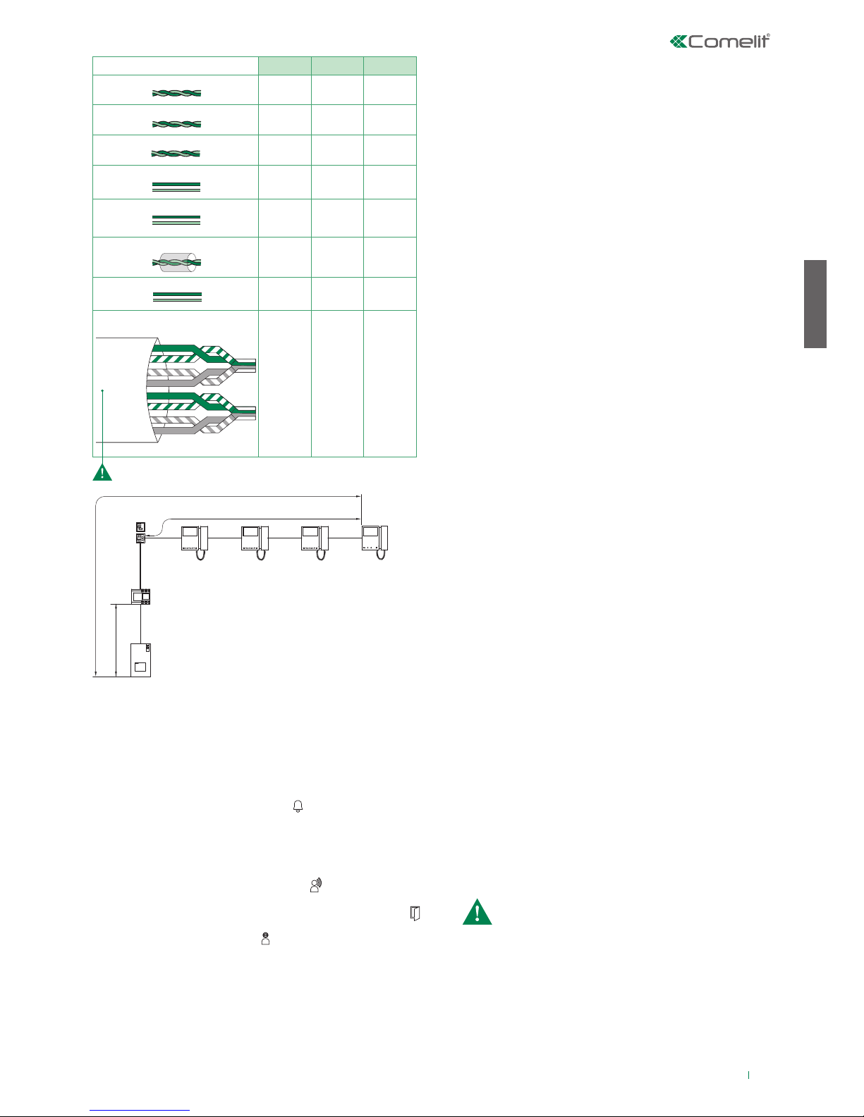
A MAX B MAX C MAX
Comelit Art.4577 1 mm2 (Ø 1,2 mm AWG 17)
200 m
(655 feet)
100 m
(330 feet)
200 m
(655 feet)
UTP5 cat. 5 0,2 mm2 (Ø 0,5 mm AWG 24)
100 m
(330 feet)
60 m
(195 feet)
100 m
(330 feet)
0,28 mm2 (Ø 0,6 mm AWG 23)
100 m
(330 feet)
60 m
(195 feet)
100 m
(330 feet)
0,5 mm2 (Ø 0,8 mm AWG 20)
100 m
(330 feet)
60 m
(195 feet)
100 m
(330 feet)
1 mm2 (Ø 1,2 mm AWG 17)
100 m
(330 feet)
60 m
(195 feet)
100 m
(330 feet)
1 mm2 (Ø 1,2 mm AWG 17)
80 m
(260 feet)
40 m
(130 feet)
80 m
(260 feet)
1,5 mm2 (Ø 1,4 mm AWG 15)
100 m
(330 feet)
60 m
(195 feet)
100 m
(330 feet)
*UTP5 cat. 5 0,2 mm2 (Ø 0,5 mm AWG 24)
MULTI PAIR CABLE
GREEN
ORANGE
BLU
GREEN / WHITE
ORANGE / WHITE
BLU / WHITE
BROWN / WHITE
BROWN
120 m
(390 feet)
70 m
(230 feet)
120 m
(390 feet)
To send the call from an external unit, touch the button
corresponding to the user you want to contact.
√ Self-ignition is possible only when the system is in standby
Press the self-ignition button (button 2 by default) to display
on the monitor the image transmitted from the external unit.
Press the programmed button to send the call
To terminate the call in progress and enter into communication
with the external unit, hang up and then lift the handset again
(or press the audio button 2 times).
This function can be used to transmit a call to the other units
(door entry monitors and/or door-entry phones) set to the same
call address (for programming, refer to the technical manual for
the respective internal unit).
This function enables the user to call specific internal units (for
programming see the technical manual of the respective internal
unit).
A call from the external unit always takes priority over an intercom
communication. In this case, users who are already speaking
will hear a tone similar to the ringtone, if the call is addressed to
them, or otherwise a triple signalling tone will sound and the video
image from the external unit from which the call was made will
appear (in the case of a main monitor).
» If the system is not busy:
the receiver of the call can lift the handset (or press the audio
button) to enter into communication with the caller. The
communication is terminated by replacing the handset (or by
pressing the audio button again).
» If the system is busy: the LED indicator light will flash for
a few seconds (on Mini monitors the
privacy LED will flash 4 times).
» If the system is not busy: On the external unit the caller
illumination LED will light up, the LED will flash and the
confirmation tone will sound. The video image from the external
unit will appear automatically on the main internal monitor/s.
The video image can be displayed on secondary monitors
(without answering the call) by pressing button 2 (programmed
by default for the self-ignition function).
» If the user responds to the call: the LED will illuminate
on the external unit.
» If the user presses the lock-release control: the LED will
illuminate on the external unit.
» If the system is busy: the LED will flash and the external
unit will emit the system busy tone.
To make a call from an external unit
Self-ignition
GENERAL INTERNAL CALL
SELECTIVE INTERCOM
Operation with additional internal units
When a call is made from the external unit, the monitor switched
on will be the main door entry monitor. Any other secondary
monitors in the same family unit will remain off.
When responding to a call from the external unit using a secondary
door entry monitor, the image is automatically displayed on the
monitor (and the main door entry monitor is switched off).
To display the image without activating audio communication
with the external unit, press button 2 -self-ignition/video request.
Operation
The kit can manage up to a maximum of 4 door entry monitors or
door-entry phones for each call button, including a maximum of 1
main door entry monitor.
MAIN/SECONDARY MONITORS
Operation with additional external units
OPERATION WITH SWITCHING DEVICE ART. 1404 (DEFAULT)
Refer to the technical manual for the external unitArt. 4893 for the
programming of special functions
:
In the configuration of Art. 1404, the MIN and MAX Dip switches
define respectively the lowest and highest user codes which can
be connected to the riser. For information on setting the desired
values, refer to the table on page 17. Separate switching
devices for different risers must manage code ranges which are
not overlapping. The self-ignition function is only available for
systems as depicted in diagram MNK/017CQC (for each internal
unit, it is possible to toggle between the external unit of the lit and
the main external unit).
• External unit (Porter) with switching (secondary): default
function to be used also in systems with switching device Art.
1404 (for installations with 3 or more entrances)
• Secondary external unit (Porter): function to be used in
systems with switching device Art. 1405 and 2 external units
• Main external unit (Porter): function to be used in systems
with switching device Art. 1405 and 2 external units
OPERATION WITH SWITCHING DEVICE ART. 1405
With the switching device Art. 1405 it is possible to install only
1 main external unit and 1 secondary external unit.
In “Main external unit” mode, lock release (or actuator)
commands are only executed if the external unit is in call or selfignition mode. The "door-open" function is always deactivated.
In “Secondary external unit” mode, lock release (or actuator)
commands are executed if the system is in standby mode or if the
external unit is active.
If the system is in standby mode the first self-ignition command
will activate the camera of the secondary external unit. Further
commands will toggle between the external units, activating
alternately the main external unit and the secondary external unit.
UTP cable with multi-cable connection: FOLLOW THE COLOURS SHOWN IN THE DIAGRAM!
Page 6
6
FR
1
2
3
4
5
6
7
8
9
Avertissement
• Effectuer l'installation en suivant scrupuleusement les instructions fournies par le constructeur et conformément aux normes en vigueur. Ne pas toucher les protections internes contre les
courts-circuits et les surcharges.
• Tous les appareils doivent être strictement destinés à l'emploi pour lequel ils ont été conçus. La société Comelit Group S.p.A. décline toute responsabilité en cas de mauvais usage des
appareils, pour des modifications effectuées par d’autres personnes pour n’importe quelle raison et pour l'utilisation d’accessoires et matériaux non d'origine.
• Tous les produits sont conformes aux prescriptions de la directive 2006/95/CE (qui remplace la directive 73/23/CEE et amendements successifs). L'application du marquage CE atteste
cette conformité.
• Éviter de placer les fils de montant à proximité des câbles d'alimentation (230/400V).
• Ne jamais introduire d'objets ni verser de liquides à l'intérieur du dispositif.
• Les interventions d'installation, de montage et d'assistance aux appareils électriques sont réservées à des électriciens spécialisés.
• Couper l'alimentation avant d'effectuer toute opération d'entretien.
• Ne pas maintenir le crochet phonie enfoncé lorsque le combiné est décroché.
• La caméra ne doit pas être installée face à de fortes sources de lumière ni dans des lieux où la personne filmée est fortement à contre-jour. Pour résoudre le problème précédemment
décrit, il est conseillé de modifier la hauteur d'installation de la caméra, normalement à 160 - 165 cm, en la plaçant à une hauteur de 180 cm et d'orienter l'objectif vers le bas de manière
à améliorer la qualité des prises de vue.
• Les caméras avec capteur CCD couleurs présentent, dans des conditions de mauvaise luminosité, une sensibilité inférieure par rapport aux caméras en noir et blanc. Par
conséquent, dans les milieux faiblement éclairés, il est conseillé de prévoir une source d'éclairage supplémentaire.
• IMPORTANT : pour ne pas compromettre le fonctionnement du dispositif, s'assurer que la façade en métal de l'article 4893 n'entre pas en contact avec d'autres parties métalliques,
ce qui risquerait d'endommager son revêtement isolant.
Généralités
Distances de fonctionnement
COMBINÉS AUDIO SUPPLÉMENTAIRES
Art. 2638
1.
Voyant fonction Privacy.
2.
Bouton ouvre-porte.
3.
Bouton P1 actionneur générique / bouton pour usages divers
présent sur le bornier (P1 C1).
4.
Sélecteur sonnerie/service Privé à 3 positions :
Position haute : Sonnerie volume maximum.
Position centrale : Sonnerie volume moyen.
Position basse : Activation fonction Privacy. (Le service privacy
exclut l’appel du poste extérieur ou du standard de conciergerie;
l'activation de la fonction est indiquée par l'apparition d'un voyant
rouge en haut à droite).
Régler le code d'appel à l'aide du dip switch U2 en respectant les
indications du tableau page 17.
Voir page 16.
L L connexion à la ligne bus.
CFP CFP entrée appel porte palière.
P1 C1 bornes bouton P1 C NO. 24V 100mA dédié aux services
divers (enlever CV1 et CV2).
S+ S- bornes pour le dispositif de répétition de l'appel.
8.
JP2 cavalier pour sélectionner la fonction Appel standard (position
C)/ Actionneur générique (position A) du bouton P1.
9.
CV1 CV2 cavalier à retirer pour disposer du bouton P1 C. NO.
5.
Potentiomètre de réglage du volume du microphone.
6.
Dip switch U2 pour la programmation du code d'appel.
7.
Bornes pour le raccordement de l'installation :
PROGRAMMATION COMBINÉ AUDIO ART. 2638
INSTALLATION COMBINÉ AUDIO ART. 2638
La distance maximum totale entre le poste extérieur et le moniteur le plus
éloigné est de 200 m (avec le câble Art.4577).
La somme des postes intérieurs ayant le même code d'appel et des
dispositifs de répétition d'appel (sonnerie supplémentaire) branchés à ces
postes intérieurs ne peut pas être supérieure à 4 (avec au maximum 1 poste
intérieur principal et 3 postes intérieurs secondaires). Brancher un seul
dispositif de répétition d'appel pour chaque poste intérieur.
La distance MAX de la connexion entre le poste intérieur et le dispositif de
répétition d'appel est de 20 m; pour la connexion, utiliser un câble blindé et
ne pas faire passer les câbles à proximité de charges inductives lourdes ou
de câbles d'alimentation (230V / 400V).
ALIMENTATION ART. 1209
Pour les instructions d'installation et de configuration des postes
intérieurs (Art. 6701W, 6700W, 6701W/BM, 6700W/BM) et du poste extérieur (Art. 4893), consulter les manuels techniques correspondants.
Dimensions : 108×90×62 mm (6 modules DIN).
Protégé contre les courts-circuits et les surcharges.
Description bornier
L N entrée tension de ligne 110-240 V~
L2 L2 sortie ligne bus de colonne montante (31 V )
L1 L1 entrée ligne bus principale (31 V )
Les kits comprennent les articles suivants :
8461M 8461MB 8461M/BM 8461MB/BM
Poste extérieur Art. 4893
Poste intérieur
Art. 6701W Art. 6700W Art. 6701W/BM
(étrier inclus)
Art. 6700W/BM
(étrier inclus)
Alimentation Art. 1209
Terminaison Art. 1216
L'installation électrique du bâtiment doit être munie d'un interrupteur
de réseau omnipolaire (facilement accessible) avec une ouverture de
contact d'au moins 3 mm en mesure de sectionner l'alimentation du
dispositif.
Page 7
7
FR
1209
4893
1214/2C
1216
B
C
A
6700W
6701W
A MAX B MAX C MAX
Comelit Art.4577 1 mm2 (Ø 1,2 mm AWG 17)
200 m
(655 feet)
100 m
(330 feet)
200 m
(655 feet)
UTP5 cat. 5 0,2 mm2 (Ø 0,5 mm AWG 24)
100 m
(330 feet)
60 m
(195 feet)
100 m
(330 feet)
0,28 mm2 (Ø 0,6 mm AWG 23)
100 m
(330 feet)
60 m
(195 feet)
100 m
(330 feet)
0,5 mm2 (Ø 0,8 mm AWG 20)
100 m
(330 feet)
60 m
(195 feet)
100 m
(330 feet)
1 mm2 (Ø 1,2 mm AWG 17)
100 m
(330 feet)
60 m
(195 feet)
100 m
(330 feet)
1 mm2 (Ø 1,2 mm AWG 17)
80 m
(260 feet)
40 m
(130 feet)
80 m
(260 feet)
1,5 mm2 (Ø 1,4 mm AWG 15)
100 m
(330 feet)
60 m
(195 feet)
100 m
(330 feet)
*UTP5 cat. 5 0,2 mm2 (Ø 0,5 mm AWG 24)
MULTI PAIR CABLE
GREEN
ORANGE
BLU
GREEN / WHITE
ORANGE / WHITE
BLU / WHITE
BROWN / WHITE
BROWN
120 m
(390 feet)
70 m
(230 feet)
120 m
(390 feet)
Appuyer sur le bouton correspondant au résident à contacter pour
effectuer l'appel.
√ L'auto-allumage n'est possible que lorsque l'installation est en veille.
Appuyer sur la touche auto-allumage (touche 2 par défaut) pour
afficher sur le moniteur l'image provenant du poste extérieur.
Appuyer sur la touche prédéfinie pour envoyer l'appel
Pour conclure l'appel en cours et entrer en communication avec le
poste extérieur, raccrocher puis resoulever le combiné (ou appuyer
2 fois sur la touche phonie).
Cette fonction permet d'envoyer un appel aux autres appareils
(moniteurs vidéophoniques et/ou combinés audio) programmés
sur la même adresse d'appel (pour la programmation, consulter le
manuel technique du poste intérieur correspondant).
Cette fonction permet d'appeler des postes intérieurs spécifiques
(pour la programmation, consulter le manuel technique de chaque
poste intérieur).
Un appel provenant d'un poste extérieur a la priorité sur une
communication intercommunicante. Dans ce cas, les utilisateurs en
communication entendront dans le combiné un signal sonore similaire à
un signal d'appel si ce dernier leur est destiné, ou un triple signal sonore
dans le cas contraire, et ils recevront l'image relative à l'appel provenant
de la platine extérieure (en présence de moniteurs principaux).
» Si la ligne est libre : en soulevant le combiné (ou en appuyant
sur la touche « prise phonie »), la personne
recevant l'appel entre en communication
avec l'appelant. En reposant le combiné
(ou en rappuyant sur la touche phonie), la
communication est interrompue.
» Si la ligne est occupée : la led de signalisation clignote quelques
secondes (pour les moniteurs Mini, la led
privacy clignote 4 fois).
» Si la ligne est libre : La led permettant d'éclairer l'appelant
s'allume sur le poste extérieur, la led clignote et une tonalité de
confirmation retentit. Le moniteur du/des poste(s) intérieur(s)/du/des
poste(s) principal/aux ache automatiquement l'image provenant
du poste extérieur. Il est possible de demander la vidéo sur les
moniteurs secondaires (sans répondre à l'appel), en appuyant sur la
touche 2 (prédéfinie pour l'auto-allumage).
» Si l’usager répond à l'appel : la led s'allume sur le poste
extérieur.
» Si l’usager appuie sur la commande ouvre-porte : la led
s'allume sur le poste extérieur.
» Si la ligne est occupée : la led clignote et le poste extérieur émet
la tonalité de ligne occupée.
Eectuer un appel à partir du poste extérieur
Auto-allumage
APPEL GÉNÉRAL INTERNE
APPEL INTERCOMMUNICANT SÉLECTIF
Fonctionnement avec postes intérieurs supplémentaires
Lorsque l'on effectue un appel depuis le poste extérieur, c'est le
moniteur principal qui s'allume. Les autres moniteurs secondaires de la
même unité familiale resteront éteints.
En répondant à l'appel du poste extérieur depuis un moniteur
vidéophonique secondaire, l'image est automatiquement visualisée sur
ce moniteur (et le moniteur principal s'éteint).
Pour visualiser l'image sans activer la phonie avec le poste
extérieur, appuyer sur le bouton 2 - auto-allumage/appel vidéo.
Fonctionnement
Le kit peut gérer jusqu'à un maximum de 4 moniteurs
vidéophoniques ou combinés audio par bouton d'appel, avec au
maximum 1 moniteur vidéophonique principal.
MONITEURS PRINCIPAUX / SECONDAIRES
Fonctionnement avec postes extérieurs supplémentaires
FONCTIONNEMENT AVEC COMMUTATEUR ART. 1404 (PAR DÉFAUT)
Consulter le manuel technique du poste extérieur Art. 4893 pour la
programmation des fonctions spéciales :
Dans la configuration de l'art. 1404, les dip switches MIN et MAX
définissent respectivement le code usager le plus bas et le code
usager le plus haut pouvant être branchés à la colonne montante. Pour
programmer les valeurs désirées, se référer au tableau de la page 17.
Les commutateurs correspondant à des colonnes montantes distinctes
doivent gérer des intervalles de codes non superposés. La fonction autoallumage est disponible uniquement sur les installations correspondant
au schéma MNK/017CQC (il est possible de basculer le poste extérieur
du kit avec le poste extérieur principal pour chaque poste intérieur).
• Poste extérieur (HP) avec commutateur (secondaire) : fonction
par défaut, à utiliser également sur les installations disposant du
commutateur Art. 1404 (pour l'installation d'au moins 3 entrées)
• Poste extérieur (HP) secondaire : fonction à utiliser sur des installations
disposant du commutateur Art. 1405 et de 2 postes extérieurs
• Poste extérieur (HP) principal : fonction à utiliser sur des installations
disposant du commutateur Art. 1405 et de 2 postes extérieurs
FONCTIONNEMENT AVEC COMMUTATEUR ART. 1405
En présence du commutateur Art. 1405, il est possible d'installer
seulement 1 poste extérieur principal et 1 poste extérieur secondaire.
En mode « Poste extérieur principal », les commandes ouvre-porte
(actionneur) répondent uniquement si le poste extérieur est en condition
d'appel ou d'auto-allumage. La fonction ouvre-porte est toujours
désactivée.
En mode « Poste extérieur secondaire », les commandes ouvre-porte
(ou actionneur) répondent si l’installation est au repos ou si le poste
extérieur est activé.
Si l'installation est au repos, la première commande d'auto-allumage
allume la caméra du poste extérieur secondaire. Les commandes
suivantes passent du poste extérieur principal au poste extérieur
secondaire.
Câble UTP avec connexion paires torsadées multiples: RESPECTER LES COULEURS INDIQUÉES DANS
LA FIGURE!
Page 8
8
NL
1
2
3
4
5
6
7
8
9
Waarschuwingen
• Voer de installatiewerkzaamheden zorgvuldig uit volgens de door de fabrikant geleverde instructies en met inachtneming van de geldende normen. De interne beveiligingen tegen
kortsluiting en overstroom niet forceren.
• Alle apparaten mogen alleen gebruikt worden voor het beoogde doel waarvoor ze zijn ontworpen. Comelit Group S.p.A. is niet verantwoordelijk voor oneigenlijk gebruik van de
apparatuur, voor wijzigingen die om welke reden dan ook door derden zijn aangebracht, en voor het gebruik van accessoires en materialen die niet door de fabrikant zijn aangeleverd.
• Alle producten voldoen aan de eisen van de richtlijn 2006/95/EG (die de richtlijn 73/23/EEG en latere wijzigingen vervangt). Dit wordt bevestigd door de CE-markering op de producten.
• Monteer de draden van de stamleiding niet in de buurt van voedingskabels (230/400V).
• Voorkom het binnendringen van vreemde voorwerpen of vloeistoffen in het toestel.
• De installatie-, montage- en servicewerkzaamheden aan de elektrische apparaten mogen uitsluitend door gespecialiseerde elektriciens worden verricht.
• Sluit de voeding af voordat u onderhoudswerkzaamheden uitvoert.
• Houd de telefoonhaak niet ingedrukt als de hoorn is opgenomen.
• Installeer de camera niet tegenover felle lichtbronnen of op plaatsen waar de geregistreerde persoon met de rug naar het licht staat. Om het hierboven beschreven probleem op te
lossen, is het raadzaam de installatiehoogte van de camera, die normaal 160 - 165 cm bedraagt, te wijzigen naar een hoogte van 180 cm en om de lens naar beneden te richten, om
de opnamekwaliteit te verbeteren.
• Camera's met CCD-kleurensensor hebben in schaars verlichte omstandigheden een lagere gevoeligheid dan zwart-witcamera's. Het is daarom raadzaam om in schaars
verlichte omgevingen een extra lichtbron te plaatsen.
• BELANGRIJK: om de werking van het toestel niet in gevaar te brengen, dient u ervoor te zorgen dat het metalen frontpaneel, art. 4893, niet over de andere metalen onderdelen
schuurt en daarmee de isolerende bekleding beschadigt.
Algemene kenmerken
Afstanden
EXTRA DEURTELEFOONS
Art. 2638
1. Indicatielampje voor privacyfunctie.
2. Bedieningsknop deuropener.
3. Drukknop P1 algemene relaissturing / drukknop voor verschillende
functies in aansluitblok (P1 C1).
4. Keuzeschakelaar oproeptoon/privacyfunctie met 3 standen:
Bovenste stand: luide oproeptoon.
Middelste stand: normale oproeptoon.
Onderste stand: inschakeling privacyfunctie. (Wanneer de
privacyfunctie actief is, wordt de oproeptoon vanaf het deurstation
of vanaf de centrale uitgeschakeld. Wanneer deze functie actief is,
brandt er een rood indicatielampje rechtsboven).
Stel de gebruikerscode in via dipswitch U2 volgens de volgorde in
de tabel op pag 17.
Zie pag 16.
L L aansluiting op de busleiding.
CFP CFP aansluiting voor etagebel.
P1 C1 klemmen voor drukknop P1 NO contact. 24V 100mA voor
verschillende functies (verwijder CV1 en CV2).
S+ S- klemmen voor aansluiting van extra bel.
8. JP2 jumper voor het selecteren van de functie Oproep naar
portiercentrale (positie C) / Algemene relaissturing (positie A) van
de drukknop P1.
9. CV1 CV2 te verwijderen jumper voor het verkrijgen van een NO
droog contact op drukknop P1.
5. Trimmer volumeregeling microfoon.
6. Dipswitch U2 voor de instelling van de gebruikerscode.
7. Aansluitklemmen voor de installatie:
PROGRAMMERING DEURTELEFOON ART. 2638
INSTALLATIE DEURTELEFOON ART. 2638
De maximale afstand tussen het deurstation en de verst gelegen monitor is
200 m (met kabel Art.4577).
Het totale aantal binnentoestellen met dezelfde gebruikerscode en het
aantal extra bellen dat met deze binnentoestellen verbonden is, mag niet
meer bedragen dan 4 (met maximaal 1 hoofdbinnentoestel en maximaal
3 secundaire binnentoestellen). Sluit één extra bel aan per binnentoestel.
De MAXIMALE afstand van de verbinding tussen het binnentoestel
en de extra bel bedraagt 20 m; gebruik een afgeschermde kabel voor
deze verbinding en voer de kabels niet in de buurt van hooginductieve
belastingen of voedingskabels (230V / 400V).
VOEDINGSEENHEID ART. 1209
Raadpleeg voor de installatie en configuratie van de binnentoestellen
(Art. 6701W, 6700W, 6701W/BM, 6700W/BM) en van het deurstation (Art.
4893) de instructies in de betreende technische handleidingen.
Afmetingen: 108×90×62 mm (6 DIN-modules).
Beveiliging tegen kortsluiting en overbelasting.
Beschrijving van het aansluitblok
L N ingang netspanning 110-240 V~
L2 L2 uitgang busleiding van stamleiding (31 V )
L1 L1 ingang hoofdbusleiding (31 V )
De kits bevatten de volgende producten:
8461M 8461MB 8461M/BM 8461MB/BM
Deurstation Art. 4893
Binnentoestel
Art. 6701W Art. 6700W Art. 6701W/BM
(inclusief muurplaat)
Art. 6700W/BM
(inclusief muurplaat)
Voeding Art. 1209
Afsluiting Art. 1216
De elektrische installatie van het gebouw moet voorzien zijn van
een meerpolige netschakelaar (gemakkelijk toegankelijk) met een
contactafstand van ten minste 3 mm die de voeding van het toestel
kan afsluiten.
Page 9
9
NL
1209
4893
1214/2C
1216
B
C
A
6700W
6701W
A MAX B MAX C MAX
Comelit Art.4577 1 mm2 (Ø 1,2 mm AWG 17)
200 m
(655 feet)
100 m
(330 feet)
200 m
(655 feet)
UTP5 cat. 5 0,2 mm2 (Ø 0,5 mm AWG 24)
100 m
(330 feet)
60 m
(195 feet)
100 m
(330 feet)
0,28 mm2 (Ø 0,6 mm AWG 23)
100 m
(330 feet)
60 m
(195 feet)
100 m
(330 feet)
0,5 mm2 (Ø 0,8 mm AWG 20)
100 m
(330 feet)
60 m
(195 feet)
100 m
(330 feet)
1 mm2 (Ø 1,2 mm AWG 17)
100 m
(330 feet)
60 m
(195 feet)
100 m
(330 feet)
1 mm2 (Ø 1,2 mm AWG 17)
80 m
(260 feet)
40 m
(130 feet)
80 m
(260 feet)
1,5 mm2 (Ø 1,4 mm AWG 15)
100 m
(330 feet)
60 m
(195 feet)
100 m
(330 feet)
*UTP5 cat. 5 0,2 mm2 (Ø 0,5 mm AWG 24)
MULTI PAIR CABLE
GREEN
ORANGE
BLU
GREEN / WHITE
ORANGE / WHITE
BLU / WHITE
BROWN / WHITE
BROWN
120 m
(390 feet)
70 m
(230 feet)
120 m
(390 feet)
Raak vanaf het deurstation de drukknop aan die overeenkomt met
de gebruiker die u wilt bellen om de oproep te verzenden.
√ De beeldoproepfunctie is alleen mogelijk als het systeem in de
ruststand staat
Druk op de toets beeldoproep (standaard toets 2) om op het
monitorscherm het beeld weer te geven dat afkomstig is van het
deurstation.
Druk op de geprogrammeerde toets om de oproep te starten
Om het gesprek te verbreken en een verbinding te maken met
het deurstation, moet de hoorn worden neergelegd en opnieuw
worden opgenomen (of 2 keer op de audiotoets worden gedrukt).
Met deze functie kunnen andere apparaten (video-deurintercomsystemen
en/of deurtelefoons) die ingesteld zijn op hetzelfde oproepadres
worden opgeroepen (raadpleeg voor de programmering de technische
handleiding van het betreffende binnentoestel).
Deze functie maakt het mogelijk om specifieke binnentoestellen
te bellen (raadpleeg voor de programmering de technische
handleiding van het betreffende binnentoestel).
Een oproep vanaf het deurstation heeft voorrang boven een
intercomgesprek. In dat geval horen de gebruikers die reeds
met elkaar in gesprek zijn een toon die lijkt op een oproeptoon
als deze voor hen bestemd is, of anders horen ze een drietonige
waarschuwing en krijgen ze het beeld van het oproepende
deurstation te zien (in geval van een hoofdmonitor).
» Als het systeem vrij is: door de hoorn van het toestel te nemen
(of door op de "audiotoets" te drukken),
kan de gebelde persoon met de beller
spreken. Door de hoorn er weer op te
leggen (of door opnieuw op de audiotoets
te drukken), wordt het gesprek beëindigd.
» Als het systeem bezet is: De signaleringsled knippert enkele
seconden (bij Mini-monitoren zal de
privacy-led 4 keer knipperen).
» Als het systeem vrij is: Op het deurstation gaat de LED branden
van degene die wordt gebeld, de LED knippert en er klinkt een
bevestigingstoon. Op de interne/hoofdmonitor(en) verschijn(t)(en)
automatisch het beeld van het buitenstation. Op de secundaire
monitor(en) kan een passieve beeldoproep worden gedaan (zonder
de oproep te beantwoorden) door op toets 2 te drukken (standaard
geprogrammeerd voor de beeldoproep).
» Als de gebruiker de oproep beantwoordt: gaat op het
buitenstation de LED branden .
» Als de gebruiker op de knop deurslotbediening drukt: gaat op
het buitenstation de LED branden .
» Als het systeem bezet is: gaat de LED knipperen en vanuit het
deurstation klinkt er een bezettoon.
Een oproep vanaf het deurstation uitvoeren
Beeldoproep
ALGEMENE INTERNE OPROEP
SELECTIEVE INTERCOM
Werking met extra deurstations
Als er een oproep plaatsvindt vanaf het deurstation, zal de monitor
van de hoofdvideo-deurintercom inschakelen. Eventuele secundaire
monitoren van dezelfde familie blijven gedoofd.
Als de oproep vanaf het deurstation door een secundaire videodeurintercom monitor wordt beantwoord, verschijnt het beeld
automatisch op de monitor (en de monitor van de hoofdvideodeurintercom dooft).
Om het beeld weer te geven zonder het geluid bij het deurstation in te
schakelen, drukt u op knop 2 - beeldoproep/passieve beeldoproep.
Werking
Met de kit kunnen er maximaal 4 video-deurintercomsystemen of
deurtelefoons per belknop worden beheerd, waarvan maximaal 1
hoofdvideo-deurintercom.
HOOFD-/SECUNDAIRE MONITOREN
Werking met extra deurstations
WERKING MET DEURSELECTOR ART. 1404 (STANDAARD)
Raadpleeg de technische handleiding van het deurstation Art. 4893
voor de programmering van de speciale functies
:
In de configuratie van Art. 1404 vertegenwoordigen de MIN en de
MAX dipswitches de laagste en hoogste gebruikerscode die op
de stamleiding kan worden aangesloten. Voor het instellen van de
waarden, raadpleeg de tabel op pag. 17. Bij deurselectoren voor
verschillende stamleidingen mogen de codes elkaar niet overlappen.
De functie beeldoproep is alleen beschikbaar voor installaties
volgens het schema MNK/017CQC (voor elk binnentoestel kan het
deurstation van de kit en het hoofddeurstation worden afgewisseld).
• Deurstation (Speakerunit) met deurselector (secundair):
standaardfunctie te gebruiken met systemen met deurselector Art.
1404 (voor de installatie van 3 of meer ingangen)
• Secundair deurstation (Secundaire speakerunit): te gebruiken
functie in systemen met deurselector Art. 1405 en 2 deurstations
• Hoofddeurstation (Hoofdspeakerunit): te gebruiken functie in
systemen met deurselector Art. 1405 en 2 deurstations
WERKING MET DEURSELECTOR ART. 1405
Bij deurselector Art. 1405 kan er maar 1 hoofddeurstation worden
geïnstalleerd en 1 secundair deurstation.
In de modus “Hoofddeurstation” wordt het commando
deurslotbediening (relaissturing) alleen uitgevoerd als het
deurstation zich in de status oproep of beeldoproep bevindt. De
functie door-open is nooit geactiveerd.
In de modus “Secundair deurstation” wordt het commando
deurslotbediening (of relaissturing) uitgevoerd als het systeem in
de ruststand staat of het deurstation actief is.
Met het systeem in de ruststand activeert het eerste commando
Beeldoproep de camera van het secundaire deurstation. Bij
volgende commando's worden de twee deurstations afgewisseld
door beurtelings het hoofd- en secundaire deurstation te activeren.
UTP-kabel met multi-paar aansluiting: DE IN DE AFBEELDING AANGEGEVEN KLEUREN
AANHOUDEN!
Page 10
10
DE
1
2
3
4
5
6
7
8
9
1
2
3
4
5
6
7
8
9
Wichtige Hinweise
• Der Einbau muss strikt nach Herstelleranweisungen und unter Einhaltung der einschlägigen Vorschriften erfolgen. Nicht den internen Kurzschluss- und Überlastungsschutz verändern.
• Alle Geräte dürfen nur für den Zweck eingesetzt werden, für den sie entwickelt worden sind. Comelit Group S.p.A. übernimmt keine Haftung für unsachgemäßen Gebrauch der Geräte,
für durch Dritte vorgenommene Änderungen oder die Verwendung von Nicht-Original-Zubehör und -Ersatzteilen.
• Alle unsere Produkte erfüllen die Anforderungen der Richtlinie 2006/95/EG (ersetzt Richtlinie 73/23/EWG und nachfolgende Ergänzungen), was durch die CE-Kennzeichnung der Geräte
bestätigt wird.
• Die Kabel der Steigleitung nicht in Nähe der Stromkabel (230/400 V) verlegen.
• Keine spitzen Gegenstände in das Gerät einführen und dieses gegen das Eindringen von Flüssigkeiten schützen.
• Installation, Einbau und Wartung der elektrischen Geräte dürfen nur von einem Elektrofachmann ausgeführt werden.
• Vor Wartungseingrien immer die Stromversorgung unterbrechen.
• Die Telefongabel bei abgehobenem Hörer nicht gedrückt halten.
• Die Kamera darf nicht vor großen Lichtquellen oder an Stellen installiert werden, an denen das Motiv zu sehr im Gegenlicht steht. Zur Lösung des vorgenannten Problems ist es
angebracht, die Kamera in einer Höhe von 180 cm anstatt der üblichen 160 - 165 cm zu installieren und das Objektiv nach unten zu richten, um die Qualität der Aufnahmen zu verbessern.
• Die Kameras mit CCD-Farbsensor haben bei schlechten Lichtverhältnissen eine geringere Empfindlichkeit als Schwarz/Weiß-Kameras. In schlecht beleuchteter Umgebung
wird daher empfohlen, für eine zusätzliche Lichtquelle zu sorgen
• WICHTIG: Um die Funktionsweise des Gerätes nicht zu beeinträchtigen, sicherstellen, dass die Metallfrontblende des Artikels 4893 nicht gegen andere Metallteile reibt und
dadurch die eigene Isolierung beschädigt.
Allgemeines
Maximal zulässige
Entfernungen
ZUSÄTZLICHE INNENSPRECHSTELLEN
Art 2638
1. Anzeige Funktion Ruftonabschaltung.
2. Türönertaste
3. Taste P1 allgemeine Relaissteuerung / Taste für verschiedene auf
der Klemmenleiste verfügbare Anwendungen (P1 C1).
4. Wahltaste Klingelton/Funktion Ruftonabschaltung mit 3 Positionen:
Stellung oben: Rufton mit maximaler Lautstärke.
Mittelstellung: Rufton mit mittlerer Lautstärke.
Stellung unten: Aktivierung Funktion Ruftonabschaltung.
(Unter Ruftonabschaltung wird die Abschaltung des Ruftons der
Außenstelle und der Zentrale verstanden; die Aktivierung der
Funktion wird durch das Aufleuchten einer roten LED oben rechts
angezeigt).
Den Teilnehmercode mit Dipschalter U2 laut Beschreibung in der
Tabelle auf Seite 17 einstellen.
Siehe Seite 16
L L Anschluss an die Busleitung.
CFP CFP Eingang Etagenruf.
P1 C1 Klemmen Taste P1 mit Schließkontakt. 24V 100 mA für
verschiedene Dienste bestimmt (CV1 und CV2 entfernen).
S+ S- Klemmen für Gerät Rufwiederholung.
8. JP2 Steckbrücke für die Auswahl der Funktion Ruf an
Pförtnerzentrale (Position C) / allgemeine Relaissteuerung (Position
A) der Taste P1.
9. CV1 CV2 Jumper sind zu entfernen, um einen potentialfreien
Schließkontakt der Taste P1 zu erhalten.
5. Lautstärkeregler des Mikrofons.
6. Dipschalter U2 zur Einstellung des Teilnehmercodes.
7. Anschlussklemmen der Anlage:
PROGRAMMIERUNG INNENSPRECHSTELLE ART. 2638
INSTALLATION INNENSPRECHSTELLE ART. 2638
Die maximal zulässige Entfernung zwischen Außenstelle und
entferntestem Monitor beträgt 200 m (mit Kabel Art. 4577).
Die Gesamtsumme der Anzahl der Innenstellen mit dem gleichen
Teilnehmercode und der Anzahl der mit diesen Innenstellen
verbundenen Rufwiederholungsgeräten (Zusatz-Läutewerk) darf nicht
mehr als 4 sein (max. 1 Haupt-Innensprechstelle und max. 3 NebenInnensprechstellen). Jeweils nur eine Rufwiederholeinrichtung pro
Innensprechstelle anschließen.
Die maximale Entfernung zwischen Innensprechstelle und
Rufwiederholeinrichtung beträgt 20 m; zur Verbindung ist ein
abgeschirmtes Kabel zu verwenden und die Kabel dürfen nicht in der
Nähe von induktiven Belastungen oder von Stromkabeln (230V/400V)
verlegt werden.
NETZTEIL ART. 1209
Für die Installation und Konfiguration der Innensprechstellen (Art.
6701W, 6700W, 6701W/BM, 6700W/BM) und der Außensprechstelle
(Art. 4893) siehe die betreenden technischen Handbücher.
Abmessungen: 108×90×62 mm (6 DIN-Module).
Überlast- und Kurzschlusssicherung.
Beschreibung der Klemmenleiste
L N Eingang Netzspannung 110-240 V~
L2 L2 Bus-Steigleitung (31 V )
L1 L1 Eingang Haupt-Busleitung (31 V )
Die Kit bestehen aus folgenden Artikeln:
8461M 8461MB 8461M/BM 8461MB/BM
Außensprechstelle
Art 4893
Innensprechstelle
Art. 6701W Art. 6700W
Art. 6701W/BM
(einschließlich
Grundplatte)
Art. 6700W/BM
(einschließlich
Grundplatte)
Netzteil Art 1209
Beendigung Art 1216
Die elektrische Anlage des Gebäudes muss über einen (leicht
zugänglichen) allpoligen Netzschalter mit einer Kontaktönung von
mindestens 3 mm verfügen, der die Versorgung der netzgespeisten
Geräte unterbricht.
Page 11
11
DE
1209
4893
1214/2C
1216
B
C
A
6700W
6701W
A MAX B MAX C MAX
Comelit Art.4577 1 mm2 (Ø 1,2 mm AWG 17)
200 m
(655 feet)
100 m
(330 feet)
200 m
(655 feet)
UTP5 cat. 5 0,2 mm2 (Ø 0,5 mm AWG 24)
100 m
(330 feet)
60 m
(195 feet)
100 m
(330 feet)
0,28 mm2 (Ø 0,6 mm AWG 23)
100 m
(330 feet)
60 m
(195 feet)
100 m
(330 feet)
0,5 mm2 (Ø 0,8 mm AWG 20)
100 m
(330 feet)
60 m
(195 feet)
100 m
(330 feet)
1 mm2 (Ø 1,2 mm AWG 17)
100 m
(330 feet)
60 m
(195 feet)
100 m
(330 feet)
1 mm2 (Ø 1,2 mm AWG 17)
80 m
(260 feet)
40 m
(130 feet)
80 m
(260 feet)
1,5 mm2 (Ø 1,4 mm AWG 15)
100 m
(330 feet)
60 m
(195 feet)
100 m
(330 feet)
*UTP5 cat. 5 0,2 mm2 (Ø 0,5 mm AWG 24)
MULTI PAIR CABLE
GREEN
ORANGE
BLU
GREEN / WHITE
ORANGE / WHITE
BLU / WHITE
BROWN / WHITE
BROWN
120 m
(390 feet)
70 m
(230 feet)
120 m
(390 feet)
In der Außensprechstelle die Taste berühren, die dem Teilnehmer
entspricht, den Sie anrufen möchten.
√ Die Selbsteinschaltung ist nur möglich, wenn sich die Anlage in
Standby befindet
Die Taste Selbsteinschaltung (Standard Taste 2) drücken, um auf dem
Monitor das von der Außensprechstelle übertragene Bild anzuzeigen.
Die programmierte Taste drücken, um den Ruf auszuführen
Um den bestehenden Ruf zu beenden und sich mit der
Außensprechstelle zu verbinden, den Hörer auflegen und wieder
abheben (oder 2 Mal die Taste Sprechverbindung drücken).
Diese Funktion ermöglicht, einen Ruf an die anderen Geräte
(Video- und /oder Innensprechstellen) zu tätigen, die auf dieselbe
Rufadresse eingestellt sind (Für die Programmierung siehe das
technische Handbuch der betreffenden Innensprechstelle).
Diese Funktion gestattet, bestimmte Innensprechstellen anzurufen
(für die Programmierung siehe das technische Handbuch der
betreffenden Innensprechstelle).
Ein von einer Außensprechstelle eingehender Anruf hat jedoch zu
jeder Zeit Vorrang vor einem Interngespräch. In diesem Fall hören die
Gesprächsteilnehmer einen Ton, der dem Rufton ähnelt, wenn der Ruf
an sie gerichtet ist, oder andernfalls drei Signaltöne und übernehmen das
Videobild der rufenden Außensprechstelle (im Falle eines Hauptmonitors).
» Wenn die Anlage frei ist: Durch Abheben des Hörers (oder durch Drü-
cken der Taste "Sprechverbindung") stellt
der Empfänger mit dem Anrufer die Verbindung her. Durch Auflegen des Hörers (oder
durch erneutes Drücken der Taste Sprechverbindung) wird die Verbindung beendet.
» Wenn die Anlage besetzt ist: Die LED-Anzeige blinkt für einige
Sekunden (beim Monitor Mini blinkt
die LED Mithörsperre 4 Mal).
» Wenn die Anlage frei ist: An der Außensprechstelle wird die LED-
Beleuchtung des Anrufers eingeschaltet, blinkt die LED und
ertönt ein Bestätigungston. Auf den Innen-/Hauptmonitoren wird
automatisch das Bild der Außensprechstelle angezeigt. Auf dem
Zusatzmonitor kann das Video (ohne auf den Ruf zu antworten)
durch Berührung der Taste 2 abgerufen werden (standardmäßig
auf Selbsteinschaltung programmiert).
» Wenn der Teilnehmer den Ruf beantwortet: leuchtet auf der
Außensprechstelle die LED auf.
» Wenn der Teilnehmer die Türönertaste drückt: leuchtet auf der
Außensprechstelle die LED auf.
» Ist die Anlage besetzt: blinkt die LED und die Außensprechstelle
erzeugt einen Signalton Anlage besetzt.
Einen Ruf von einer Außenstelle ausführen
Selbsteinschaltung
ALLGEMEINER INTERNRUF
SELEKTIVER INTERNRUF
Betrieb mit zusätzlichen Innensprechstellen
Geht ein Ruf von der Außenstelle aus, ist der eingeschaltete Monitor die
Haupt-Videosprechstelle. Die eventuell vorhandenen Nebenmonitore
der gleichen Wohnung bleiben ausgeschaltet.
Wird der Ruf der Außensprechstelle von einer zusätzlichen
Videosprechstelle beantwortet, erscheint das Bild automatisch auf
dem Monitor (und der Monitor der Haupt-Videosprechstelle erlischt).
Zur Anzeige des Bildes ohne Aktivierung der Sprechverbindung mit der
Außensprechstelle die Taste 2- Selbsteinschaltung/Bildaufruf drücken.
Funktionsweise
Der Kit ist für die Steuerung von maximal 4 Videosprech- oder
Innensprechstellen pro Ruftaste ausgelegt, davon maximal 1
Haupt-Videosprechstelle.
HAUPT-/ZUSATZMONITOR
Betrieb mit zusätzlichen Außensprechstellen
BETRIEB MIT SIGNALWEICHE ART. 1404 (STANDARD)
Siehe das technische Handbuch der Außensprechstelle Art. 4893 für
die Programmierung der Sonderfunktionen
:
Bei der Konfiguration des Art. 1404 definieren die Dipschalter MIN
und MAX den niedrigsten und höchsten Teilnehmercode, der an
die Steigleitung angeschlossen werden kann. Zur Einstellung der
gewünschte Werte siehe die Tabelle auf Seite 17. Die Signalweichen
der verschiedenen Steigleitungen müssen Codeintervalle verwalten,
die sich nicht überlappen dürfen. Die Funktion Selbsteinschaltung
ist nur in Anlagen laut Schaltplan MNK/017CQC verfügbar (für jede
Innensprechstelle ist eine Kippschaltung zwischen der Außensprechstelle
des Kits und der Haupt-Außensprechstelle möglich).
•
Außensprechstelle (Zentrale) mit Signalweiche (sekundär):
Vorgabefunktion, die auch in Anlagen mit Signalweiche Art. 1404 (für
die Installation von 3 oder mehr Eingängen) zu benutzen ist
•
Zusatz-Außensprechstelle (Nebenzentrale): Die Funktion
ist zu benutzen in Anlagen mit Signalweiche Art. 1405 und 2
Außensprechstellen
•
Haupt-Außensprechstelle (Hauptzentrale): Die Funktion
ist zu benutzen in Anlagen mit Signalweiche Art. 1405 und 2
Außensprechstellen
BETRIEB MIT SIGNALWEICHE ART. 1405
Mit der Signalweiche Art. 1405 ist es möglich, nur 1 HauptAußensprechstelle und 1 zusätzliche Außensprechstelle zu installieren.
Im Modus “Haupt-Außensprechstelle” werden die Befehle Türöffner
(Relais) nur ausgeführt, wenn sich die Außensprechstelle im Status
Anruf oder Selbsteinschaltung befindet. Die Funktion Tür-Öffnen ist
immer deaktiviert. Im Modus “Zusätzliche Außensprechstelle” werden
die Befehle Türöffner (Relais) ausgeführt, wenn sich die Anlage im
Ruhezustand befindet oder wenn die Außensprechstelle aktiviert ist. Wenn
sich die Anlage im Ruhezustand befindet, schaltet der erste Befehl der
Selbsteinschaltung die Kamera der zusätzlichen Außensprechstelle ein. Die
folgenden Befehle schalten zwischen den beiden Außensprechstellen um
und aktivieren abwechselnd die Haupt- und die Zusatz-Außensprechstelle.
UTP-Kabel mit Doppeladerbündel-Anschluss DIE IN DER ABBILDUNG ANGEGEBENEN FARBEN
BEACHTEN!
Page 12
12
ES
1
2
3
4
5
6
7
8
9
Advertencias
• La instalación se ha de efectuar en conformidad con las normas vigentes, siguiendo atentamente las instrucciones suministradas por el fabricante. No manipular las protecciones
internas contra cortocircuitos y sobrecorrientes.
• Todos los aparatos deben destinarse exclusivamente al uso para el cual han sido construidos. Comelit Group S.p.A. declina toda responsabilidad por el uso impropio de los aparatos,
por cambios efectuados por terceros por cualquier motivo o finalidad y por el uso de accesorios y materiales no originales.
• Todos los productos son conformes a los requisitos de la Directiva 2006/95/CE (que sustituye la Directiva 73/23/CEE y sucesivas enmiendas) como demuestra la presencia de la marca
CE en ellos.
• No poner los cables de la columna montante cerca de los cables de alimentación (230/400V).
• No introducir objetos ni echar líquidos en el interior del dispositivo.
• La instalación, el montaje y el mantenimiento de los aparatos eléctricos deben ser efectuados exclusivamente por electricistas especializados.
• Antes de efectuar cualquier operación de mantenimiento hay que cortar la alimentación.
• No mantener pulsado el gancho de audio si el micro teléfono está descolgado.
• No instalar la telecámara delante de grandes fuentes luminosas ni en lugares donde la persona captada quede en contraluz. Para evitar este problema, se aconseja instalar la telecámara
a una altura de 180 cm (en lugar de la altura habitual de 160-165 cm) y orientar el objetivo hacia abajo ya que esto mejora la calidad de la toma.
• En condiciones de poca luminosidad, las telecámaras con sensor CCD en color ofrecen una menor sensibilidad que las telecámaras en blanco y negro. Por lo tanto, en
ambientes poco iluminados, se aconseja instalar una fuente luminosa adicional.
• IMPORTANTE: para no perjudicar el funcionamiento del dispositivo, asegurarse de que el frontal de metal del art. 4893 no roce otras partes metálicas y dañe el propio
revestimiento aislante.
Generalidades
Distancias de
funcionamiento
TELEFONILLOS ADICIONALES
Art. 2638
1.
Indicador de la función Privacidad.
2.
Pulsador abrepuertas.
3.
Pulsador P1 actuador genérico / pulsador para diferentes funciones
presente en la regleta de conexiones (P1 C1).
4.
Selector del tono de llamada/función Privacidad de tres posiciones:
Posición superior: volumen máximo del tono de llamada.
Posición central: volumen medio del tono de llamada.
Posición inferior: activación de la función Privacidad. Por función
Privacidad se entiende la exclusión de la llamada desde la placa
externa y la centralita; la activación de la función está señalada por
el encendido de un indicador rojo en la parte superior derecha.
Configurar el código de usuario mediante el DIP-switch U2 según la
correspondencia descrita en la tabla de la pág. 17.
Véase pág 16.
L L Conexión a la línea Bus.
CFP CFP Entrada para llamada timbre de planta.
P1 C1 Bornes del pulsador P1 C. NO. 24 V y 100 mA, dedicado a
varios usos (quitar CV1 y CV2).
S+ S- Bornes para dispositivo de repetición de llamada.
8.
JP2 Puente para seleccionar las funciones Llamada a la centralita
(posición C) y Actuador genérico (posición A) del pulsador P1.
9.
CV1 CV2 Puentes que se deben quitar para obtener un contacto
libre de potencial normalmente abierto en el pulsador P1.
5.
Trimmer de regulación del volumen del micrófono.
6.
DIP-switch U2 para configurar el código de usuario.
7.
Bornes de conexión de la instalación:
PROGRAMACIÓN DEL TELEFONILLO ART. 2638
INSTALACIÓN DEL TELEFONILLO ART. 2638
La distancia máxima que puede haber entre la placa externa y el
monitor más alejado es de 200 m (con cable art. 4577).
Las unidades internas con el mismo código de usuario y los
dispositivos de repetición de llamada (tono de llamada adicional)
conectados a dichas unidades internas no pueden sumar más de 4
(con 1 unidad interna principal como máximo y 3 unidades internas
secundarias como máximo). Conectar un único dispositivo de
repetición de llamada para cada unidad interna.
Entre la unidad interna y el dispositivo de repetición de la llamada
puede haber 20 m como máximo. Utilizar cable blindado para la
conexión y no tender los cables cerca de cargas inductivas pesadas
o cables de alimentación (230 V / 400 V).
ALIMENTADOR ART. 1209
Para las instrucciones de instalación y configuración de las unidades
internas (arts. 6701W, 6700W, 6701W/BM y 6700W/BM) y de la placa
externa (art. 4893), consultar los manuales técnicos correspondientes.
Dimensiones: 108×90×62 mm (6 módulos DIN).
Protección contra cortocircuitos y sobrecargas.
Descripción de la regleta de conexiones
L N Entrada de tensión de red de 110-240 V~
L2 L2 Salida línea Bus de la columna montante (31 V )
L1 L1 Entrada línea Bus principal (31 V )
Los kits están formados por los siguientes artículos:
8461M 8461MB 8461M/BM 8461MB/BM
Placa externa Art. 4893
Unidad interna
Art. 6701W Art. 6700W Art. 6701W/BM
(placa soporte incluida)
Art. 6700W/BM
(placa soporte incluida)
Alimentador Art. 1209
Terminación Art. 1216
En la instalación eléctrica del edificio tiene que haber un interruptor de
red omnipolar (fácilmente accesible) con una distancia de apertura de
los contactos de al menos 3 mm, capaz de cortar la alimentación del
dispositivo.
Page 13
13
ES
1209
4893
1214/2C
1216
B
C
A
6700W
6701W
A MAX B MAX C MAX
Comelit Art.4577 1 mm2 (Ø 1,2 mm AWG 17)
200 m
(655 feet)
100 m
(330 feet)
200 m
(655 feet)
UTP5 cat. 5 0,2 mm2 (Ø 0,5 mm AWG 24)
100 m
(330 feet)
60 m
(195 feet)
100 m
(330 feet)
0,28 mm2 (Ø 0,6 mm AWG 23)
100 m
(330 feet)
60 m
(195 feet)
100 m
(330 feet)
0,5 mm2 (Ø 0,8 mm AWG 20)
100 m
(330 feet)
60 m
(195 feet)
100 m
(330 feet)
1 mm2 (Ø 1,2 mm AWG 17)
100 m
(330 feet)
60 m
(195 feet)
100 m
(330 feet)
1 mm2 (Ø 1,2 mm AWG 17)
80 m
(260 feet)
40 m
(130 feet)
80 m
(260 feet)
1,5 mm2 (Ø 1,4 mm AWG 15)
100 m
(330 feet)
60 m
(195 feet)
100 m
(330 feet)
*UTP5 cat. 5 0,2 mm2 (Ø 0,5 mm AWG 24)
MULTI PAIR CABLE
GREEN
ORANGE
BLU
GREEN / WHITE
ORANGE / WHITE
BLU / WHITE
BROWN / WHITE
BROWN
120 m
(390 feet)
70 m
(230 feet)
120 m
(390 feet)
Desde la placa externa, tocar el pulsador correspondiente al
usuario que se desea contactar para enviar la llamada.
√ El autoencendido solo es posible cuando la instalación está en
reposo.
Pulsar la tecla de autoencendido (por defecto la tecla 2) para
visualizar, en la pantalla del monitor, la imagen transmitida desde
la placa externa.
Pulsar la tecla programada para iniciar la llamada.
Para terminar la llamada en curso y poder comunicar con la placa
externa hay que colgar el micro teléfono y descolgarlo de nuevo (o
pulsar 2 veces la tecla de audio).
Esta función permite enviar una llamada a otros aparatos (vídeo
porteros y/o telefonillos) configurados con la misma dirección de
llamada (para la programación, consultar el manual técnico de la
unidad interna correspondiente).
Esta función permite llamar a unidades internas específicas (para
la programación, consultar el manual técnico de la unidad interna
correspondiente).
Una llamada desde una placa externa tiene prioridad con relación
a una llamada intercomunicante. En este caso, los usuarios que
ya están hablando oirán un tono parecido al tono de llamada si
la llamada es para ellos, o un tono de señalización triple si no es
para ellos y adquirirán el vídeo de la placa externa desde la que
se llama (en caso de monitor principal).
» Si la instalación está libre:
el receptor de la llamada, al descolgar el micro teléfono (o pulsando
la tecla de toma de audio) entrará en comunicación con quien
llama. Al colgar el micro teléfono (o volviendo a pulsar la tecla de
toma de audio), terminará la comunicación.
» Si la instalación está ocupada: el led de señalización parpadeará
durante algunos segundos (en
el monitor Mini, el led privacidad
parpadeará 4 veces).
» Si la instalación está libre: En la placa externa se enciende el led
para iluminar la persona que llama, el led parpadea y se oye
un sonido de confirmación. En los monitores internos principales
aparece automáticamente la imagen de la placa externa. En los
monitores secundarios, es posible solicitar el vídeo (sin responder
a la llamada) tocando la tecla 2 (por defecto, programada para el
autoencendido).
» Si el usuario responde a la llamada: en la placa externa se
enciende el led .
» Si el usuario pulsa el mando abrepuertas: en la placa externa se
enciende el led .
» Si la instalación está ocupada: el led parpadea y la placa
externa emite un tono de instalación ocupada.
Efectuar una llamada desde la placa externa
Autoencendido
LLAMADA GENERAL INTERNA
INTERCOMUNICANTE SELECTIVO
Funcionamiento con unidades internas adicionales
Cuando se efectúa una llamada desde la placa externa, el monitor
que se enciende es el del vídeo portero principal. Los otros monitores
secundarios de la misma unidad familiar permanecen apagados.
Respondiendo a la llamada de la placa externa desde un vídeo
portero secundario, la imagen se visualiza de inmediato en el monitor
(y el monitor del vídeo portero principal se apaga).
Para ver la imagen sin activar el audio con la placa externa, hay que
presionar el pulsador 2 de autoencendido/solicitud de vídeo.
Funcionamiento
El kit puede gestionar hasta un máximo de 4 vídeo porteros o
telefonillos por pulsador de llamada de los cuales 1 vídeo portero
principal como máximo.
MONITORES PRINCIPALES / SECUNDARIOS
Funcionamiento con placas externas adicionales
FUNCIONAMIENTO CON CONMUTADOR ART. 1404 (POR DEFECTO)
Consultar el manual técnico de la placa externa art. 4893 para
programar las funciones especiales:
En la configuración del art. 1404, los DIP-switches MÍN. y MÁX.
definen, respectivamente, los códigos del usuario más bajo y más alto
alo que se pueden conectar a la columna montante. Para configurar los
valores deseados, véase la tabla de la página 17. Los conmutadores
correspondientes a las columnas montantes deben gestionar
intervalos de códigos no superpuestos. La función de autoencendido
solo se encuentra disponible para instalaciones como las indicadas
en el esquema MNK/017CQC (para cada unidad interna es posible
bascular de la placa externa del kit a la placa externa principal).
• Placa externa (unidad externa) con conmutador (secundario):
función por defecto, que también se debe utilizar en instalaciones
con conmutador art. 1404 (para la instalación de 3 o más entradas).
• Placa externa (unidad externa) secundaria: función que se debe
utilizar en instalaciones con conmutador art. 1405 y 2 placas externas.
• Placa externa (unidad externa) principal: función que se debe
utilizar en instalaciones con conmutador art. 1405 y 2 placas externas.
FUNCIONAMIENTO CON CONMUTADOR ART. 1405
Con el conmutador art. 1405 es posible instalar únicamente 1 placa
externa principal y 1 placa externa secundaria.
En la modalidad “Placa externa principal”, los mandos abrepuertas
(actuador) solo se ejecutan si la placa externa se encuentra en estado
de llamada o autoencendido. La función puerta abierta está siempre
desactivada. En la modalidad “Placa externa secundaria”, los
mandos abrepuertas (o actuador) solo se ejecutan si la instalación
se encuentra en reposo o si la placa externa está activada. Con la
instalación en reposo, el primer mando de autoencendido activa la
telecámara de la placa externa secundaria. Mandos sucesivos hacen
bascular entre las dos placas externas, activando alternativamente
la placa externa principal y la secundaria.
Cable UTP con conexión multipar: ¡RESPETAR LOS COLORES INDICADOS EN LA FIGURA!
Page 14
14
PT
1
2
3
4
5
6
7
8
9
Avisos
• Instalar o equipamento cuidadosamente, seguindo as instruções dadas pelo fabricante e em conformidade com a legislação em vigor. Não adulterar as protecções internas contra
curto-circuitos e sobrecargas.
• Todos os aparelhos devem ser exclusivamente destinados ao uso para o qual foram concebidos. Comelit Group S.p.A. declina qualquer responsabilidade pelo uso impróprio do
equipamento, quaisquer modificações efectuadas por qualquer motivo sem autorização prévia, como também pelo uso de acessórios e materiais que não tenham sido originariamente
fornecidas pela Comelit Group S.p.A.
• Todos os produtos estão em conformidade com os requisitos das directivas 2006/95/CE (que substituem as directivas 73/23/CEE e as alterações subsequentes). A prova é a marca
CE nos produtos.
• Evitar colocar os fios da coluna na proximidade de cabos de alimentação (230/400 V).
• Não introduzir objectos, nem derramar líquidos no interior do dispositivo.
• As intervenções de instalação, montagem e assistência a aparelhos eléctricos devem ser realizadas exclusivamente por electricistas especializados.
• Cortar a alimentação eléctrica antes de realizar qualquer tipo de manutenção.
• Não manter premido o gancho do som com o auscultador levantado.
• A câmara não deve ser instalada à frente de grandes objectos luminosos e sim em locais onde a pessoa filmada esteja em contraluz. Para resolver o problema anterior, sugere-se
modificar a altura da instalação da câmara, geralmente 160-165 cm, a uma altura de 180 cm e orientar a objectiva para baixo de forma a melhorar a qualidade da captura.
• As câmaras com sensor CCD a cores apresentam, em condições de pouca luminosidade, uma sensibilidade inferior à das câmaras a preto e branco. Sugere-se, portanto, em
ambientes pouco iluminados, arranjar uma fonte de iluminação adicional.
• IMPORTANTE: para não comprometer o funcionamento do dispositivo, garantir que o painel frontal em metal do art. 4893 não entra em contacto com outras partes metálicas
danificando o revestimento isolante.
Generalidades
Distâncias de funcionamento
TELEFONES INTERCOMUNICADORES ADICIONAIS
Art. 2638
1.
Indicador de função privacidade.
2.
Botão de abertura da porta.
3.
Botão P1 actuador genérico/botão para vários usos disponível na
bateria de bornes (P1 C1).
4.
Selector de 3 posições para campainha/serviço privacidade:
Posição alta: campainha no volume máximo.
Posição central: campainha no volume médio.
Posição baixa: activação da função privacidade. (A função
privacidade significa a exclusão do som de chamada do posto
externo e da central; a activação da função é indicada por um
indicador vermelho no canto superior direito).
Configurar o código de utilizador com o DIP-SWITCH U2, de
acordo com a correspondência descrita na tabela da página 17.
Consultar a página 16.
L L ligação à linha BUS.
CFP CFP entrada de chamada de andar.
P1 C1 bornes botão P1 C. NO. 24 V 100 mA dedicado para vários
usos (retirar CV1 e CV2).
S+ S- bornes para dispositivo de repetição de chamada.
8.
JP2 jumper para seleccionar a função chamada à central (posição
C)/Actuador geral (posição A) do botão P1.
9.
CV1 CV2 jumper a ser removido, para contacto limpo C. NO. no
botão P1.
5.
Regulador de ajuste do volume do microfone.
6.
DIP-SWITCH U2 para configuração do código de utilizador.
7.
Bornes de ligação da instalação:
PROGRAMAÇÃO DO TELEFONE INTERCOMUNICADOR ART. 2638
INSTALAÇÃO DO TELEFONE INTERCOMUNICADOR ART. 2638
A distância máxima total entre o posto externo e o monitor mais afastado é
de 200 m (com cabo art. 4577).
A soma total do número de postos internos com o mesmo código
de utilizador e do número de dispositivos de repetição de chamada
(campainha adicional) ligados aos referidos postos internos não pode ser
superior a 4 (com o máximo de 1 posto interno principal e o máximo de 3
postos internos secundários). Ligar apenas um dispositivo de repetição de
chamada para cada posto interno.
A distância máxima da ligação entre posto interno e dispositivo de
repetição de chamada é de 20 m; usar cabo blindado para a ligação
e não passar os cabos na proximidade de cargas indutivas pesadas
ou cabos de alimentação (230 V/400 V).
ALIMENTADOR ART. 1209
Para instruções de instalação e configuração dos postos internos
(art. 6701W, 6700W, 6701W/BM e 6700W/BM) e do posto externo (art.
4893), consultar os respectivos manuais técnicos.
Dimensões: 108×90×62 mm (6 módulos DIN).
Protecção contra curto-circuitos e sobrecargas.
Descrição da bateria de bornes
L N entrada alimentação eléctrica 110-240 V~
L2 L2 saída linha BUS da coluna (31 V )
L1 L1 entrada linha BUS principal (31 V )
Os kits são compostos pelos seguintes artigos:
8461M 8461MB 8461M/BM 8461MB/BM
Posto externo Art. 4893
Posto interno
Art. 6701W Art. 6700W Art. 6701W/BM
(suporte incluído)
Art. 6700W/BM
(suporte incluído)
Alimentador Art. 1209
Terminação Art. 1216
Na instalação eléctrica do edifício deve existir um interruptor de rede
omnipolar (facilmente acessível) com uma abertura de contacto de,
pelo menos, 3 mm capaz de dividir a alimentação do dispositivo.
Page 15
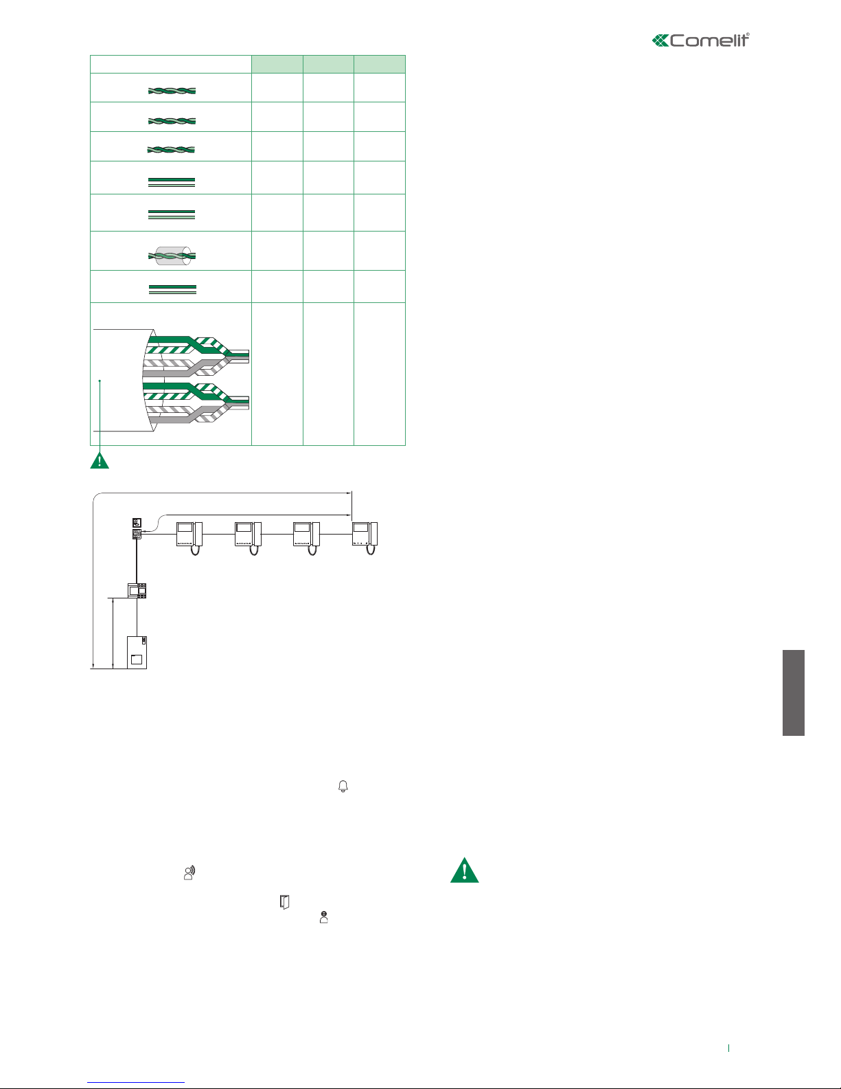
15
PT
No posto externo, premir o botão correspondente ao utilizador que
se pretende contactar para realizar a chamada.
√ O acendimento automático só é possível com a instalação em
espera.
Premir a tecla acendimento automático (tecla 2 por predefinição)
para visualizar no ecrã do monitor a imagem transmitida pelo posto
externo.
Premir a tecla programada para realizar a chamada:
Para terminar a chamada a decorrer e entrar em contacto com o
posto externo é necessário pousar o auscultador e voltar a levantálo (ou premir duas vezes a tecla de som).
Esta função permite enviar uma chamada a outros aparelhos
(vídeo-intercomunicadores e/ou telefones intercomunicadores)
configurados no mesmo endereço de chamada (para a programação,
consultar o manual técnico do respectivo posto interno).
Esta função permite chamar postos internos específicos (para a
programação, consultar o manual técnico do respectivo posto interno).
Uma chamada de um posto externo é prioritária relativamente a uma
comunicação de intercomunicação. Neste caso, os utilizadores que
estiverem em comunicação ouvirão um som semelhante ao som de
chamada, se a chamada lhes for dirigida, ou então três sons, e surgirá o
vídeo do posto externo emissor (no caso de monitores principais).
» Se o equipamento estiver livre:
o destinatário da chamada, levantando o auscultador (ou
premindo a tecla “activação do som”) entra em comunicação
com o emissor da chamada. Ao pousar o auscultador (ou
voltando a premir a tecla de som) termina a comunicação.
» Se o equipamento estiver ocupado:
o LED indicador pisca por alguns segundos (no caso do monitor
Mini o LED de privacidade pisca 4 vezes).
» Se o equipamento estiver livre: no posto externo acende-se o
LED para iluminar o emissor da chamada. O LED pisca e ouvese um som de confirmação. No(s) monitor(es) interno(s) principal(is)
surge automaticamente a imagem do posto externo. No caso de
monitores secundários, é possível visualizar o vídeo (sem responder
à chamada), premindo a tecla 2 (programada por predefinição para
o acendimento automático).
» Se o utilizador responder à chamada: no posto externo acende-
se o LED .
» Se o utilizador premir o comando de abertura da porta: no
posto externo acende-se o LED .
» Se a instalação estiver ocupada: o LED pisca e o posto
externo emite um som de instalação ocupada.
Realizar uma chamada de um posto externo
Acendimento automático
CHAMADA GERAL INTERNA
INTERCOMUNICAÇÃO SELECTIVA
Funcionamento com postos internos adicionais
Quando se efectua uma chamada do posto externo, o monitor que se
acende é o vídeo-intercomunicador principal. Os eventuais monitores
secundários da mesma unidade familiar permanecerão desligados.
Ao atender a chamada do posto externo de um vídeo-intercomunicador
secundário, a imagem será automaticamente visualizada no monitor (e
o monitor do vídeo-intercomunicador principal desliga-se).
Para visualizar a imagem sem activar o som no posto externo,
premir o botão 2 - acendimento automático/pedido de vídeo.
Funcionamento
O kit pode gerir um máximo de 4 vídeo-intercomunicadores ou
telefones intercomunicadores por cada botão de chamada, dos
quais no máximo 1 vídeo-intercomunicador principal.
MONITORES PRINCIPAIS/SECUNDÁRIOS
Funcionamento com postos internos adicionais
FUNCIONAMENTO COM COMUTADOR ART. 1404 (PREDEFINIÇÃO)
Para a programação das funções especiais, consultar o manual
técnico do posto externo art. 4893:
Na configuração do art. 1404, os DIP-SWITCHES “MIN” e “MAX”
definem, respectivamente, os códigos de utilizador mais baixos e
mais altos ligados à coluna. Para configurar os valores pretendidos,
consultar a tabela na pág 17. Comutadores relativos a colunas
diferentes devem gerir intervalos de códigos não sobrepostos. A
função acendimento automático só está disponível para instalações
como no esquema MNK/017CQC (para cada posto interno é possível
alternar entre o posto externo do kit e o posto externo principal).
• Posto externo (Porteiro) com comutador (secundário): função
predefinida a utilizar também em instalações com comutador art.
1404 (para a instalação de 3 ou mais entradas).
• Posto externo (Porteiro) secundário: função a utilizar em
instalações com comutador art. 1405 e 2 postos externos.
• Posto externo (Porteiro) principal: função a utilizar em instalações
com comutador art. 1405 e 2 postos externos.
FUNCIONAMENTO COM COMUTADOR ART. 1405
Com o comutador art. 1405 só é possível instalar 1 posto externo
principal e 1 posto externo secundário.
No modo “Posto externo principal” os comandos abertura da porta
(actuador) só são realizados se o posto externo estiver no estado de
chamada ou de acendimento automático. A função “door-open” está
sempre desactivada.
No modo “Posto externo secundário” os comandos abertura da
porta (actuador) são realizados se a instalação estiver em espera ou se
o posto externo estiver activado.
Com a instalação em espera o primeiro comando de acendimento
automático activa a câmara do posto externo secundário. Posteriores
comandos alternam entre os dois postos externos activando
alternativamente o posto externo principal e secundário.
1209
4893
1214/2C
1216
B
C
A
6700W
6701W
A MAX B MAX C MAX
Comelit Art.4577 1 mm2 (Ø 1,2 mm AWG 17)
200 m
(655 feet)
100 m
(330 feet)
200 m
(655 feet)
UTP5 cat. 5 0,2 mm2 (Ø 0,5 mm AWG 24)
100 m
(330 feet)
60 m
(195 feet)
100 m
(330 feet)
0,28 mm2 (Ø 0,6 mm AWG 23)
100 m
(330 feet)
60 m
(195 feet)
100 m
(330 feet)
0,5 mm2 (Ø 0,8 mm AWG 20)
100 m
(330 feet)
60 m
(195 feet)
100 m
(330 feet)
1 mm2 (Ø 1,2 mm AWG 17)
100 m
(330 feet)
60 m
(195 feet)
100 m
(330 feet)
1 mm2 (Ø 1,2 mm AWG 17)
80 m
(260 feet)
40 m
(130 feet)
80 m
(260 feet)
1,5 mm2 (Ø 1,4 mm AWG 15)
100 m
(330 feet)
60 m
(195 feet)
100 m
(330 feet)
*UTP5 cat. 5 0,2 mm2 (Ø 0,5 mm AWG 24)
MULTI PAIR CABLE
GREEN
ORANGE
BLU
GREEN / WHITE
ORANGE / WHITE
BLU / WHITE
BROWN / WHITE
BROWN
120 m
(390 feet)
70 m
(330 feet)
120 m
(390 feet)
*Cabo UTP com ligação multi-par: RESPEITAR AS CORES INDICADAS NA IMAGEM!
Page 16
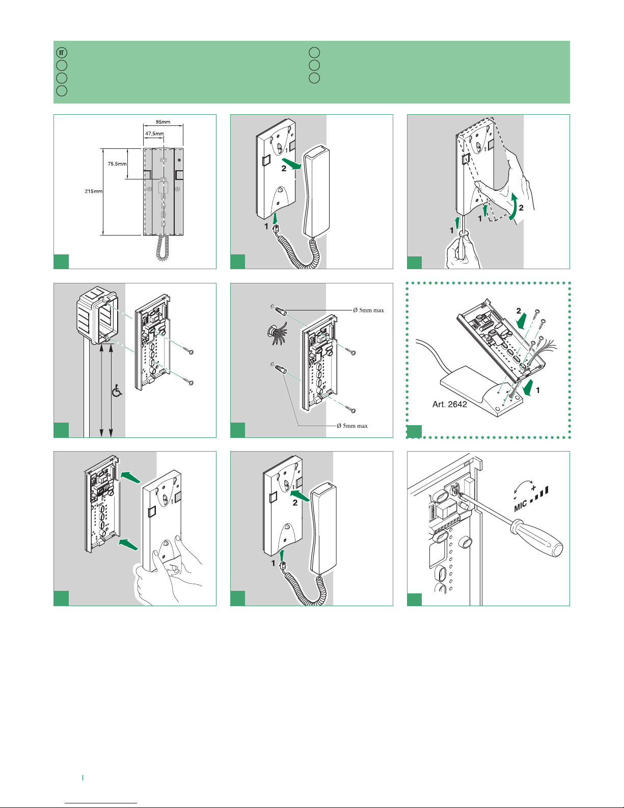
16
3
21
9
87
6
5
140-145 cm
115-125 cm
4
EN
FR
NL
DE
ES
PT
Installazione citofono Art. 2638
Installing door-entry phone Art. 2638
Installation combiné audio Art. 2638
Installatie deurtelefoon art. 2638
Installation der Innensprechstelle Art. 2638
Instalación del telefonillo art. 2638
Instalação do telefone intercomunicador art. 2638
Page 17
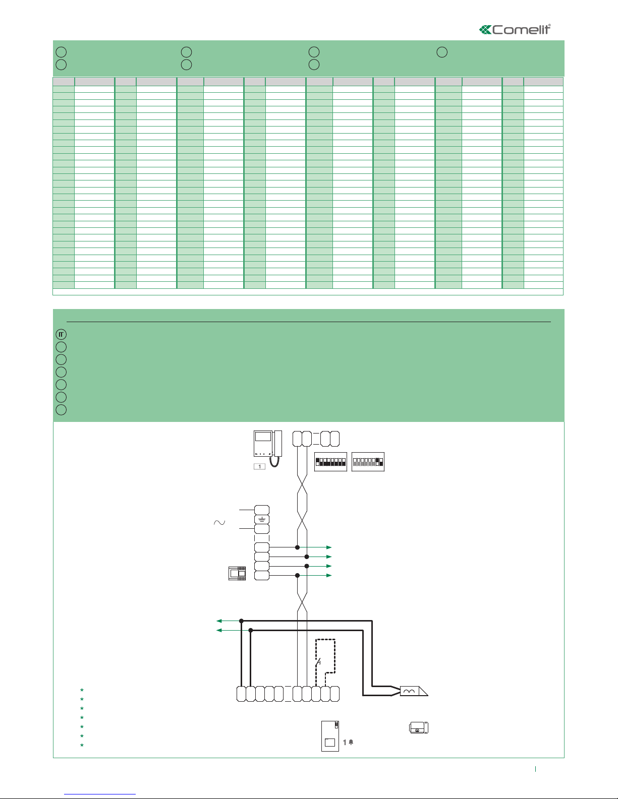
17
S1
ON
85 764321
1234 675 8
ON
S2
C
F
P
LL
C
F
P
1
2
6700W
6701W
6700W/BM
6701W/BM
LL
O
D
E
T
R
NO
SE
-
SE
+
NC C
M
O
C
1209
L
N
110-240V
L2
L2
L1
L1
4893
30 Vdc
30 Vdc
12 Vdc
0,25 A
*
EN
FR
NL
DE
ES
PT
MNK/039QC
Code Dip switch ON Code Dip switch ON Code Dip switch ON Code Dip switch ON Code Dip switch ON Code Dip switch ON Code Dip switch ON Code Dip switch ON
1 1 31 1,2,3,4,5 61 1,3,4,5,6 91 1,2,4,5,7 121 1,4,5,6,7 151 1,2,3,5,8 181 1,3,5,6,8 211 1,2,5,7,8
2 2 32 6 62 2,3,4,5,6 92 3,4,5,7 122 2,4,5,6,7 152 4,5,8 182 2,3,5,6,8 212 3,5,7,8
3 1,2 33 1,6 63 1,2,3,4,5,6 93 1,3,4,5,7 123 1,2,4,5,6,7 153 1,4,5,8 183 1,2,3,5,6,8 213 1,3,5,7,8
4 3 34 2,6 64 7 94 2,3,4,5,7 124 3,4,5,6,7 154 2,4,5,8 184 4,5,6,8 214 2,3,5,7,8
5 1,3 35 1,2,6 65 1,7 95 1,2,3,4,5,7 125 1,3,4,5,6,7 155 1,2,4,5,8 185 1,4,5,6,8 215 1,2,3,5,7,8
6 2,3 36 3,6 66 2,7 96 6,7 126 2,3,4,5,6,7 156 3,4,5,8 186 2,4,5,6,8 216 4,5,7,8
7 1,2,3 37 1,3,6 67 1,2,7 97 1,6,7 127 1,2,3,4,5,6,7 157 1,3,4,5,8 187 1,2,4,5,6,8 217 1,4,5,7,8
8 4 38 2,3,6 68 3,7 98 2,6,7 128 8 158 2,3,4,5,8 188 3,4,5,6,8 218 2,4,5,7,8
9 1,4 39 1,2,3,6 69 1,3,7 99 1,2,6,7 129 1,8 159 1,2,3,4,5,8 189 1,3,4,5,6,8 219 1,2,4,5,7,8
10 2,4 40 4,6 70 2,3,7 100 3,6,7 130 2,8 160 6,8 190 2,3,4,5,6,8 220 3,4,5,7,8
11 1,2,4 41 1,4,6 71 1,2,3,7 101 1,3,6,7 131 1,2,8 161 1,6,8 191 1,2,3,4,5,6,8 221 1,3,4,5,7,8
12 3,4 42 2,4,6 72 4,7 102 2,3,6,7 132 3,8 162 2,6,8 192 7,8 222 2,3,4,5,7,8
13 1,3,4 43 1,2,4,6 73 1,4,7 103 1,2,3,6,7 133 1,3,8 163 1,2,6,8 193 1,7,8 223 1,2,3,4,5,7,8
14 2,3,4 44 3,4,6 74 2,4,7 104 4,6,7 134 2,3,8 164 3,6,8 194 2,7,8 224 6,7,8
15 1,2,3,4 45 1,3,4,6 75 1,2,4,7 105 1,4,6,7 135 1,2,3,8 165 1,3,6,8 195 1,2,7,8 225 1,6,7,8
16 5 46 2,3,4,6 76 3,4,7 106 2,4,6,7 136 4,8 166 2,3,6,8 196 3,7,8 226 2,6,7,8
17 1,5 47 1,2,3,4,6 77 1,3,4,7 107 1,2,4,6,7 137 1,4,8 167 1,2,3,6,8 197 1,3,7,8 227 1,2,6,7,8
18 2,5 48 5,6 78 2,3,4,7 108 3,4,6,7 138 2,4,8 168 4,6,8 198 2,3,7,8 228 3,6,7,8
19 1,2,5 49 1,5,6 79 1,2,3,4,7 109 1,3,4,6,7 139 1,2,4,8 169 1,4,6,8 199 1,2,3,7,8 229 1,3,6,7,8
20 3,5 50 2,5,6 80 5,7 110 2,3,4,6,7 140 3,4,8 170 2,4,6,8 200 4,7,8 230 2,3,6,7,8
21 1,3,5 51 1,2,5,6 81 1,5,7 111 1,2,3,4,6,7 141 1,3,4,8 171 1,2,4,6,8 201 1,4,7,8 231 1,2,3,6,7,8
22 2,3,5 52 3,5,6 82 2,5,7 112 5,67 142 2,3,4,8 172 3,4,6,8 202 2,4,7,8 232 4,6,7,8
23 1,2,3,5 53 1,3,5,6 83 1,2,5,7 113 1,5,6,7 143 1,2,3,4,8 173 1,3,4,6,8 203 1,2,4,7,8 233 1,4,6,7,8
24 4,5 54 2,3,5,6 84 3,5,7 114 2,5,6,7 144 5,8 174 2,3,4,6,8 204 3,4,7,8 234 2,4,6,7,8
25 1,4,5 55 1,2,3,5,6 85 1,3,5,7 115 1,2,5,6,7 145 1,5,8 175 1,2,3,4,6,8 205 1,3,4,7,8 235 1,2,4,6,7,8
26 2,4,5 56 4,5,6 86 2,3,5,7 116 3,5,6,7 146 2,5,8 176 5,6,8 206 2,3,4,7,8 236 3,4,6,7,8
27 1,2,4,5 57 1,4,5,6 87 1,2,3,5,7 117 1,3,5,6,7 147 1,2,5,8 177 1,5,6,8 207 1,2,3,4,7,8 237 1,3,4,6,7,8
28 3,4,5 58 2,4,5,6 88 4,5,7 118 2,3,5,6,7 148 3,5,8 178 2,5,6,8 208 5,7,8 238 2,3,4,6,7,8
29 1,3,4,5 59 1,2,4,5,6 89 1,4,5,7 119 1,2,3,5,6,7 149 1,3,5,8 179 1,2,5,6,8 209 1,5,7,8 239 1,2,3,4,6,7,8
30 2,3,4,5 60 3,4,5,6 90 2,4,5,7 120 4,5,6,7 150 2,3,5,8 180 3,5,6,8 210 2,5,7,8 240 5,6,7,8
IT
EN
FR
NL
DE
ES
PT
Schema di collegamento base kit monofamiliare 8461M (/BM), 8461MB (/BM). Messa in funzione/verifica tensioni di impianto a riposo.
Pulsante comando apriporta locale
Indirizzi di montante
Connection diagram for standard single-family kit 8461M (/BM), 8461MB (/BM). Switching on/voltage check with system in standby.
Local lock release button
Riser addresses
Schéma de connexion de base kit un appel 8461M (/BM), 8461MB (/BM). Mise en service/vérification tensions d'installation au repos.
Bouton ouvre-porte sortie
Adresses de montant
Aansluitschema enkelvoudige basiskit 8461M (/BM), 8461MB (/BM). Inwerkingstelling/spanningscontrole van een systeem in de ruststand.
Lokale bedieningsknop deuropener
Adressen stamleiding
Grundanschlussplan Kit Einteilnehmerinstallation 8461M (/BM), 8461MB (/BM). Inbetriebnahme/Spannungsprüfung an der Anlage in Standby.
Taste lokaler Türöner
Adressen der Steigleitung
Esquema de conexión básico del kit unifamiliar arts. 8461M (/BM) y 8461MB (/BM). Puesta en funcionamiento/comprobación de las tensiones con la instalación en reposo.
Pulsador abrepuertas local
Direcciones de la columna montante
Esquema de ligação base do kit monofamiliar 8461M (/BM) e 8461MB (/BM). Colocação em funcionamento/controlo das tensões da instalação em espera
Botão de comando de abertura da porta local
Endereços da coluna
Page 18
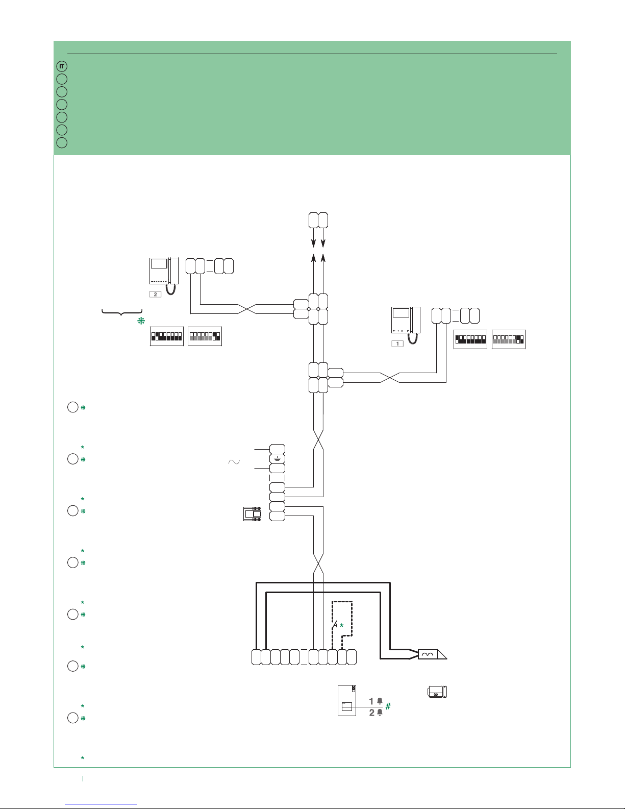
18
S1
ON
85 764321
1234 6 75 8
ON
S2
C
F
P
LL
C
F
P
1
2
LL
O
D
E
T
R
NO
SE
-
SE
+
NC C
M
O
C
1209
L
N
110-240V
L2
L2
L1
L1
4893
LM
LM
OUT
L
INLIN
L
OUT
L
1214/2C
LM
LM
OUT
L
INLIN
L
OUT
L
1214/2C
C
F
P
LL
C
F
P
1
2
S1
ON
85 764321
1234 6 75 8
ON
S2
LL
1216
6700W
6701W
6700W/BM
6701W/BM
6700W
6701W
6701B
6700W/BM
6701W/BM
6701B/BM
+ 6710
EN
FR
NL
DE
ES
PT
MNK/040QC
IT
NL
ES
PT
EN
FR
DE
Schema di collegamento espansione kit Art. 8461M (/BM), 8461MB (/BM) per impianto bifamiliare
I monitor supplementari Art. 6700W/BM, 6701W/
BM, 6701B/BM non includono la staa.
# Per programmare la funzione speciale “pulsanti
1-2 attivi con indirizzi di chiamata 1-2” consultare il
manuale tecnico dell’Art. 4893.
Pulsante comando apriporta locale.
Connection diagram for expansion kit 8461M (/BM), 8461MB (/BM) for two-family system
Additional monitors Art. 6700W/BM, 6701W/BM,
6701B/BM do not include a backplate.
# To program the special function “buttons 1-2
enabled with call addresses 1-2” refer to the technical
manual for Art. 4893.
Local lock release button.
Schéma de connexion extension kit Art. 8461M (/BM), 8461MB (/BM) pour installation deux appels
Les moniteurs supplémentaires Art. 6700W/BM,
6701W/BM, 6701B/BM ne sont pas équipés de l’étrier.
# Pour programmer la fonction spéciale « boutons 1-2
actifs avec adresses d’appel 1-2 », consulter le manuel
technique de l’Art. 4893.
Bouton ouvre-porte sortie.
Aansluitschema uitbreidingskit Art. 8461M (/BM), 8461MB (/BM) voor tweevoudige installatie
De extra monitoren Art. 6700W/BM, 6701W/BM, 6701B/BM
zijn exclusief muurplaat.
# Raadpleeg voor het programmeren van de speciale functie
“drukknoppen 1-2 actief met oproepadressen 1-2” de
technische handleiding van Art. 4893.
Lokale bedieningsknop deuropener.
Anschlussplan Erweiterung Kit Art. 8461M (/BM), 8461MB (/BM) für Zweiteilnehmerinstallation.
Die Zusatzmonitore Art. 6700W/BM, 6701W/BM, 6701B/BM
schließen nicht die Grundplatte ein.
# Für die Programmierung der Sonderfunktion “Tasten 1-2 aktiviert mit
mit Rufadressen 1-2” siehe technisches Handbuch des Art. 4893.
Taste lokaler Türöner.
Esquema de conexión de expansión del kit arts. 8461M (/BM) y 8461MB (/BM) para instalación bifamiliar
Los monitores adicionales arts. 6700W/BM, 6701W/
BM y 6701B/BM no incluyen la placa soporte.
# Para programar la función especial “pulsadores 1-2
activados con direcciones de llamada 1-2”, consultar el
manual técnico del art. 4893.
Pulsador abrepuertas local.
Esquema de ligação de expansão do kit art. 8461M (/BM) e 8461MB (/BM) para instalação bifamiliar
Os monitores adicionais art. 6700W/BM, 6701W/
BM e 6701B/BM não incluem o suporte.
# Para programar a função especial “botões 1-2
activos com endereços de chamada 1-2” consultar
o manual técnico do art. 4893.
Botão de comando de abertura da porta local.
Page 19
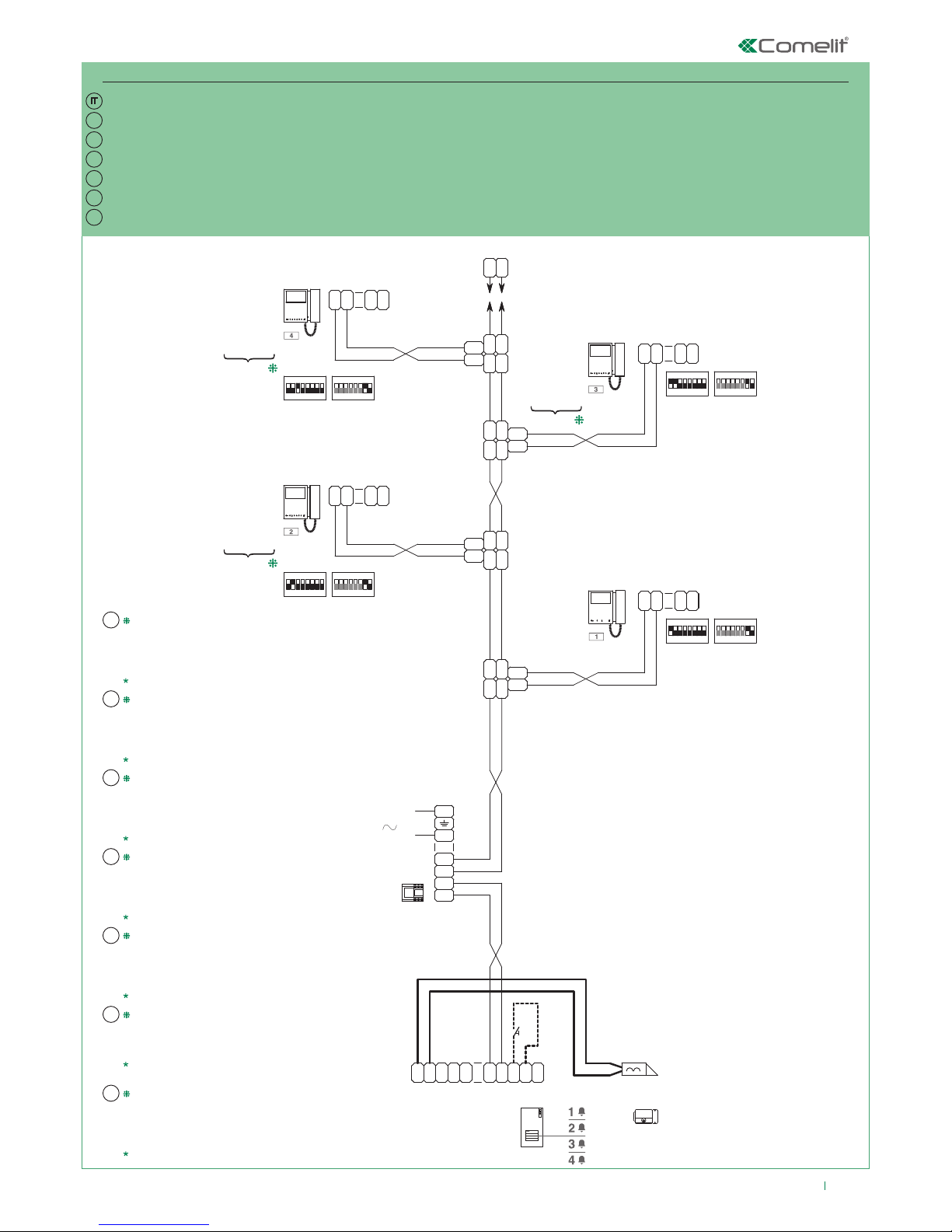
19
S1
ON
85 764321
1234 675 8
ON
S2
C
F
P
LL
C
F
P
1
2
LL
O
D
E
T
R
NO
SE
-
SE
+
NC C
M
O
C
1209
L
N
110-240V
L2
L2
L1
L1
4893
LM
LM
OUT
L
INLIN
L
OUT
L
1214/2C
LM
LM
OUT
L
INLIN
L
OUT
L
1214/2C
C
F
P
LL
C
F
P
1
2
LL
1216
S1
ON
85 764321
1234 675 8
ON
S2
C
F
P
LL
C
F
P
1
2
LM
LM
OUT
L
INLIN
L
OUT
L
1214/2C
LM
LM
OUT
L
INLIN
L
OUT
L
1214/2C
C
F
P
LL
C
F
P
1
2
S1
ON
85 764321
1234 675 8
ON
S2
6700W
6701W
6700W/BM
6701W/BM
S1
ON
85 764321 1234 675 8
ON
S2
6700W
6701W
6701B
6700W/BM
6701W/BM
6701B/BM
+ 6710
6700W
6701W
6701B
6700W/BM
6701W/BM
6701B/BM
+ 6710
6700W
6701W
6701B
6700W/BM
6701W/BM
6701B/BM
+ 6710
#
*
IT
EN
FR
NL
DE
ES
PT
MNK/041QC
NL
ES
PT
EN
FR
DE
Schema di collegamento espansione kit Art. 8461M (/BM), 8461MB (/BM) per impianto a 4 utenti
I monitor supplementari Art. 6700W/BM, 6701W/
BM, 6701B/BM non includono la staa.
# Per programmare la funzione speciale “pulsanti
1-2-3-4 attivi con indirizzi di chiamata 1-2-3-4”
consultare il manuale tecnico dell’Art. 4893.
Pulsante comando apriporta locale.
Connection diagram for expansion kit 8461M (/BM), 8461MB (/BM) for a 4-user system
Additional monitors Art. 6700W/BM, 6701W/BM, 6701B/
BM do not include a backplate.
# To program the special function “buttons 1-2-3-4 enabled
with call addresses 1-2-3-4” refer to the technical manual for
Art. 4893.
Local lock release button.
Schéma de connexion extension kit Art. 8461M (/BM), 8461MB (/BM) pour installation 4 appels
Les moniteurs supplémentaires Art. 6700W/BM,
6701W/BM, 6701B/BM ne sont pas équipés de l’étrier.
# Pour programmer la fonction spéciale « boutons 1-2-
3-4 actifs avec adresses d’appel 1-2-3-4 », consulter le
manuel technique de l’Art. 4893.
Bouton ouvre-porte sortie.
Aansluitschema uitbreidingskit Art. 8461M (/BM), 8461MB (/BM) voor systeem met 4 gebruikers
De extra monitoren Art. 6700W/BM, 6701W/BM, 6701B/BM
zijn exclusief muurplaat.
# Raadpleeg voor het programmeren van de speciale functie
“drukknoppen 1-2-3-4 actief met oproepadressen 1-2-3-4” de
technische handleiding van Art. 4893.
Lokale bedieningsknop deuropener.
Anschlussplan Erweiterung Kit Art. 8461M (/BM), 8461MB (/BM) für Vierteilnehmerinstallation.
Die Zusatzmonitore Art. 6700W/BM, 6701W/BM,
6701B/BM schließen nicht die Grundplatte ein.
# Für die Programmierung der Sonderfunktion “Tasten 1-2-
3-4 aktiviert mit Rufadressen 1-2-3-4” siehe technisches
Handbuch des Art. 4893.
Taste lokaler Türöner.
Esquema de conexión de expansión del kit arts. 8461M (/BM) y 8461MB (/BM) para instalación de 4 usuarios
Los monitores adicionales arts. 6700W/BM, 6701W/BM y 6701B/BM no
incluyen la placa soporte.
# Para programar la función especial “pulsadores 1-2-3-4 activados con
direcciones de llamada 1-2-3-4”, consultar el manual técnico del art. 4893.
Pulsador abrepuertas local.
Esquema de ligação de expansão do kit art. 8461M (/BM) e 8461MB (/BM) para instalação de 4 utilizadores
Os monitores adicionais art. 6700W/BM, 6701W/
BM e 6701B/BM não incluem o suporte.
# Para programar a função especial “botões 1-2-
3-4 activos com endereços de chamada 1-2-3-4”
consultar o manual técnico do art. 4893.
Botão de comando de abertura da porta local.
Page 20
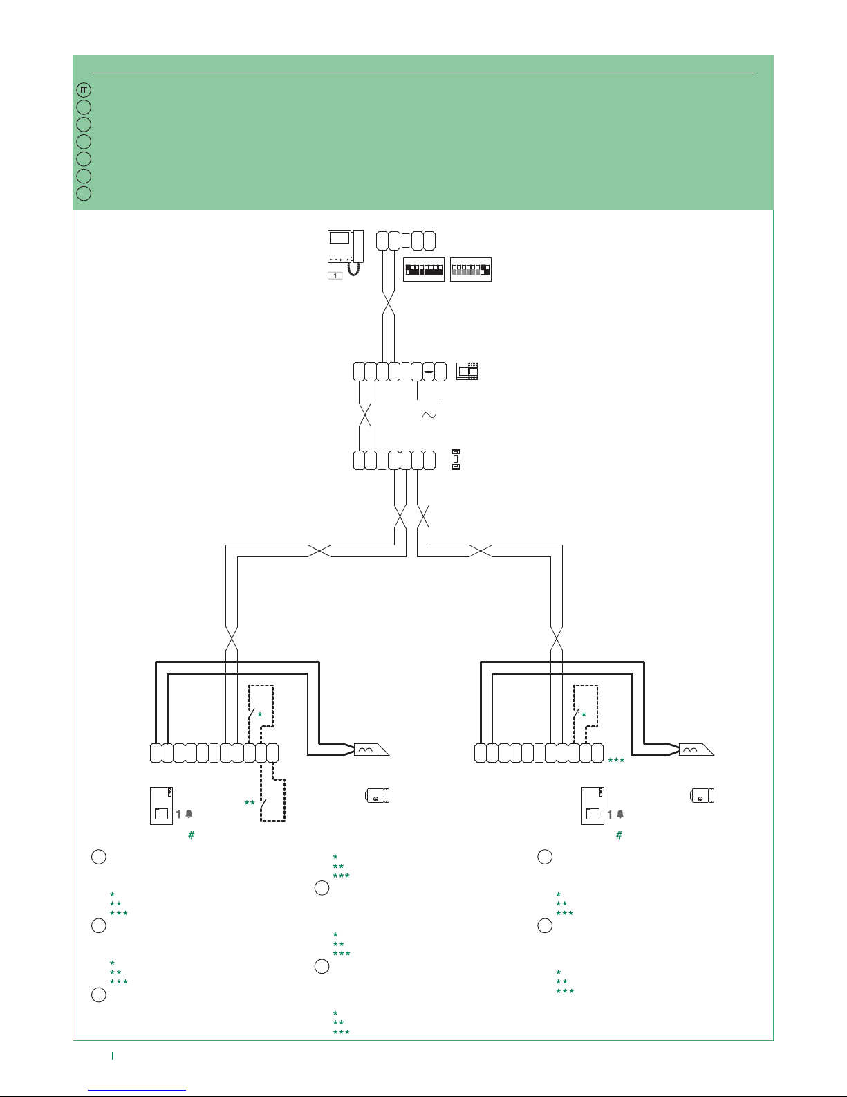
20
EN
FR
NL
DE
ES
PT
MNK/017AQC
IT
LL
O
D
E
T
R
NO
SE
-
SE
+
NC C
M
O
C
1209
4893
LL
O
D
E
T
R
NO
SE
-
SE
+
NC C
M
O
C
4893
1405
LMLMLSL
S
S1
ON
85 764321
1234 675 8
ON
S2
C
F
P
LL
C
F
P
1
2
LPL
P
L1 L1 L2 L2
L
N
110-240V
MAINSLAVE
6700W
6701W
6700W/BM
6701W/BM
EN
FR
NL
DE
ES
PT
Schema di collegamento impianto con posto esterno principale Art. 4893, posto esterno secondario Art. 4893 e scambio Art. 1405
# Per programmare le funzioni speciali “Posto esterno
(Porter) Principale” e “Posto esterno (Porter) Secondario”
consultare il manuale tecnico dell’Art. 4893. Per maggiori
informazioni sulle modalità di funzionamento vedi pag 3.
Pulsante comando apriporta locale.
Contatto N.C. per segnalazione porta aperta.
Segnalazione porta aperta non disponibile.
Connection diagram for system with main external unit Art. 4893, secondary external unit Art. 4893 and switching device Art. 1405
# To program the special functions “Main external unit
(Porter)” and “Secondary external unit (Porter)” refer to
the technical manual for Art. 4893. For further information
on operating modes see page5.
Local lock release button.
N.C. contact for door open indication.
Door open indication not available.
Schéma de connexion installation avec poste extérieur principal Art. 4893, poste extérieur secondaire Art. 4893 et commutateur Art. 1405
Bouton ouvre-porte sortie.
Contact N.F. pour signalisation porte ouverte.
Signalisation porte ouverte non disponible.
# Pour programmer les fonctions spéciales « Poste extérieur (HP)
principal » et « Poste extérieur (HP) secondaire », consulter le
manuel technique de l’Art. 4893. Pour de plus amples informations
sur les modalités de fonctionnement, voir page 7.
Aansluitschema installatie met hoofddeurstation Art. 4893, secundair deurstation Art. 4893 en deurselector Art. 1405
# Raadpleeg voor het programmeren van de speciale functies
“Hoofddeurstation (Hoofdspeakerunit)” en “Secundair
deurstation (Secundaire speakerunit)” de technische
handleiding van Art. 4893. Zie voor meer informatie over de
werkingsmodus pag 9.
Lokale bedieningsknop deuropener.
NC contact voor Signalering deur open.
Signalering deur open niet beschikbaar.
Anschlussplan der Anlage mit Haupt-Außensprechstelle Art. 4893, zusätzlicher Außensprechstelle Art. 4893 und Signalweiche Art. 1405
# Für die Programmierung der Sonderfunktionen “Haupt-
Außensprechstelle (Hauptzentrale)” und “Zusatz-
Außensprechstelle (Nebenzentrale)” siehe das technische
Handbuch des Art. 4893. Weitere Informationen über die
Funktionsweise finden Sie aus Seite 11.
Taste lokaler Türöner.
Önungskontakt für Anzeige oene Tür.
Anzeige Tür geönet nicht verfügbar.
Esquema de conexión de la instalación con placa externa principal art. 4893, placa externa secundaria art. 4893 y conmutador art. 1405
# Para programar las funciones especiales “Placa externa (unidad
externa) principal” y “Placa externa (unidad externa) secundaria”,
consultar el manual técnico del art. 4893. Para más información sobre
las modalidades de funcionamiento, véase la pág. 13.
Pulsador abrepuertas local.
Contacto N.C. para señalización de puerta abierta .
Señalización de puerta abierta no disponible.
Esquema de ligação de instalação com posto externo principal art. 4893, posto externo secundário art. 4893 e comutador art. 1405
# Para programar as funções especiais “Posto externo
(Porteiro) principal” e “Posto externo (Porteiro)
secundário”, consultar o manual técnico do art. 4893.
Para mais informações sobre o modo de funcionamento,
consultar a página 15.
Botão de comando de abertura da porta local.
Contacto N.C. para a indicação de porta aberta.
Indicação de porta aberta não disponível.
Page 21
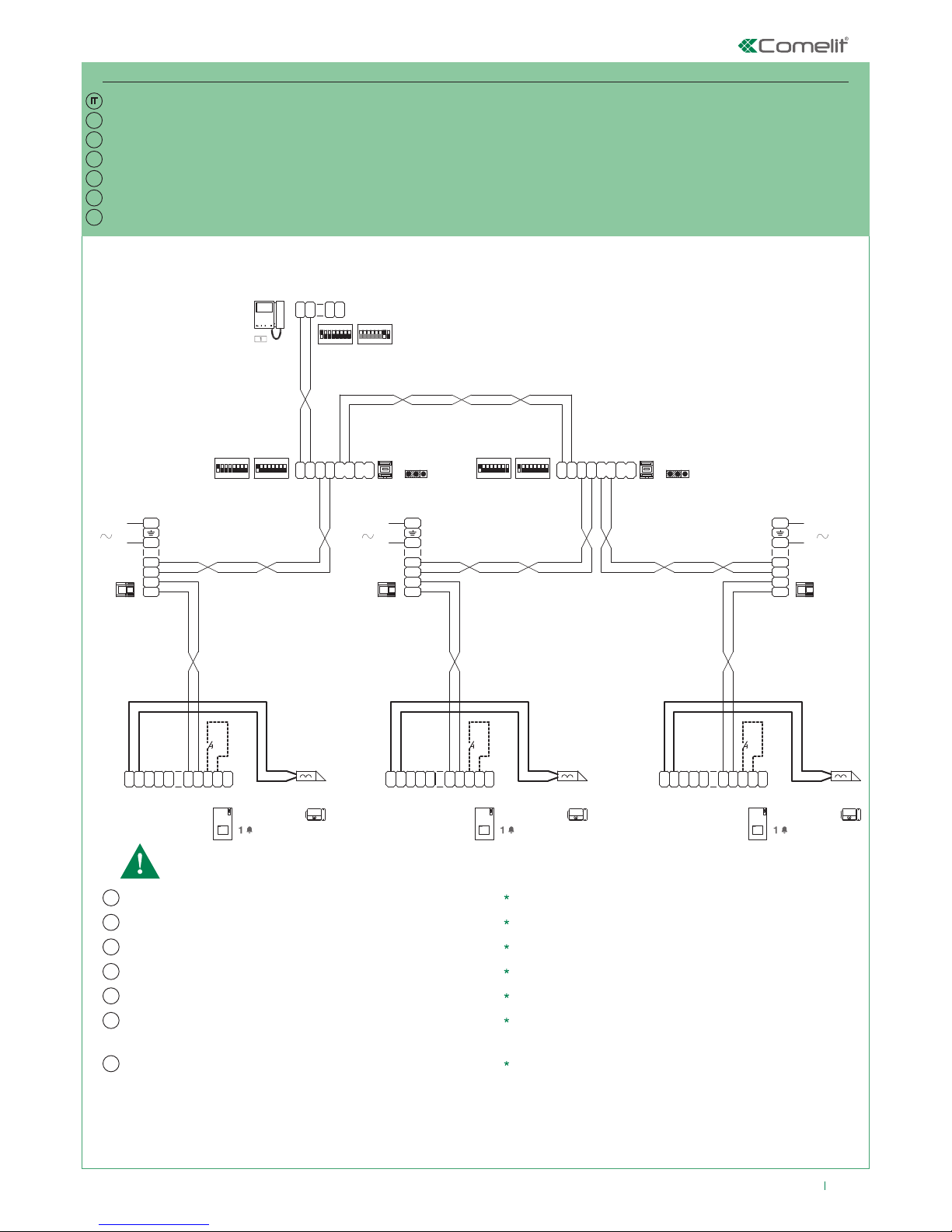
21
LL
O
D
E
T
R
NO
SE
-
SE
+
NC C
M
O
C
1209
L
N
110-240V
L2
L2
L1
L1
4893
1404
LMLMLSLSLP
IN
MAX
ON
85 764321
MIN
ON
85 764321
LP
OUT
A
B
JP1
S1
ON
85 764321
1234 675 8
ON
S2
C
F
P
LL
C
F
P
1
2
1404
LMLMLSLSLP
IN
MAX
ON
85 764321
MIN
ON
85 764321
LP
OUT
A
B
JP1
LL
O
D
E
T
R
NO
SE
-
SE
+
NC C
M
O
C
4893
L
N
110-240V
L2
L2
L1
L1
1209
LL
O
D
E
T
R
NO
SE
-
SE
+
NC C
M
O
C
1209
L
N
110-240V
L2
L2
L1
L1
4893
6700W
6701W
6700W/BM
6701W/BM
* * *
EN
FR
NL
DE
ES
PT
MNK/017QC
IT
EN
FR
NL
DE
ES
PT
Schema di collegamento impianto monofamiliare con 3 posti esterni Art. 4893 e scambio Art. 1404
Pulsante comando apriporta locale
La funzione “Posto esterno (Porter) con scambio (secondario)” è attiva di default (vedi pag. 3).
Le funzioni autoaccensione e segnalazione porta aperta non sono disponibili.
Connection diagram for single-family system with 3 external units Art. 4893 and switching device Art. 1404
Local lock release button
The function “External unit (Porter) with switching (secondary)” is active by default (see page 5).
The self-ignition and door open indication functions are not available.
Schéma de connexion installation un appel avec 3 postes extérieurs Art. 4893 et commutateur Art. 1404
Bouton ouvre-porte sortie
La fonction « Poste extérieur (HP) avec commutateur (secondaire) » est activée par défaut (voir page 7).
Les fonctions auto-allumage et signalisation porte ouverte ne sont pasdisponibles.
Aansluitschema enkelvoudige installatie met 3 deurstations Art. 4893 en deurselector Art. 1404
Lokale bedieningsknop deuropener
De functie “Deurstation (Speakerunit) met deurselector (secundair)” is standaard actief (zie pag.
9).
De functies Beeldoproep en Signalering deur open zijn niet beschikbaar.
Anschlussplan der Einteilnehmerinstallation mit 3 Außensprechstellen Art. 4893 und Signalweiche Art. 1404
Taste lokaler Türöner
Die Funktion “Außensprechstelle (Zentrale) mit Signalweiche (sekundär)” ist serienmäßig aktiviert (siehe Seite 11).
Die Funktionen Selbsteinschaltung und Anzeige Tür oen sind nicht verfügbar.
Esquema de conexión de la instalación unifamiliar con 3 placas externas art. 4893 y conmutador art. 1404
Pulsador abrepuertas local
La función “Placa externa (unidad externa) con conmutador (secundario)” se encuentra activada por
defecto (véase la pág. 13).
Las funciones de autoencendido y señalización de puerta abierta no se encuentran disponibles.
Esquema de ligação de instalação monofamiliar com 3 postos externos art. 4893 e comutador art. 1404
Botão de comando de abertura da porta local
A função “Posto externo (Porteiro) com comutador (secundário)” está activa por predefinição
(consultar a página 15).
A função acendimento automático e indicação de porta aberta não estão disponíveis.
Page 22
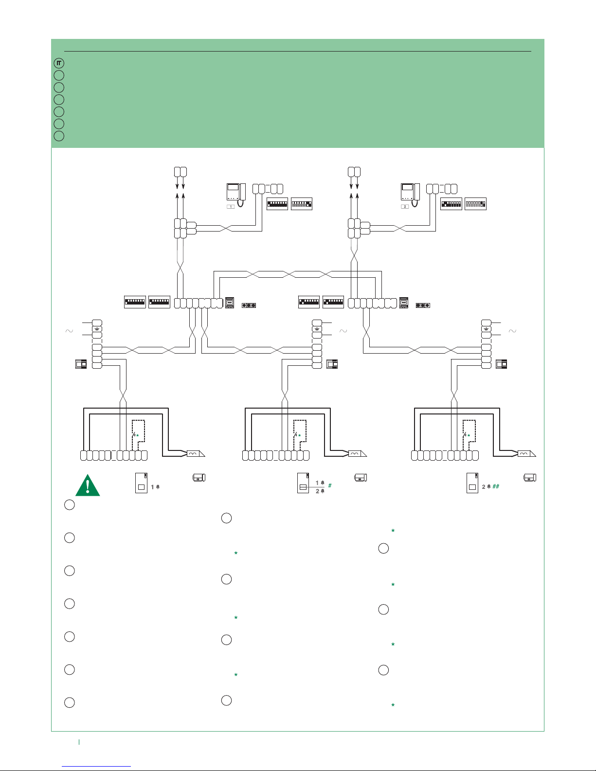
22
LL
O
D
E
T
R
NO
SE
-
SE
+
NC C
M
O
C
1209
L
N
110-240V
L2
L2
L1
L1
4893
1404
LMLMLSLSLP
IN
MAX
ON
85 764321
MIN
ON
85 764321
LP
OUT
A
B
JP1
LL
O
D
E
T
R
NO
SE
-
SE
+
NC C
M
O
C
4893
L
N
110-240V
L2
L2
L1
L1
1209
LL
O
D
E
T
R
NO
SE
-
SE
+
NC C
M
O
C
4893
S1
ON
85 764321
1234 675 8
ON
S2
C
F
P
LL
C
F
P
1
2
LM
LM
OUT
L
INLIN
L
OUT
L
1214/2C
LL
1216
1404
LMLMLSLSLP
IN
MAX
ON
85 764321
MIN
ON
85 764321
LP
OUT
A
B
JP1
S1
ON
85 764321
1234 675 8
ON
S2
C
F
P
LL
C
F
P
1
2
LM
LM
OUT
L
INLIN
L
OUT
L
1214/2C
LL
1216
L
N
110-240V
L2
L2
L1
L1
1209
6700W
6701W
6700W/BM
6701W/BM
6700W
6701W
6700W/BM
6701W/BM
NL
NL
DE
DE
ES
ES
PT
PT
IT
IT
EN
FR
NL
DE
ES
PT
MNK/017CQC
EN
FR
EN
FR
La funzione “Posto esterno (Porter) con scambio
(secondario)” è attiva di default (vedi pag. 3). La
funzione segnalazione porta aperta non è disponibile. La
funzione autoaccensione è disponibile (con possibilità di
bascula su 2 posti esterni).
Schema di collegamento impianto con 2 kit monofamiliari e posto esterno principale Art. 4893
# Per programmare la funzione speciale “pulsanti 1-2
attivi con indirizzi di chiamata 1-2” consultare il manuale
tecnico dell’Art. 4893.
## Per programmare l’indirizzo di chiamata consultare il
manuale tecnico dell’Art. 4893.
Pulsante comando apriporta locale.
Connection diagram for system with 2 single-family kits and main external unit Art. 4893
The function “External unit (Porter) with switching
(secondary)” is active by default (see page 5). The
door open indication function is not available. The
self-ignition function is available (with toggle function
between 2 external units).
# To program the special function “buttons 1-2 enabled
with call addresses 1-2” refer to the technical manual
for Art. 4893.
## To program the call address refer to the technical
manual for Art. 4893.
Local lock release button.
Schéma de connexion installation avec 2 kits un appel et poste extérieur principal Art. 4893
La fonction « Poste extérieur (HP) avec commutateur
(secondaire) » est activée par défaut (voir page 7). La
fonction signalisation porte ouverte n’est pas disponible. La
fonction auto-allumage est disponible (avec possibilité de
basculer sur 2 postes extérieurs).
#Pour programmer la fonction spéciale « boutons 1-2 actifs
avec adresses d’appel 1-2 », consulter le manuel technique
de l’Art. 4893.
## Pour programmer l’adresse d’appel, consulter le manuel
technique de l’Art. 4893.
Bouton ouvre-porte sortie.
Aansluitschema systeem met 2 enkelvoudige installatiekits en hoofddeurstation Art. 4893
De functie “Deurstation (Porter) met deurselector
(secundair)” is standaard actief (zie pag. 9). De
functie Signalering deur open is niet beschikbaar. De
functie Beeldoproep is beschikbaar (met mogelijkheid
om te wisselen tussen de 2 deurstations).
# Raadpleeg voor het programmeren van de speciale
functie “drukknoppen 1-2 actief met oproepadressen
1-2” de technische handleiding van Art. 4893.
## Raadpleeg voor het programmeren van het
oproepadres de technische handleiding van Art. 4893.
Lokale bedieningsknop deuropener.
Anschlussplan der Anlage mit 2 Kit Einteilnehmerinstallation und Haupt-Außensprechstelle Art. 4893
Die Funktion “Außensprechstelle (Zentrale) mit Signalweiche
(sekundär)” ist serienmäßig aktiviert (siehe Seite 11). Die
Funktion Anzeige Tür oen ist nicht verfügbar. Die Funktion
Selbsteinschaltung ist verfügbar (mit Umschalter zwischen 2
Außensprechstellen).
# Für die Programmierung der Sonderfunktion “Tasten 1-2
aktiviert mit mit Rufadressen 1-2” siehe das technische
Handbuch des Art. 4893.
## Für die Programmierung der Rufadresse siehe das technische
Handbuch des Art. 4893.
Taste lokaler Türöner.
Esquema de conexión de la instalación con 2 kits unifamiliares y placa externa principal art. 4893
La función “Placa externa (unidad externa) con conmutador
(secundario)” se encuentra activada por defecto (véase la
pág. 13). La función de señalización de puerta abierta no se
encuentra disponible. La función autoencendido se encuentra
disponible (con posibilidad de bascular en 2 placas externas).
# Para programar la función especial “pulsadores 1-2
activados con direcciones de llamada 1-2”, consultar el
manual técnico del art. 4893.
## Para programar la dirección de la llamada, consultar el
manual técnico del art. 4893.
Pulsador abrepuertas local.
Esquema de ligação de instalação com 2 kits monofamiliares e posto externo principal art. 4893
A função “Posto externo (Porteiro) com comutador
(secundário)” está activa por predefinição (consultar a
página 15). A função indicação de porta aberta não está
disponível. A função acendimento automático está disponível
(com a possibilidade de alternar entre 2 postos externos).
# Para programar a função especial “botões 1-2 activos
com endereços de chamada 1-2” consultar o manual
técnico do art. 4893.
## Para programar o endereço de chamada consultar o
manual técnico do art. 4893.
Botão de comando de abertura da porta local.
Page 23
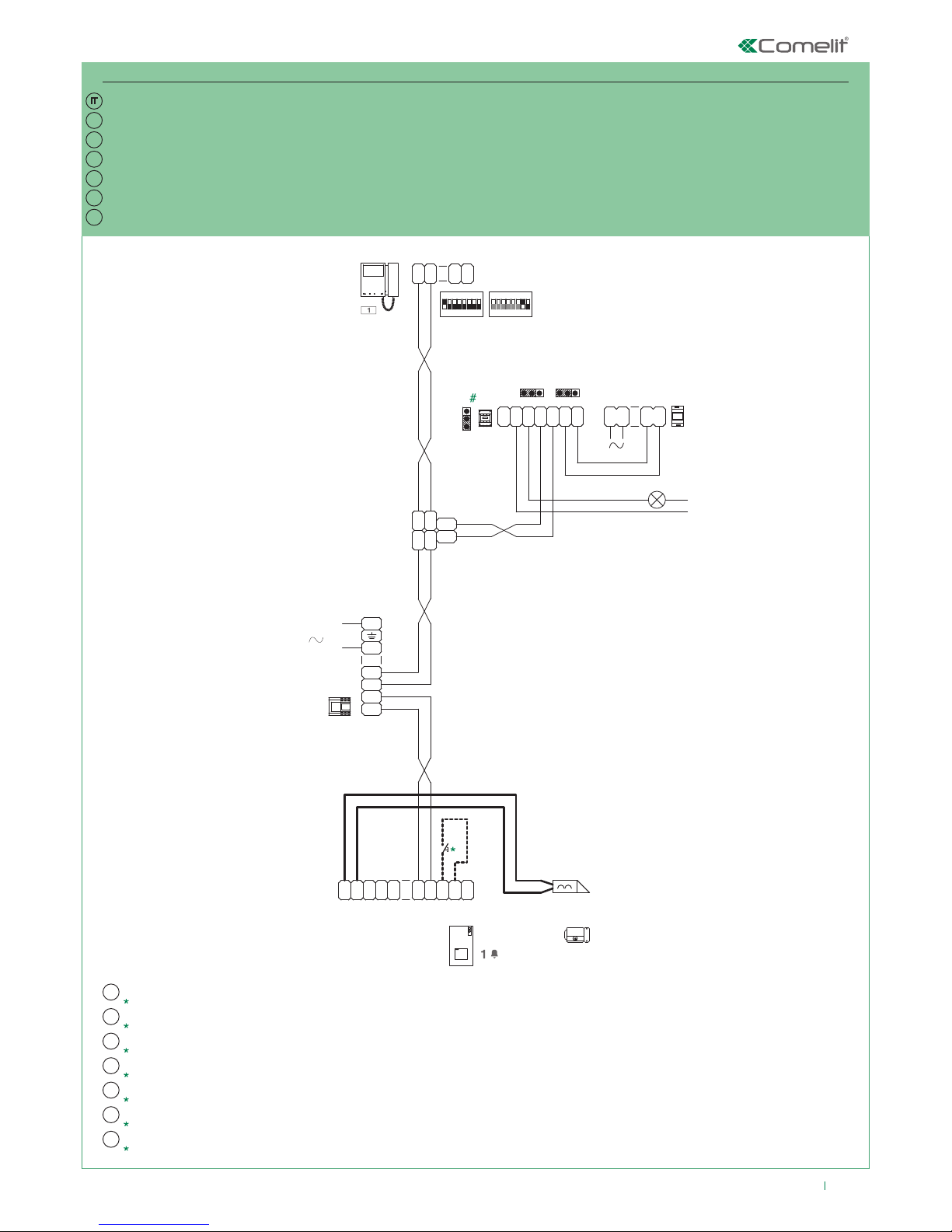
23
LL
O
D
E
T
R
NO
SE
-
SE
+
NC C
M
O
C
1209
L
N
110-240V
L2
L2
L1
L1
4893
C
N
O
CNL L
~-~
+
L
OUT
LINL
IN
L
OUT
LM
LM
1214/2C
1256
12/24V
AC/DC
12V~
1200
230V~
S1
ON
85 764321
1234 6 75 8
ON
S2
C
F
P
LL
C
F
P
1
2
JP2
2 1
12
JP3
JP4
2
1
6700W
6701W
6700W/BM
6701W/BM
EN
FR
NL
DE
ES
PT
MNK/EQC
IT
EN
FR
NL
DE
ES
PT
Schema di collegamento kit monofamiliare 8461M (/BM) e 8461MB (/BM), con aggiunta dell'Art. 1256
# Per maggiori informazioni si veda il relativo manuale.
Pulsante comando apriporta locale.
Connection diagram for single-family kit 8461M (/BM) and 8461MB (/BM), with addition of Art. 1256
# For further information see the respective manual.
Local lock release button.
Schéma de connexion kit un appel 8461M (/BM) et 8461MB (/BM), auquel est ajouté l'Art. 1256
# Pour de plus amples informations, consulter le manuel correspondant.
Bouton ouvre-porte sortie.
Aansluitschema enkelvoudige installatiekit 8461M (/BM) en 8461MB (/BM), met toevoeging van Art. 1256
# Raadpleeg voor meer informatie de betreende handleiding.
Lokale bedieningsknop deuropener.
Anschlussplan Kit Einteilnehmerinstallation 8461M (/BM) und 8461MB (/BM) mit zusätzlichem Art. 1256
# Für weitere Informationen siehe das betreenden Handbuch.
Taste lokaler Türöner.
Esquema de conexión del kit unifamiliar 8461M (/BM) y 8461MB (/BM) con el art. 1256
# Para más información, consultar el manual correspondiente.
Pulsador abrepuertas local.
Esquema de ligação de kit monofamiliar 8461M (/BM) e 8461MB (/BM), com a adição do art. 1256
# Para mais informações, consultar o respectivo manual técnico.
Botão de comando de abertura da porta local.
Page 24
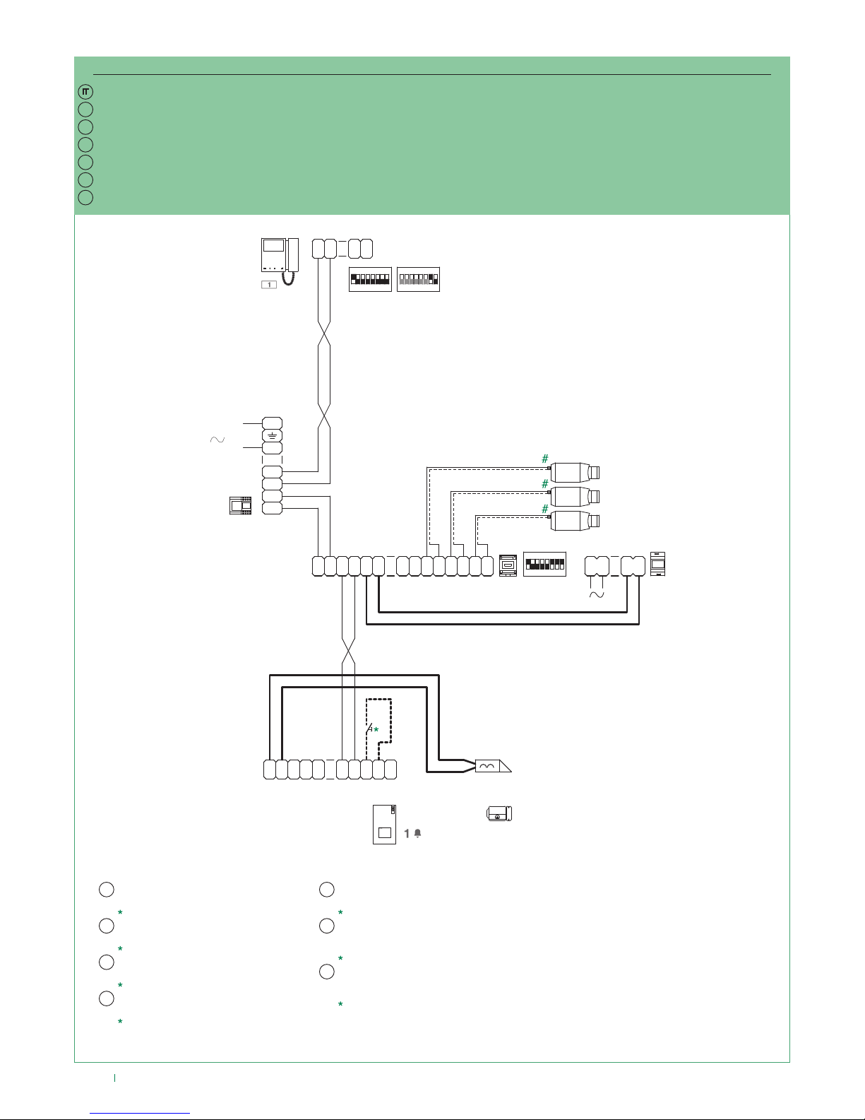
24
LL
O
D
E
T
R
NO
SE
-
SE
+
NC C
M
O
C
1209
L
N
110-240V
L2
L2
L1
L1
4893
1234 675 8
ON
1409
G
NDAN
I
3
V S
32SV2S11
V
+
-
~ ~
LLL
OUTLOUT
IN IN
230V~
12V~
1200
C
F
P
LL
C
F
P
1
2
S1
ON
85 764321
1234 675 8
ON
S2
6700W
6701W
6700W/BM
6701W/BM
EN
FR
NL
DE
ES
PT
MNK/015QC
IT
NL
DE
ES
EN
FR
PT
Schema di collegamento kit monofamiliare 8461M (/BM), 8461MB (/BM), con aggiunta di un modulo per telecamera scorporata Art. 1409
# Da alimentare separatamente. Per il settaggio e il
funzionamento dell’Art. 1409 vedi il relativo manuale.
Pulsante comando apriporta locale.
Connection diagram for single-family kit 8461M (/BM) and 8461MB (/BM), with addition of a remote camera module Art. 1409
# To be powered separately. For the setting and
operation of Art.1409 see the respective manual.
Local lock release button.
Schéma de connexion kit un appel 8461M (/BM), 8461MB (/BM), auquel est ajouté un module pour caméra déportée Art. 1409
# À alimenter séparément. Pour le paramétrage et le
fonctionnement de l’Art. 1409, consulter le manuel correspondant.
Bouton ouvre-porte sortie.
Aansluitschema enkelvoudige installatiekit 8461M (/BM), 8461MB (/BM), met toevoeging van externe cameramodule Art. 1409
# Apart te voeden. Raadpleeg voor de instelling en de
werking van Art.1409 de betreende handleiding.
Lokale bedieningsknop deuropener.
Anschlussplan Kit Einteilnehmerinstallation 8461M (/BM) und 8461MB (/BM) mit zusätzlichem Modul für separate Kamera Art. 1409
# Separate Stromversorgung erforderlich. Für die Einstellung und
den Betrieb des Art. 1409 siehe das betreenden Handbuch.
Taste lokaler Türöner.
Esquema de conexión del kit unifamiliar 8461M (/BM) y 8461MB (/BM) con un módulo para telecámara separada art. 1409
# Alimentar por separado. Para la configuración y
el funcionamiento del art. 1409, consultar el manual
correspondiente.
Pulsador abrepuertas local.
Esquema de ligação de kit monofamiliar 8461M (/BM) e 8461MB (/BM), com a adição de um módulo para câmara separada art. 1409
# Alimentar separadamente. Para informações sobre a
programação e o funcionamento do art. 1409, consultar
o respectivo manual.
Botão de comando de abertura da porta local.
Page 25
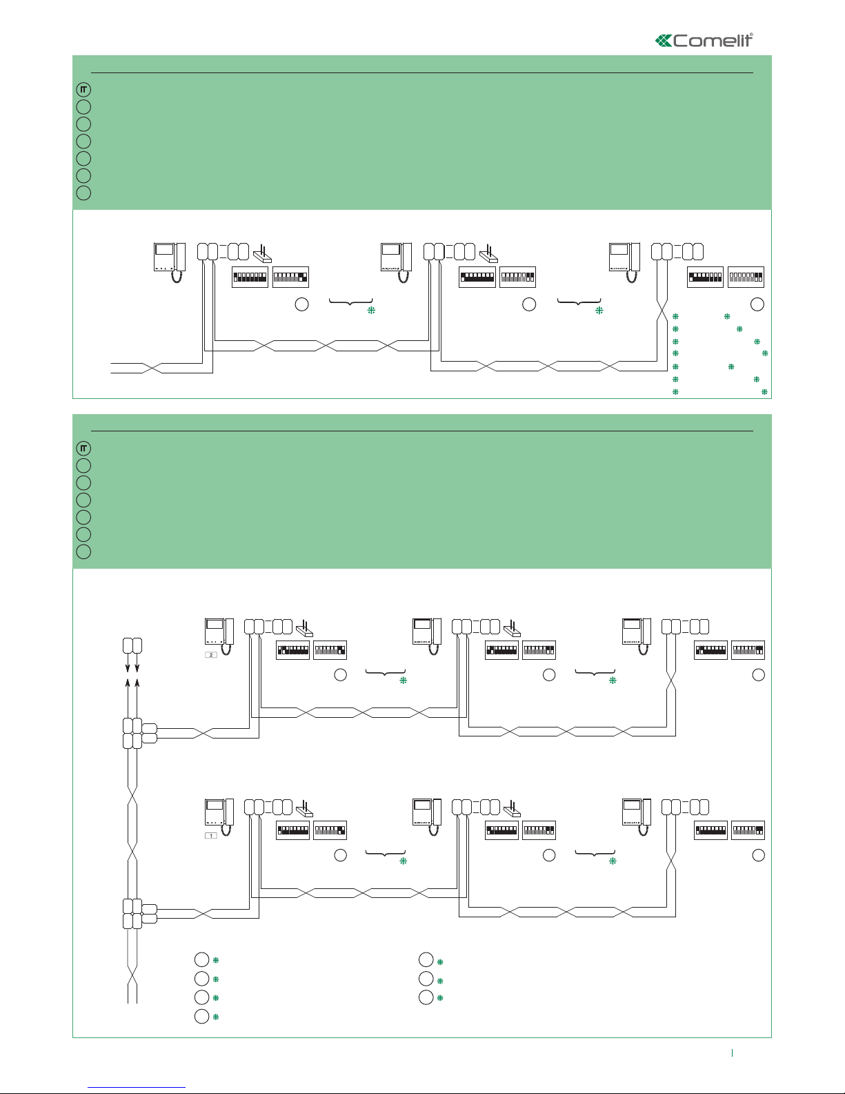
25
P
S S
1234 675 8
ON
S2
1234 675 8
ON
S2
CV5
S1
ON
85 764321
1234 675 8
ON
S1
C
F
P
LL
C
F
P
1
2
C
F
P
LL
C
F
P
1
2
1209
CV5
1234 675 8
ON
S2
1234 675 8
ON
S1
C
F
P
LL
C
F
P
1
2
6700W
6701W
6700W/BM
6701W/BM
6700W
6701W
6701B
6700W/BM
6701W/BM
6701B/BM
+ 6710
6700W
6701W
6701B
6700W/BM
6701W/BM
6701B/BM
+ 6710
1234 675 8
ON
S2
1234 675 8
ON
S2
CV5
S1
ON
85 764321 1234 675 8
ON
S1
C
F
P
LL
C
F
P
1
2
C
F
P
LL
C
F
P
1
2
CV5
1234 675 8
ON
S2
1234 675 8
ON
S1
C
F
P
LL
C
F
P
1
2
LL
1216
LM
LM
OUT
L
INLIN
L
OUT
L
1214/2C
LM
LM
OUT
L
INLIN
L
OUT
L
1214/2C
1209
1234 675 8
ON
S2
1234 675 8
ON
S2
CV5
S1
ON
85 764321 1234 675 8
ON
S1
C
F
P
LL
C
F
P
1
2
C
F
P
LL
C
F
P
1
2
CV5
1234 675 8
ON
S2
1234 675 8
ON
S1
C
F
P
LL
C
F
P
1
2
6700W
6701W
6700W/BM
6701W/BM
6700W
6701W
6701B
6700W/BM
6701W/BM
6701B/BM
+ 6710
6700W
6701W
6701B
6700W/BM
6701W/BM
6701B/BM
+ 6710
6700W
6701W
6700W/BM
6701W/BM
6700W
6701W
6701B
6700W/BM
6701W/BM
6701B/BM
+ 6710
6700W
6701W
6701B
6700W/BM
6701W/BM
6701B/BM
+ 6710
P S S
P S S
EN
EN
FR
FR
NL
NL
DE
DE
ES
ES
PT
PT
MNK/Q23
MNK/Q21
IT
EN
FR
NL
DE
ES
PT
Schema di collegamento impianto monofamiliare 8461M (/BM) e 8461MB (/BM), con un monitor principale e 2 monitor secondari (in cascata)
Schema di collegamento impianto bifamiliare, con un monitor principale e 2 monitor secondari (in cascata)
I monitor supplementari Art. 6700W/BM, 6701W/BM,
6701B/BM non includono la staa.
Vedi nota sotto
Connection diagram for single-family kit 8461M (/BM) and 8461MB (/BM), with one main monitor and 2 secondary monitors (cascade connection)
Connection diagram for two-family system with one main monitor and 2 secondary monitors (cascade connection)
Additional monitors Art. 6700W/BM, 6701W/BM,
6701B/BM do not include a backplate.
See note below
Schéma de connexion installation un appel 8461M (/BM) et 8461MB (/BM), avec un moniteur principal et 2 moniteurs secondaires (en cascade)
Schéma de connexion installation deux appels, avec un moniteur principal et 2 moniteurs secondaires (en cascade)
Les moniteurs supplémentaires Art. 6700W/BM, 6701W/
BM, 6701B/BM ne sont pas équipés de l’étrier.
Voir remarque ci-dessous
Aansluitschema enkelvoudige installatie 8461M (/BM) en 8461MB (/BM), met een hoofdmonitor en 2 secundaire monitoren (in cascade)
Aansluitschema tweevoudige installatie met een hoofdmonitor en 2 secundaire monitoren (in cascade)
De extra monitoren Art. 6700W/BM, 6701W/BM,
6701B/BM zijn exclusief muurplaat.
Zie onderstaande opmerking
Anschlussplan Kit Einteilnehmerinstallation 8461M (/BM) und 8461MB (/BM) mit einem Hauptmonitor und 2 Zusatzmonitoren (in Kaskadenschaltung).
Anschlussplan Zweiteilnehmerinstallation mit einem Hauptmonitor und 2 Zusatzmonitoren (in Kaskadenschaltung).
Die Zusatzmonitore Art. 6700W/BM, 6701W/BM, 6701B/BM schließen nicht die
Grundplatte ein.
Siehe Hinweis in
Esquema de conexión de la instalación unifamiliar 8461M (/BM) y 8461MB (/BM), con un monitor principal y 2 monitores secundarios (en cascada)
Esquema de conexión de la instalación bifamiliar con un monitor principal y 2 monitores secundarios (en cascada)
Los monitores adicionales arts. 6700W/BM, 6701W/BM y 6701B/BM
no incluyen la placa soporte.
Véase nota más abajo
Esquema de ligação de instalação monofamiliar 8461M (/BM) e 8461MB (/BM), com um monitor principal e 2 monitores secundários (em cascata)
Esquema de ligação de instalação bifamiliar, com um monitor principal e 2 monitores secundários (em cascata)
Os monitores adicionais art. 6700W/BM, 6701W/BM e
6701B/BM não incluem o suporte.
Consultar a nota abaixo
Page 26
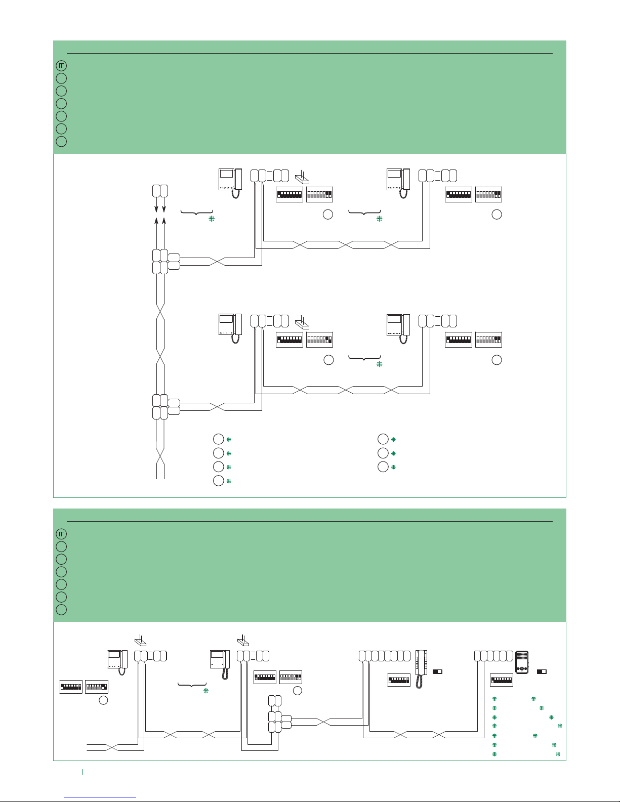
26
EN
FR
NL
DE
ES
PT
MNK/Q22
EN
FR
NL
DE
ES
PT
MNK/AAD
IT
EN
FR
NL
DE
ES
PT
LM
LM
1214/2C
OUT
L
INLIN
L
OUT
L
1216
L L
6228B
6228W
SW1
S2 S1
S+S
-
C
F
P
L L
C
F
P
S1
ON
85 764321
1234 675 8
ON
S2
C
F
P
LL
C
F
P
1
2
1214/2C
1209
33
P C S
-
L L
C
F
P
C
F
P
S
+
2610
SW3
S2 S1
CV5
S1
ON
85 764321
S1
ON
85 764321
S1
ON
85 764321
1234 675 8
ON
S2
C
F
P
LL
C
F
P
1
2
CV5
P
S
6700W
6701W
6701B
6700W/BM
6701W/BM
6701B/BM
+ 6710
12 34 56
6700W
6701W
6700W/BM
6701W/BM
LL
1216
1234 675 8
ON
S2
1234 675 8
ON
S2
CV5
S1
ON
85 764321
1234 675 8
ON
S1
LM
LM
OUT
L
INLIN
L
OUT
L
1214/2C
LM
LM
OUT
L
INLIN
L
OUT
L
1214/2C
C
F
P
LL
C
F
P
1
2
C
F
P
LL
C
F
P
1
2
1209
1234 675 8
ON
S2
1234 675 8
ON
S2
CV5
S1
ON
85 764321
1234 675 8
ON
S1
C
F
P
LL
C
F
P
1
2
C
F
P
LL
C
F
P
1
2
6700W
6701W
6700W/BM
6701W/BM
6700W
6701W
6701B
6700W/BM
6701W/BM
6701B/BM
+ 6710
6700W
6701W
6701B
6700W/BM
6701W/BM
6701B/BM
+ 6710
6700W
6701W
6701B
6700W/BM
6701W/BM
6701B/BM
+ 6710
P S
SS
Schema di collegamento impianto con espansione massima in derivazione per singolo indirizzo di chiamata
Schema di collegamento in cascata da posto interno video dei citofoni supplementari Art. 2610 e Art. 6228(B)(W)
I monitor supplementari Art. 6700W/BM, 6701W/BM,
6701B/BM non includono la staa.
Vedi nota sopra
Connection diagram for system with maximum expansion in branch connection for single call address
Connection diagram for cascade connection from internal video unit of additional door-entry phones Art. 2610 and Art. 6228(B)(W)
Additional monitors Art. 6700W/BM, 6701W/BM,
6701B/BM do not include a backplate.
See note above
Schéma de connexion installation avec extension maximale en dérivation pour chaque adresse d'appel
Schéma de connexion en cascade à partir d'un poste intérieur vidéo des combinés audio supplémentaires Art. 2610 et Art. 6228(B)(W)
Les moniteurs supplémentaires Art. 6700W/BM, 6701W/
BM, 6701B/BM ne sont pas équipés de l’étrier.
Voir remarque ci-dessus
Aansluitschema installatie met maximale uitbreiding en afgetakte aansluiting per afzonderlijk oproepadres
Aansluitschema met afgetakte aansluiting vanaf het binnentoestel met beeld van de extra deurtelefoons Art. 2610 en Art. 6228(B)(W)
De extra monitoren Art. 6700W/BM, 6701W/BM,
6701B/BM zijn exclusief muurplaat.
Zie bovenstaande opmerking
Anschlussplan Anlage mit maximaler Erweiterung über Abzweigung für eine einzelne Rufadresse
Anschlussplan in Kaskadenschaltung von der Video-Innensprechstelle der zusätzlichen Innensprechstellen Art. 2610 und Art. 6228 (B)(W)
Die Zusatzmonitore Art. 6700W/BM, 6701W/BM, 6701B/BM
schließen nicht die Grundplatte ein.
Siehe Hinweis in
Esquema de conexión de la instalación con expansión máxima en derivación para una única dirección de llamada
Esquema de conexión en cascada, desde la unidad interna vídeo, de los telefonillos adicionales art. 2610 y art. 6228(B)(W)
Los monitores adicionales arts. 6700W/BM, 6701W/BM y
6701B/BM no incluyen la placa soporte.
Véase nota más arriba
Esquema de ligação de instalação com expansão máxima em derivação para um único endereço de chamada
Esquema de ligação em cascata do posto interno vídeo de telefones intercomunicadores adicionais art. 2610 e art. 6228(B)(W)
Os monitores adicionais art. 6700W/BM, 6701W/BM e
6701B/BM não incluem o suporte.
Consultar a nota acima
Page 27
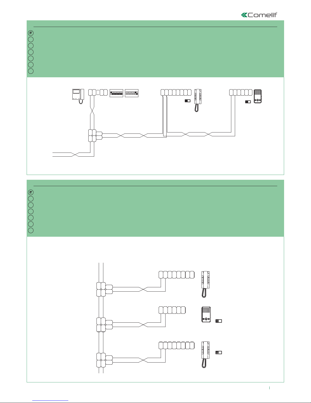
27
1214/2C
LM
LM
OUT
L
INLIN
L
OUT
L
L
OUT
LINL
IN
L
OUT
LM
LM
1214/2C
1214/2C
LM
LM
OUT
L
INLIN
L
OUT
L
2610
+
S
P
F
C
P
F
C
LL
-
SCP
2 2
P
F
C
LL
P
F
C
-
S+S
S1S2
SW1
6228W
6228B
1209
1214/2C
6700W
6701W
6701B
SW3
S2 S1
2628/
+
S
P
F
C
P
F
C
LL
-
SCP
3 3
2638
EN
EN
FR
FR
NL
NL
DE
DE
ES
ES
PT
PT
MNK/AAE
MNK/FC
1209
L
OUT
LINL
IN
L
OUT
1214/2C
LM
LM
P
F
C
LL
P
F
C
-
S+S
6228W
6228B
S1
ON
85 764321
1234 675 8
ON
S2
C
F
P
LL
C
F
P
1
2
33
P C S
-
L L
C
F
P
C
F
P
S
+
2610
SW3
S2 S1
S1S2
SW1
1214/2C
6700W
6701W
6700W/BM
6701W/BM
Schema di collegamento in derivazione da posto interno video dei citofoni supplementari Art. 2610 e Art. 6228(B)(W)
Schema di collegamento in derivazione dal montante dei citofoni supplementari Art. 2628/2638, Art. 6228(B)(W)
Connection diagram for branch connection from internal video unit of additional door-entry phones Art. 2610 and Art. 6228(B)(W)
Connection diagram for branch connection from riser of additional door-entry phones Art. 2628/2638 and Art. 6228(B)(W)
Schéma de connexion en dérivation à partir d'un poste intérieur vidéo des combinés audio supplémentaires Art. 2610 et Art. 6228(B)(W)
Schéma de connexion en dérivation à partir de la colonne montante des combinés audio supplémentaires
Art. 2628/2638
, Art. 6228(B)(W)
Aansluitschema met afgetakte aansluiting vanaf het binnentoestel met beeld van de extra deurtelefoons Art. 2610 en Art. 6228(B)(W)
Aansluitschema met afgetakte aansluiting vanaf de stamleiding van de extra deurtelefoons Art. 2628/2638, Art. 6228(B)(W)
Anschlussplan über Abzweigung von der Video-Innensprechstelle der zusätzlichen Innensprechstellen Art. 2610 und Art. 6228 (B)(W)
Anschlussplan über Abzweigung von der Steigleitung der zusätzlichen Innensprechstellen
Art. 2628/2638
, Art. 6228 (B)(W)
Esquema de conexión en derivación, desde la unidad interna vídeo, de los telefonillos adicionales art. 2610 y art. 6228(B)(W)
Esquema de conexión en derivación, desde la columna montante, de los telefonillos adicionales
Art. 2628/2638
art. 6228(B)(W)
Esquema de ligação em derivação, do posto interno vídeo dos telefones intercomunicadores adicionais art. 2610 e art. 6228(B)(W)
Esquema de ligação em derivação da coluna de telefones intercomunicadores adicionais Art. 2628/2638, art. 6228(B)(W)
Page 28
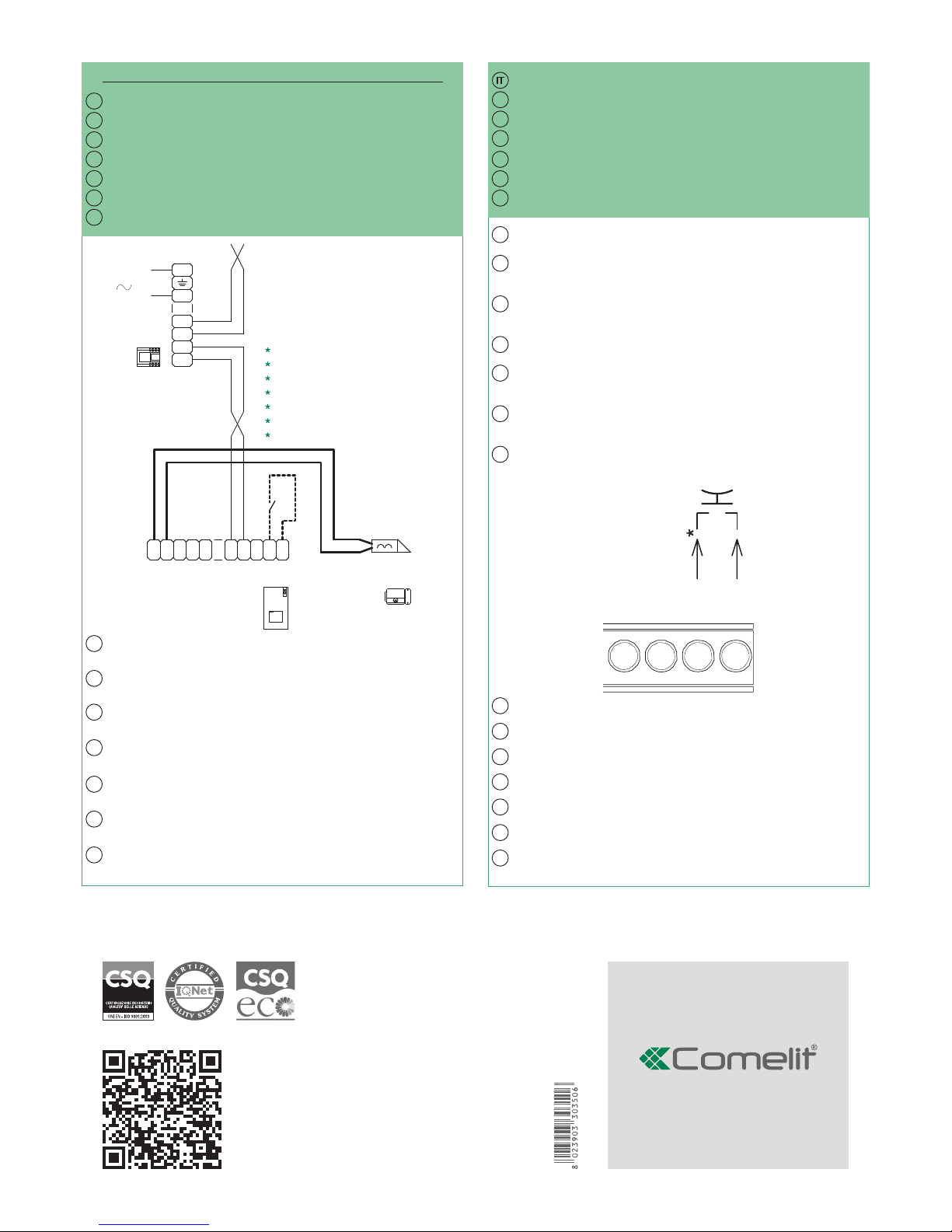
www.comelitgroup.com
Passion.Technology.Design.
2ª edizione Rev.2 10/2015
cod. 2G40001372
EN
FR
NL
DE
ES
PT
IT
IT
DE
DE
ES
FR
FR
PT
PT
EN
EN
ES
ES
PT
NL
NL
LL
O
D
E
T
R
NO
SE
-
SE
+
NC C
M
O
C
1209
L
N
110-240V
L2
L2
L1
L1
4893
*
IT
EN
FR
NL
DE
ES
PT
MNK/DO
Variante collegamento chiamata fuori porta
IT
In caso di più citofoni o stae monitor con lo stesso codice utente collegare il
pulsante CFP su uno solo; tutti i dispositivi suoneranno contemporaneamente.
* 20 m MAX - Utilizzare cavo schermato per il collegamento e non far passare i cavi in
prossimità di carichi induttivi pesanti o cavi di alimentazione (230V / 400V).
In impianti con Art. 1405 è possibile utilizzare la funzione “segnalazione porta aperta”
solo su posto esterno secondario. In impianti con Art. 1404 non è possibile utilizzare la
funzione “segnalazione porta aperta”.
Variante door-open
Pulsante comando apriporta locale
Floor door call connection variant
EN
Where multiple door-entry phones or monitor backplates have the same
user code, connect the CFP button on one only; all the devices will ring
simultaneously.
* 20 m MAX - Use shielded cable for the connection and do not route the cables in the
vicinity of heavy inductive loads or power supply cables (230V/400V).
In systems with Art. 1405 the “door open indication” function can only be used on the
secondary external unit. In systems with Art. 1404 the “door open indication” function
cannot be used.
Door-open variant
Local lock release button
Variante connexion appel palier
FR
Si plusieurs combinés audio ou étriers de moniteur présentent le même code d’appel,
connecter le bouton CFP sur un seul : tous les dispositifs sonneront simultanément.
* 20 m MAX - Pour la connexion, utiliser un câble blindé et ne pas faire passer les câbles à
proximité de charges inductives lourdes ou de câbles d’alimentation (230V / 400V).
Sur les installations disposant de l’Art. 1405, il est possible d’utiliser la fonction « signalisation porte
ouverte » uniquement sur le poste extérieur secondaire. Sur les installations disposant de l’Art.
1404, il n’est pas possible d’utiliser la fonction « signalisation porte ouverte ».
Variante ouvre-porte
Bouton ouvre-porte sortie
Variant met aansluiting van een etagebel
NL
Bij meerdere deurtelefoons of monitor-muurplaten met dezelfde gebruikerscode moet de
knop CFP op slechts één code worden aangesloten; alle toestellen gaan dan tegelijk over.
* 20 m MAX - Gebruik een afgeschermde kabel voor deze verbinding en voer de kabels
niet in de buurt van hooginductieve belastingen of voedingskabels (230V / 400V).
Bij systemen met Art. 1405 is het mogelijk de functie “signalering deur open” alleen op het
secundaire deurstation te gebruiken. Bij systemen met Art. 1404 is het niet mogelijk de
functie “signalering deur open” te gebruiken.
Variant door-open
Lokale bedieningsknop deuropener
Anschlussvariante Rufsignale der Außensprechstellen
DE
Im Fall mehrerer Innensprechstellen oder Monitorgrundplatten mit demselben
Benutzercode die CFP Taste nur an ein Gerät anschließen; sämtliche Geräte werden
gleichzeitig klingeln.
. * 20 m MAX. - Zur Verbindung ist ein geschirmtes Kabel zu verwenden; die Kabel dürfen nicht in der Nähe
von großen induktiven Belastungen oder von Kabeln zur Stromversorgung (230V/400V) verlegt werden.
In Anlagen mit Art. 1405 kann die Funktion “Anzeige Tür geönet” nur in der zusätzlichen
Außensprechstelle benutzt werden. In Anlagen mit Art. 1404 kann die Funktion “Anzeige Tür geönet”
nicht benutzt werden.
Variante Tür-offen
Taste lokaler Türöner
Variante con conexión para llamada timbre de planta
En caso de varios telefonillos o placas soporte de monitor con el mismo código de
usuario, conectar el pulsador CFP a uno solo; todos los dispositivos se activarán al
mismo tiempo.
* 20 m MÁX. - Utilizar cable blindado para la conexión y no tender los cables cerca de cargas
inductivas pesadas o cables de alimentación (230 V / 400 V).
En instalaciones con el art. 1405 es posible utilizar la función de señalización de puerta abierta
únicamente en la placa externa secundaria. En instalaciones con el art. 1404 no es posible utilizar
la función de señalización de puerta abierta.
Variante puerta abierta
Pulsador abrepuertas local
Variante para ligação da campainha externa
L
L
CFP
CFP
Caso existam mais telefones intercomunicadores ou suportes de monitor com
o mesmo código de utilizador, ligar o botão CFP apenas a um deles; todos os
dispositivos tocam simultaneamente.
* 20 m MÁX. - Usar cabo blindado para a ligação e não fazer passar os cabos na
proximidade de cargas indutivas pesadas ou cabos de alimentação (230 V/400 V).
Em instalações com o art. 1405 é possível utilizar a função “indicação de porta aberta”
apenas no posto externo secundário. Em instalações com o art. 1404 não é possível
utilizar a função “indicação de porta aberta”.
Variante “door-open”
Botão de comando de abertura da porta local
 Loading...