

Page 1
EN
TECHNICAL
MANUAL
Digital call module
Art. 3070S
Passion.Technology.Design.
Page 2

Warning
Intended use
This Comelit product was designed for use in the creation of audio and video communication systems in residential,
commercial or industrial settings and in public buildings or buildings used by the public.
Installation
All activities connected to the installation of Comelit products must be carried out by qualified technical personnel, with
careful observation of the indications provided in the Manuals / Instruction sheets supplied with those products.
Wires
Cut o the power supply before carrying out any maintenance procedures.
Use wires with a cross-section suited to the distances involved, observing the instructions provided in the system
manual.
We advise against running the system wires through the same duct as the power cables (230V or higher).
Safe usage
To ensure Comelit products are used safely:
• carefully observe the indications provided in the Manuals / Instruction sheets
• make sure the system created using Comelit products has not been tampered with / damaged.
Maintenance
Comelit products do not require maintenance aside from routine cleaning, which should be carried out in accordance
with the indications provided in the Manuals / Instruction sheets.
Any repair work must be carried out
• for the products themselves, exclusively by Comelit Group S.p.A.,
• for systems, by qualified technical personnel.
Disclaimer
Comelit Group S.p.A. does not assume any responsibility for
• any usage other than the intended use
• non-observance of the indications and warnings contained in this Manual / Instruction sheet.
Comelit Group S.p.A. nonetheless reserves the right to change the information provided in this Manual / Instruction
sheet at any time and without prior notice.
Table of contents
Warning ............................................................................................ 2
Description ....................................................................................... 3
Technical features ........................................................................... 4
Connections ..................................................................................... 5
Connection to earth of 3070S .................................................................5
Connection to computer .........................................................................5
Connection in Building Kit and SB2 systems ........................................6
Connection in SBTOP and SB1 systems ...............................................6
Program and Operation .................................................................. 7
Navigation mode ......................................................................................7
Self-testing................................................................................................8
Call mode testing ................................................................................8
Setting the language ...........................................................................9
Using the digital module ..........................................................................9
Calling a user ......................................................................................9
Ending a call/conversation................................................................10
Opening the door by entering the password code ...........................10
Accessing/exiting the configuration stage ..........................................11
1. Settings ...............................................................................................12
1.1. System parameters ....................................................................12
1.1.1. Speaker parameters ........................................................12
1.1.2. Download type [NO VIP] .................................................13
1.1.3. Call mode ........................................................................14
1.1.4. RS485 address [NO VIP] ................................................16
1.2. Language ...................................................................................16
1.3. Default settings ..........................................................................17
2. Access control ....................................................................................18
2.1. Supercode .................................................................................18
2.1.1. Change ............................................................................18
2.1.2. Default settings ................................................................18
2.2. Password ...................................................................................19
2.2.1. Enter ................................................................................19
2.2.2. Delete ..............................................................................19
2.2.3. Delete all .........................................................................20
3. Info .......................................................................................................20
Data management using 1249B [NO VIP] ............................................21
Entering a list (download)..................................................................21
Reading (upload) of the stored list ....................................................21
Navigation tree .......................................................................................22
System performance and layouts ................................................ 23
2
Page 3
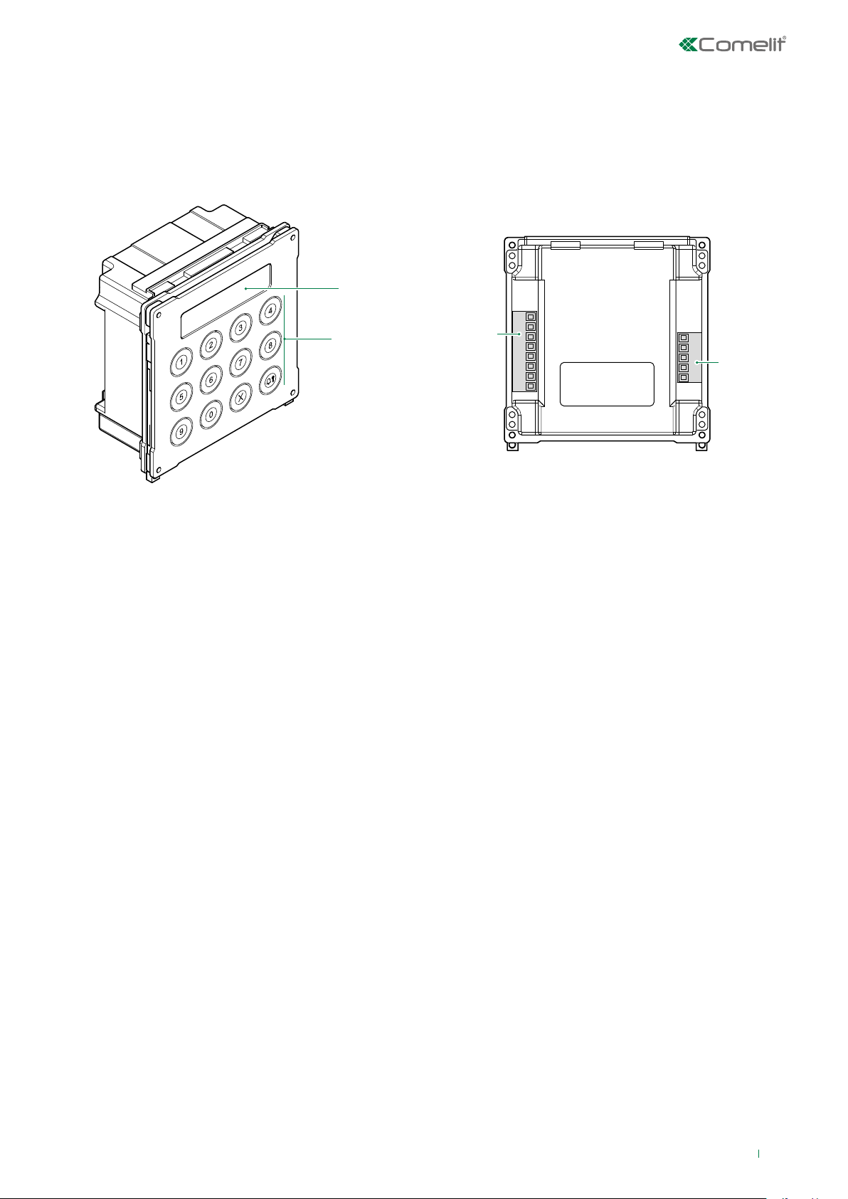
Description
Vandalcom series digital call module made using double 2.5 mm 316 stainless steel plate, complete with 12-button backlit
keypad plus 16-character alphanumerical display for showing call codes and interactive user messages (engaged, etc.). Also
functions as an electronic key code device with a possible 1000 different 6-digit codes. For use in Building kit, SBTOP, SB1
audio, SB2 audio and ViP systems.
1.
1. LCD screen
2. Alphanumeric keys
Terminal block for MR1 connection
V+ V- DC power supply
12~ 12~ AC power supply
S serial port
- reference negative
PR programming input
- reference negative
Terminal block for MR2 connection
D+ RS485 connection
D- RS485 connection
- reference negative
RX RS232 connection
TX RS232 connection
2.
MR1
MR2
3
Page 4

Technical features
Vandal Resistant rating (IK code) Yes
Operating temperature (°C) -25 ÷ +55
Maximum current absorption (mA) 100
SOFTWARE/FIRMWARE SPECIFICATIONS
HARDWARE SPECIFICATIONS
Simplebus Top audio/video system Yes
Building Kit audio/video system Yes
Simplebus 2 audio system Yes
Simplebus 1 audio system Yes
MAIN FEATURES
Backlighting color Green led
Product height (mm) 106
Product width (mm) 106
Product depth (mm) 56
No. user codes 1000
FUNCTIONS
Key button function Yes
Total buttons 12
COMPATIBILITY
Vip system Yes
MOUNTING/INSTALLATION
Flush-mounted Yes
Wall-mounted Yes
AUDIO/VIDEO FEATURES
Display resolution (H x V) 16x2 characters
CONNECTIVITY
Type of connections/ports RS232, RS485
RS232 ports 1
RS485 ports 1
4
Page 5
Connections
1195
3072S 3072S
3070S
3072S
COMPUTER
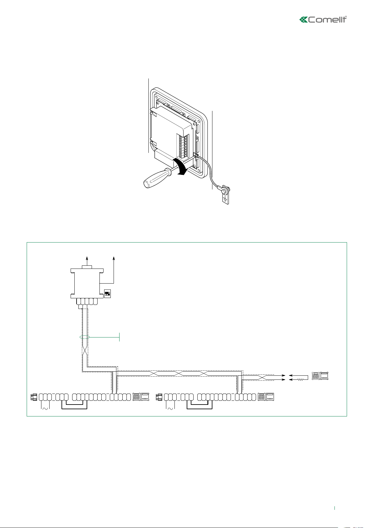
Connection to earth of 3070S
To prevent any interference caused by electrostatic discharges, it is advisable to screen the casing as shown in the diagram
Connection to computer
MOXA
TCC-80
2
241
3
0
2
0
0
20022618
G
D
N
-
D
12
VV
+
-
D
+
~12~
-
T T
S
ON
123
+
P
-
-
USB
ALIM.
5V
Braided, shielded telephone cable
1195
T
R
D
-
X
XR
+
3070S
2
3
0
0
D
-
D
120E
1/4W
2
VV
0
+
214
-
12~12
S
~
P
-
-
R X
R-T
D
DD
X
+
3070S
It is possible to use up to 5 terminals Art. 3070S-3072S
Maximum distance between l’Art. 20022618 and furthest terminal Art. 3070S-3072S: 100m
5
Page 6
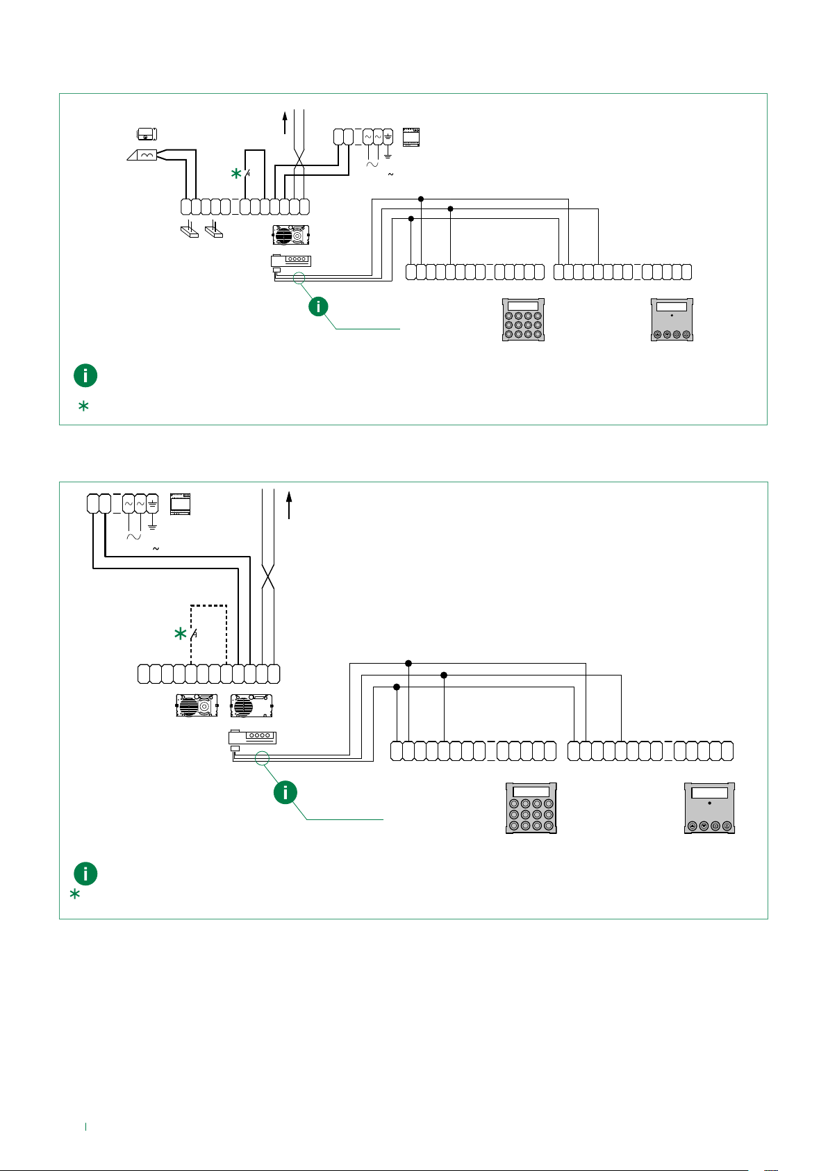
Connection in Building Kit and SB2 systems
1210
+
-
120-230 V
C
G
R
D
SE-SE
O
+
M
J9 J11
NC
NO
1621VC
N
D
4681
1621
VV
T
O
LL
+
-
E
J1
J2
"V-" BLUE
"S" YELLOW
"V+" BROWN
2E7T000696
Use the cable 2E7T000696 supplied with Art. 3070S and Art. 3072S
Local lock-release button.
Connection in SBTOP and SB1 systems
1595
T
P
12~12
VV
S
-
+
-
-
~
R
D
-
+ +
-
VV
X
XR
+
-
12~12
~
P
S
-
-
R X
3070S
R-T
D
DD
X
-
3072S
+
-
1595
VIDEO ENTRY SYSTEM RISER
120-230 V
C
S
O
NC
NO
E
M
R
G
D
VV
T
N
RPO
D
E
LL
+
-
4680C
1622VC
1622VCF
1622
J1
12~12
J2
VV
+
S
-
~
"V-" BLUE
"S" YELLOW
"V+" BROWN
2E7T000696
Use the cable 2E7T000696 supplied with Art. 3070S and Art. 3072S.
Local lock-release button.
T
P
-
-
R
D
-
X
XR
+ +
-
12~12
VV
+
-
S
-
~
P
-
R X
3070S
R-T
D
DD
X
-
3072S
6
Page 7
Program and Operation
The Comelit digital call module Art. 3070S can be used in Building kit, SBTOP, SB1 audio, SB2 audio and ViP systems, and is
fitted with a numeric keypad to call door-entry phone users by entering the code which identifies them.
The main characteristics are as follows:
• Memory capacity for Simplebus systems: 1000 directory entries of 16 numeric characters.
• 32-character numeric display.
• Option of changing the parameters: Door lock time, Audio time and Reset time for the speaker module (reset time
adjustment is not available in VIP mode).
• ACCESS CONTROL function for opening the door by keying in a pre-recorded password code.
• 5 call management modes (see “1.1.3. Call mode”):
• Standard Simplebus (default),
• Simplebus Indirect code,
• Simplebus Top,
• Simplebus Top Indirect code.
• VIP
• Entering the list of users (Download) via connection to PC equipped with software Art.1249B.
• Entering the list of users via connection with the PC can be performed over an RS232 line or over an RS485 line by means
of the interface card Art. 20022618 (see “Connection to computer”).
• Reading (Upload) the list of users stored on the directory module via connection to PC equipped with software Art.1249B.
• Option of displaying graphics interface messages in one of 12 available languages (Italian, English, French, German,
Portuguese, Danish, Finnish, Dutch, Spanish, Swedish, Polish and Norwegian).
• Welcome message management (only available in VIP mode and programmable via VIP Manager) [NOT SIMPLEBUS, NOT
SIMPLEBUS TOP]
• Screensaver (only available in VIP mode and programmable via VIP Manager) [NOT SIMPLEBUS, NOT SIMPLEBUS TOP]
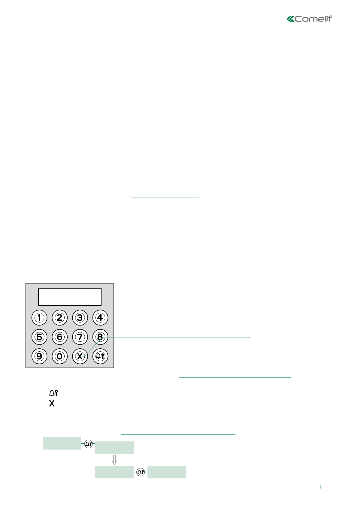
Navigation mode
DELETE/CANCEL
BACK: exit sub-menu
CALL – DOOR LOCK – MENU SELECTION
√ Access to the configuration stage has been carried out (see “Accessing/exiting the configuration stage”).
» The menus are scrolled through automatically every 2 seconds.
f Press
f Press
EXAMPLE: Accessing “language” parameter modification
f access configuration mode (see “Accessing/exiting the configuration stage”z).
to confirm the selection.
to return to the menu level above.
MAIN
SETTINGS
SETTINGS
SYSTEM PARAM
SETTINGS
LANGUAGE
2 sec
LANGUAGE
DEFAULT
7
Page 8
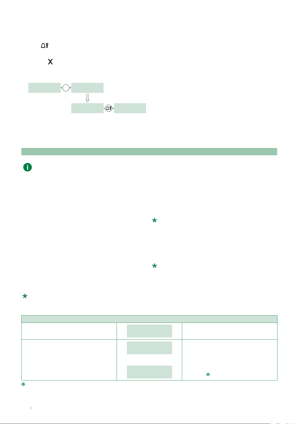
A new parameter is entered by scrolling through the possible values using the number keys.
1. Press the number corresponding to the desired value (in the example 0 = Italian).
» after 2 sec. the parameter corresponding to the entered number appears on screen.
2. Press
to confirm the parameter.
f Press another number to change your selection.
f Press
to return to the menu level above.
EXAMPLE: “italiano” selected as language
LANGUAGE
DEFAULT
0
LANGUAGE
_ _ _ 0
2 sec
LANGUAGE
ITALIANO
PARAMETER
CHANGED
Self-testing
Call mode testing
When the device is switched on, it performs a test to check the type of system configured on the speaker (Simplebus,
Simplebus Top or VIP).
If the digital call module is new (or if the parameters have been restored to the default values):
• if the module is connected to a VIP system
» the module aligns with the speaker, self-configuring in “VIP call mode”, and receives all the information and data stored
on the speaker;
• if the module is connected to an SB TOP system
» he first call mode display screen shows the string ERROR
• if the module is connected to an SB system
» the first call mode display screen shows the string SIMPLEBUS.
.
If the digital call module has a directory already containing data:
• if the directory and speaker are configured dierently:
» he first call mode display screen shows the string ERROR
.
• if the directory and speaker are aligned:
» the first checking screen will show the system type SB / SB TOP / VIP.
Follow the procedure described in “1.1.3. CALL MODE” if you want to align the directory module with the type of
system configured on the speaker.
INITIAL CONDITION
Module powered up
CALL MODE
PLEASE WAIT
CALL MODE
SIMPLEBUS
The message PLEASE WAIT indicates selftesting in progress.
At the end of self-testing the type of system
set is displayed (SIMPLEBUS by default).
or:
CALL MODE
ERROR
If the directory and speaker are configured
dierently.
Follow the procedure described in “1.1.3. CALL MODE” if you want to align the directory module with the type of
system configured on the speaker.
8
Page 9
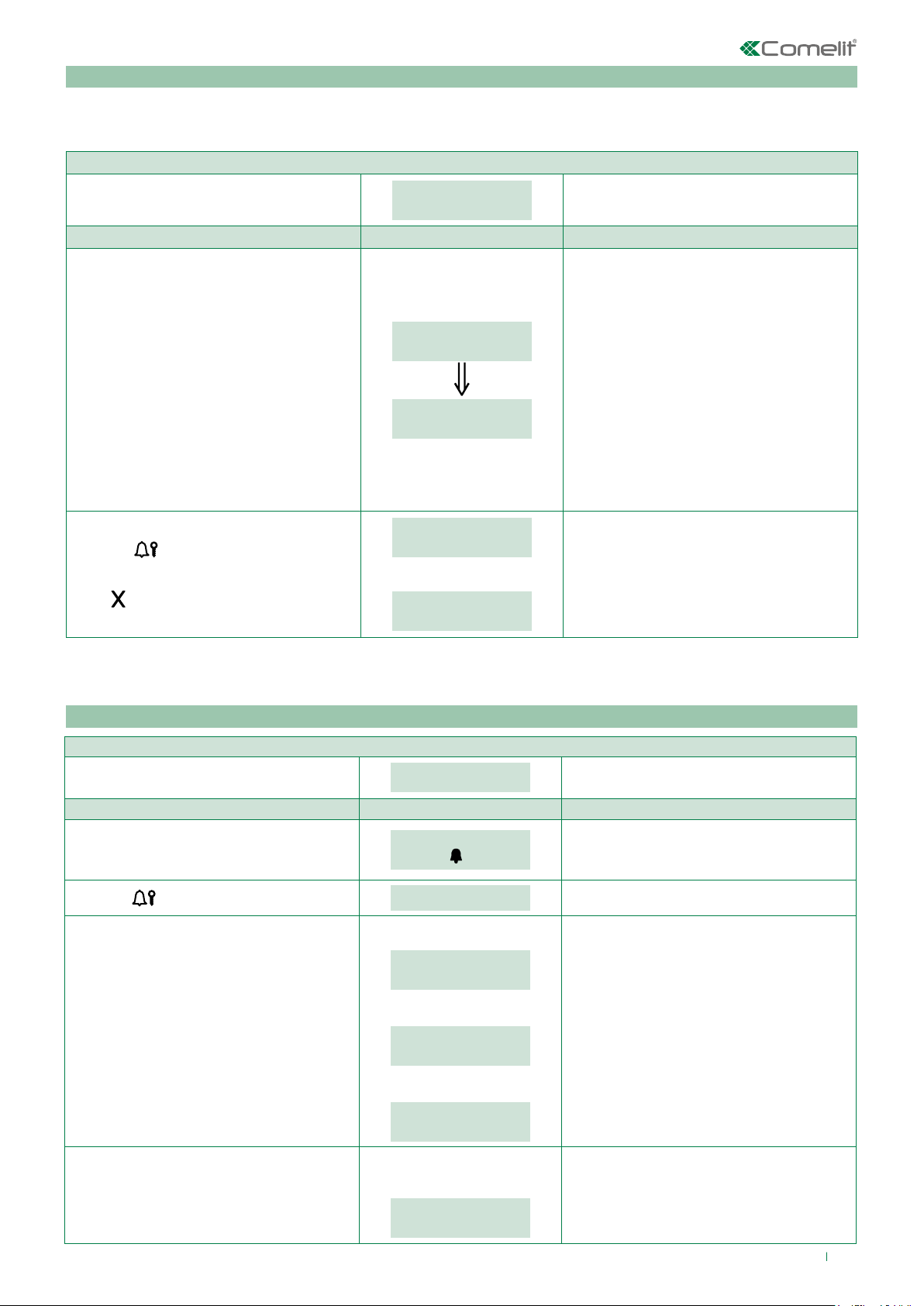
Setting the language
If the LANGUAGE parameter is set to DEFAULT.
During startup (after call mode testing), you will be asked to select the operating language.
INITIAL CONDITION
PROCEDURE DISPLAY INFO DESCRIPTION
Select the operating language by entering
the corresponding number:
0 = ITALIANO
1 = ENGLISH
2 = FRANÇAIS
3 = DEUTSCH
4 = PORTUGUES
5 = DANSK
6 = SUOMI
7 = NEDERLANDS
8 = ESPAÑOL
9 = SVENSKA
10 = POLSKI
11 = NORSK
12 = DEFAULT(italian)
Press the
of the parameter.
Press
key to confirm the value
to exit the selected language.
LANGUAGE
DEFAULT
LANGUAGE
_ _ _ 1
LANGUAGE
ENGLISH
PARAMETER
CHANGED
or:
ERROR
2 sec
The current value of the parameter appears
on screen.
N.B. If the LANGUAGE parameter is set
to DEFAULT, you will be asked to set the
language again at the next startup.
If entry is successful.
If entry does not fall within the limits.
Using the digital module
Calling a user
Module powered up in standby.
PROCEDURE DISPLAY INFO DESCRIPTION
Enter code using the numeric keypad on
module Art. 3070S.
Press the
key to call.
INITIAL CONDITION
ENTER USER CODE
_ _ 1
PRESS
TO CALL
PLEASE WAIT
If the call
was successful you will see:
CALL
EFFECTED
If the call was not
successful you will see:
CALL
FAILED
Or if the riser
is busy you will see:
BUSY
USER
EXAMPLE: calling a user with code 1.
If the call
is successful and the user
answers you will see:
COMMUNICATING...
9
Page 10
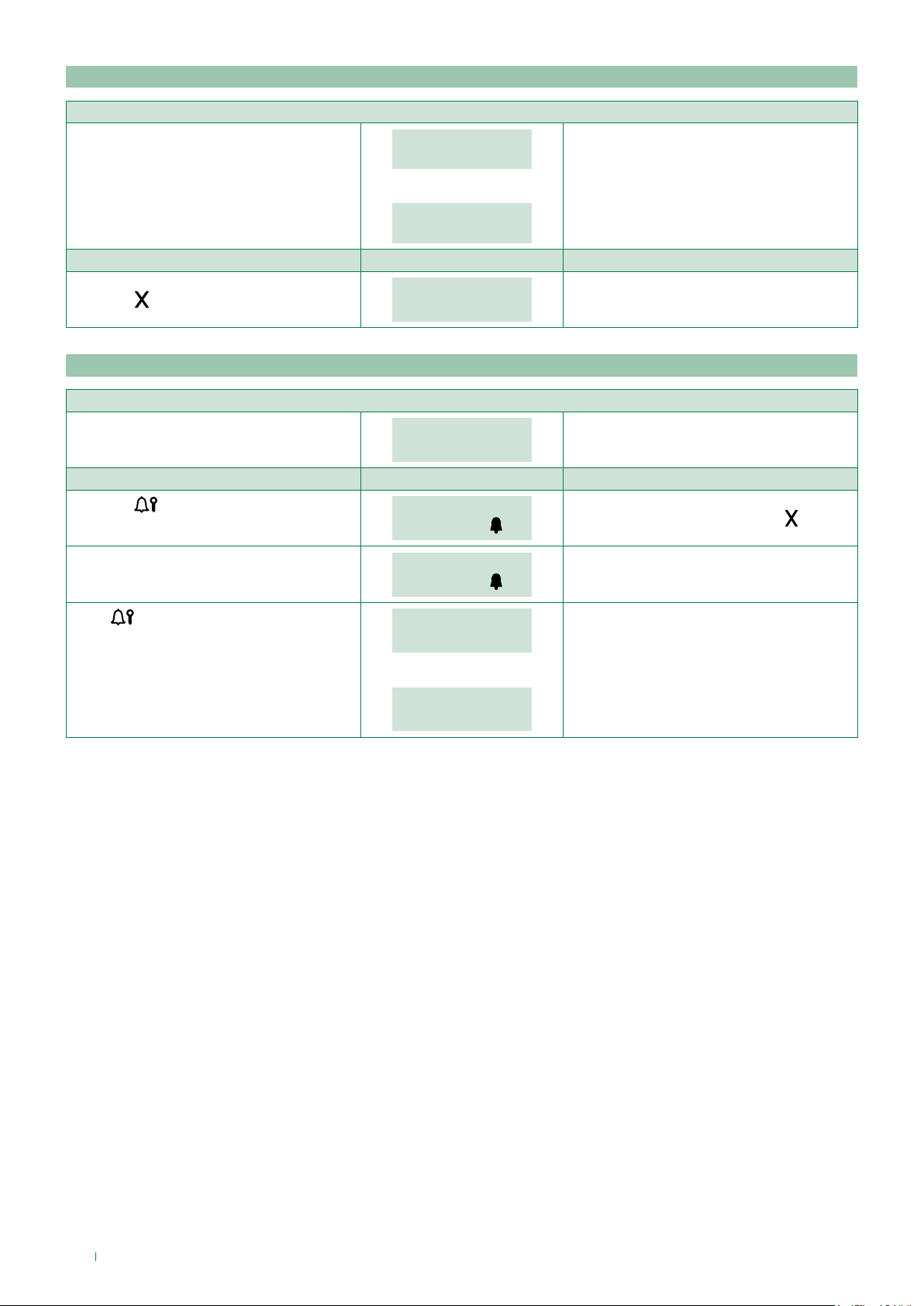
Ending a call/conversation
INITIAL CONDITION
PROCEDURE DISPLAY INFO DESCRIPTION
Press the
Opening the door by entering the password code
Press the
Enter the password code. (min. 4 characters).
Press
. key
PROCEDURE DISPLAY INFO DESCRIPTION
key.
to confirm.
CALL
EFFECTED
Or:
COMMUNICATING...
END OF
COMMUNICATION
INITIAL CONDITION
ENTER
USER CODE
PASSWORD: _ _ _ _ _ _
CONFIRM WITH
PASSWORD: _ _ * * * *
CONFIRM WITH
DOOR
OPEN
or:
Call eected.
Conversation in progress.
Standby
To cancel the procedure press the . key
If the password is 4-5 characters long, it will
self-complete: the first digits will be zero
(e.g.: 001234 / 012345).
If the password code is already in the
memory. The contact on the speaker module
will be activated.
WRONG
PASSWORD
If the password code does not exist in the
memory.
10
Page 11
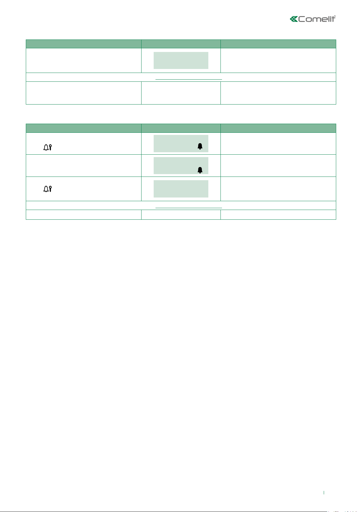
Accessing/exiting the configuration stage
PROCEDURE DISPLAY INFO DESCRIPTION
Connect terminal PR to terminal –
and power up the module.
Configure the parameters you wish to change...(see “1.1. System parameters”)
After configuration is complete, cut o the
power supply and remove the connection
between PR and –.
Or:
PROCEDURE DISPLAY INFO DISPLAY INFO
In standby.
Press
.
PASSWORD: _ _ _ _ _ _
MAIN
SETTINGS
CONFIRM WITH
The module is in programming mode.
The menus are scrolled through
automatically every 2 seconds.
The module has exited programming mode.
Login screen.
Enter the supercode (default = 778899).
PASSWORD:
CONFIRM WITH
******
MAIN
Press
Configure the parameters you wish to change...(see “1.1. System parameters”)
Wait 30 sec. The module has exited programming mode.
to confirm.
SETTINGS
If the supercode is 4-5 characters long, it
will self-complete: the first digits will be zero
(e.g.: 001234 / 012345).
The module is in programming mode.
The menus are scrolled through
automatically every 2 seconds.
11
Page 12
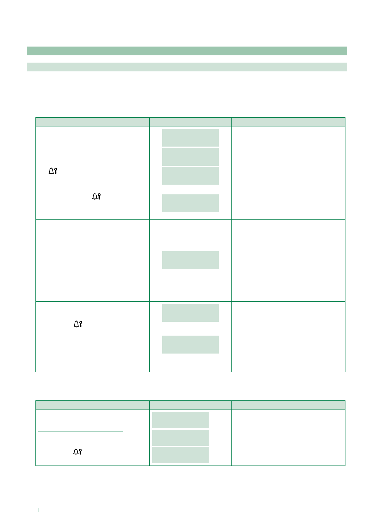
1. Settings
1.1. System parameters
1.1.1. Speaker parameters
This procedure can be used to:
A. Change the audio time audio times (t AUDIO)
B. Change the door lock time the door lock relay closure time (t DOOR LOCK)
C. Change the reset time [NOT VIP] the speaker module reset time once door-entry phone communication has ended (t
RESET)
PROCEDURE DISPLAY INFO DESCRIPTION
SETTINGS
Access configuration (see “Accessing/
exiting the configuration stage”)
Select the menu SETTINGS / SYSTEM
PARAM. / SPEAKER PARAM. using the
key
.
SYSTEM PARAM.
SYSTEM PARAM.
SPEAKER PARAM.
SPEAKER PARAM.
ENTER t AUDIO
The menus are scrolled through
automatically every 2 seconds.
Select, using the key
for the parameter you want to change. (t
AUDIO, t DOOR LOCK, t RESET)
To change the parameter, enter a new
value.
Press the key
of the parameter.
Exit configuration (see “Accessing/exiting
the configuration stage”)
the menu option
to confirm the value
ENTER t AUDIO
0010
ENTER t AUDIO
_ _ 20
PARAMETER
CHANGED
or:
ERROR
EXAMPLE: Changing the conversation
time.
The minimum (not current) value of the
parameter appears on screen.
Choose a value that falls within the
following limits:
[SB] [SB TOP]
t AUDIO (10-180)
t DOOR LOCK (1-8)
t RESET (1-10)
[VIP]
t AUDIO (30-600)
t DOOR LOCK (1-60)
If entry is successful.
If entry does not fall within the limits.
D. Viewing [NO VIP] This procedure can be used to view the audio time, door lock relay closure time and reset time for the
speaker module, plus the call mode.
PROCEDURE DISPLAY INFO DESCRIPTION
Access configuration (see “Accessing/
exiting the configuration stage”) Select
the menu SETTINGS / SYSTEM PARAM. /
SPEAKER PARAM. / VIEWING
using the key
12
.
SETTINGS
SYSTEM PARAM.
SYSTEM PARAM.
SPEAKER PARAM.
SPEAKER PARAM.
VIEWING
The menus are scrolled through
automatically every 2 seconds.
Page 13
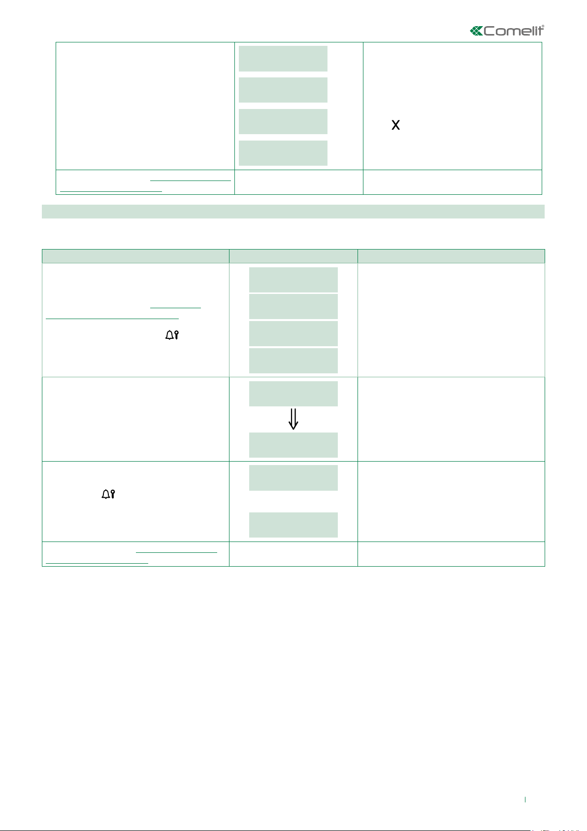
AUDIO TIMING
0020
DOOR LOCK TIME
0002
The parameter values are displayed
automatically every 2 seconds.
RESET TIME
0010
Press
CALL MODE
SIMPLEBUS
Exit configuration (see “Accessing/exiting
the configuration stage”)
1.1.2. Download type [NO VIP]
The parameter sets the type of connection (RS232 or RS485) used for data management.
PROCEDURE DISPLAY INFO DESCRIPTION
Access configuration (see “Accessing/
exiting the configuration stage”) Select
the menu SETTINGS / SYSTEM PARAM. /
DOWNLOAD TYPE using the
key.
MAIN
SETTINGS
SETTINGS
SYSTEM PARAM.
SYSTEM PARAM.
DOWNLOAD TYPE
DOWNLOAD TYPE
RS232
The menus are scrolled through
automatically every 2 seconds.
The currently configured value appears on
screen.
o exit speaker parameter viewing.
Select the download type by entering the
corresponding number:
0 = RS232
1 = RS485
Press the key
to confirm the value
of the parameter.
Exit configuration (see “Accessing/exiting
the configuration stage”)
DOWNLOAD TYPE
_ _ _ 1
2 sec
DOWNLOAD TYPE
RS485
PARAMETER
CHANGED
or:
ERROR
EXAMPLE: Changing the download type.
If entry is successful.
If entry does not fall within the limits.
13
Page 14

1.1.3. Call mode
There are 5 call management modes to choose from:
• Standard Simplebus (default),
• Simplebus Indirect code,
• Simplebus Top,
• Simplebus Top Indirect code,
• VIP
A. SIMPLEBUS - STANDARD call mode (default)
In this operating mode, the door-entry phone user is identified by a Code field no longer than 3 digits (between 1 and 240).
The call is made as follows:
1. On the keypad, enter the code 1
2. Press the key
» transmit the call to the user identified with the code 1
B. SIMPLEBUS - INDIRECT CODE call mode
In this operating mode, the door-entry phone user is identified by an Indirect Code field no longer than 6 digits and a
Code field no longer than 3 digits (between 1 and 240).
Example
User identified by Code = 1 and Indirect Code = 1000
The call is made as follows:
1. On the keypad, enter the code 1000
2. press the key
» transmit the call to the user identified with the code 1
C. SIMPLEBUS TOP call mode
In this operating mode, the door-entry phone user is identified by a 2-part Code field; a zone field with up to 3 digits
between 1 and 500) and a user field which must have 3 digits (between 1 and 240).
The call is made as follows:
1. On the keypad, enter the code 25 015
2. press the key
» call transmitted to the user identified with the code 25 015
D. SIMPLEBUS TOP – INDIRECT CODE call mode
In this operating mode, the door-entry phone user is identified by an Indirect Code field no longer than 6 digits and
a 2-part Code field; a zone field with up to 3 digits between 1 and 500) and a user field which must have 3 digits
(between 1 and 240).
Example
User identified by Code = 25 015 and Indirect Code = 1000
The call is made as follows:
1. On the keypad, enter the code 1000
2. press the key
.
» call transmitted to the user identified with the code 25 015
E. VIP call mode
In this operating mode the door-entry phone user is identified with a VIP address (max. 8 digits; for code self-
completion please refer to the technical manual for VIP Manager software).
Address entry on the speaker is managed using VIP Manager software.
The call is made as follows:
1. On the keypad, enter the code 56
2. press the key
» transmit the call to the user identified with the code 56
14
Page 15
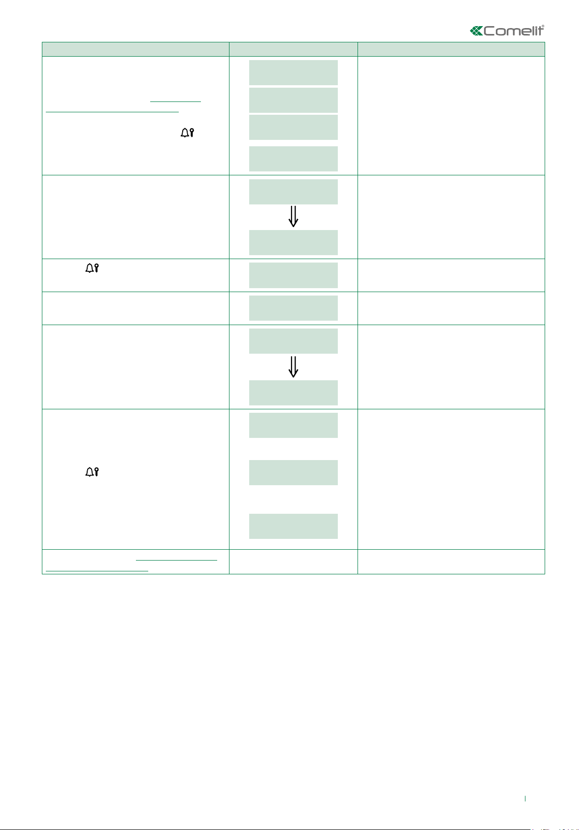
PROCEDURE DISPLAY INFO DESCRIPTION
Access configuration (see “Accessing/
exiting the configuration stage”)
Select the menu SETTINGS / SYSTEM
PARAM. / CALL MODE using the
key.
MAIN
SETTINGS
SETTINGS
SYSTEM PARAM.
SYSTEM PARAM.
CALL MODE
CALL MODE
SIMPLEBUS
The menus are scrolled through
automatically every 2 seconds.
The current value of the parameter appears
on screen (Simplebus, Simplebus Top, VIP).
Select the call mode by entering the
corresponding number:
0 = SIMPLEBUS
1 = SIMPLEBUS TOP
2 = VIP
Press the
key to confirm the value
of the parameter.
Select the call mode by entering the
corresponding number:
0 = STANDARD
1 = INDIRECT CODE
[NO VIP]
CALL MODE
_ _ _ 1
2 sec
CALL MODE
SIMPLEBUS TOP
PLEASE WAIT
CALL MODE
STANDARD
CALL MODE
_ _ _ 1
2 sec
CALL MODE
INDIRECT CODE
PARAMETER
CHANGED
or:
EXAMPLE: setting the system as
SIMPLEBUS TOP
If the change was successful the speaker will
emit a confirmation tone.
The current value of the parameter appears
on screen (Standard or indirect code).
EXAMPLE: setting the call mode as
INDIRECT CODE.
If entry is successful.
Press the
key to confirm the value
of the parameter.
Exit configuration (see “Accessing/exiting
the configuration stage”)
ERROR
or:
ERROR
DEFAULT SETTINGS
If entry does not fall within the limits.
If the directory and speaker are
configured differently and the directory
already contains data, the default values
must be restored.
15
Page 16
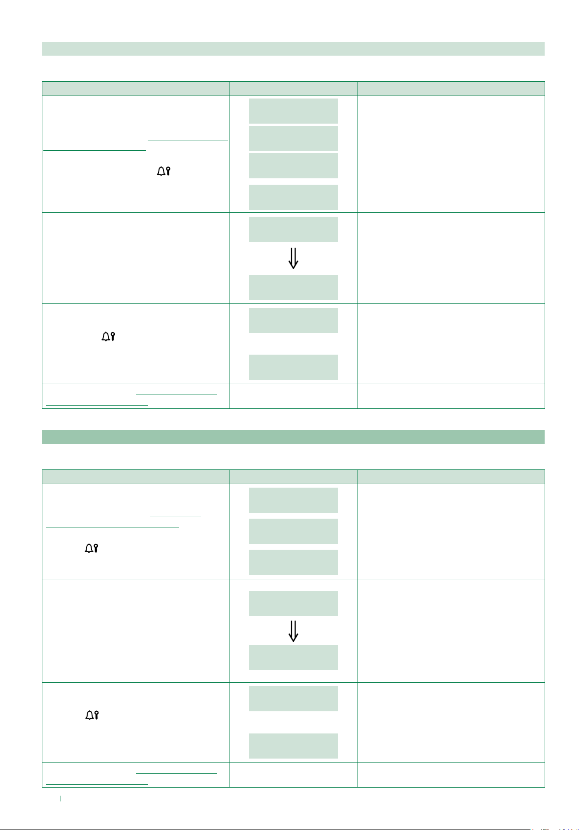
1.1.4. RS485 address [NO VIP]
The value of this parameter is used only in special applications.
PROCEDURE DISPLAY INFO DESCRIPTION
MAIN
SETTINGS
Access configuration (see “Accessing/exiting
the configuration stage”)
Select the SETTINGS / SYSTEM PARAM. /
ADDRESS RS485 using the
key.
SETTINGS
SYSTEM PARAM.
SYSTEM PARAM.
ADDRESS RS485
ADDRESS RS485
0000
ADDRESS RS485
_ 250
The menus are scrolled through
automatically every 2 seconds.
The current value of the parameter appears on
screen.
Enter the RS485 address: from 0 to 255.
2 sec
EXAMPLE: Entering address 250.
RS485
0250
Press the key
to confirm the value
PARAMETER
CHANGED
or:
If entry is successful.
of the parameter.
ERROR
If entry does not fall within the limits.
Exit configuration (see “Accessing/exiting
the configuration stage”)
1.2. Language
The value of this parameter is used to set the language in which messages are displayed.
PROCEDURE DISPLAY INFO DESCRIPTION
MAIN
Access configuration (see “Accessing/
exiting the configuration stage”)
Select the menu SETTINGS / LANGUAGE
using the
key.
SETTINGS
SETTINGS
LANGUAGE
LANGUAGE
The menus are scrolled through
automatically every 2 seconds.
The current value of the parameter appears
on screen.
ENGLISH
Select the operating language by entering
the corresponding number:
0 = ITALIANO / 1 = ENGLISH
2 = FRANÇAIS / 3 = DEUTSCH
4 = PORTUGUES / 5 = DANSK
6 = SUOMI / 7 = NEDERLANDS
8 = ESPAÑOL / 9 = SVENSKA
10 = POLSKI / 11 = NORSK
12 = DEFAULT(italiano)
Press the
key to confirm the value
of the parameter.
Exit configuration (see “Accessing/exiting
the configuration stage”)
16
LANGUAGE
_ _ _ 0
LANGUAGE
ITALIANO
PARAMETER
CHANGED
or:
ERROR
EXAMPLE: Setting the language to English.
2 sec
N.B. If the LANGUAGE parameter is set
to DEFAULT, you will be asked to set the
language again at the next startup.
If entry is successful.
If entry does not fall within the limits.
Page 17
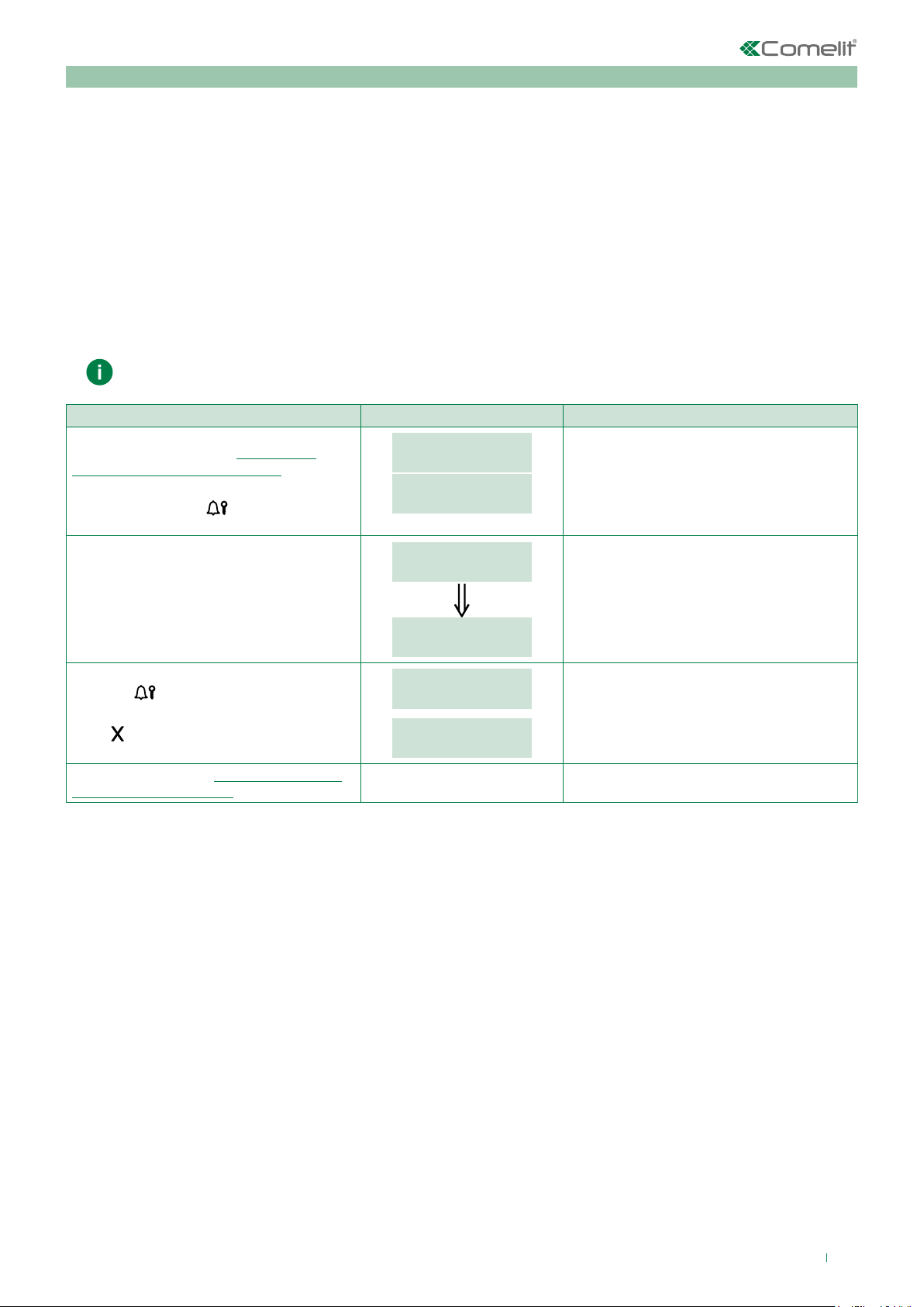
1.3. Default settings
This procedure restores the factory-set default parameters:
Language = DEFAULT;
System type = SIMPLEBUS;
Call type = STANDARD;
Screensaver =disabled (the Screen Saver function can only be programmed for VIP systems using VIP Manager);
RS485 address = 0000;
Download type = RS232;
Supercode = 778899;
Welcome message = disabled (the Welcome message function can only be programmed for VIP systems using VIP
Manager);
Static welcome message = disabled (the Welcome message function can only be programmed for VIP systems using
VIP Manager);
Number of directory entries = 0
Number of password entries = 0
This procedure resets the directory and password database
PROCEDURE DISPLAY INFO DESCRIPTION
Access configuration (see “Accessing/
exiting the configuration stage”)
Select the menu SETTINGS / DEFAULT
SETTINGS using the
key.
MAIN
SETTINGS
SETTINGS
DEFAULT SETTINGS
The menus are scrolled through
automatically every 2 seconds.
The current value of the parameter appears
on screen.
Select the desired value by entering the
corresponding number:
0 = NO
1 = YES
Press the
key to confirm the value of the
parameter.
Press
to exit the menu.
Exit configuration (see “Accessing/exiting
the configuration stage”)
DEFAULT SETTINGS
_ _ _ 1
2 sec
DEFAULT SETTINGS
YES
PLEASE WAIT
If entry is successful.
PARAMETER
CHANGED
17
Page 18
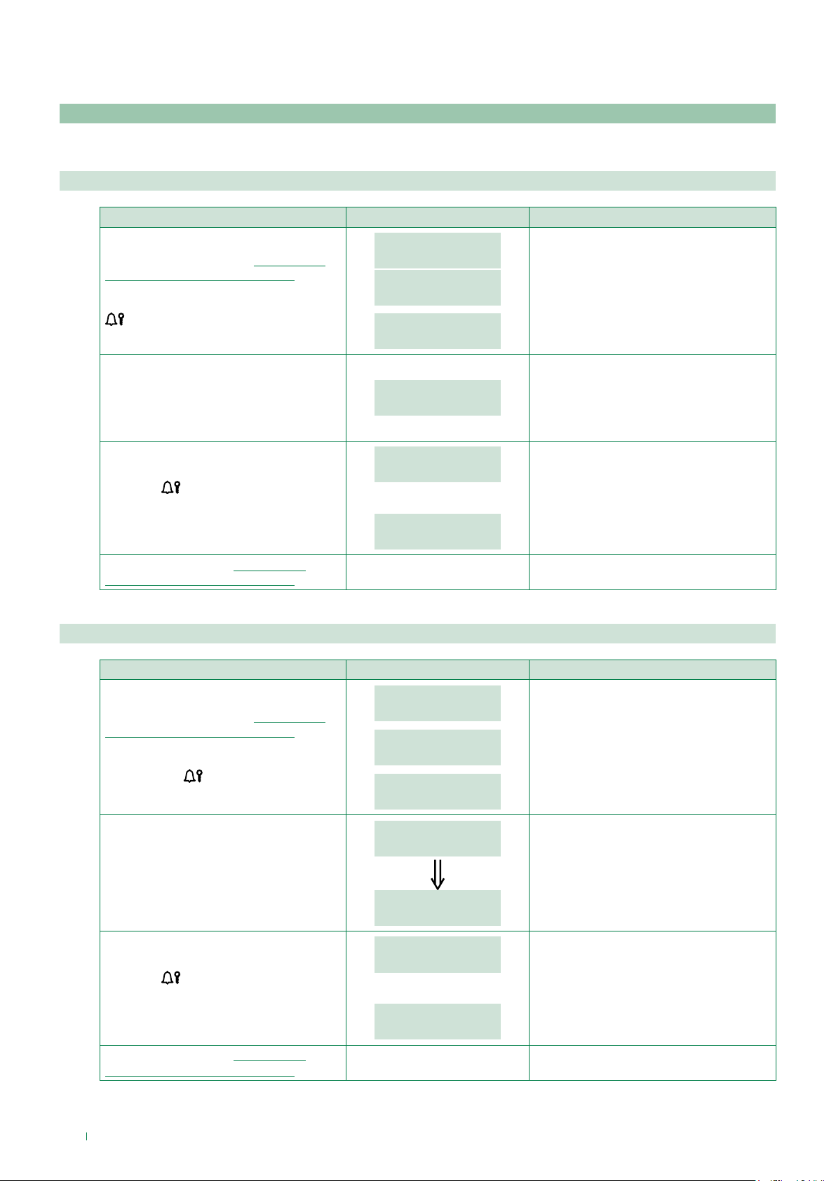
2. Access control
2.1. Supercode
The supercode can be used to access the configuration menu.
2.1.1. Change
PROCEDURE DISPLAY INFO DESCRIPTION
MAIN
Access configuration (see “Accessing/
exiting the configuration stage”)
Select the menu ACCESS CONTROL /
SUPERCODE / CHANGE using the key
.
Enter the new supercode value.
ACCESS CONTROL
ACCESS CONTROL
SUPERCODE
SUPERCODE
CHANGE
SUPERCODE
VALUE: _ _ _ * * *
The menus are scrolled through
automatically every 2 seconds.
The supercode must be at least 4 digits
long.
If the supercode is 4-5 characters long, it
will self-complete: the first digits will be
zero (e.g.: 001234 / 012345).
Press the
of the parameter.
Exit configuration (see “Accessing/
exiting the configuration stage”)
2.1.2. Default settings
Access configuration (see “Accessing/
exiting the configuration stage”)
Select the menu ACCESS CONTROL /
SUPERCODE / DEFAULT SETTINGS
using the key
Select the desired value:
0 = NO
1 = YES
PARAMETER
CHANGED
key to confirm the value
PASSWORD ALREADY
PROCEDURE DISPLAY INFO DESCRIPTION
ACCESS CONTROL
SUPERCODE
SUPERCODE
DEFAULT SETTINGS
.
DEFAULT SETTINGS
NO
DEFAULT SETTINGS
_ _ _ 1
DEFAULT SETTINGS
YES
or:
IN MEMORY
2 sec
If entry is successful.
If the password has already been
entered.
The menus are scrolled through
automatically every 2 seconds.
The current value of the parameter
appears on screen.
default = 778899
18
Press the
of the parameter.
Exit configuration (see “Accessing/
exiting the configuration stage”)
key to confirm the value
PARAMETER
CHANGED
or:
ERROR
If entry is successful.
If entry does not fall within the limits.
Page 19
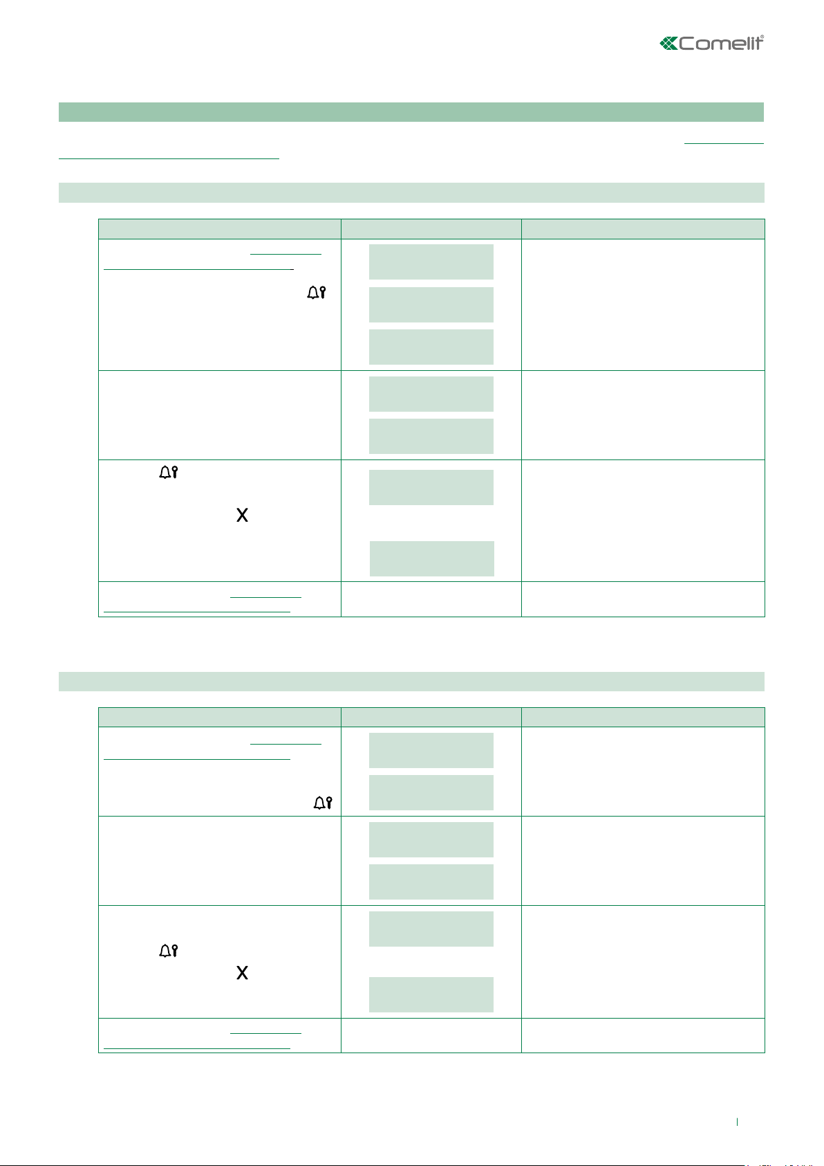
2.2. Password
The door lock relay on the speaker module can be activated by entering a password code stored previously (see “Opening the
door by entering the password code”)
2.2.1. Enter
PROCEDURE DISPLAY INFO DESCRIPTION
Access configuration (see “Accessing/
exiting the configuration stage”)
Select the ACCESS CONTROL /
PASSWORD / ENTER using the key
MAIN
ACCESS CONTROL
.
ACCESS CONTROL
The menus are scrolled through
automatically every 2 seconds.
PASSWORD
PASSWORD
ENTER
Enter the desired password code.
Press the
of the parameter.
To exit the menu, press
Exit configuration (see “Accessing/
exiting the configuration stage”)
2.2.2. Delete
Access configuration (see “Accessing/
exiting the configuration stage”)
Select the menu ACCESS CONTROL /
PASSWORD / DELETE using the key
PASSWORD
VALUE: _ _ _ _ _ _
PASSWORD
The password must be at least 4 digits
long. If the password is 4-5 characters
long, it will self-complete: the first digits
will be zero (e.g.: 001234 / 012345).
VALUE: * * * * * *
key to confirm the value
.
PARAMETER
CHANGED
or:
PASSWORD ALREADY
IN MEMORY
If entry is successful.
Up to 1000 password codes can be
entered.
If the password has already been
entered.
PROCEDURE DISPLAY INFO DESCRIPTION
ACCESS CONTROL
PASSWORD
PASSWORD
The menus are scrolled through
automatically every 2 seconds.
DELETE
Enter the desired password code.
Press the
To exit the menu, press
key to confirm deletion.
.
Exit configuration (see “Accessing/
exiting the configuration stage”)
PASSWORD
VALUE: _ _ _ _ _ _
PASSWORD
VALUE: * * * * * *
PARAMETER
CHANGED
or:
WRONG
PASSWORD
Enter the exact password (the first two
digits, if omitted, will be entered as zero).
If entry is successful.
If the password is not recognised.
19
Page 20
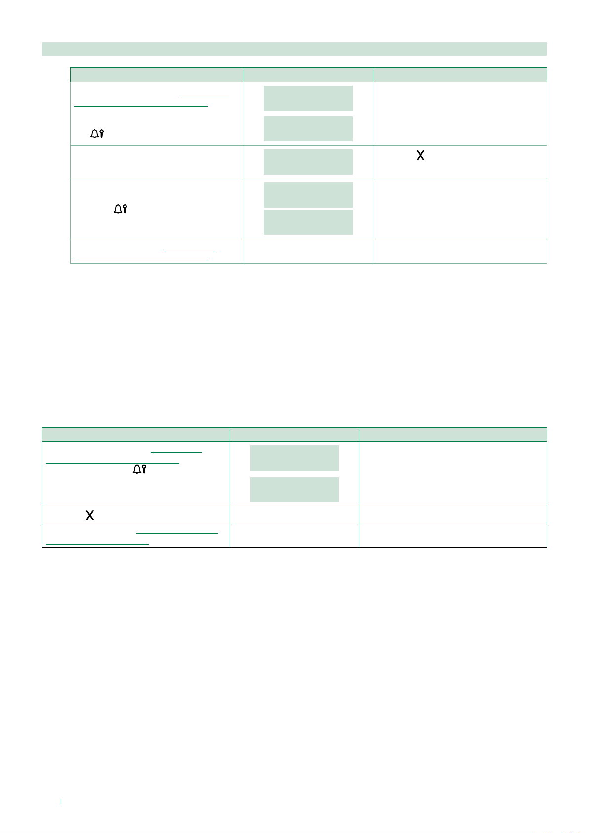
2.2.3. Delete all
PROCEDURE DISPLAY INFO DESCRIPTION
Access configuration (see “Accessing/
exiting the configuration stage”)
Select the menu ACCESS CONTROL /
PASSWORD / DELETE ALL using the
.
key
Press the
Exit configuration (see “Accessing/
exiting the configuration stage”)
key to confirm deletion.
3. Info
This procedure can be used to view:
• the firmware version
• the number of users stored [NO VIP]
• the number of passwords stored [NO VIP]
• the RS485 address [NO VIP]
• the call mode
ACCESS CONTROL
PASSWORD
PASSWORD
DELETE ALL
DELETE
ALL PASSWORD?
PLEASE WAIT
PARAMETER
CHANGED
The menus are scrolled through
automatically every 2 seconds.
Press the key to cancel
the procedure.
PROCEDURE DISPLAY INFO DESCRIPTION
Access configuration (see “Accessing/
exiting the configuration stage”) Select the
menu INFO using the
Press the
Exit configuration (see “Accessing/exiting
the configuration stage”)
key to exit the menu.
key.
MAIN
INFO
Art. 3070B
1.1
The menus are scrolled through
automatically every 2 seconds.
20
Page 21
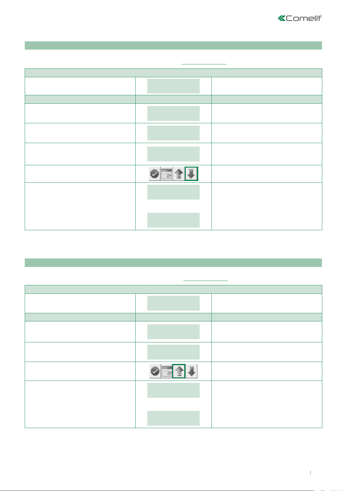
Data management using 1249B [NO VIP]
Entering a list (download)
Software Art.1249B can be used to enter the list with Indirect Code and Code fields for INDIRECT CODE operating mode on
module 3070S. 3070S must be set to indirect code call mode (vedi “1.1.3. Call mode”).
INITIAL CONDITION
Module powered up in standby mode.
PROCEDURE DISPLAY INFO DESCRIPTION
Connect the cable supplied with software Art.
1249B to terminals TX / RX / - (or D / D- if you
have an RS485 line).
Run software Art. 1249B.
Make the list with the Code and Indirect
Code entries in software Art. 1249B, or load
an existing list.
Press the Download button in
software Art. 1249B.
ENTER
USER CODE
ENTER
USER CODE
ENTER
USER CODE
ENTER
USER CODE
DOWNLOADING...
COMPLETED
Or
DOWNLOADING...
ABORTED
On software 1249B with R.I. 003, the
CALL MODE must be set as Indirect Code
without a name entry.
If the download was completed successfully.
If an error occurred during the download.
Reading (upload) of the stored list
Software Art.1249B can be used to read, inside module 3070S, the list with Indirect Code and Code fields for INDIRECT CODE
operating mode. 3070S must be set to indirect code call mode (see “1.1.3. Call mode”).
INITIAL CONDITION
Module powered up in standby mode.
PROCEDURE DISPLAY INFO DESCRIPTION
Connect the cable supplied with software
Art. 1249B to terminals TX / RX / - (or D / Dif you have an RS485 line).
Run software Art. 1249B.
Press the Upload button in
software Art. 1249B.
ENTER
USER CODE
ENTER
USER CODE
ENTER
USER CODE
UPLOAD
COMPLETED
Or
UPLOAD
ABORTED
If the upload was completed successfully.
If an error occurred during the upload.
21
Page 22
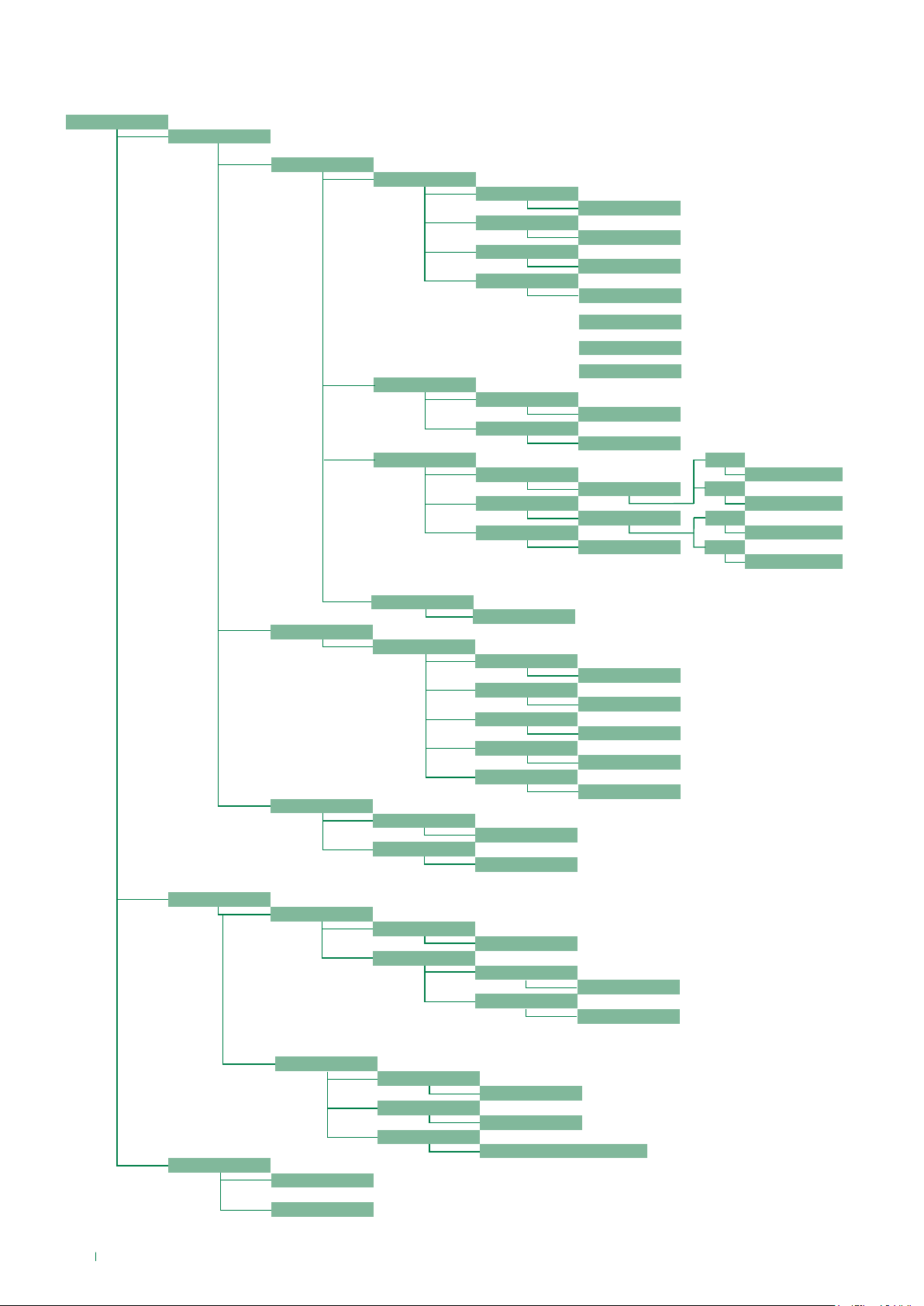
Navigation tree
MAIN
SETTINGS
SYSTEM PARAM.
[NO VIP]
SPEAKER PARAM.
[NO VIP]
[NO VIP]
DOWNLOAD TYPE
CALL MODE
ENTER t AUDIO
ENT. t DOOR LOCK
ENTER t RESET
VIEWING
_ _ _ 0
_ _ _ 1
_ _ _ 0
_ _ _ 1
_ _ _ 2
_ _ 30
_ _ _ 3
_ _ _ 2
AUDIO TIMING
DOOR LOCK TIME
RESET TIME
CALL MODE
RS232
RS485
SIMPLEBUS
SIMPLEBUS TOP
VIP
RANGE SB&SBTOP 10-180
RANGE VIP 30-600
RANGE SB&SBTOP 1-8
RANGE VIP 1-60
RANGE SB&SBTOP 1-10
[NO VIP]
[NO VIP]
[NO VIP]
[NO VIP]
[NO VIP]
_ _ _ 0
STANDARD
_ _ _ 1
INDIRECT CODE
_ _ _ 0
STANDARD
_ _ _ 1
INDIRECT CODE
[NO VIP]
[NO VIP]
[NO VIP]
[NO VIP]
ACCESS CONTROL
LANGUAGE
DEFAULT SETTINGS
SUPERCODICE
ADDRESS RS485
LANGUAGE
_ _ _ 0
_ _ _ 1
CHANGE
DEFAULT SETTINGS
_ 250
_ _ _ 0
_ _ _ 1
_ _ _ 2
_ _ _ _
_ _ 12
YES
NO
VALUE: _ _ _ _ _ _
_ _ _ 0
_ _ _ 1
RANGE SB&SBTOP 0-255
[NO VIP]
ITALIANO
ENGLISH
FRANCAIS
....
DEFAULT
THE SUPERCODE MUST
CONTAIN AT LEAST 4 DIGITS
YES
NO
22
INFO
PASSWORD
ART. 3070B
.....
ENTER
DELETE
DELETE ALL
VALUE: _ _ _ _ _ _
VALUE: _ _ _ _ _ _
THE PASSWORD MUST CONTAIN
AT LEAST 4 DIGITS
ENTER THE EXACT PASSWORD
(THE FIRST TWO DIGITS, IF OMITTED,
WILL BE ENTERED AS ZERO)
DELETE ALL PASSWORD?
Page 23

System performance and layouts
For further information of system performance and to view installation layouts, click on the system type that best meets your
requirements:
• Building Kit audio/video system for the creation of audio-video systems for small apartment blocks.
• SBTOP audio/video system for the creation of audio-video systems for residential complexes.
• SB2 audio system for the creation of audio systems for residential complexes.
• SB1 audio system for the creation of audio systems for residential complexes.
23
Page 24

1ª edizione 07/2018
cod. 2G40002105
CERTIFIED MANAGEMENT SYSTEMS
www.comelitgroup.com
Via Don Arrigoni, 5 - 24020 Rovetta (BG) - Italy
 Loading...