

Page 1

the complete Internet Protocol system:
simple and versatile
Installer manual
www.comelitgroup.com
Page 2

Fonts are (c) Bitstream (see below). DejaVu changes are in public domain.
Glyphs imported from Arev fonts are (c) Tavmjong Bah (see below)
Bitstream Vera Fonts Copyright
-----------------------------Copyright (c) 2003 by Bitstream, Inc. All Rights Reserved. Bitstream Vera is a trademark of Bitstream, Inc.
Permission is hereby granted, free of charge, to any person obtaining a copy of the fonts accompanying this license ("Fonts") and associated documentation les ("Font Software"), to reproduce and distribute the Font Software, including
without limitation the rights to use, copy, merge, publish, distribute, and/or sell copies of the Font Software, and to permit persons to whom the Font Software is furnished to do so, subject to the following conditions:
The above copyright and trademark notices and this permission notice shall be included in all copies of one or more of the Font Software typefaces.
The Font Software may be modied, altered, or added to, and in particular the designs of glyphs or
characters in the Fonts may be modied and additional glyphs or characters may be added to the Fonts, only if the fonts are renamed to names not containing either the words “Bitstream” or the word “Vera”.
This License becomes null and void to the extent applicable to Fonts or Font Software that has been modied and is distributed under the "Bitstream Vera" names.
The Font Software may be sold as part of a larger software package but no copy of one or more of the Font Software typefaces may be sold by itself.
THE FONT SOFTWARE IS PROVIDED "AS IS", WITHOUT WARRANTY OF ANY KIND, EXPRESS OR IMPLIED, INCLUDING BUT NOT LIMITED TO ANY WARRANTIES OF MERCHANTABILITY, FITNESS FOR A PARTICULAR
PURPOSE AND NONINFRINGEMENT OF COPYRIGHT, PATENT, TRADEMARK, OR OTHER RIGHT. IN NO EVENT SHALL BITSTREAM OR THE GNOME FOUNDATION BE LIABLE FOR ANY CLAIM, DAMAGES OR OTHER LIABILITY,
INCLUDING ANY GENERAL, SPECIAL, INDIRECT,
INCIDENTAL, OR CONSEQUENTIAL DAMAGES, WHETHER IN AN ACTION OF CONTRACT, TORT OR
OTHERWISE, ARISING FROM, OUT OF THE USE OR INABILITY TO USE THE FONT SOFTWARE OR
FROM OTHER DEALINGS IN THE FONT SOFTWARE.
Except as contained in this notice, the names of Gnome, the Gnome Foundation, and Bitstream Inc., shall not be used in advertising or otherwise to promote the sale, use or other dealings in this Font Software without prior written authorization
from the Gnome Foundation or Bitstream Inc., respectively. For further information, contact: fonts at gnome dot org.
Arev Fonts Copyright
-----------------------------Copyright (c) 2006 by Tavmjong Bah. All Rights Reserved.
Permission is hereby granted, free of charge, to any person obtaining a copy of the fonts accompanying this license ("Fonts") and associated documentation les (the "Font Software"), to reproduce and distribute the modications to the
Bitstream Vera Font Software, including without limitation the rights to use, copy, merge, publish, distribute, and/or sell copies of the Font Software, and to permit persons to whom the Font Software is furnished to do so, subject to the
following conditions:
is furnished to do so, subject to the following conditions:
The above copyright and trademark notices and this permission notice shall be included in all copies of one or more of the Font Software typefaces.
The Font Software may be modied, altered, or added to, and in particular the designs of glyphs or characters in the Fonts may be modied and additional glyphs or characters may be added to the Fonts, only if the fonts are renamed to
names not containing either the words "Tavmjong Bah" or the word "Arev".
This License becomes null and void to the extent applicable to Fonts or Font Software that has been modied and is distributed under the "Tavmjong Bah Arev" names.
The Font Software may be sold as part of a larger software package but no copy of one or more of the Font Software typefaces may be sold by itself.
THE FONT SOFTWARE IS PROVIDED "AS IS", WITHOUT WARRANTY OF ANY KIND, EXPRESS OR IMPLIED, INCLUDING BUT NOT LIMITED TO ANY WARRANTIES OF MERCHANTABILITY, FITNESS FOR A PARTICULAR
PURPOSE AND NONINFRINGEMENT OF COPYRIGHT, PATENT, TRADEMARK, OR OTHER RIGHT. IN NO EVENT SHALL TAVMJONG BAH BE LIABLE FOR ANY CLAIM, DAMAGES OR OTHER LIABILITY, INCLUDING ANY
GENERAL, SPECIAL, INDIRECT, INCIDENTAL, OR CONSEQUENTIAL DAMAGES, WHETHER IN AN ACTION OF CONTRACT, TORT OR OTHERWISE, ARISING FROM, OUT OF THE USE OR INABILITY TO USE THE FONT
SOFTWARE OR FROM OTHER DEALINGS IN THE FONT SOFTWARE.
Except as contained in this notice, the name of Tavmjong Bah shall not be used in advertising or otherwise
to promote the sale, use or other dealings in this Font Software without prior written authorization from
Tavmjong Bah. For further information, contact: tavmjong @ free. fr.
Warning
• Install the equipment by carefully following the instructions given by the manufacturer and in compliance with the standards in force. In mains-powered devices, do not tamper with the
internal elements offering protection against short circuits and overcurrents.
• All the equipment must only be used for the purpose it was designed for. Comelit Group S.p.A. declines any responsibility for improper use of the apparatus, for any alterations
made by others for any reason or for the use of non-original accessories or materials.
• All the products comply with the requirements of the 2014/30/UE, 2014/35/UE directives, as certied by the CE mark they carry.
• Do not route the riser wires in proximity to power supply cables (230/400V).
• Installation, mounting and assistance procedures for electrical devices must only be performed by specialised electricians.
• The electrical system of the building must be tted with an (easily accessible) omnipolar mains switch with a contact opening of at least 3 mm, which is capable of cutting off the power
supply for mains-powered devices.
• Cut off the power supply before carrying out any maintenance work.
• Place the protection back over the terminals and close the inspection door after every procedure.
• The device conforms to standard EN60950-1 relating to the safety of information technology equipment.
• Do not press and hold the audio hook while the handset is lifted.
TABLE OF CONTENTS
Chapter 1: Introduction to the VIP system ..............................................................................................................................5
What is the VIP system? ...............................................................................................................................................................................5
Main features .................................................................................................................................................................................................5
General structure of a VIP system ...............................................................................................................................................................5
Chapter 2: Description of products and accessories ............................................................................................................ 6
Software .........................................................................................................................................................................................................6
VIP Manager Art. 1449 VIP system conguration software ......................................................................................................................6
Power supply units and system connection accessories .........................................................................................................................6
VIP system riser power supply unit 120 W Art. 1441A ..............................................................................................................................6
VIP system riser power supply unit 100 W Art. 1441 ................................................................................................................................6
Power supply unit Art. 1395 / Art. 1595 for external units .........................................................................................................................7
VIP system POE power supply unit for monitor Art. 1451 ........................................................................................................................7
Switch Art. 1440 ........................................................................................................................................................................................7
VIP system riser signal repeater module Art. 1447 ...................................................................................................................................8
VIP system device barcode reader Art. 1450 ...........................................................................................................................................8
Internal units ..................................................................................................................................................................................................9
Planux backplate Art. 6231 and Planux monitor Art. 6202 ........................................................................................................................9
7Stelle monitor Art. 6501 ..........................................................................................................................................................................10
Smart monitor Art. 6304 ............................................................................................................................................................................10
Easycom door-entry phone Art. 6203 .......................................................................................................................................................11
VIP switchboard Art. 1952 ........................................................................................................................................................................11
Powercom series external units ..................................................................................................................................................................12
Powercom module Art. 3331/0 - 1 - 2 for audio/video units ......................................................................................................................12
Powercom series colour audio/video unit for VIP system Art. 4662C .......................................................................................................12
Powercom call button module Art. 3337/3 - 4 - 6 ......................................................................................................................................12
Powercom series backlit indication module Art. 3327 ...............................................................................................................................13
Powercom series digital call module for VIP system Art. 3370 .................................................................................................................13
IKall series external units .............................................................................................................................................................................14
IKall module Art. 33400 - 33401 - 33402 for audio units ...........................................................................................................................14
2
Page 3

IKall module Art. 33410 - 33411 - 33412 for audio/video units ................................................................................................................. 14
IKall series audio unit for VIP system Art. 1682 ........................................................................................................................................14
IKall series colour audio/video unit for VIP system Art. 4682C .................................................................................................................15
IKall call button module Art. 33433 - 33434 - 33436 .................................................................................................................................15
IKall series digital call module for VIP system Art. 3360A .........................................................................................................................15
Vandalcom series external units .................................................................................................................................................................16
Vandalcom series digital call module for VIP system Art. 3270, for Powercom external unit Art. 4662C .................................................16
Vandalcom series digital call module for VIP system Art. 3070B, for Powercom external units Art. 4662C and IKall external units Art. 4682C .....16
Vandalcom series digital call module for VIP system Art. 3272, for Powercom external unit Art. 4662C .................................................17
Vandalcom series digital call module for VIP system Art. 3072B, for Powercom external units Art. 4662C and IKall external units Art. 4682C .....17
Module Art. 3268I/0 -1 - 2 designed for a/v units, iKall series ...................................................................................................................18
Module Art. 3269/0 - 1 - 2 designed for a/v units, Powercom series ........................................................................................................18
Module Art. 3262I/0 -1 - 2 designed for audio units, IKall series ..............................................................................................................18
Vandalcom series 4-button module Art. 3064/C for VIP system ............................................................................................................... 18
VIP system accessories ...............................................................................................................................................................................19
Remote camera module Art. 1445 ............................................................................................................................................................19
VIP system actuator relay module Art. 1443 .............................................................................................................................................20
PAL / NTSC video output module Art. 1446 ..............................................................................................................................................21
Expansion module Art. SK9071 ................................................................................................................................................................21
Chapter 3: System preparation and specications ................................................................................................................ 22
Connection distances ...................................................................................................................................................................................22
Connection distances from power supply unit Art. 1395 / Art. 1595 to external unit .................................................................................22
Connection distances between external unit and Switch Art. 1440 ..........................................................................................................22
Connection distances between 2 Switches Art. 1440 ...............................................................................................................................22
Connection distances from Switch Art. 1440 / Repeater Art. 1447 to door-entry phones / door entry monitors .......................................23
Connection distances from Switch Art. 1440 / Repeater Art. 1447 to switchboard Art. 1952 ...................................................................23
Expanding a system using repeater Art. 1447 ..........................................................................................................................................23
Guide to tting a UTP / STP RJ45 Direct network cable ............................................................................................................................24
Chapter 4: Mounting external units and internal units .......................................................................................................... 27
Mounting Powercom series external units .................................................................................................................................................28
Mounting external unit Art. 4662C and additional buttons Art. 3337/3 - 4 - 6 ...........................................................................................28
Mounting actuator module Art. 3327 .........................................................................................................................................................29
Mounting digital directory Art. 3370 ..........................................................................................................................................................29
Mounting IKall series external units ............................................................................................................................................................30
Mounting external unit Art. 4682C and additional buttons Art. 33433 - 33434 - 33436 ............................................................................30
Mounting digital directory Art. 3360A ........................................................................................................................................................31
Mounting Vandalcom series external units ................................................................................................................................................32
Connecting audio-video unit Art. 4662C for use with buttons on Vandalcom external unit Art. 3269/1 - 2 ...............................................32
Connecting audio unit 1682 or audio-video unit Art. 4682C for use with buttons on Vandalcom external unit Art. 3262I/1 - 2 and Art. 3268I/1 - 2 ....33
Mounting audio-video unit Art. 4662C or 4682C for use with additional buttons Art. 3064/C ...................................................................34
Mounting digital directories Art. 3270 - 3272 with Powercom external unit Art. 4662C ............................................................................35
Mounting digital directories Art. 3070B - 3072B with IKall external unit Art. 4682C..................................................................................36
Mounting internal units ................................................................................................................................................................................37
Mounting Planux monitor Art. 6202 with ush-mounted box Art. 6117 .....................................................................................................37
Mounting Planux monitor Art. 6202 with wall bracket Art. 6120 ................................................................................................................38
Mounting Sette Stelle monitor Art. 6501 ...................................................................................................................................................39
Mounting 7Stelle monitor Art. 6501 with ush-mounted box Art. 6517 .....................................................................................................40
Mounting Easycom monitor Art. 6203 .......................................................................................................................................................41
Mounting Smart monitor Art. 6304 with wall bracket Art. 6320 .................................................................................................................42
Mounting Smart monitor Art. 6304 with ush-mounted box Art. 6117 .......................................................................................................43
Chapter 5: Installation programming ......................................................................................................................................44
Mac Address ..................................................................................................................................................................................................44
VIP code .........................................................................................................................................................................................................44
Reset procedure for external unit Art. 4662C and 4682C ..........................................................................................................................44
Manually programming buttons on external unit Art. 4662C ....................................................................................................................46
Manually programming buttons on external unit Art. 4682C ....................................................................................................................47
Assigning module index to additional button products Art. 3337/3 - 4 - 6 .............................................................................................48
Assigning module index to additional button products Art. 33433 - 33434 - 33436 ...............................................................................49
Programming internal units .........................................................................................................................................................................50
Planux monitor Art. 6202 and Smart monitor Art. 6304 (only with optional buttons Art. 6332) .................................................................50
Accessing the installer menu ..............................................................................................................................................................50
Setting the menu language ................................................................................................................................................................50
Programming the VIP code for main Planux monitors .......................................................................................................................51
Programming the VIP code for secondary Planux monitors ...............................................................................................................51
Conguring 1 - 2 or Self-ignition buttons ............................................................................................................................................52
Conguring the key button .................................................................................................................................................................53
Conguring the Privacy / Doctor button ..............................................................................................................................................54
Conguring the intercom directory .....................................................................................................................................................54
Conguring the self-ignition directory .................................................................................................................................................55
Conguring the Actuator Directory .....................................................................................................................................................56
Setting the Door Open function ..........................................................................................................................................................57
Setting the Alarm function ..................................................................................................................................................................58
Setting the ringtone repetition ............................................................................................................................................................58
Setting call times ................................................................................................................................................................................59
Setting automatic answer ...................................................................................................................................................................59
Video memory records always ...........................................................................................................................................................60
Activate output ....................................................................................................................................................................................60
Call divert ...........................................................................................................................................................................................61
Reset conguration ............................................................................................................................................................................61
3
Page 4

7Stelle monitor Art. 6501 ..........................................................................................................................................................................62
Accessing the installer menu ..............................................................................................................................................................62
Conguring buttons ............................................................................................................................................................................62
Conguring functions ..........................................................................................................................................................................62
Intercom function .........................................................................................................................................................................62
Self-ignition function .....................................................................................................................................................................62
Alarm function ..............................................................................................................................................................................63
Lock-release function ...................................................................................................................................................................63
Actuator function ..........................................................................................................................................................................63
Activate output function ................................................................................................................................................................63
Conguring the monitor ......................................................................................................................................................................64
VIP address .................................................................................................................................................................................64
About ............................................................................................................................................................................................64
Reset conguration ......................................................................................................................................................................64
Special Settings ..................................................................................................................................................................................64
Actuator Directory ........................................................................................................................................................................64
Camera Directory .........................................................................................................................................................................65
Intercom Directory ........................................................................................................................................................................65
Set ringtone repetition ..................................................................................................................................................................65
Set call times ................................................................................................................................................................................65
Call divert .....................................................................................................................................................................................66
Alarms ..........................................................................................................................................................................................66
Door open ....................................................................................................................................................................................66
Activate output .............................................................................................................................................................................66
Automatic answer ........................................................................................................................................................................66
Video memory records always .....................................................................................................................................................66
Porter switchboard Art. 1952 ....................................................................................................................................................................67
Accessing the installer menu ..............................................................................................................................................................67
Setting the VIP Address .....................................................................................................................................................................67
Setting the associated camera ...........................................................................................................................................................67
Setting the associated video output ...................................................................................................................................................67
Programming the self-ignition key ......................................................................................................................................................68
Programming the lock-release key .....................................................................................................................................................68
Activating / deactivating the OFF key .......................................................................................................................................................68
Setting the call times .................................................................................................................................................................................69
Setting call divert ......................................................................................................................................................................................69
Setting activations on call .........................................................................................................................................................................69
Chapter 6: Wiring diagrams .....................................................................................................................................................70
Connecting Powercom call button module Art. 3337/3-4-6 .......................................................................................................................70
Connecting Powercom series digital call module Art. 3370 .....................................................................................................................71
Connecting backlit module with actuator relay Art. 3327 .........................................................................................................................72
Connecting IKall call button module Art. 3343/3-4-6 .................................................................................................................................73
Connecting IKall series audio unit for VIP system Art. 1682 ....................................................................................................................74
Connecting IKall series digital call module Art. 3360A .............................................................................................................................75
Connecting Vandalcom series digital call modules Art. 3070B and Art. 3072B with IKall series external units Art. 4682C or 1682 .76
Connecting Vandalcom series digital call modules Art. 3270 and Art. 3272 with Powercom series external unit Art. 4662C ...........77
Connecting Art. 3064/C with audio-video unit 4682C or audio unit Art. 1682 ........................................................................................78
Connecting remote camera module Art. 1445 ............................................................................................................................................79
Connecting PAL / NTSC module Art. 1446 ..................................................................................................................................................80
Connecting repeater module Art. 1447 .......................................................................................................................................................81
Connecting IO module Art. 1443 and expansion device Art. SK9071 ......................................................................................................82
Request to exit (RTE) button input variant .................................................................................................................................................83
Planux VIP output and input variant ...........................................................................................................................................................83
7Stelle output and input variant ..................................................................................................................................................................84
Smart output and input variant ....................................................................................................................................................................84
Easycom output and input variant ..............................................................................................................................................................85
Connection of Vandalcom nameplate lighting lamp with audio unit Art. 1682 or audio-video unit Art. 4682C (Ikall) .........................85
Connecting Planux VIP additional ringtone variant ...................................................................................................................................86
Connecting 7Stelle additional ringtone variant ..........................................................................................................................................86
Connecting Smart additional ringtone variant ...........................................................................................................................................86
Connecting Easycom additional ringtone variant .....................................................................................................................................86
4
Page 5
Chapter 1: Introduction to the VIP system
What is the VIP system?
The VIP system is the new IP video entry phone system combining powerful performance with ease of installation. The VIP network, based on a
connection via Ethernet cable, connects an innite number of users in simultaneous conversations and with no distance restrictions. It integrates a
video entry phone system, burglar alarm, video surveillance, home automation and access control functions into a single system.
The VIP System can be used to create either a dedicated, proprietary network or integrated into an existing LAN, creating a video entry phone system
that runs in parallel with other existing systems.
Main features
The VIP System delivers optimal performance across an intelligible infrastructure, untangling the communication, control, security, automation and
monitoring apparatus needed for access and building control.
• Multiple simultaneous audio-video conversations
• An unlimited number of users and devices can be plugged into the network
• No limits on the number of connected entrance panels, internal units, switchboards and cameras
• All network devices are connected to the network via RJ45 plug
• Simultaneous communication capabilities between all network users
• Memovideo function installed as standard on all monitors
• Interface management for lifts and additional oors
• Integrated access control and video surveillance options
• Alarms or panic messages can be sent to porter switchboards
• Audio and text messages between users and switchboards
• "Follow me" and data transfer to external applications (PC or telephone)
• Remote home automation management
General structure of a VIP system
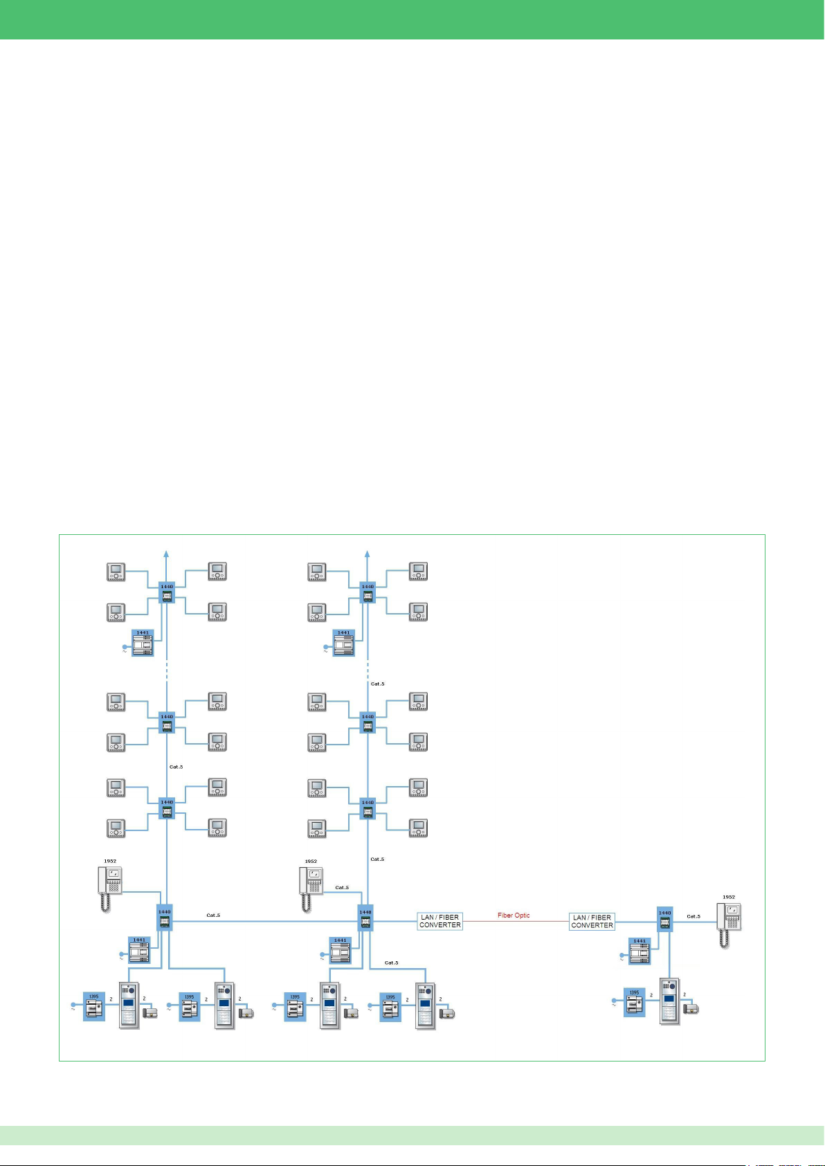
Below is a synoptic diagram providing a general illustration as to how a VIP system can be laid out.
The optimal freedom offered by the VIP system means that networks can be created using cascade or branch connections, with no restrictions.
5
Page 6
Chapter 2: Description of products and accessories
+V
+V
Software
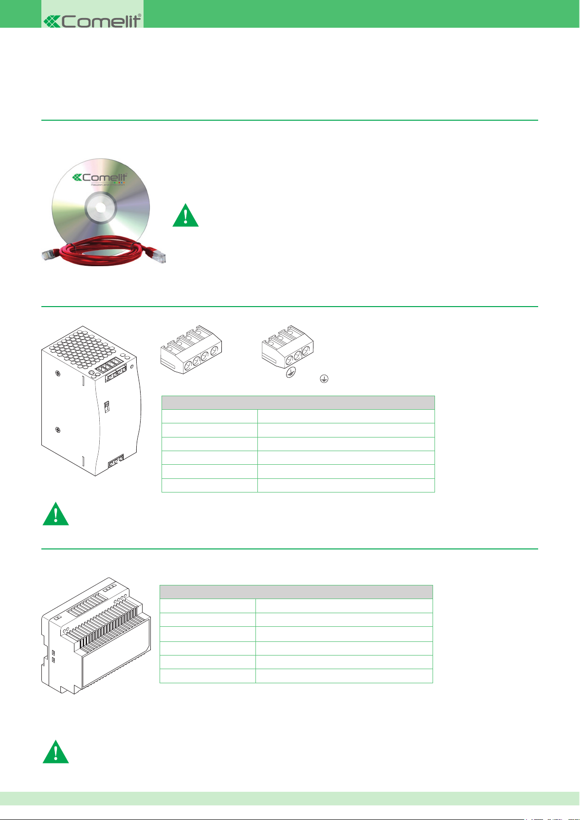
VIP Manager Art. 1449 VIP system conguration software
CD-ROM software for PC installation, for the programming and conguration of all wired devices in the system. Also allows button programming and
management of names in external unit directories. Includes a special cable for connection between switch 1440 and PC.
When connecting a PC to a VIP system, the special cable supplied with software Art. 1449
must be used
Power supply units and system connection accessories
VIP system riser power supply unit 120 W Art. 1441A
Power supply unit Art. 1441A, to power all accessories connected to the riser (not including external units).
Terminal blocks for connection
-V
-V
Technical characteristics
Input voltage
Output voltage 48 V DC (2.5 A)
Power 120 W
Frequency 50/60 Hz
Temperature thresholds -30°C / +55°C
Dimensions 4 DIN modules / H: 12.5 cm W: 6.5 cm D: 10.7 cm
• Install the equipment by carefully following the instructions given by the manufacturer and in compliance with the standards in force. Do not tamper with the internal elements
offering protection against short circuits and overcurrents.
• The electrical system of the building must be tted with an (easily accessible) omnipolar mains switch with a contact opening of at least 3 mm, which is capable of cutting off
the power supply of the device.
100 - 240 V~ (3 A)
+V +V -V -V: Riser power supply terminals.
L
N
L N: Alternating 230 V~ network terminals.
: Earth. connection terminal.
VIP system riser power supply unit 100 W Art. 1441
Power supply unit Art. 1441, to power all accessories connected to the riser (not including external units).
Technical characteristics
Input voltage
Output voltage 56 V DC (1.8 A)
Power 100 W
Frequency 50/60 Hz
Temperature thresholds -30 +55
Dimensions 6 DIN modules / H: 9.3 cm W: 9.9 cm D: 5.3 cm
100 - 240 V~ (3 A)
Terminal blocks for connection
+V -V: Riser power supply terminals.
L N: Alternating 230 V~ network terminals.
• Install the equipment by carefully following the instructions given by the manufacturer and in compliance with the standards in force. Do not tamper with the internal
elements offering protection against short circuits and overcurrents.
• The electrical system of the building must be tted with an (easily accessible) omnipolar mains switch with a contact opening of at least 3 mm, which is capable of cutting
off the power supply of the device.
6
Page 7
Power supply unit Art. 1395 / Art. 1595 for external units
Technical characteristics
Input voltage
Output voltage
Power
Frequency
Art. 1395 Art. 1595
207 - 257 V~ (3 A) 120-230 V~ (0,8 A)
12 V~ (1,8 A) 33 V ± 3% (0,5 A)
60 W
50/60 Hz
Temperature thresholds -20 / +40°C
Dimensions 4 DIN modules / H: 9 cm W: 7.15 cm D: 6.2 cm
Terminal blocks for connection Art. 1395
230V ~:
Alternating 230 Vac network terminals.
0 12~:
Power supply output terminals.
Terminal blocks for connection Art. 1595
120-230 V ~
+ -:
: Power supply terminals.
Power supply output terminals.
• Install the equipment by carefully following the instructions given by the manufacturer and in compliance with the standards in force. Do not tamper with the internal elements
offering protection against short circuits and overcurrents.
• The electrical system of the building must be tted with an (easily accessible) omnipolar mains switch with a contact opening of at least 3 mm, which is capable of cutting
off the power supply of the device.
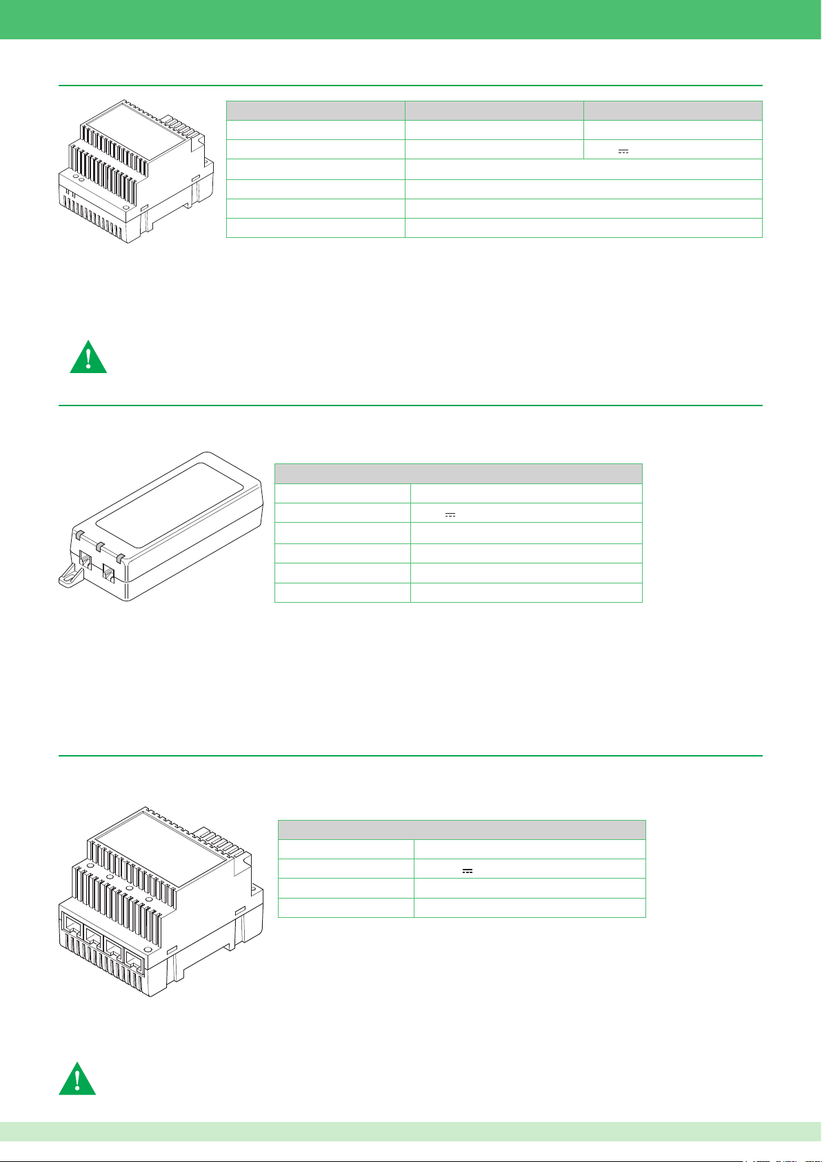
VIP system POE power supply unit for monitor Art. 1451
The power supply unit converts an Ethernet connection into a POE-type connection supplying an internal unit. The power supply unit is necessary if
VIP devices (door entry monitors / door-entry phones) are installed on existing Ethernet networks with non-POE (Power Over Ethernet) connections.
Technical characteristics
Input voltage
Output voltage
100 - 240
56 V (0.35 A)
Power 33.6 W
Frequency 50 - 60 Hz
Temperature thresholds -20 / +50°C
Dimensions H: 3.7 cm W: 6.5 cm D: 16.4 cm
V~
(0.95 A)
Indicator LED
ON: Power supply enabled indication
FAU LT: Error indication
CONNECT: Ethernet cable connected to OUT port indication
Ethernet ports
OUT: for the connection of internal units
IN: for the connection of a non-POE Ethernet network
Switch Art. 1440
The Ethernet Switch module Art. 1440 performs two main functions:
• Directing data VIP system data packages.
• Provide a power supply for the extensions connected to it and to any switch/repeaters connected in cascade.
Technical characteristics
Absorption Min. 0.7 W Max. 2.6 W
Power supply
Temperature thresholds -30 / +55°C
Dimensions 4 DIN modules / H: 6.2 cm W: 7.2 cm D: 9 cm
Ethernet port status indicator LED
Lit steadily: port in standby
Flashing: data passing through the port
Off: port not connected
IN1 IN2 100 Mb riser Ethernet ports. Used for the connection of distributors, such as repeaters, switches, internal units etc.
OUT1 OUT2 OUT3 OUT4: 10 Mb extension Ethernet port. Used for the connection of distributors, such as repeaters, switches, internal units etc.
+ -: External power supply terminals. Connection of power supply unit Art. 1441 or Art. 1441A
36/57 V 3A Max.
For correct operation of the system protecting Art. 1440, the riser must be connected with input on port IN1 and
output on port IN2
7
Page 8
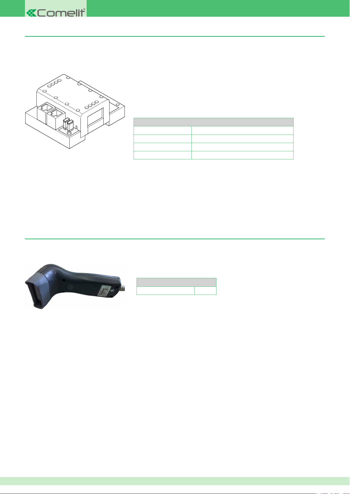
VIP system riser signal repeater module Art. 1447
The repeater module Art. 1447 is used to extend networks, making it possible to connect a VIP device at a greater distance than would be possible
using a single section of point-to-point Ethernet and, if necessary, to connect two risers to each other.
Technical characteristics
Absorption Min. 0.7 W Max. 2.6 W
Power supply 36/57 Vdc 3A Max.
Temperature thresholds -30 / +55°C
Dimensions 4 DIN modules / H: 3.6 cm W: 6.5 cm D: 8.3 cm
1. Ethernet In port
2. Ethernet Out port
3. JP2 Jumper: negative pole separation (GND)
4. JP1 Jumper: positive pole separation (+)
The two Ethernet ports are polarised as an IN input port and an OUT output port. In general, the repeater will receive power from the input port and
supply power to the remote device (door-entry phone, switch, repeater) via the output port. This distinction was made to interrupt power supply
propagation between the In port and the Out port by removing Jumpers JP1 and JP2, in order to separate - for example - the power supplies to two
risers. The device even operates correctly if the output port is switched with the input port. In this case, however, it will no longer be possible to interrupt
power supply propagation.
VIP system device barcode reader Art. 1450
Barcode reader for identifying the unique code of the devices making up the VIP system, for example: door-entry phones, door entry monitors, external
units, actuators, etc...
Technical characteristics
Power supply USB
8
Page 9
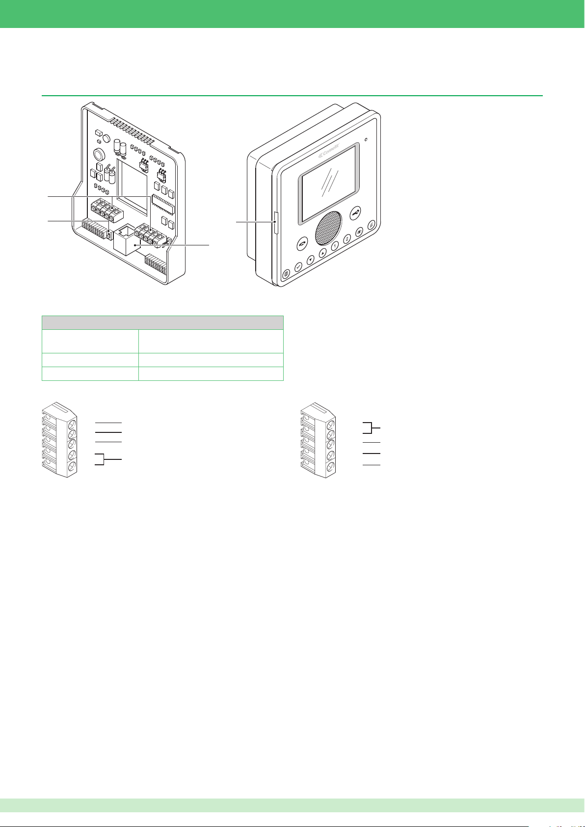
Internal units
1
2
3
4
0V
PA N
CFP
S+
0V
Planux backplate Art. 6231 and Planux monitor Art. 6202
Technical characteristics
Absorption
Power supply 36/57 Vdc 3A Max.
Dimensions H: 6.2 cm W: 7.2 cm D: 9 cm
Min. 0.7 W Max. 2.6 W (value for
complete backplate + monitor product)
1.
Connection terminals
0V
PA N
CFP
0V
S+
2.
VIP - POE selector for tting to the latter if the internal unit is used on a standard - not VIP - PoE network
3.
RJ45 Ethernet connector for connecting the internal unit to the VIP network
4.
SD Card slot
Reference for CFP and PAN terminals
Panic contact terminal
Floor door call contact terminal
Additional ringtone terminals
OPOP+
0V
OUT 1
AL
Optically coupled input terminals
Reference for OUT1 and AL terminals
Output terminal 12 V MAX 100 mA
Alarm contact terminal
We recommend using VIP Manager software Art. 1449 to congure the internal unit (see specic manual). However, the main parameters can also be
congured directly, on the device itself (see page 50).
For wiring details, refer to the diagrams section at the end of this manual.
9
Page 10
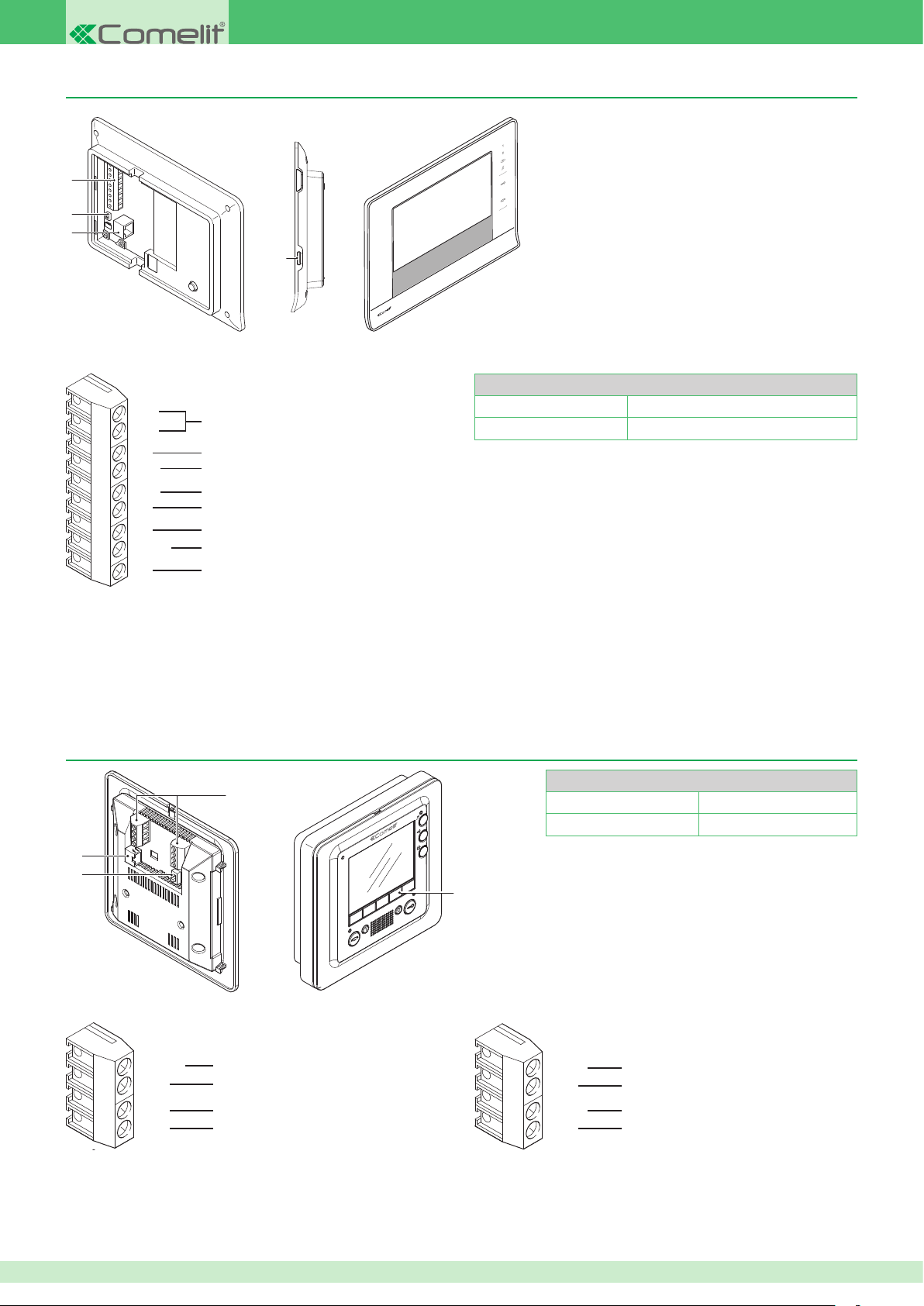
3
1
2
7Stelle monitor Art. 6501
OUT1
0V
S+
IN1
1
2
3
1.
Connection terminals
OP+
OP-
S+
CFP
PAN
0V
AL
OUT1
0V
Optically coupled input terminals
Additional ringtone terminals
Floor door call contact terminal
Panic contact terminal
Reference for CFP, PAN and S+ terminals
Alarm contact terminal
Output terminal 12 V MAX 100 mA
Reference for OUT1 and AL terminals
4
Technical characteristics
Absorption Min. 0.7 W Max. 2.6 W
Power supply 36/57 Vdc 3A Max.
2.
VIP - POE selector for tting to the latter if the internal unit is used on a standard - not VIP - PoE network
3.
RJ45 Ethernet connector for connecting the internal unit to the VIP network
4.
SD Card slot
We recommend using VIP Manager software Art. 1449 to congure the internal unit (see specic manual). However, the main parameters can also be
congured directly, on the device itself (see page 62).
For wiring details, refer to the diagrams section at the end of this manual.
Smart monitor Art. 6304
Technical characteristics
Absorption Min. 0.7 W Max. 2.6 W
Power supply 36/57 Vdc 3A Max.
For wiring details, refer to the diagrams section at the end
of this manual.
3
2
1.
Connection terminals
1
4
OUT1
2.
3.
4.
IN1
S+
0V
VIP - POE selector for tting to the latter if the internal unit is used on a standard - not VIP - PoE network
RJ45 Ethernet connector for connecting the internal unit to the VIP network
Optional buttons Art. 6332
Output terminal 12 V MAX 100 mA
Input terminal 1
Additional ringtone terminals
Reference for CFP, PAN and S+ terminals
CFP
AL
PAN
0V
Floor door call contact terminal
Alarm contact terminal
Panic contact terminal
Reference for OUT1 and AL terminals
We recommend using VIP Manager software Art. 1449 to congure the internal unit (see specic manual). However, the main parameters can also be
congured directly, on the device itself (see page 50).
10
Page 11
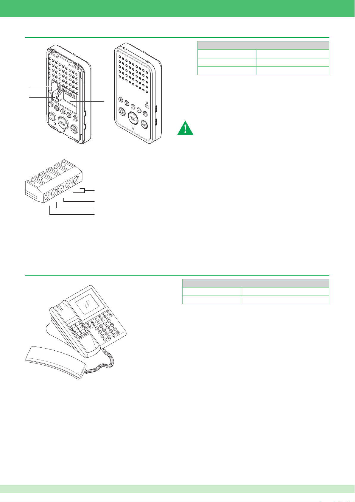
2
3
1
1
GND
Easycom door-entry phone Art. 6203
2
3
1.
Connection terminals
Technical characteristics
Absorption Min. 0.7 W Max. 2.6 W
Power supply 36/57 Vdc 3A Max.
Dimensions H: 16 cm W: 9.1 cm D: 2.7 cm
The Easycom door-entry phone Art. 6203 manages up to
3 slave devices, not 4 as with other internal units.
S+
S-
CFP
AL
Ringtone repetition terminals
Floor door call contact terminal
Alarm contact terminal
Common terminal for alarm contact and oor door call
2.
VIP - POE selector for tting to the latter if the internal unit is used on a standard - not VIP - PoE network
3.
RJ45 Ethernet connector for connecting the internal unit to the VIP network
Use VIP Manager software Art. 1449 to congure the internal unit (see specic manual).
For wiring details, refer to the diagrams section at the end of this manual.
VIP switchboard Art. 1952
Technical characteristics
Absorption Min. 0.7 W Max. 2.6 W
Power supply 36/57 Vdc 3A Max.
We recommend using VIP Manager software Art. 1449 to congure the internal unit (see specic manual). However, the main parameters can also be
congured directly, on the device itself (see page 67).
For wiring details, refer to the diagrams section at the end of this manual.
11
Page 12
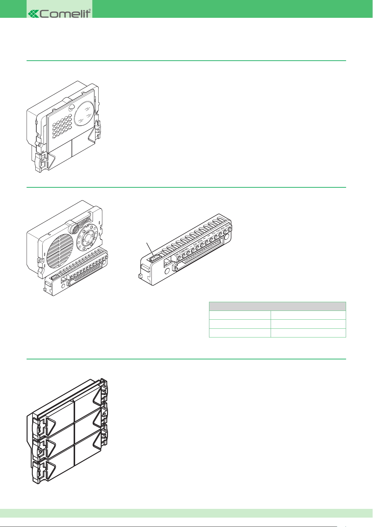
Powercom series external units
Powercom module Art. 3331/0 - 1 - 2 for audio/video units
Module designed for audio/video speaker units. Requires audio/video unit Art. 4662C to complete installation. Versions with 0, 1 and 2 buttons are
available.
Powercom series colour audio/video unit for VIP system Art. 4662C
VIP system audio-video unit with terminal block, complete with spherical lens adjustable colour camera.
1
1.
4-pole cable connector
For wiring details, refer to the diagrams section at the end of this manual.
Powercom call button module Art. 3337/3 - 4 - 6
Additional call button module. Versions with 3, 4 and 6 buttons are available.
NC / NO: Door lock connection terminals
COM: Common terminal
DO: Door Open terminal
RTE / -: Timed relay control terminals
~ ~: Power supply terminals
TX- / TX+: Ethernet transmission line terminals
RX- / RX+: Ethernet reception line terminals
Technical characteristics
Power supply 12 Vac
Temperature thresholds -30 / +55°C
Dimensions H: 10.2 cm W: 5.5 cm D: 3.5 cm
For wiring details, see page 28.
12
Page 13
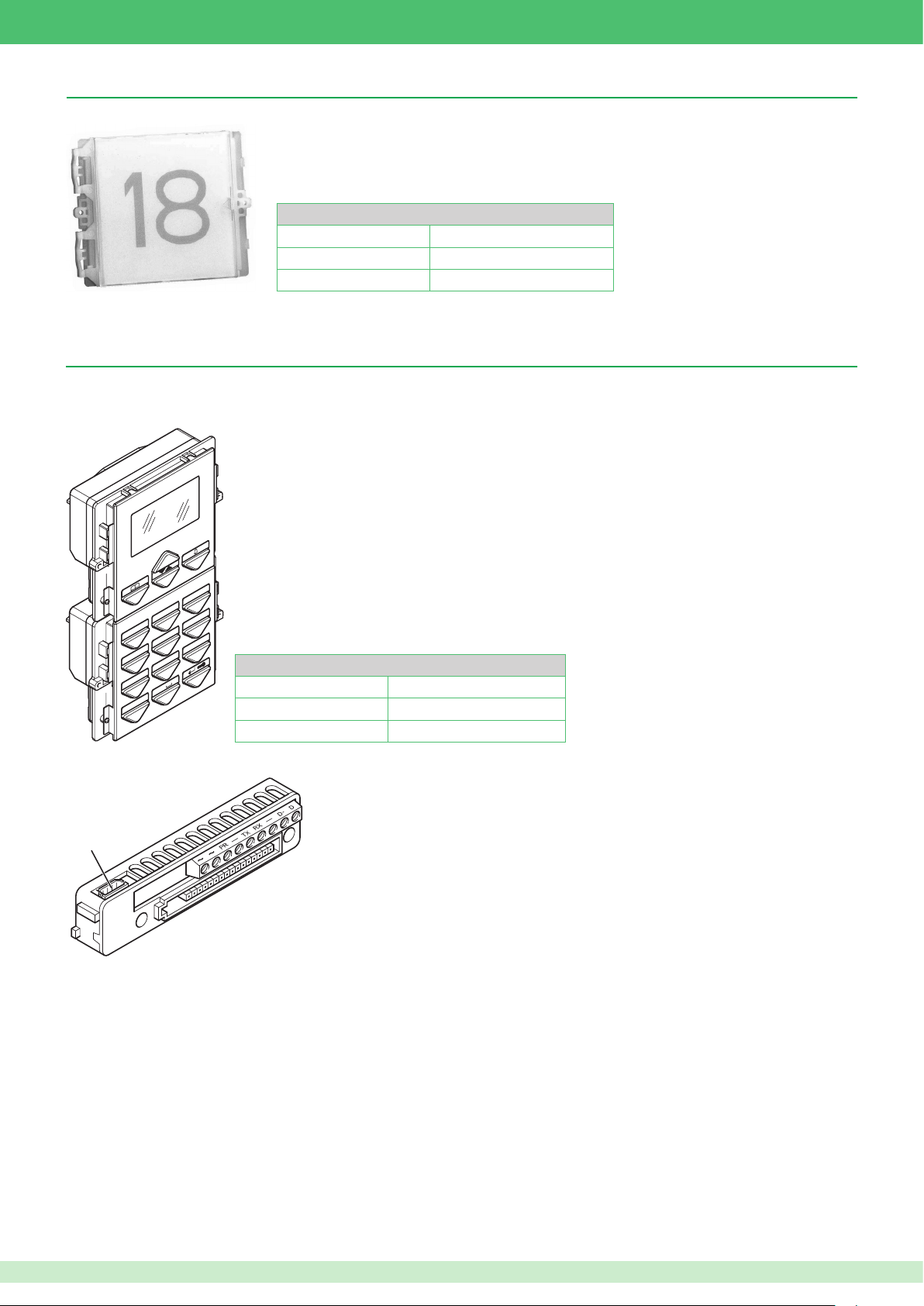
Powercom series backlit indication module Art. 3327
Backlit module with LEDs for various indications and additional 10 A relay.
Technical characteristics
Power supply 12 Vac 3A
Temperature thresholds -30 / +55°C
Dimensions H: 8.9 cm W: 11.2 cm D: 4 cm
For wiring details, see page 29.
Powercom series digital call module for VIP system Art. 3370
Digital call module complete with electronic directory with graphic LCD display. Also functions as a coded electronic key module. Names can be scrolled
using the two search buttons or by entering the initial letter of the required name. Once the right name has been found, press the call button. The user
code can also be entered to make a direct call.
I
G H
3
D E F
2
PQRS
A B C
1
J K L
4
T U V
7
X
6
M N O
5
. , :
9
WXYZ
8
0
Technical characteristics
Power supply 12 Vac
Temperature thresholds -30 / +55°C
Dimensions H: 18 cm W: 11.2 cm D: 4 cm
1
~ ~: Power supply terminals
PR -: Programming terminals
TX RX: RS232 line terminals (not used)
-: RS232 line negative terminal (not used)
D- D: RS485 data line
1.
4-pole cable connector
For wiring details, refer to the diagrams section at the end of this manual.
N.B. Up to this point, the functions linked to the RS485 line have not been implemented.
13
Page 14
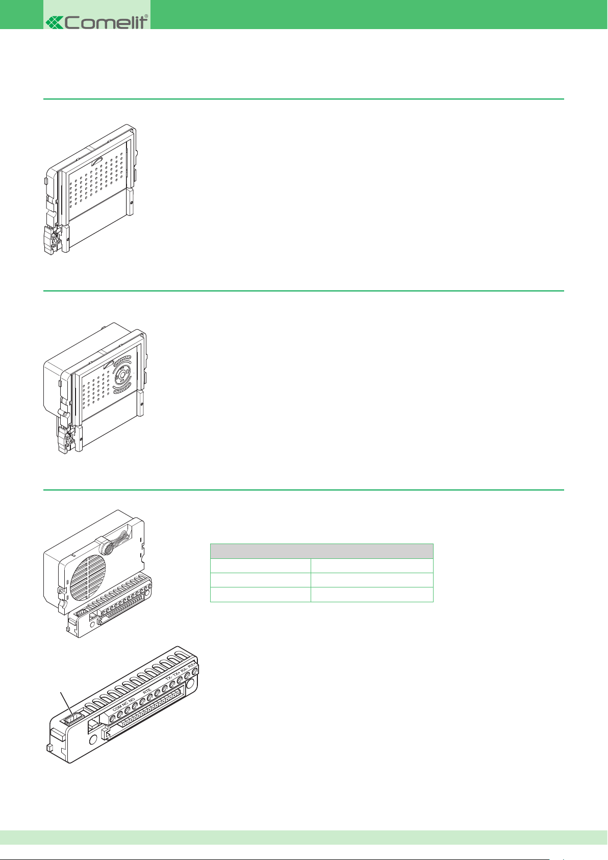
IKall series external units
IKall module Art. 33400 - 33401 - 33402 for audio units
Module with facility for audio porter units. Requires audio unit Art. 1682 to complete installation. Versions with 0, 1 and 2 buttons are available.
IKall module Art. 33410 - 33411 - 33412 for audio/video units
Module preset for audio/video speaker units. Requires audio/video unit Art. 4682C to complete installation. Versions with 0, 1 and 2 buttons are
available.
IKall series audio unit for VIP system Art. 1682
Door-entry phone porter unit for VIP system, complete with terminal block.
Technical characteristics
Power supply 33 Vdc
Temperature thresholds -30 / +55°C
Dimensions H: 10.2 cm W: 5.5 cm D: 3.5 cm
+V
1
SE
1.
8-pole cable connector
For wiring details, refer to the diagrams section at the end of this manual.
-V
GND
SE: Door lock connection terminals
NC / NO: Normally closed and normally open output terminals
COM: Common terminal
RTE / GND: Timed relay control terminals
-V +V: Power supply terminals
TX- / TX+: Ethernet transmission line terminals
RX- / RX+: Ethernet reception line terminals
14
Page 15
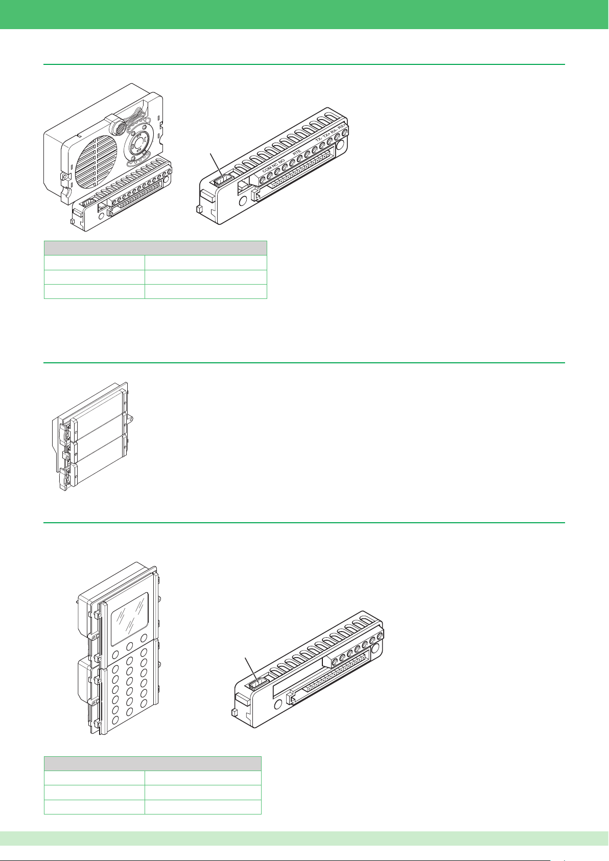
IKall series colour audio/video unit for VIP system Art. 4682C
VIP system audio-video unit with terminal block, complete with mini lens adjustable colour camera.
+V
1
SE
-V
GND
1.
8-pole cable connector
Technical characteristics
Power supply 33 Vdc
Temperature thresholds -30 / +55°C
Dimensions H: 10.2 cm W: 5.5 cm D: 3.5 cm
SE: Door lock connection terminals
NC / NO: Normally closed and normally open output terminals
COM: Common terminal
RTE / GND: Timed relay control terminals
-V +V: Power supply terminals
TX- / TX+: Ethernet transmission line terminals
RX- / RX+: Ethernet reception line terminals
For wiring details, refer to the diagrams section at the end of this manual.
IKall call button module Art. 33433 - 33434 - 33436
Additional call button module. Versions with 3, 4 and 6 buttons are available.
For wiring details, see page 30.
IKall series digital call module for VIP system Art. 3360A
Digital call module complete with electronic directory with graphic LCD display. Also functions as a coded electronic key module. Names can be scrolled
using the two search buttons or by entering the initial letter of the required name. Once the right name has been found, press the call button. The user
code can also be entered to make a direct call.
1
Technical characteristics
Power supply 24 Vac - 33 Vdc
Temperature thresholds -30 / +55°C
Dimensions H: 18 cm W: 11.2 cm D: 4 cm
24Vac
24Vac
S
D+
485
D-
485
GND
PRG
1.
8-pole cable connector
24 Vac: Local power supply terminals (for use when
a dedicated power supply unit needs to be
connected for module Art. 3360A)
PRG GND: Programming terminals
485 D- 485D+: RS485 data line
For wiring details, refer to the diagrams section at the end of this manual.
15
Page 16
-
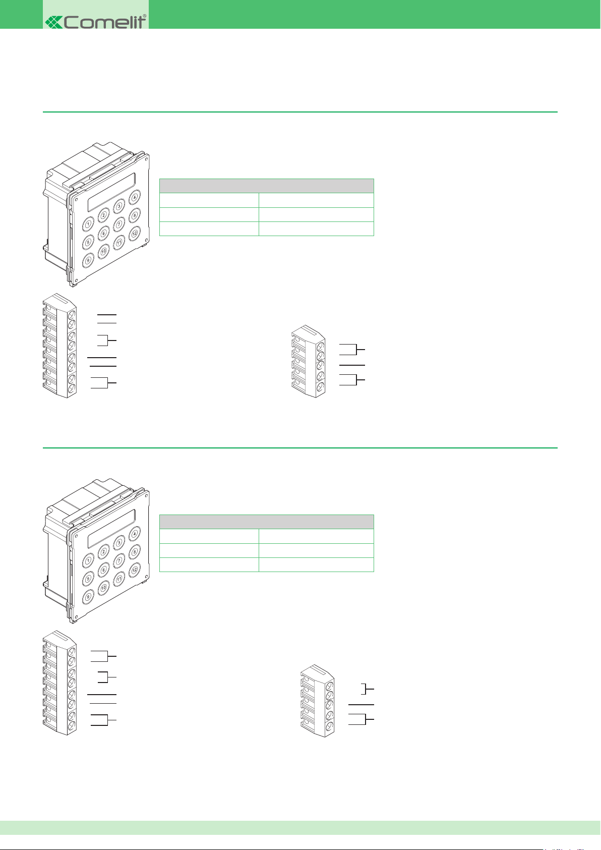
Vandalcom series external units
PR
-
S
12
~
~
⁕
~
12
~
-
-
PR
-
S
12
~
12
~
-
V+
V-
Vandalcom series digital call module for VIP system Art. 3270, for Powercom external unit
Art. 4662C
Digital call module complete with electronic directory with graphic LCD display. Also functions as a coded electronic key module. The user code can
be entered directly to make a call.
Technical characteristics
Power supply 12 Vac
Temperature thresholds -30 / +55°C
Dimensions H: 18 cm W: 11.2 cm D: 4 cm
For wiring details, refer to the diagrams section at the end of this manual.
~
~
12
12
PR
⁕
~
~
S
-
NOT USED
NOT USED
Powercom power supply terminals
Data connection terminal for the external unit
Common terminal
Programming terminals
D
D-
-
RX
TX
NOT USED
NOT USED
NOT USED
Vandalcom series digital call module for VIP system Art. 3070B, for Powercom external units
Art. 4662C and IKall external units Art. 4682C
Digital call module complete with electronic directory with graphic LCD display. Also functions as a coded electronic key module. The user code can
be entered directly to make a call.
Technical characteristics
Power supply 12 Vac - 33 Vdc
Temperature thresholds -30 / +55°C
Dimensions H: 18 cm W: 11.2 cm D: 4 cm
For wiring details, refer to the diagrams section at the end of this manual.
V+
V-
12
~
12
~
S
-
PR
16
Ikall power supply terminals
Powercom power supply terminals
Data connection terminal for the external unit
Common terminal
Programming terminals
D+ 485
D- 485
-
RX
TX
NOT USED
NOT USED
NOT USED
Page 17
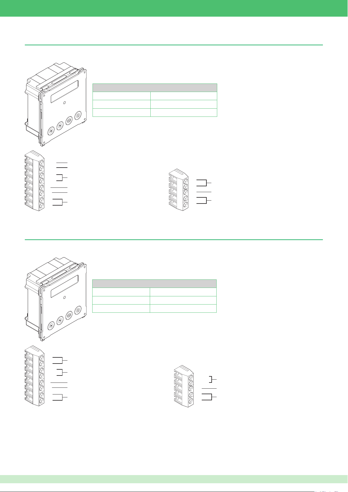
Vandalcom series digital call module for VIP system Art. 3272, for Powercom external unit
-
PR
-
S
12
~
~
⁕
~
12
~
-
-
PR
-
S
12
~
12
~
-
V+
V-
Art. 4662C
Digital call module complete with electronic directory with graphic LCD display. Name scrolling is carried out using two search buttons. Once the right
name has been found, press the call button.
Technical characteristics
Power supply 12 Vac
Temperature thresholds -30 / +55°C
Dimensions H: 18 cm W: 11.2 cm D: 4 cm
For wiring details, refer to the diagrams section at the end of this manual.
~
~
12
12
PR
⁕
~
~
S
-
NOT USED
NOT USED
Powercom power supply terminals
Data connection terminal for the external unit
Common terminal
Programming terminals.
D
D-
-
RX
TX
NOT USED
NOT USED
NOT USED
Vandalcom series digital call module for VIP system Art. 3072B, for Powercom external units
Art. 4662C and IKall external units Art. 4682C
Digital call module complete with electronic directory with graphic LCD display. Name scrolling is carried out using two search buttons. Once the right
name has been found, press the call button.
Technical characteristics
Power supply 12 Vac - 33 Vdc
Temperature thresholds -30 / +55°C
Dimensions H: 18 cm W: 11.2 cm D: 4 cm
For wiring details, refer to the diagrams section at the end of this manual.
V+
V-
12
~
12
~
S
-
PR
Ikall power supply terminals
Powercom power supply terminals
Data connection terminal for the external unit
Common terminal
Programming terminals
D+ 485
D- 485
-
RX
TX
NOT USED
NOT USED
NOT USED
17
Page 18
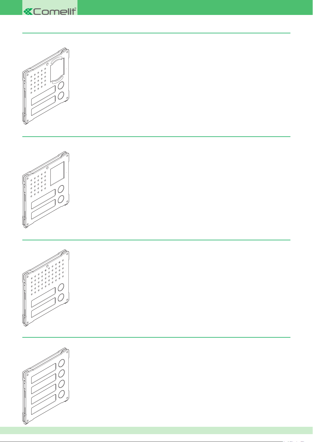
Module Art. 3268I/0 -1 - 2 designed for a/v units, iKall series
Module designed for audio/video porter units. Requires audio/video unit Art. 4682C to complete installation. Versions with 0, 1 and 2 buttons are
available.
For wiring details, see page 33.
Module Art. 3269/0 - 1 - 2 designed for a/v units, Powercom series
Module preset for audio/video speaker units. Requires audio/video unit Art. 4662C to complete installation. Versions with 0, 1 and 2 buttons are
available.
For wiring details, see page 32.
Module Art. 3262I/0 -1 - 2 designed for audio units, IKall series
Module with facility for audio porter units. Requires audio unit Art. 1682 to complete installation. Versions with 0, 1 and 2 buttons are available.
For wiring details, see page 33.
Vandalcom series 4-button module Art. 3064/C for VIP system
Module with 4 additional call buttons.
18
For wiring details, see page 34.
Page 19
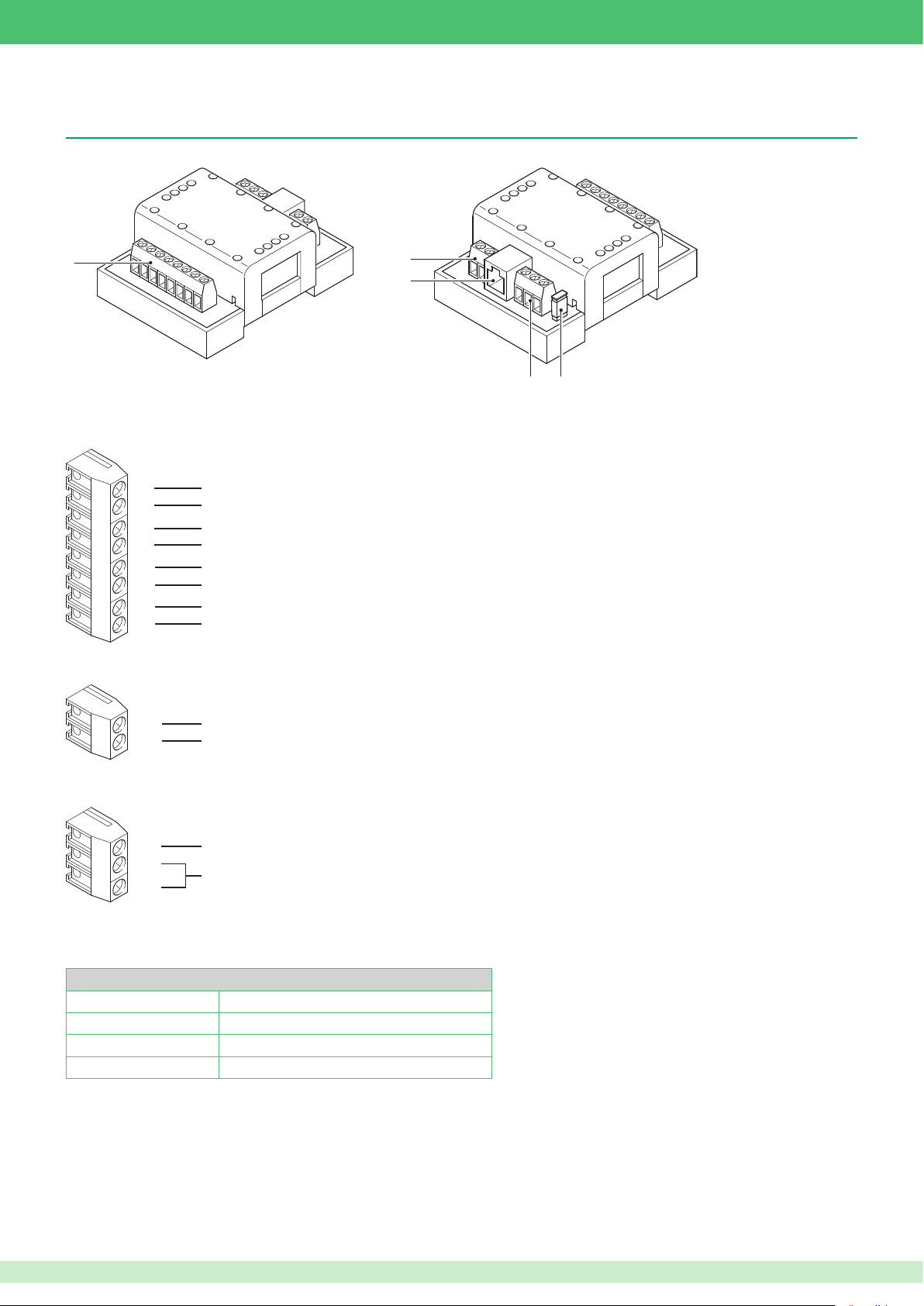
1
2
3
54
54
VIP system accessories
Remote camera module Art. 1445
Remote camera module Art. 1445 transmits the video signals received from 4 cameras.
2
3
1. Video signal from cameras input terminals
V1
SH
V2
SH
V3
SH
V4
SH
2. Secondary power supply terminals.
To be used if the POE network power supply is insufcient
AUX
GND
3. Network connection Ethernet port.
4. RS485 line terminals.
GND
D-
D+
5. RS485 line closure jumper
Input terminal for composite video signal from camera 1
Camera 1 shield terminal
Input terminal for composite video signal from camera 2
Camera 2 shield terminal
Input terminal for composite video signal from camera 3
Camera 3 shield terminal
Input terminal for composite video signal from camera 4
Camera 4 shield terminal
12 - 24 V DC power supply terminal
Earth terminal
Earth terminal
RS485 data line
N.B. Up to this point, the functions linked to the RS485 line have not been implemented.
Technical characteristics
Absorption Min. 0.7 W Max. 2.6 W
Power supply 36/57 Vdc 3A Max.
Temperature thresholds -30 / +55°C
Dimensions 4 DIN modules / H: 3.6 cm W: 6.5 cm D: 8.3 cm
For wiring details, refer to the diagrams section at the end of this manual.
19
Page 20
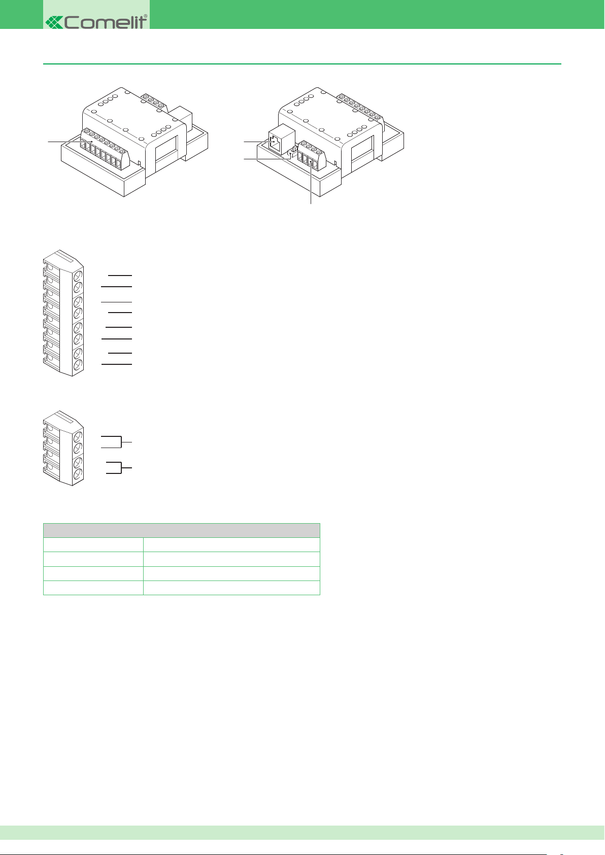
1
3
2
4
2
VIP system actuator relay module Art. 1443
IO module Art. 1443 can be used to control 1 relay on board the device itself or on board any expansion units Art. SK9071 connected to it.
3
4
1. Terminal block for on-board relay inputs and output
GND
IN1
IN2
GND
OC1
NC
COM
NO
Earth terminal
Input terminal 1
Input terminal 2
Earth terminal
Open collector output terminal
On-board relay normally closed terminals
Common terminal for NC / NO
On-board relay normally open terminals
2. Terminals for connection of expansion module Art. SK9071
D+
D-
GND
12V
Art. Sk9071 connection terminals
Art. Sk9071 12 VDC power supply terminals
3. Network connection Ethernet port
4. VIP - Standard POE power supply selector
Technical characteristics
Absorption Min. 0.7 W Max. 2.6 W
Power supply 36/57 Vdc 3A Max.
Temperature thresholds -30 / +55°C
Dimensions 4 DIN modules / H: 3.6 cm W: 6.5 cm D: 8.3 cm
For wiring details, refer to the diagrams section at the end of this manual.
20
Page 21
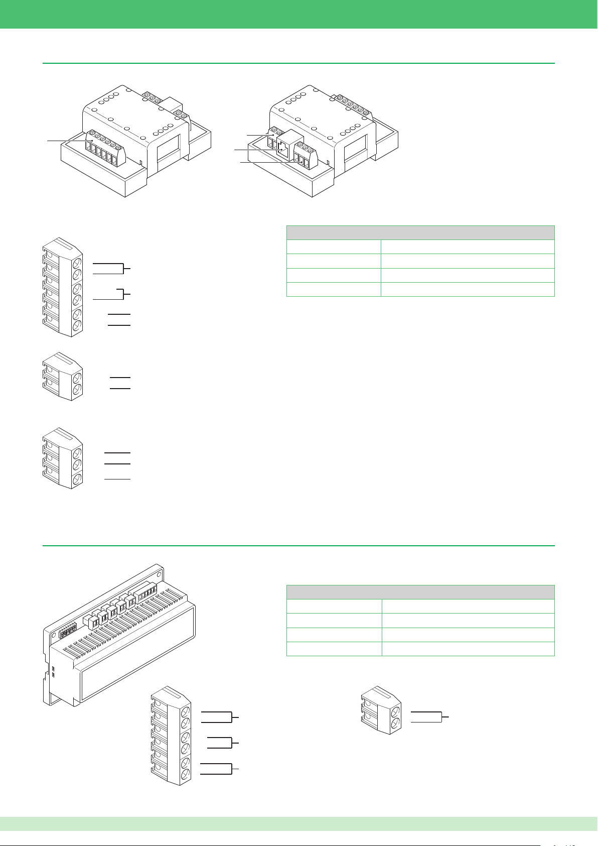
1
3
2
4
PAL / NTSC video output module Art. 1446
Module Art. 1446 provides an outgoing video signal from the system in PAL or NTSC format.
2
3
4
1. Terminal block for video outputs
C
Y
S- GND
V
COM
SPK
2. Terminal block for open collector outputs
OUT 1
OUT 2
3. Network connection Ethernet port
4. Input terminal block
IN1
COM
IN2
For wiring details, refer to the diagrams section at the end of this manual.
S-VIDEO video output terminals
CVBS video output terminals
Terminal not used
Terminal not used
Generic open collector output terminal (in closure to GND)
Terminal not used
Terminal not used
Terminal not used
Terminal not used
Technical characteristics
Absorption Min. 0.7 W Max. 2.6 W
Power supply 36/57 Vdc 3A Max.
Temperature thresholds -30 / +55°C
Dimensions 4 DIN modules / H: 3.6 cm W: 6.5 cm D: 8.3 cm
Expansion module Art. SK9071
Expansion module Art. SK9071 for use in conjunction with the IO module Art. 1443.
Technical characteristics
Absorption Min. 0.7 W Max. 2.6 W
Power supply 12 Vdc
Temperature thresholds -30 / +55°C
Dimensions 8 DIN modules / H: 5.5 cm W: 14 cm D: 9.5 cm
1. Connection terminal blocks
B
A
DD+
+
For wiring details, refer to the diagrams section at the end of this manual.
Terminals not used
Art. 1443 connection terminals
Art. 1443 12 VDC power supply terminals
B
A
J1...J10 Relay output terminals
21
Page 22
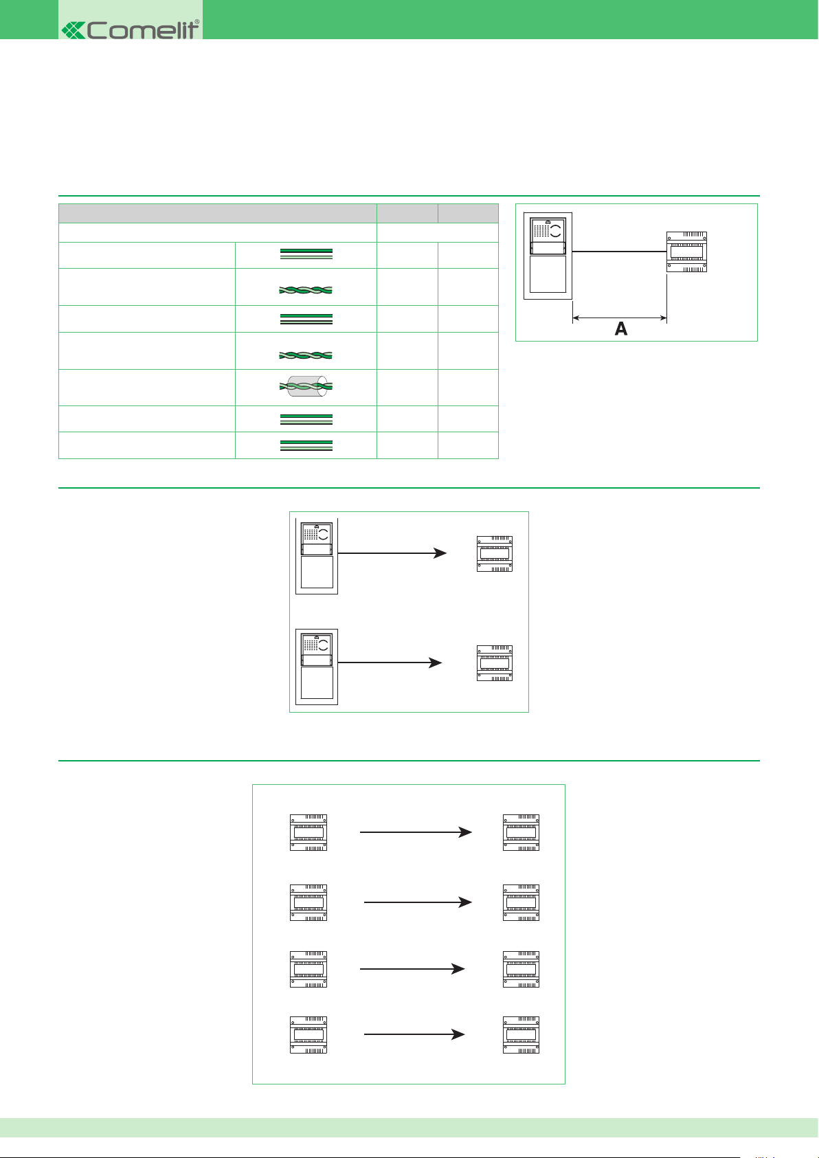
Chapter 3: System preparation and specications
Art. 1440
Art. 1440
Art. 1440
Art. 1440
Connection distances
Connection distances from power supply unit Art. 1395
Art.1395 Art.1595
0,5 mm2 (Ø 0,8 mm - AWG 20)
0,5 mm2 (Ø 0,8 mm - AWG 20)
1 mm2 (Ø 1,2 mm - AWG 17)
1 mm2 (Ø 1,2 mm - AWG 17)
1 mm2 (Ø 1,2 mm - AWG 17)
1,5 mm2 (Ø 1,4 mm - AWG 15)
2,5 mm2 (Ø 1,8 mm - AWG 13) 60 m 100 m
Comelit Art. 4576-4578
Comelit Art. 4577 / 4579
A Max
10 m 25 m
10 m 25 m
25 m 50 m
25 m 50 m
25 m 50 m
40 m 75 m
/ Art. 1595
Connection distances between external unit and Switch Art. 1440
The connection distance varies depending on the port used on Switch Art. 1440.
10 Mb
Using the 10 Mb port
250 m
to external unit
Art.1395
Art.1595
Connection distances between 2 Switches Art. 1440
The connection distance varies depending on the ports used on Switches Art. 1440.
Art. 1440
Art. 1440
Art. 1440
10 Mb
100 Mb
10 Mb
100 Mb
120 m
250 m
250 m
250 m
120 m
100 Mb
Using the 100 Mb port
10 Mb
Art. 1440
10 Mb
Art. 1440
100 Mb
Art. 1440
100 Mb
22
Page 23
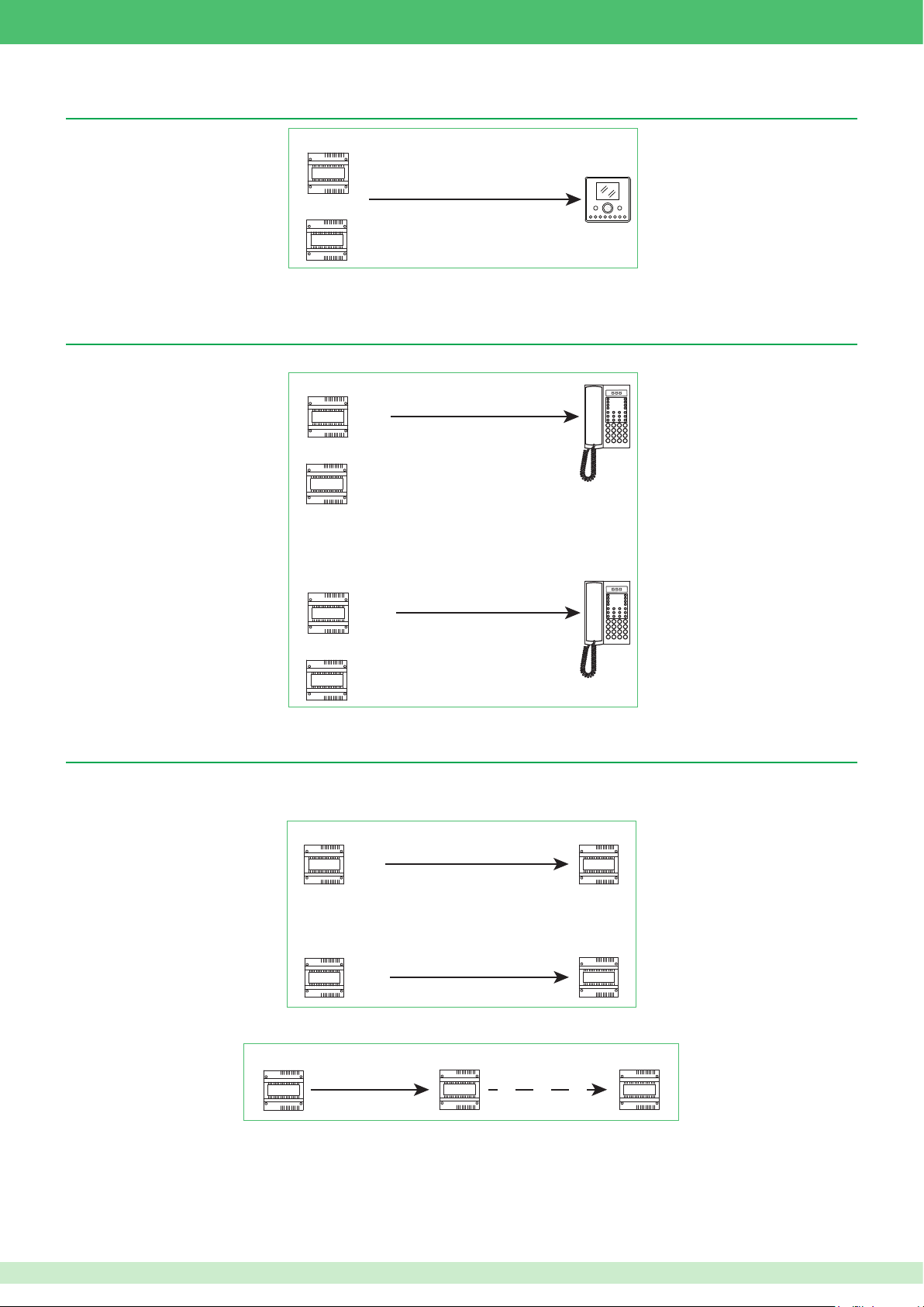
Art. 1440
Art. 1447
Art. 1440
Art. 1447
Art. 1447
Art. 1440 Art. 1447
120 m
Art. 1440
Art. 1447
120 m
Art. 1447
Art. 1447
Art. 1447
120 m
Connection distances from Switch Art. 1440 / Repeater Art. 1447 to door-entry phones / door entry monitors
250 m
Connection distances from Switch Art. 1440 / Repeater Art. 1447 to switchboard Art. 1952
The connection distance varies depending on the port used on Switch Art. 1440.
Using the 10 Mb port
10 Mb
250 m
Art. 1440
Using the 100 Mb port
100 Mb
120 m
Expanding a system using repeater Art. 1447
Repeaters Art. 1447 can be connected in series to increase the connection distance between two Switches Art. 1440 (Max. 8).
The connection distance between a Switch and a Repeater varies depending on the port used on Switch Art. 1440.
10 Mb
250 m
The connection distance between 2 Repeaters is always 120 m.
See diagram VIP/005
100 Mb
23
Page 24
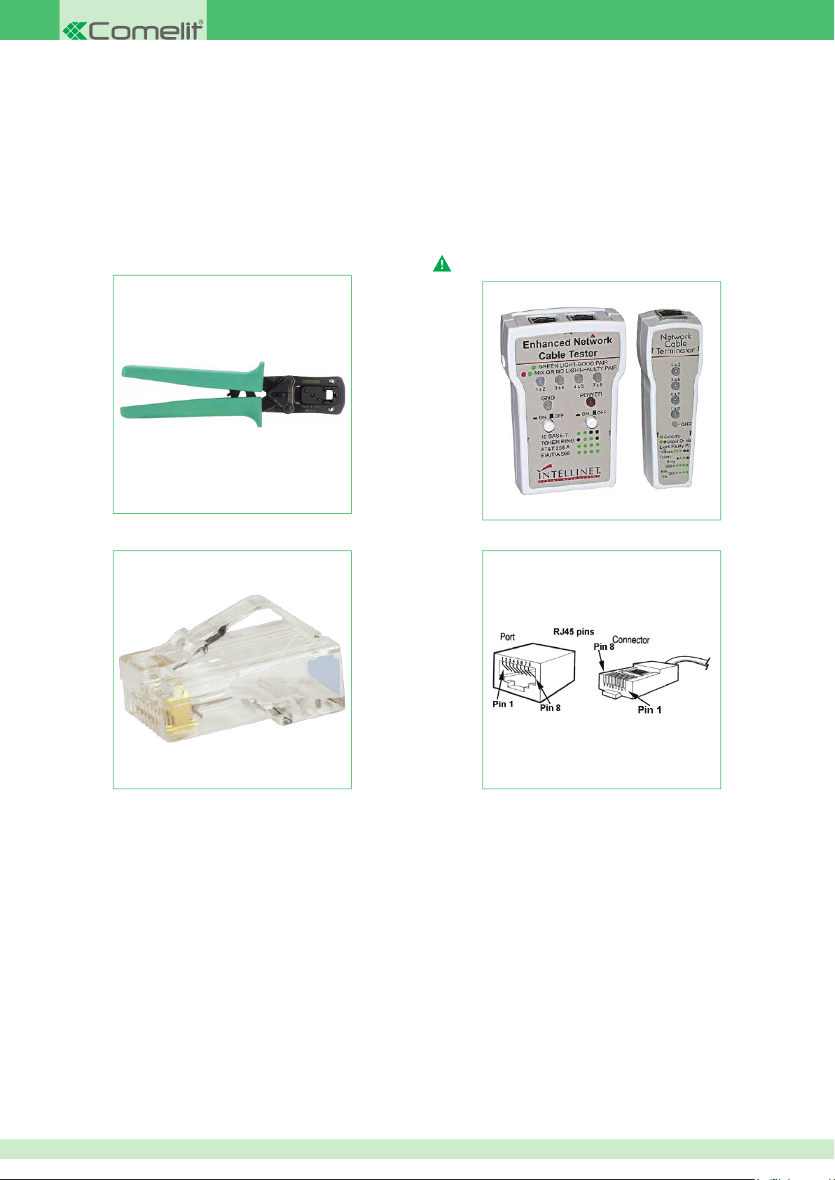
Guide to tting a UTP / STP RJ45 Direct network cable
The recommended cables are:
• UTP (Unshielded Twisted Pair):
not protected from electromagnetic interference, maximum length 100 metres.
We recommend the use of a Panduit cable code NUL5C04BU-CE.
• STP (Shielded Twisted Pair):
similar to the UTP but with a metal sheath.
The UTP and STP can fall into various categories. Category 5 (CAT 5) cables or greater must be used for the VIP system.
The tools required for tting are as follows:
• Crimping pliers 6-P 8-P.
We recommend using 8-pole Panduit pliers code MPT5-8A.
• Tester for RJ45 cables.
The tester must only be used while the system is off
• 2 RJ45 connectors for each section of cable.
We recommend using Panduit connectors code MP588-L.
24
Page 25
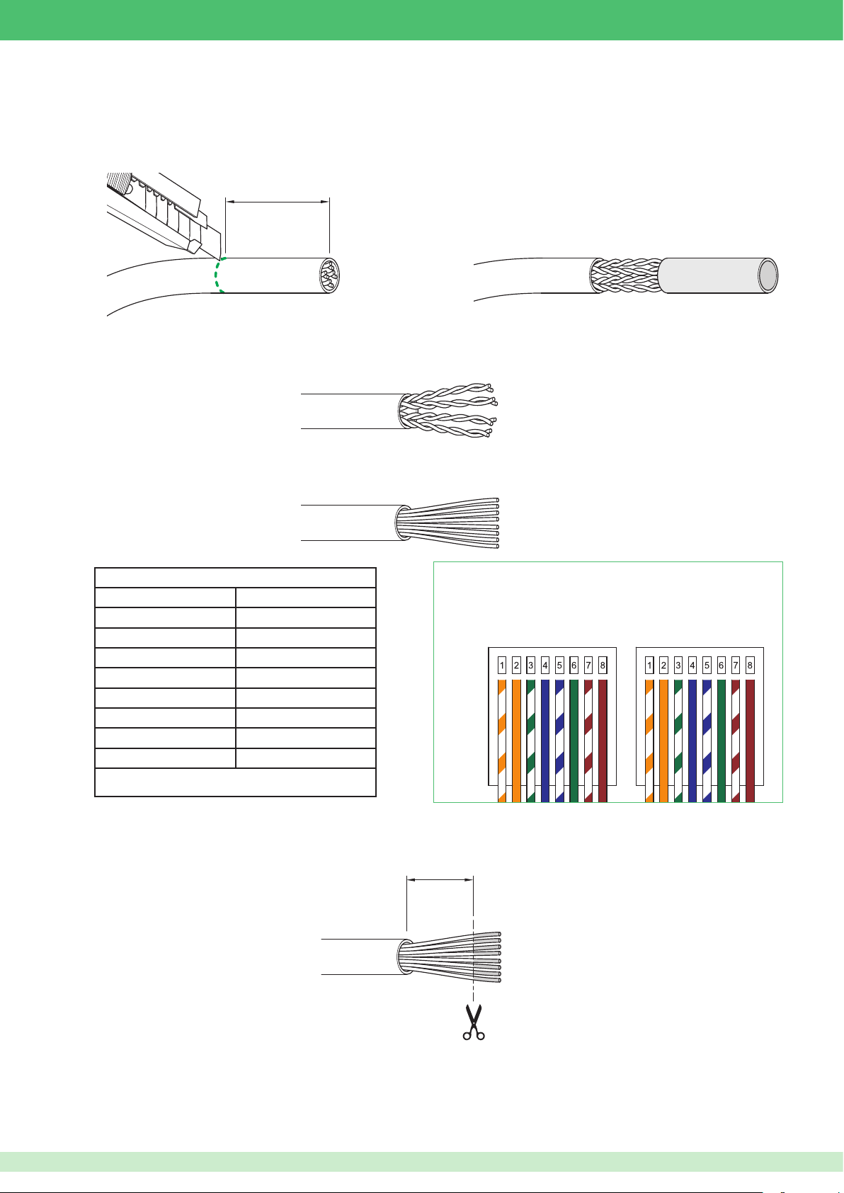
Fitting procedure
30mm
1
20mm
30mm
1
20mm
30mm
1
20mm
20mm
1. Most crimping pliers have two pairs of blades, one pair on one side to strip the wires and another pair on the other side to cut the wires. If the pliers do
not allow you to cut the cable sheath, you should use a blade and cut the sheath with it, removing a length of about three centimetres. Be especially
careful not to cut or scratch the wires inside the sheath; once cut, most sheaths break if they are folded or pulled.
30mm
1
2. When you have removed the sheath, you will have four pairs of wires, twisted together two by two and of different colours. Untwist the wire pairs so
you have 8 separate wires, but make sure you mark them if they are not of different colours (in some cables, the white/colour wires are completely
white).
3. Spread the wires out into a fan, in the order in which you need to crimp them from left to right. The cable conguration is illustrated in Table 1 and
Figure A.
Table 1
FIGURE A
Connector 1 Connector 2
White / Orange White / Orange
N.B.: if the cable colours are different, simply maintain the correct
correspondences
Orange Orange
White / Green White / Green
Blue Blue
White / Blue White / Blue
Green Green
White / Brown White / Brown
Brown Brown
4. Hold the wires tightly between two ngers and atten them so that they are side by side, then straighten them by pulling them taut with your ngers
to remove slight curves caused by the previous twisting. Make sure they stay in the correct order.
5. Continuing to hold them taut, trim the excess by 2 centimetres, so that they are all the same length.
25
Page 26
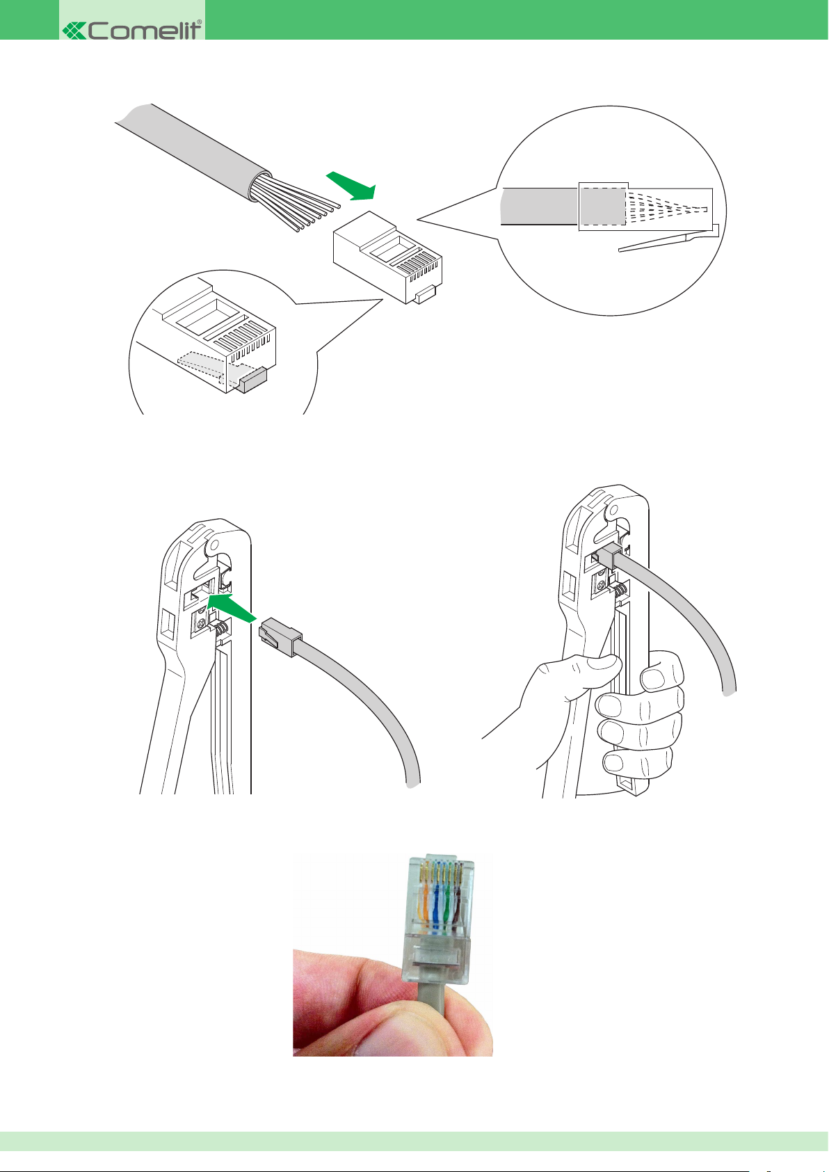
6. Insert the wires into the RJ45 connector, still holding them tightly between your ngers. The connector tab should be facing downwards and not
visible. The insulating sheath should just reach the edge of the connector.
7. Make sure the wires are fully inserted by inspecting the side of the transparent connector. Next, insert the connector into the crimping pliers and,
using both hands, crimp the connector so as to secure the wires. The pliers should not open if they did not close fully.
8. Now repeat steps 1 to 7 above, to crimp the cable on the other side.
Complete connector example
26
Page 27

Chapter 4: Mounting external units and internal units
During the installation of various products, we recommend a document is compiled to keep track of the location of the device within the
system.
An example of how to compile such a document is provided below:
Mac Address VIP Address Description
00252900082B 00002001 South gate external unit
00252900086C 00002002 North gate external unit
00252900023R 00000139 Apartment 1 internal unit
00252900052A 00000127 Smith apartment internal unit
The Mac address for the product is indicated by a label on the packaging box and another label applied directly to the product itself.
For all products, the VIP address is programmed using VIP Manager software Art. 1449, with the exception of monitors Art. 6202, Art. 6304, Art. 6501
and Art. 1952, which can be used to set the VIP address, even locally.
27
Page 28
4662C
4662C
3331/0-1-2
3337/3 - 4 - 6
4662C
3331/0-1-2
3337/3 - 4 - 6
4662C
4662C
3331/0-1-2
3331/0-1-2
5
4
2
3
1
3337/3 - 4 - 6
Mounting Powercom series external units
4662C
4662C
3331/0-1-2
3331/0-1-2
4662C
4662C
3331/0-1-2
3331/0-1-2
3337/3 - 4 - 6
4662C
4662C
3331/0-1-2
3331/0-1-2
4662C
4662C
3331/0-1-2
4662C
4662C
3331/0-1-2
3331/0-1-2
3337/3 - 4 - 6
Mounting external unit Art. 4662C and additional buttons Art. 3337/3 - 4 - 6
3331/0-1-2
3331/0-1-2
4662C
1
2
4662C
3
6
3
1
1
OPTIONAL
2
4
5
360û
360°
3337/3 - 4 - 6
4
5
7
8
3
2
9
28
Page 29
Mounting actuator module Art. 3327
PR
TX
RX
1
A B C
2
D E F
3
G H
I
4
J K L
5
M N O
6
PQRS
7
T U V
8
WXYZ
9
X
0
. , :
PR
TX
RX
PR
TX
RX
1
A B C
2
D E F
3
G H
I
4
J K L
5
M N O
6
PQRS
7
T U V
8
WXYZ
9
X
0
. , :
PR
TX
RX
PR
TX
RX
1
A B C
2
D E F
3
G H
I
4
J K L
5
M N O
6
PQRS
7
T U V
8
WXYZ
9
X
0
. , :
PR
TX
RX
1
A B C
2
D E F
3
G H
I
4
J K L
5
M N O
6
PQRS
7
T U V
8
WXYZ
9
X
0
. , :
PR
TX
RX
NC
C
NO
LP
LP
NC
C
NO
LP
LP
NC
C
NO
LP
LP
NC
C
NO
LP
LP
1
2
1
360û
360°
3
4
2
Mounting digital directory Art. 3370
3
I
G H
3
D E F
2
PQRS
6
A B C
1
M N O
5
. , :
9
J K L
4
WXYZ
8
T U V
1
2
1
360û
360°
4
3
2
3
7
0
X
29
Page 30
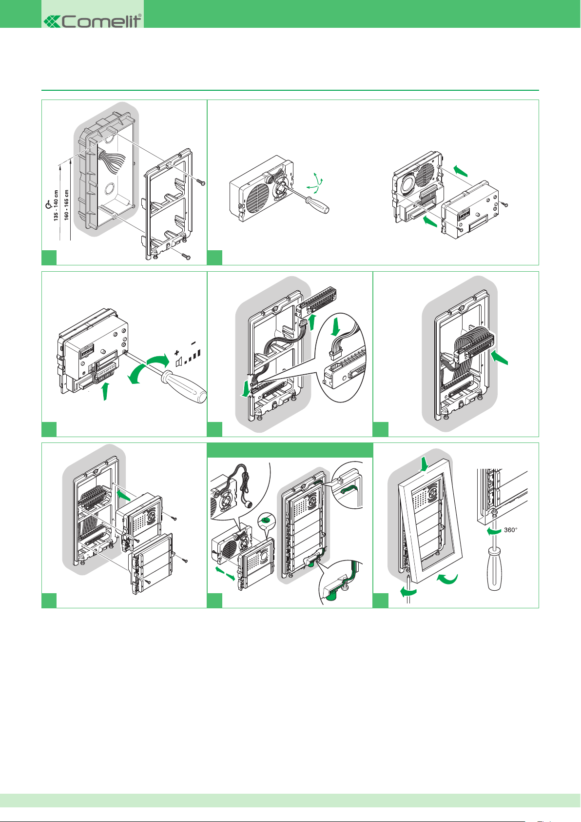
Mounting IKall series external units
4682C
4682C
3
5
2
1
4
33410
33411
33412
33410
33411
33412
4682C
1
33433
33434
33436
33410
33411
33412
4682C
33410
33411
33412
4682C
33410
33411
33412
4682C
4682C
33410
33411
33412
33410
33411
33412
4682C
33433
33434
33436
4682C
33410
33411
33412
4682C
4682C
3
5
2
1
4
33433
33410
33411
33412
4682C
4682C
33410
33411
33412
Mounting external unit Art. 4682C and additional buttons Art. 33433 - 33434 - 33436
33410
33411
4682C
33412
4682C
1
33410
33411
33412
3
4682C
2
4
OPTIONAL
3
5
1
2
4
5
1
7
6
33433
33434
33436
3 2
8
30
Page 31
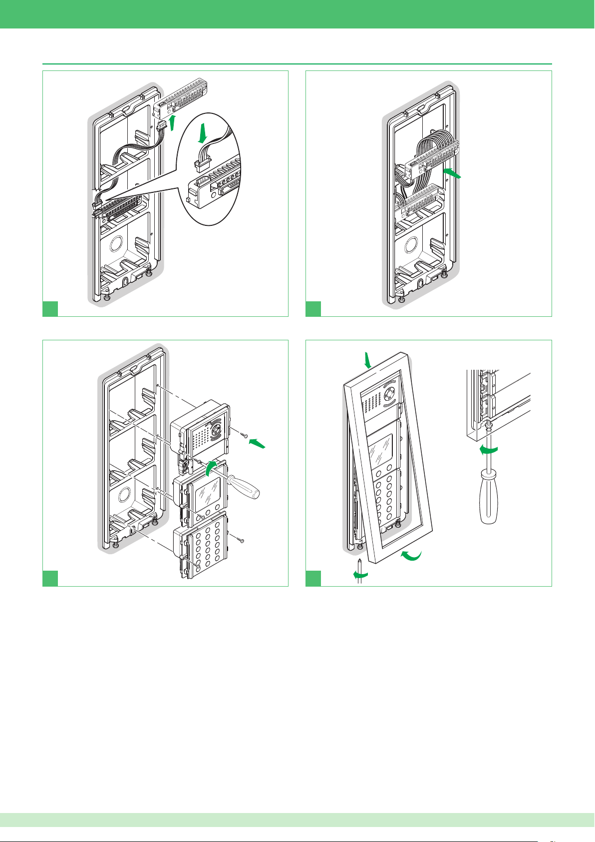
Mounting digital directory Art. 3360A
PR
TX
RX
1
A B C
2
D E F
3
G
4
J K L
5
M
N O
6
PQRS
7
T U
V
8
WXYZ
9
X
0
PR
TX
RX
PR
TX
RX
PR
TX
RX
1
A B C
2
D E F
3
G
H
I
4
J K L
5
M
N O
6
PQRS
7
T U
V
8
WXYZ
9
0
. , :
PR
TX
RX
PR
TX
RX
1
A B C
2
D E F
3
G
H
I
4
J K L
5
M
N O
6
PQRS
7
T U
V
8
WXYZ
9
X
0
. , :
PR
TX
RX
PR
TX
RX
PR
TX
RX
1
A B C
2
D E F
3
G
H
I
4
J K L
5
M
N O
6
PQRS
7
T U
V
8
WXYZ
9
X
0
. , :
PR
TX
RX
PR
TX
RX
PR
TX
RX
1
2
1
360°
3
4
3
2
31
Page 32
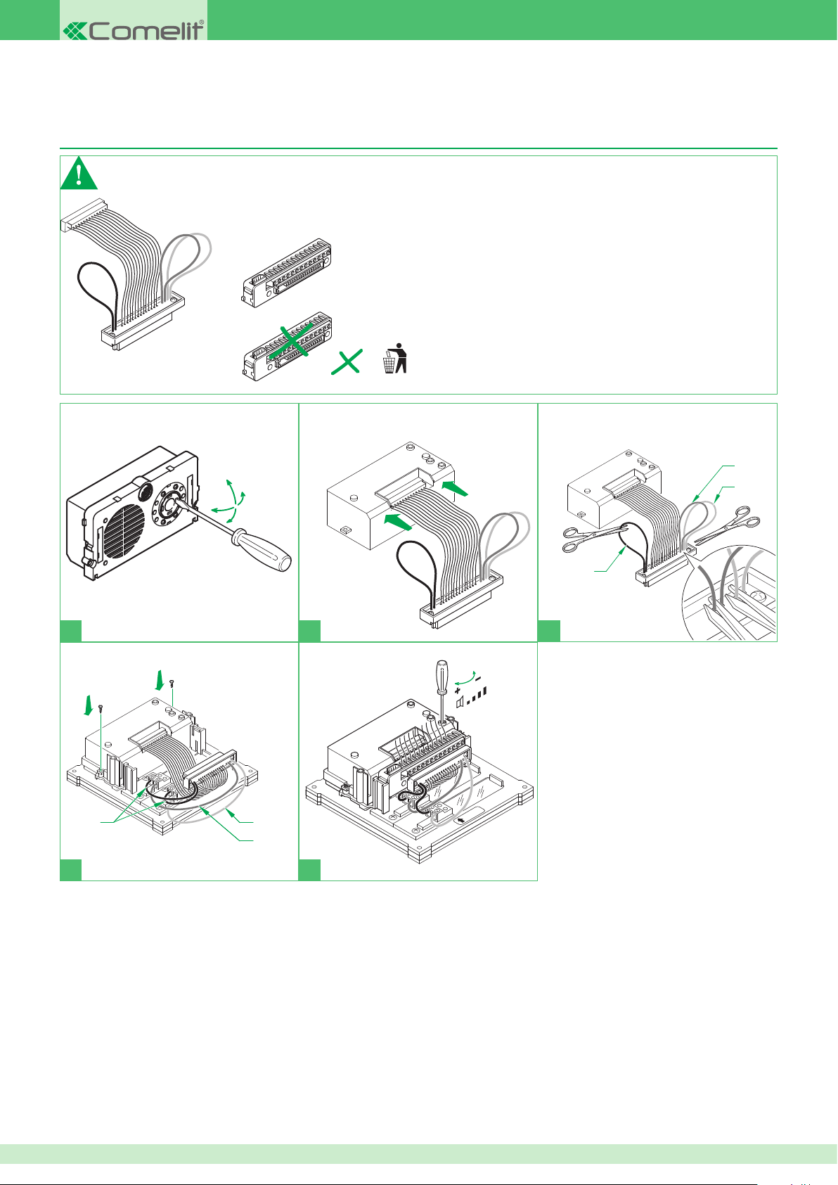
Mounting Vandalcom series external units
black
blue
orange
4662C
black
blue
orange
4662C
4662C
black
blue
orange
4662C
black
blue
orange
ALTO
3269/2
4662C
4662C
4662C
Connecting audio-video unit Art. 4662C for use with buttons on Vandalcom external unit
Art. 3269/1 - 2
Only applies to Art. 4662C
Art. 2G60000616
Art. 2G60000120 included in Art. 4662C package
=
1
black
4662C
black
4662C
ALTO
3269/2
orange
blue
2
4662C
ALTO
3269/2
3
4662C
black
blue
orange
4
5
32
Page 33
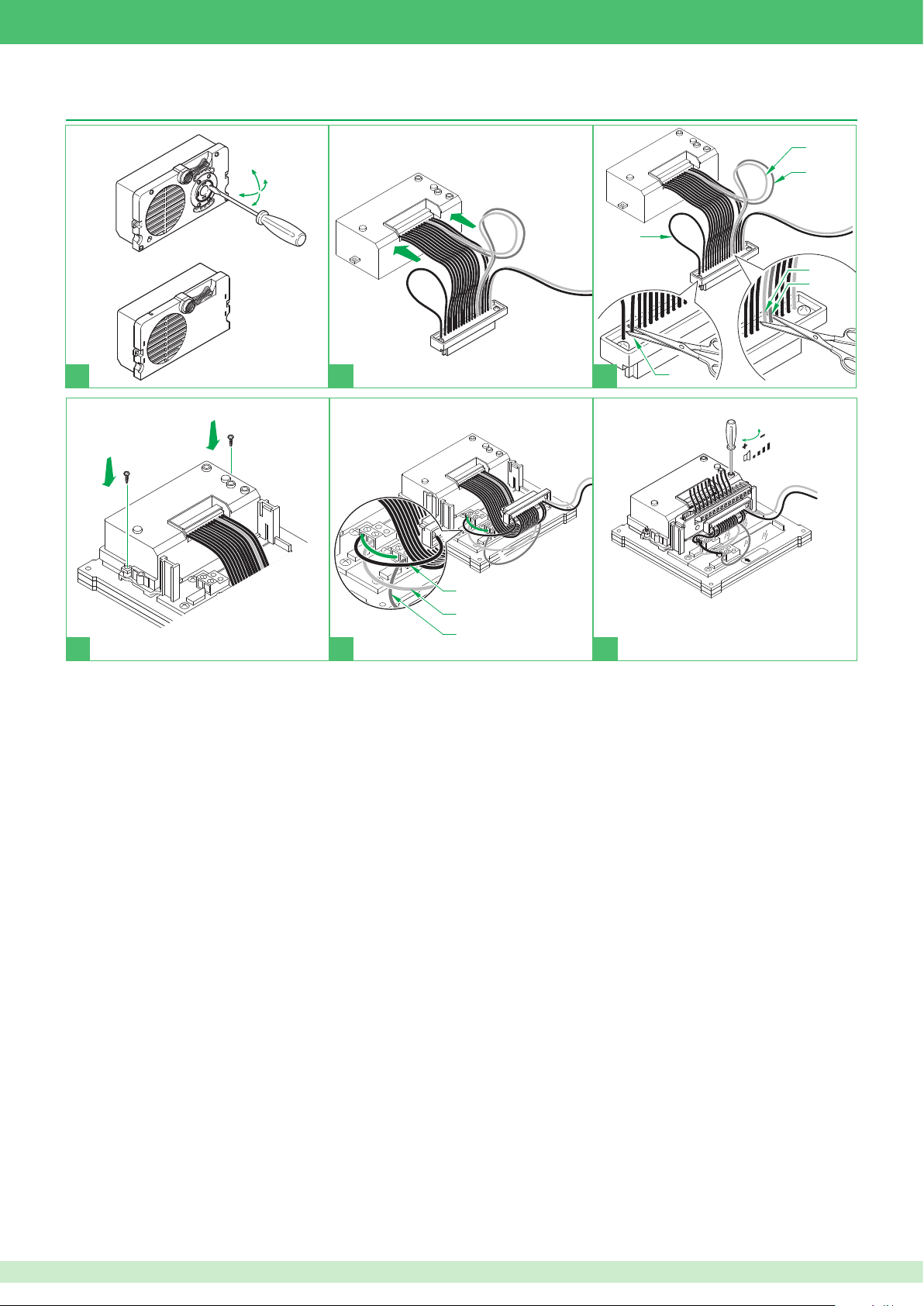
Connecting audio unit 1682 or audio-video unit Art. 4682C for use with buttons on Vandalcom
orange
white
green
white
green
4682C
1682
orange
4682C
1682
4682C
1682
orange
white
green
white
green
orange
ALTO
green
ALTO
4682C
1682
4682C
1682
3262I/2
3268I/2
white
green
white
green
orange
orange
orange
ALTO
ALTO
white
orange
4682C
1682
4682C
1682
4682C
1682
4682C
1682
4682C
1682
3262I/2
3268I/2
external unit Art. 3262I/1 - 2 and Art. 3268I/1 - 2
4682C
4682C
1682
1682
1
4682C
2
4682C
1682
1682
ALTO
3262I/2
3268I/2
ALTO
orange
white
4682C
1682
orange
3
4682C
1682
orange
ALTO
white
green
white
green
3262I/2
3268I/2
1
2
3
33
Page 34
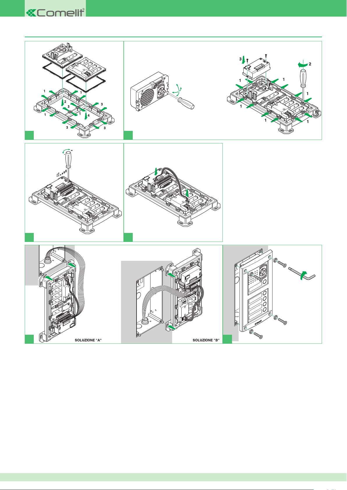
Mounting audio-video unit Art. 4662C or 4682C for use with additional buttons Art. 3064/C
1
3
2
4
5
34
6
Page 35
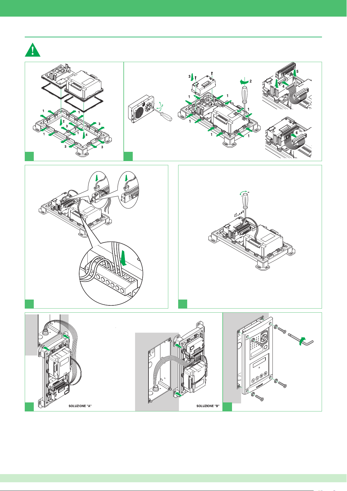
Mounting digital directories Art. 3270 - 3272 with Powercom external unit Art. 4662C
Art. 4662C
Art. 4662C
Art. 4662C
Art. 3270
Art. 3272
-
S
Art. 4662C
Art. 4662C
Art. 3270
Art. 3272
-
S
12
12
~
~
~
~
*
-
PR
Vandalcom digital directories Art. 3270 and Art. 3272 can only be connected with Powercom external unit Art. 4662C
Art. 3270
Art. 3272
1
~
~
*
12
~
12
~
3
PR
2
-
4
5
6
35
Page 36
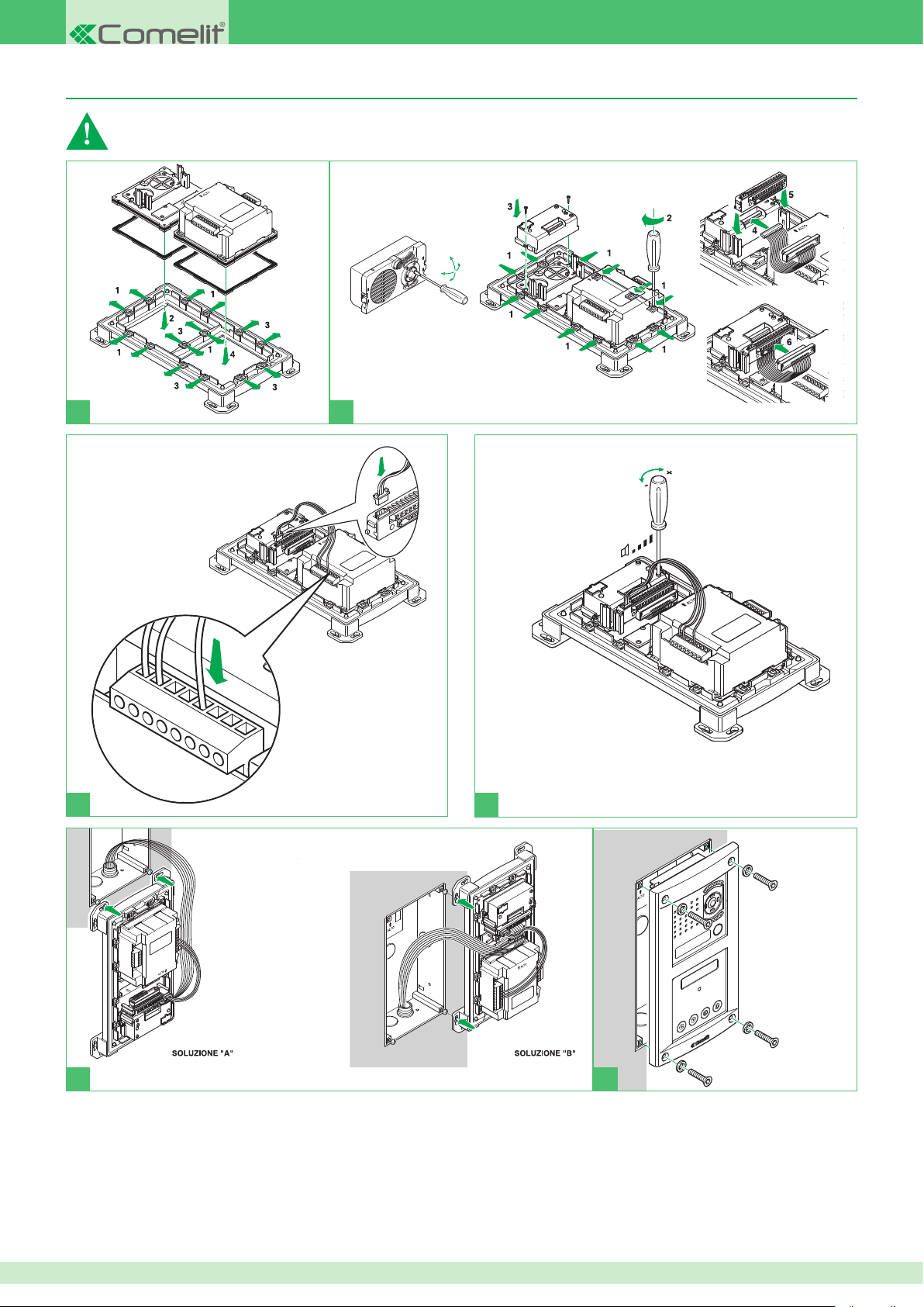
Mounting digital directories Art. 3070B - 3072B with IKall external unit Art. 4682C
Art. 4682C
4682C
Art. 4682C
4682C
Art. 3070B
Art. 3072B
Art. 4682C
4682C
V+
S
Art. 3070B
Art. 3072B
Art. 4682C
4682C
Art. 4682C
4682C
Vandalcom digital directories Art. 3070B and Art. 3072B can be connected with both IKall external unit Art. 4682C and Powercom external unit
Art. 4662C. For mounting with external unit Art. 4662C, see page 34
Art. 3070B
Art. 3072B
1
2
V-
3
4
4
3
36
Page 37
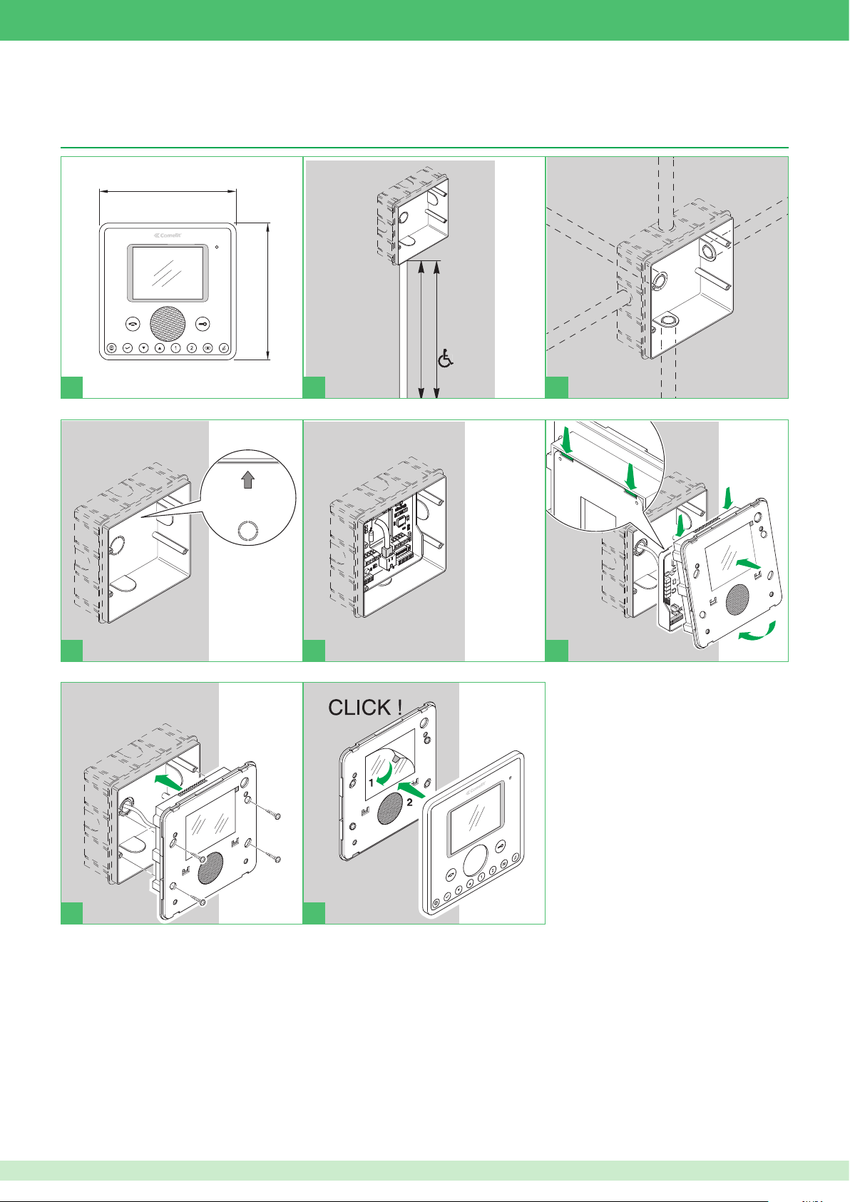
Mounting internal units
145-150 cm
115-125 cm
2
3
4
5
1
145-150 cm
115-125 cm
ALTO
UP
HAUT
OBEN
14,5 cm
14,5 cm
145-150 cm
115-125 cm
2
3
4
5
1
ALTO
UP
HAUT
OBEN
14,5 cm
14,5 cm
145-150 cm
115-125 cm
2
3
4
5
1
145-150 cm
115-125 cm
2
3
4
5
1
Mounting Planux monitor Art. 6202 with ush-mounted box Art. 6117
14,5 cm
2
14,5 cm
1 2 3
4 5 6
3
5
1
4
2
2
1
3
7 8
37
Page 38
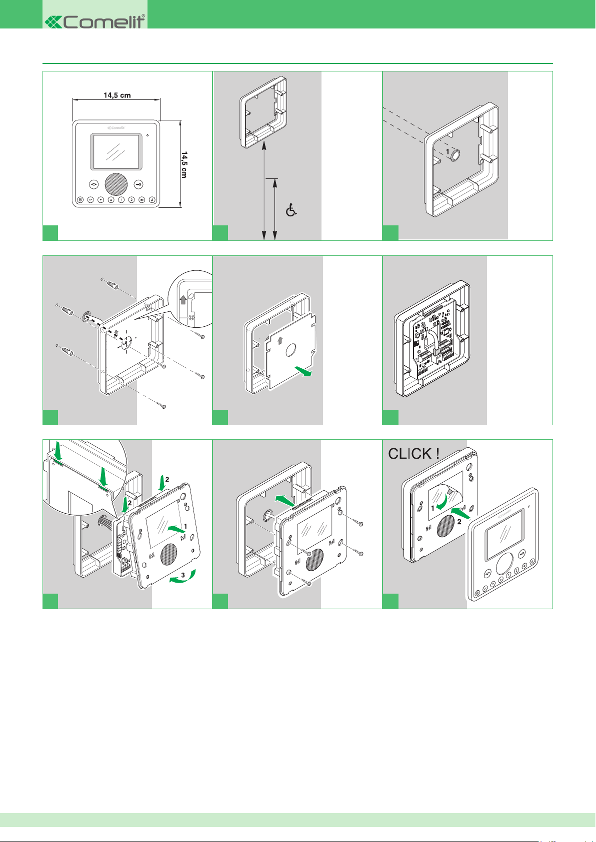
Mounting Planux monitor Art. 6202 with wall bracket Art. 6120
145-150 cm
115-125 cm
115-125 cm
145-150 cm
115-125 cm
145-150 cm
115-125 cm
145-150 cm
115-125 cm
145-150 cm
115-125 cm
145-150 cm
1 2 3
4 5 6
7 8
9
38
Page 39
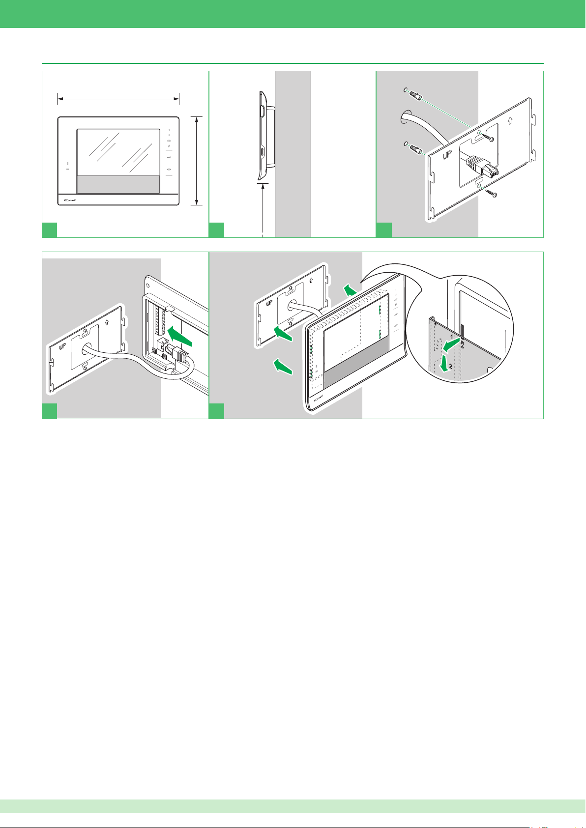
Mounting Sette Stelle monitor Art. 6501
16,7 cm
150 cm
23 cm
16,7 cm
150 cm
150 cm
23 cm
150 cm
1 2 3
4
5
39
Page 40
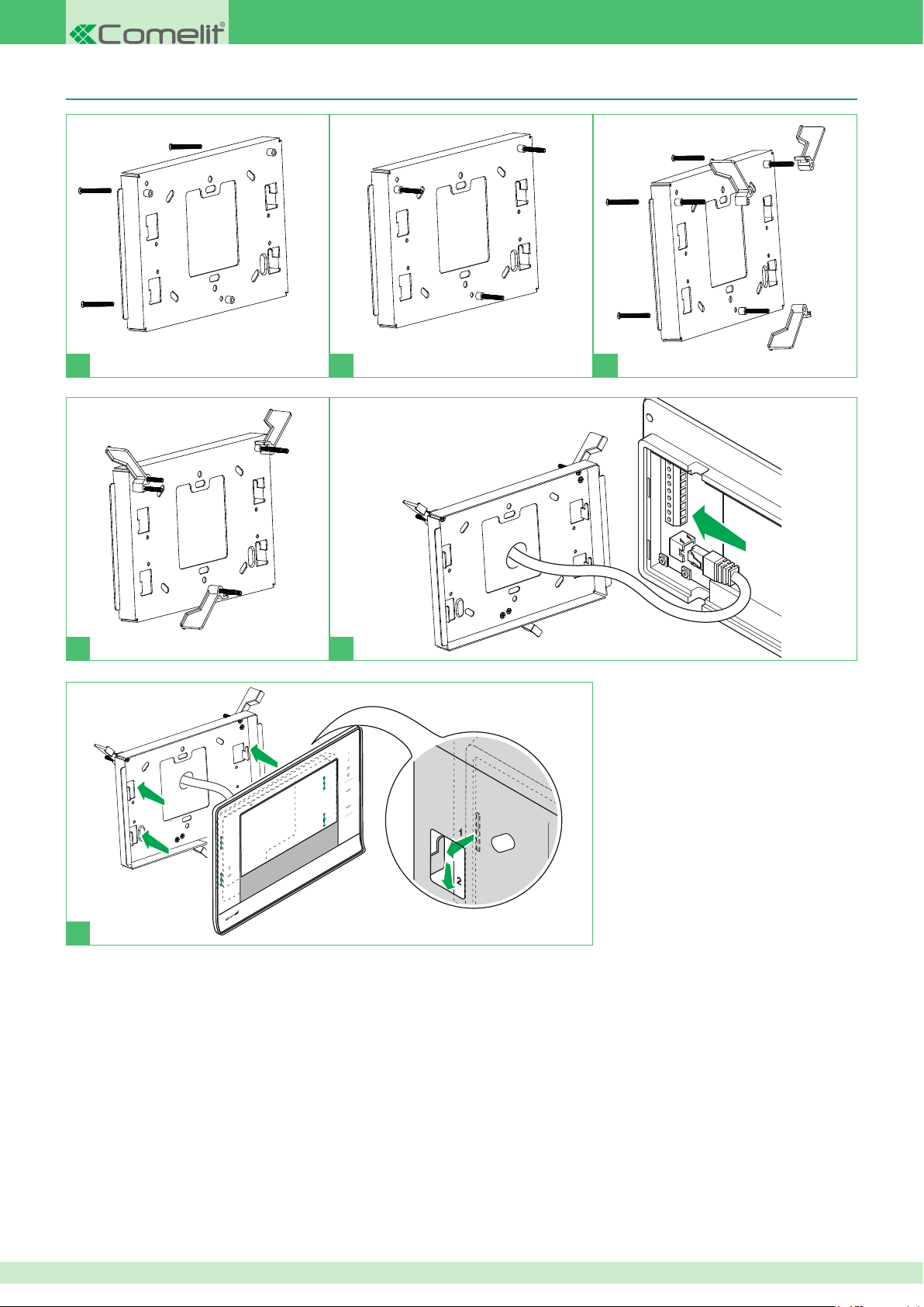
Mounting 7Stelle monitor Art. 6501 with ush-mounted box Art. 6517
1 2 3
4 5
6
40
Page 41
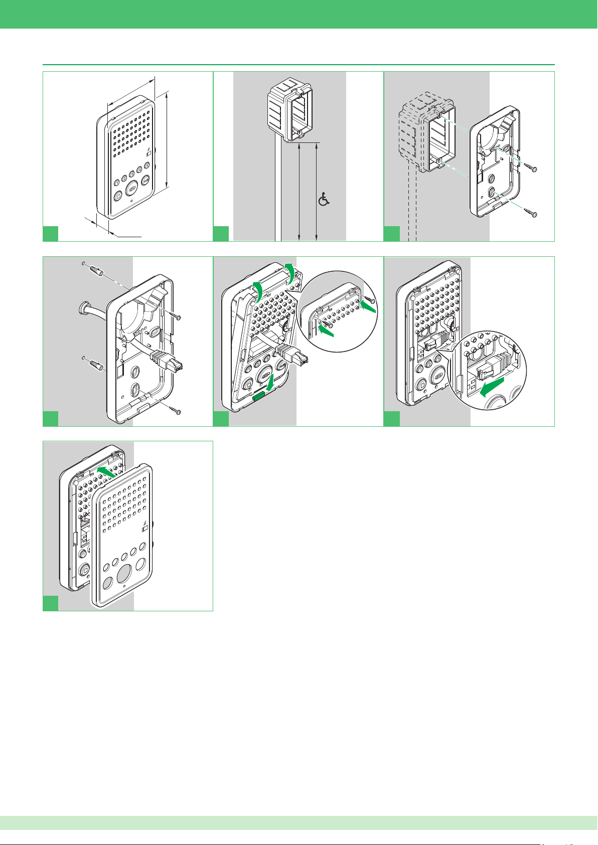
Mounting Easycom monitor Art. 6203
16 cm
9 cm
2,8 cm
115 - 125 cm
140 - 145 cm
115 - 125 cm
140 - 145 cm
2
1
2
3
3
16 cm
9 cm
2,8 cm
115 - 125 cm
140 - 145 cm
115 - 125 cm
140 - 145 cm
2
1
2
3
3
16 cm
9 cm
2,8 cm
115 - 125 cm
140 - 145 cm
1 2 3
2
2
3
3
1
4 5 6
CLICK !
7
41
Page 42
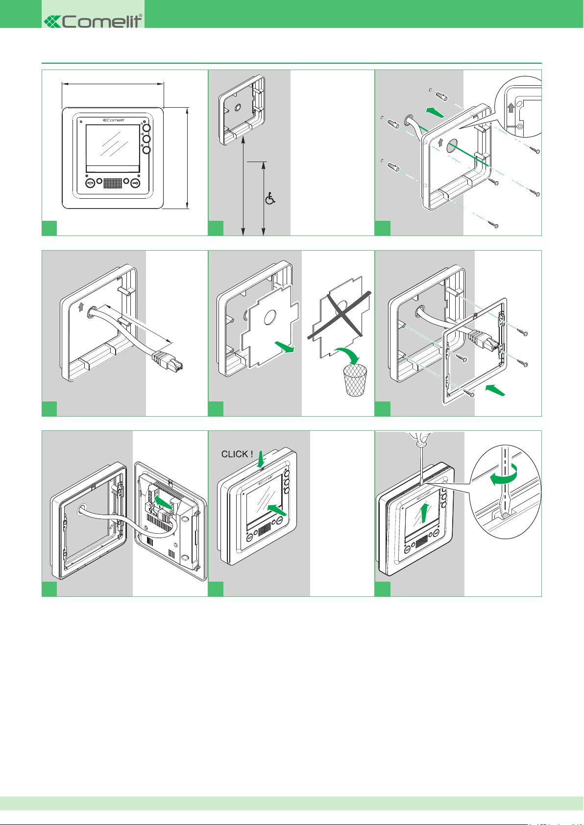
Mounting Smart monitor Art. 6304 with wall bracket Art. 6320
160 cm
130 cm
160 cm
130 cm
1
2
1
2
13,8 cm
13,8 cm
160 cm
130 cm
1
2
1
2
2
2
1
1
160 cm
130 cm
1
2
1
2
2
1
2
1
1
2
1
2
13,8 cm
13,8 cm
2
1
160 cm
130 cm
1 2 3
L
= 6,5 cm
min
L
= 7 cm
max
1
2
4 5 6
2
1
2
1
7 8
1
2
2
1
9
42
Page 43
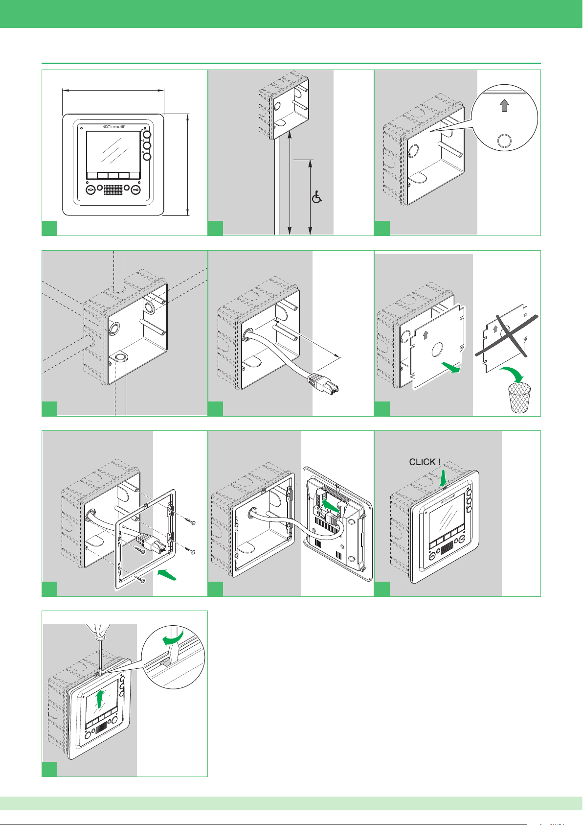
Mounting Smart monitor Art. 6304 with ush-mounted box Art. 6117
1
2
2
3
4
5
1
13,8 cm
13,8 cm
1
2
1
2
1
2
1
L
max
= 10 cm
ALTO
UP
HAUT
OBEN
2
3
4
5
1
160 cm
130 cm
13,8 cm
13,8 cm
1
2
L
min
= 6 cm
1
2
1
2
1
2
1
1
2
1
2
1
1
2
2
2
3
4
5
1
1
2
1
2
1
2
1
1
2
2
1
2
1
1
2
2
13,8 cm
13,8 cm
2
1
160 cm
130 cm
1 2 3
2
3
L
L
max
= 6 cm
min
= 10 cm
5
1
4
1
2
4 5 6
7 8
1
2
2
1
9
10
2
43
Page 44
Chapter 5: Installation programming
Mac Address
Every VIP product is identied by the factory with a unique code called the Mac address. The Mac address for the product is indicated by a label on the
packaging box and another label applied directly to the product itself.
VIP code
Each system device must be programmed with a different code, called the VIP address. The VIP address is an 8-digit code identifying each extension
and can be entered as desired, without following any pre-set sequence. However, we recommend using a logic diagram to keep track of the addresses
entered.
A logic diagram (optional) for entering the VIP address is provided below.
Example
• 01041156
• 00021022
• 01001223
• 01030009
• 00000012
During the installation of various products, we recommend a document is compiled to keep track of the location of the device within the
system.
An example of how to compile such a document is provided below:
: Building/staircase/oor/apartment
Mac Address VIP Address * Description
00252900082B 00002001 South gate external unit
00252900086C 00002002 North gate external unit
00252900023R 00000139 Apartment 1 internal unit
00252900052A 00000127 Smith apartment internal unit
* For all products, the VIP address is programmed using VIP Manager software Art. 1449, with the exception of monitors Art. 6202 and Art. 5900, which
can be used to set the VIP address, even locally.
Reset procedure for external unit Art. 4662C and 4682C
1. Cut off the power supply to the external unit.
2. Enable programming mode by moving the relevant slider.
3. Set the dip switch activation code: dip switches 1-2-3 to ON, the other dip switches to OFF.
4. Restore the power supply to external unit.
5. The external unit will now beep twice to request the conrmation code.
6. Set the dip switch conrmation code: dip switches 1-2-3 to OFF, the other dip switches to ON (i.e. the opposite of the activation code).
7. Exit programming mode by moving the relevant slider.
8. The external unit will now beep for 2-3 seconds to indicate that the conguration has been reset.
9. When the beep has ended, the external unit will start up with its factory set conguration values.
44
Page 45
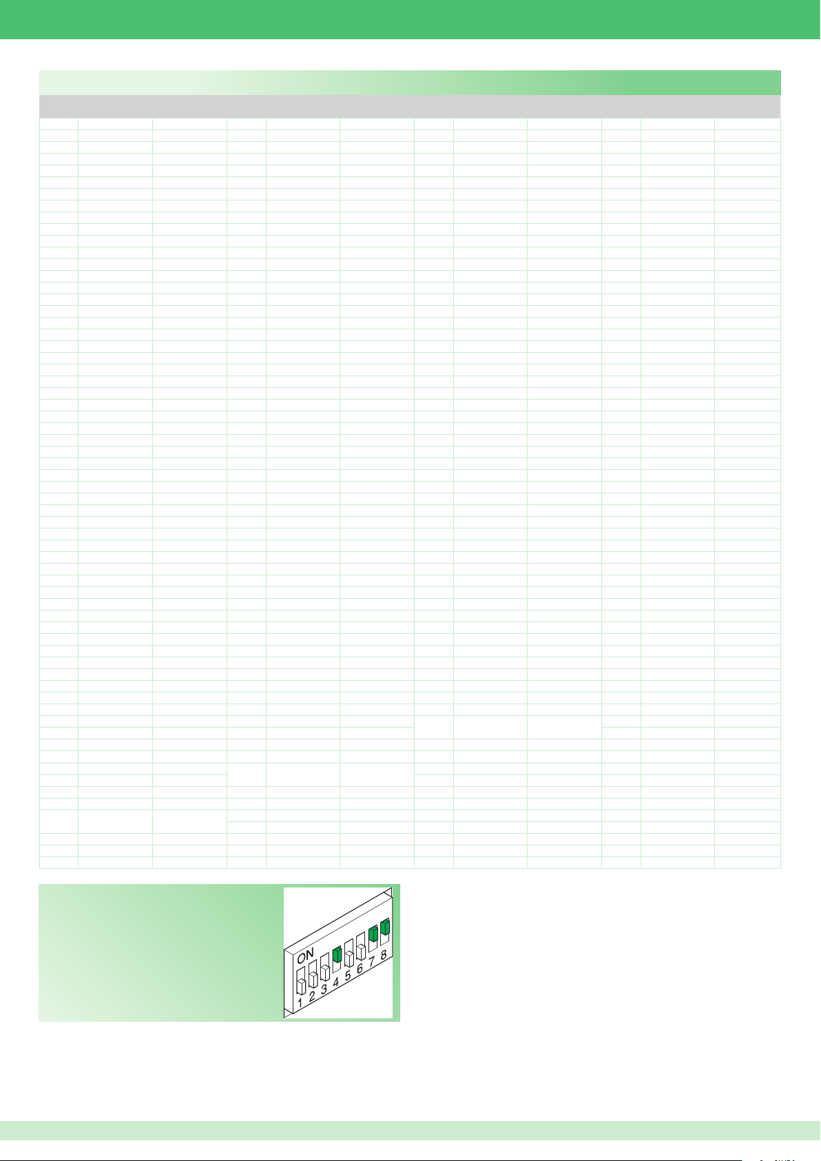
Dip switch programming table
Codice /
Code
1 1
Dip switch ON Nome / Name
Codice /
Dip switch ON Nome / Name
Code
65 1.7 129 1.8 193 1,7,8
2 2 66 2.7 130 2.8 194 2,7,8
3 1.2 67 1,2,7 131 1,2,8 195 1,2,7,8
4 3 68 3.7 132 3.8 196 3,7,8
5 1.3 69 1,3,7 133 1,3,8 197 1,3,7,8
6 2.3 70 2,3,7 134 2,3,8 198 2,3,7,8
7 1,2,3 71 1,2,3,7 135 1,2,3,8 199 1,2,3,7,8
8 4 72 4.7 136 4.8 200 4,7,8
9 1.4 73 1,4,7 137 1,4,8 201 1,4,7,8
10 2.4 74 2,4,7 138 2,4,8 202 2,4,7,8
11 1,2,4 75 1,2,4,7 139 1,2,4,8 203 1,2,4,7,8
12 3.4 76 3,4,7 140 3,4,8 204 3,4,7,8
13 1,3,4 77 1,3,4,7 141 1,3,4,8 205 1,3,4,7,8
14 2,3,4 78 2,3,4,7 142 2,3,4,8 206 2,3,4,7,8
15 1,2,3,4 79 1,2,3,4,7 143 1,2,3,4,8 207 1,2,3,4,7.8
16 5 80 5.7 144 5.8 208 5,7,8
17 1.5 81 1,5,7 145 1,5,8 209 1,5,7,8
18 2.5 82 2,5,7 146 2,5,8 210 2,5,7,8
19 1,2,5 83 1,2,5,7 147 1,2,5,8 2 11 1,2,5,7,8
20 3.5 84 3,5,7 148 3,5,8 212 3,5,7,8
21 1,3,5 85 1,3,5,7 149 1,3,5,8 213 1,3,5,7,8
22 2,3,5 86 2,3,5,7 150 2,3,5,8 214 2,3,5,7,8
23 1,2,3,5 87 1,2,3,5,7 151 1,2,3,5,8 215 1,2,3,5,7.8
24 4.5 88 4,5,7 152 4,5,8 216 4,5,7,8
25 1,4,5 89 1,4,5,7 153 1,4,5,8 217 1,4,5,7,8
26 2,4,5 90 2,4,5,7 154 2,4,5,8 218 2,4,5,7,8
27 1,2,4,5 91 1,2,4,5,7 155 1,2,4,5,8 219 1,2,4,5,7.8
28 3,4,5 92 3,4,5,7 156 3,4,5,8 220 3,4,5,7,8
29 1,3,4,5 93 1,3,4,5,7 157 1,3,4,5,8 221 1,3,4,5,7.8
30 2,3,4,5 94 2,3,4,5,7 158 2,3,4,5,8 222 2,3,4,5,7.8
31 1,2,3,4,5 95 1,2,3,4,5.7 159 1,2,3,4,5.8 223 1,2,3,4,5,7,8
32 6 96 6.7 160 6.8 224 6,7,8
33 1.6 97 1,6,7 161 1,6,8 225 1,6,7,8
34 2.6 98 2,6,7 162 2,6,8 226 2,6,7,8
35 1,2,6 99 1,2,6,7 163 1,2,6,8 227 1,2,6,7,8
36 3.6 100 3,6,7 164 3,6,8 228 3,6,7,8
37 1,3,6 101 1,3,6,7 165 1,3,6,8 229 1,3,6,7,8
38 2,3,6 102 2,3,6,7 166 2,3,6,8 230 2,3,6,7,8
39 1,2,3,6 103 1,2,3,6,7 167 1,2,3,6,8 231 1,2,3,6,7.8
40 4.6 104 4,6,7 168 4,6,8 232 4,6,7,8
41 1,4,6 105 1,4,6,7 169 1,4,6,8 233 1,4,6,7,8
42 2,4,6 106 2,4,6,7 170 2,4,6,8 234 2,4,6,7,8
43 1,2,4,6 107 1,2,4,6,7 171 1,2,4,6,8 235 1,2,4,6,7.8
44 3,4,6 108 3,4,6,7 172 3,4,6,8 236 3,4,6,7,8
45 1,3,4,6 109 1,3,4,6,7 173 1,3,4,6,8 237 1,3,4,6,7.8
46 2,3,4,6 110 2,3,4,6,7 174 2,3,4,6,8 238 2,3,4,6,7.8
47 1,2,3,4,6 111 1,2,3,4,6.7 175 1,2,3,4,6.8 239 1,2,3,4,6,7,8
48 5.6 112 5.67 176 5,6,8 240 5,6,7,8
49 1,5,6 113 1,5,6,7 177 1,5,6,8 241 1,5,6,7,8
50 2,5,6 114 2,5,6,7 178 2,5,6,8 242 2,5,6,7,8
51 1,2,5,6 115 1,2,5,6,7 179 1,2,5,6,8 243 1,2,5,6,7.8
52 3,5,6 116 3,5,6,7
53 1,3,5,6 117 1,3,5,6,7
54 2,3,5,6 118 2,3,5,6,7 182 2,3,5,6,8 246 2,3,5,6,7.8
55 1,2,3,5,6 119 1,2,3,5,6.7 183 1,2,3,5,6.8 247 1,2,3,5,6,7,8
56 4,5,6
57 1,4,5,6
120 4,5,6,7
121 1,4,5,6,7
58 2,4,5,6 122 2,4,5,6,7 186 2,4,5,6,8 250 2,4,5,6,7.8
59 1,2,4,5,6 123 1,2,4,5,6.7 187 1,2,4,5,6.8 251 1,2,4,5,6,7,8
60 3,4,5,6
61 1,3,4,5,6
124 3,4,5,6,7 188 3,4,5,6,8 252 3,4,5,6,7.8
125 1,3,4,5,6.7 189 1,3,4,5,6.8 253 1,3,4,5,6,7,8
62 2,3,4,5,6 126 2,3,4,5,6.7 190 2,3,4,5,6.8 254 2,3,4,5,6,7,8
63 1,2,3,4,5.6 127 1,2,3,4,5,6,7 191 1,2,3,4,5,6,8 255 1,2,3,4,5,6,7.8
64 7 128 8 192 7.8
Codice /
Dip switch ON Nome / Name
Code
180 3,5,6,8
181 1,3,5,6,8
Codice /
Dip switch ON Nome / Name
Code
244 3,5,6,7,8
245 1,3,5,6,7.8
184 4,5,6,8 248 4,5,6,7,8
185 1,4,5,6,8 249 1,4,5,6,7.8
EXAMPLE setting code 200.
45
Page 46
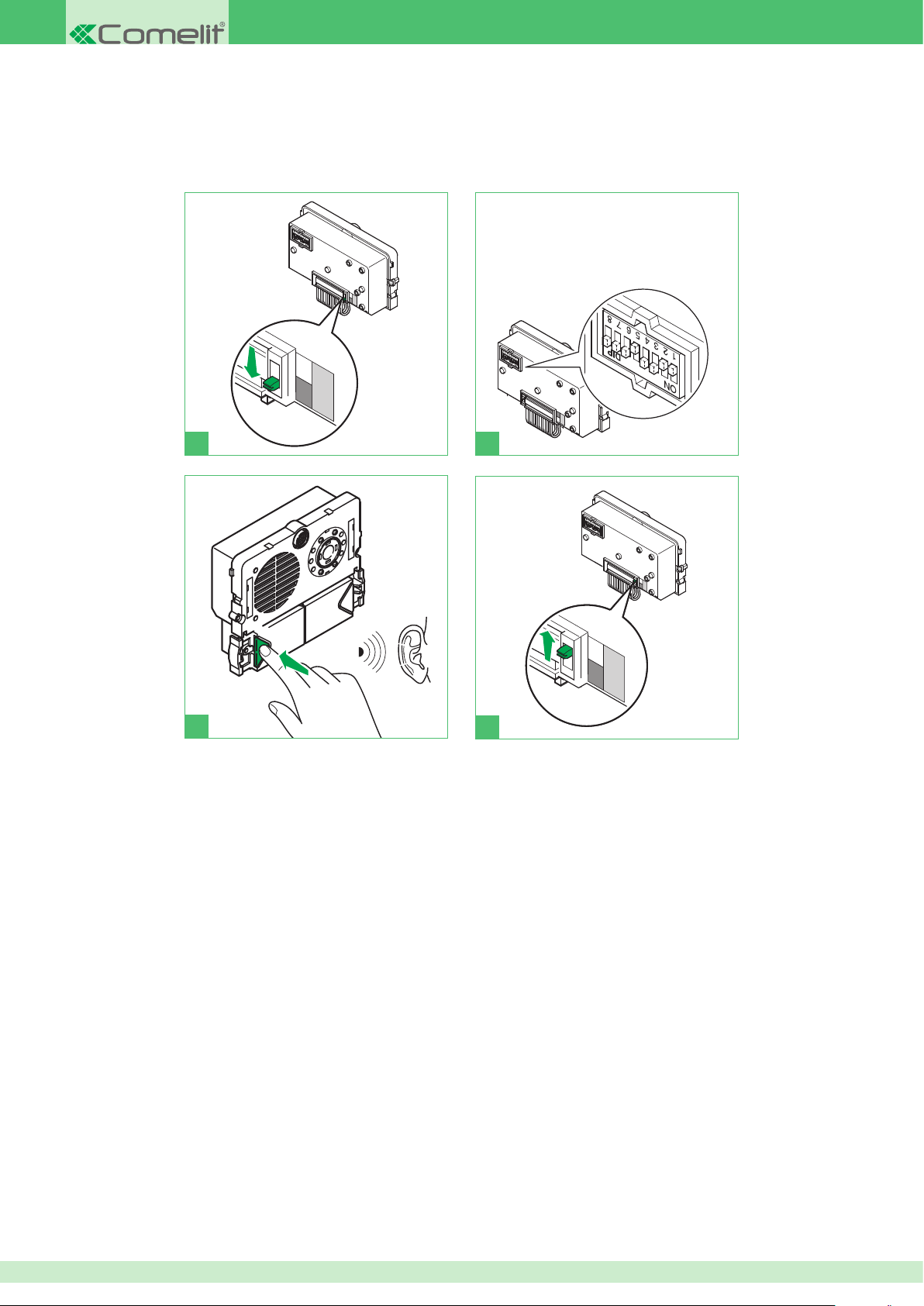
Manually programming buttons on external unit Art. 4662C
The following procedure can be used to program buttons with VIP codes in the range between 1 and 255 only.
To program higher VIP addresses, use VIP Manager software Art. 1449.
1. Perform the wiring for the external unit.
2. Power up the external unit, carry out steps (1-4).
Set the Dip switch on the rear of the module
Art. 4662C with the same code assigned to the
internal unit, in accordance with the information
provided in the programming table on page 45.
PR
1 2
PR
3
4
46
Page 47
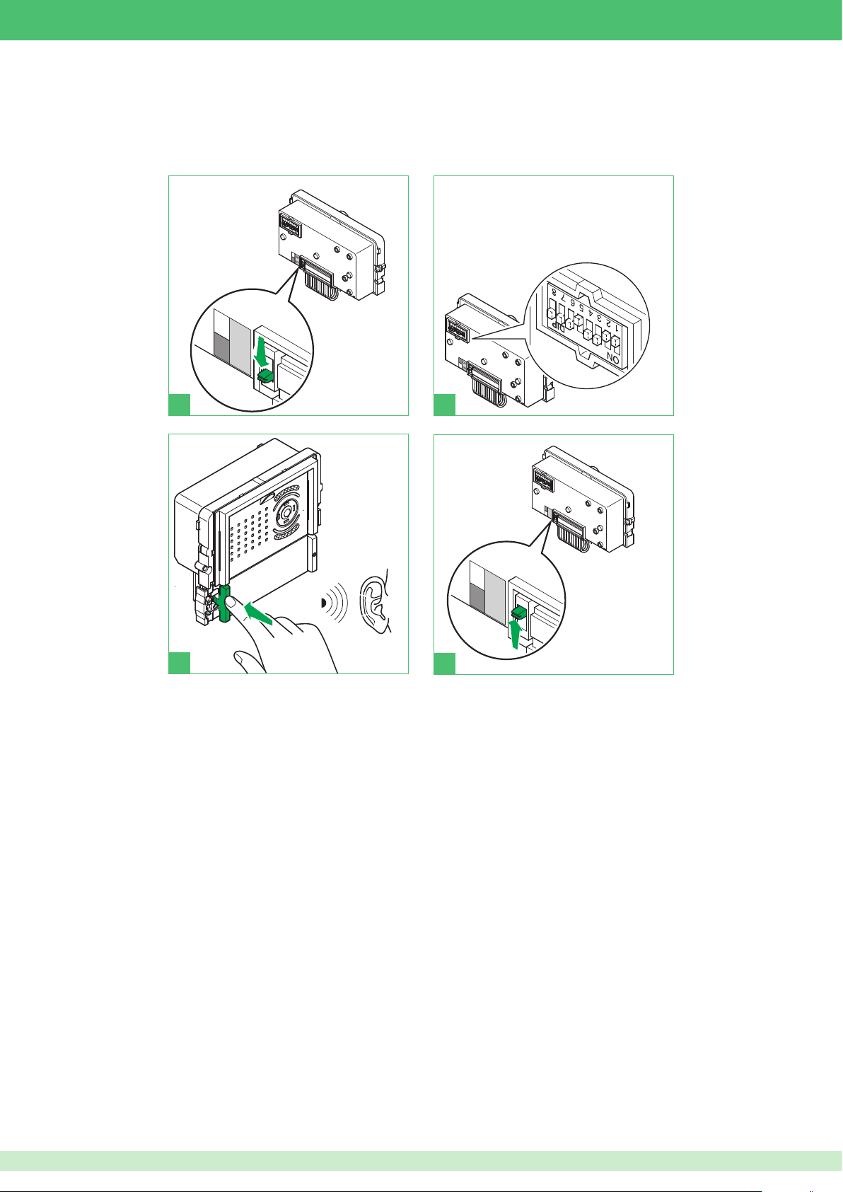
Manually programming buttons on external unit Art. 4682C
The following procedure can be used to program buttons with VIP codes in the range between 1 and 255 only.
To program higher VIP addresses, use VIP Manager software Art. 1449.
1. Perform the wiring for the external unit.
2. Power up the external unit, carry out steps (1-4).
Set the Dip switch on the rear of the module
Art. 4682C with the same code assigned to the
internal unit, in accordance with the information
provided in the programming table on page 45.
PR
1 2
PR
3
4
47
Page 48
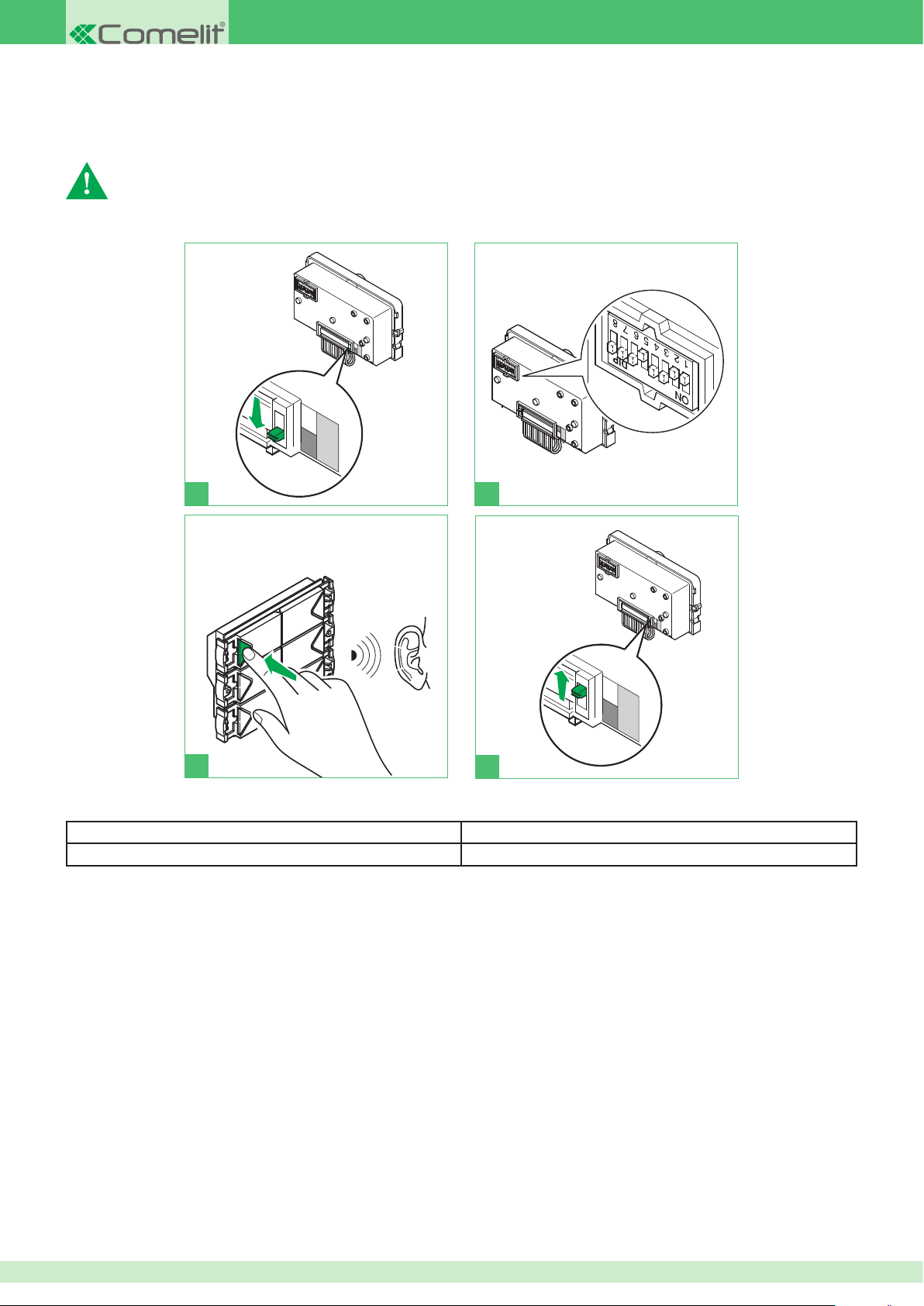
Assigning module index to additional button products
Art. 3337/3 - 4 - 6
Follow the procedure below for each module Art. 3337 connected to the system.
This procedure is used to assign an index to modules Art. 3337. The module index must then be used with the VIP Manager software
to complete module programming (see manual for VIP Manager software Art. 1449).
1. Perform module and button wiring.
2. Power up the external unit, carry out steps (1-4).
Set the Module index code using
the dip switches, see table on
page 45.
PR
1 2
PR
3
Make a note of the address which has just been set on module Art. 3337 and the VIP address of the external unit to which it is connected,
as in the following example.
Art. 4662C VIP address Art. 3337 Module index
00000600 236
4
48
Page 49
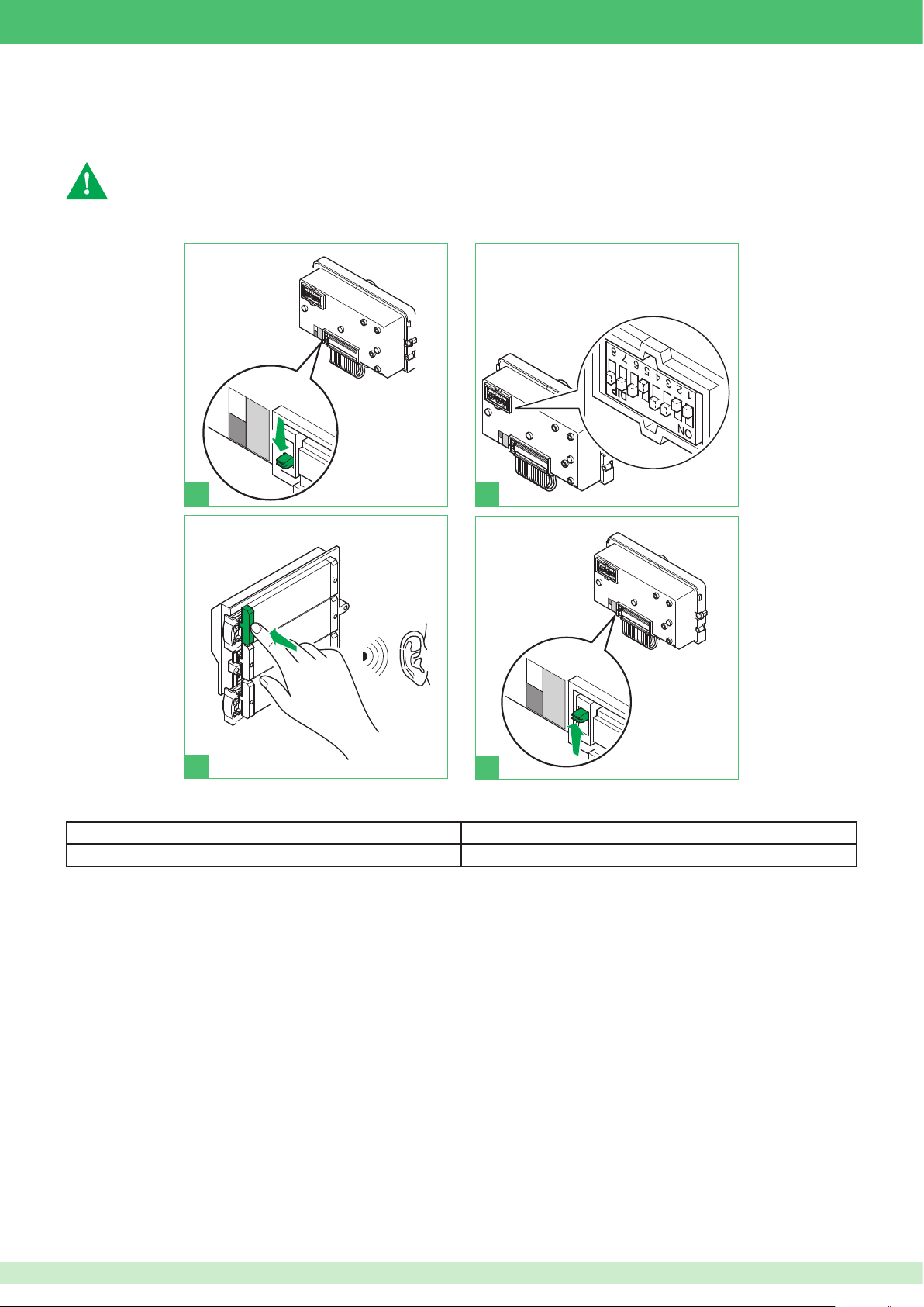
Assigning module index to additional button products
Art. 33433 - 33434 - 33436
Follow the procedure below for each module Art. 3343 connected to the system.
This procedure is used to assign an index to modules Art. 3343. The module index must then be used with the VIP Manager software
to complete module programming (see manual for VIP Manager software Art. 1449).
1. Perform module and button wiring.
2. Power up the external unit, carry out steps (1-4).
Set the Module index code using
the dip switches, see table on
page 45.
PR
1 2
PR
3
Make a note of the address which has just been set on module Art. 3337 and the VIP address of the external unit to which it is connected,
as in the following example.
Art. 4682C VIP address
00000600 236
4
Art. 3337 Module index
49
Page 50
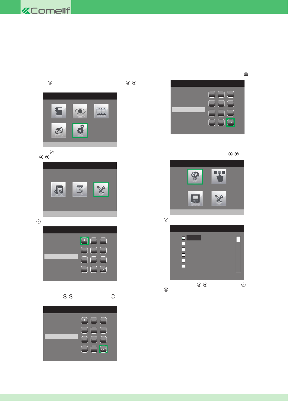
Programming internal units
LANGUAGES MENU
We recommend using VIP Manager software Art. 1459 to program the internal units. However, the main parameters of some internal units (Planux,
7Stelle, Smart and CPS) can be set directly on the product itself, where necessary.
Planux monitor Art. 6202 and Smart monitor Art. 6304 (only with optional buttons Art. 6332)
• Accessing the installer menu
1. Press button and select the Settings menu using buttons , .
MAIN MENU
Settings
2. Press button to access and select the Installer menu using
buttons
3. Press
, .
SETTINGS MENU
Installer menu
to access it.
ENTER PASSWORD
5. When you have nished entering digits, select the icon
ENTER PASSWORD
2 3
1
5 6
4
****
8 9
7
C
0
• Setting the menu language
1. Access the installer menu.
2. Select the Set language menu using buttons
INSTALLER MENU
Set language
3. Press to access it.
, .
.
2 3
1
5 6
4
8 9
7
C
0
The password for the installer menu is 0000. The password cannot
be changed.
4. Select the digits using
, and enter by pressing .
ENTER PASSWORD
1
4
****
7
C
2 3
5 6
8 9
0
Italiano
English
Franḉais
Español
Português
Deutsch
4. Select the language using , and set by pressing .
5. Press to exit and save the changes.
50
Page 51
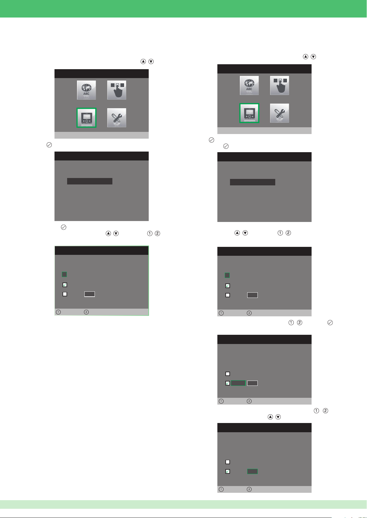
• Programming the VIP code for main
Planux monitors
1. Access the installer menu.
2. Select the Con gure monitor menu using buttons , .
INSTALLER MENU
• Programming the VIP code for secondary
Planux monitors
1. Access the installer menu.
2. Select the Con gure monitor menu using buttons , .
INSTALLER MENU
Configure monitor
3. Press
to access it.
CONFIGURE MONITOR
ViP address
About
Reset configuration
4. Press button
5. Change the address using buttons
from one digit to the next.
to access the VIP address menu.
CONFIGURE VIP ADDRESS
ViP address
0
0 0 0 0 0 0 1
Master
Slave
0 0
, . Use buttons , to pass
Configure monitor
3. Press
4. Press button to access the VIP address menu.
to access it.
CONFIGURE MONITOR
ViP address
About
Reset configuration
5. Set the logic address for the main monitor in the same residential
unit using buttons
to the next.
, . Use buttons , to pass from one digit
CONFIGURE VIP ADDRESS
ViP address
0
0 0 0 0 0 0 1
Master
Slave
0 0
Left Right
Left Right
6. Move over the Slave option using buttons
con rm.
CONFIGURE VIP ADDRESS
ViP address
0
0 0 0 0 0 0 1
Master
Slave
0 0
Left Right
7. Move over the Slave address option using buttons
change the address using buttons
CONFIGURE VIP ADDRESS
ViP address
0
0 0 0 0 0 0 1
Master
Slave
0 1
Left Right
, .
, and press to
, and
51
Page 52
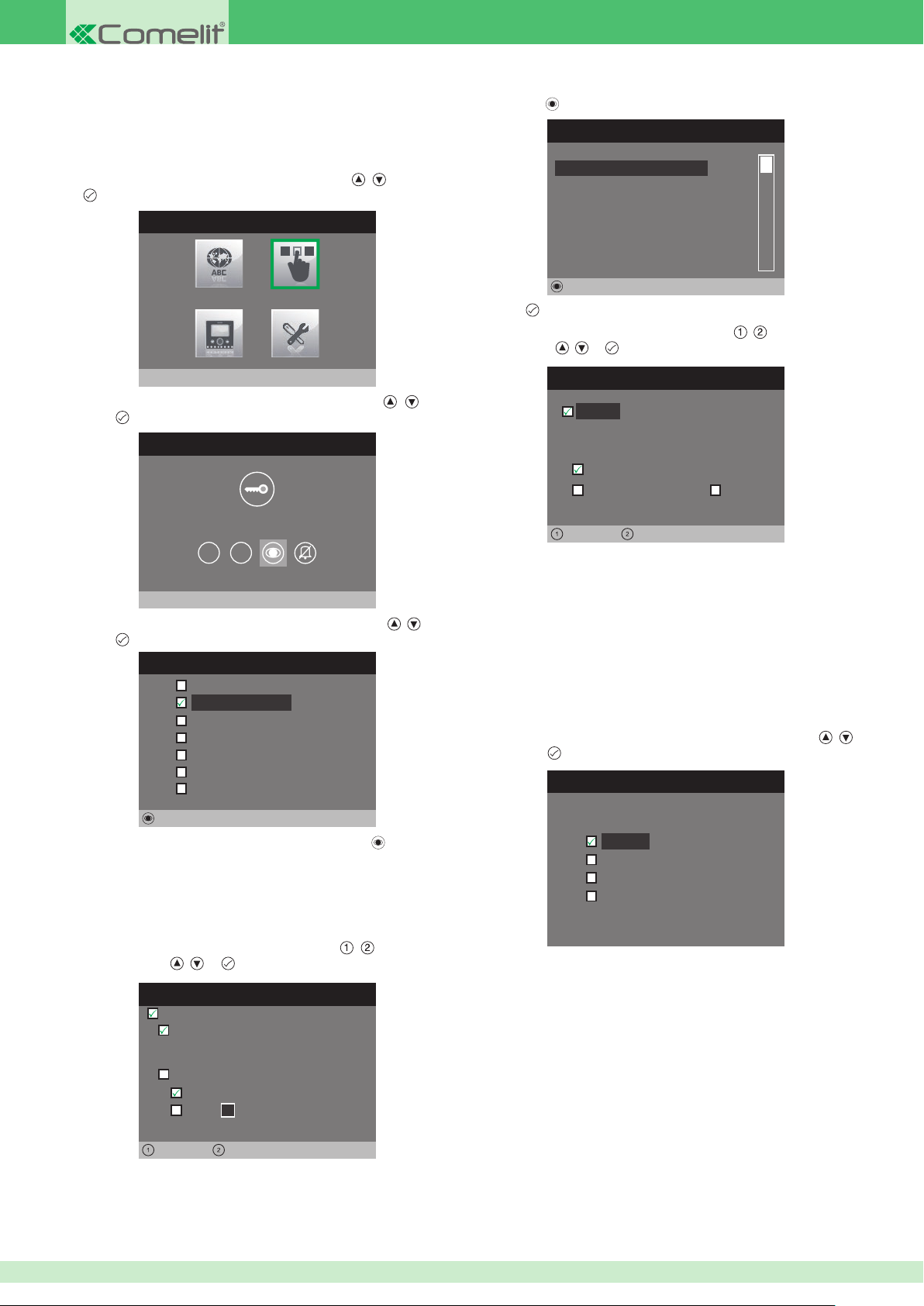
• Con guring 1 - 2 or Self-ignition buttons
1 - 2 and Self-ignition buttons are programmed in the same way and
can perform the same functions. The programming procedure, which
applies to all 3 buttons, is described below.
1. Access the installer menu.
2. Select the Con gure buttons menu by pressing
to access it.
INSTALLER MENU
, and press
If the Self-ignition function is selected:
1. Press the button.
CONFIGURE SELF-IGNITION
Not assigned
Not assigned
Not assigned
Not assigned
Not assigned
Not assigned
Edit
2. Press
3. Select the elds which can be changed using , and change the
to activate the function.
value using , or .
Configure buttons
3. Select the Con gure Self-Ignition menu by pressing , and
press to access it.
BUTTON PROGRAMMING MENU
1 2
Configure Self-Ignition
4. Select the function you wish to assign to the button using , and
to con rm.
press
CONFIGURE SELF IGNITION
Intercom
Self-ignition
Alarms
Lock-release
Actuator
Activate output
Function disabled
Edit
5. Once the desired function has been selected, press
the settings.
to change
CONFIGURE SELF-IGNITION
Active:
ViP address
0 0 0 0 0 0 0 0
Automatic camera
Camera number
Left Right
• The VIP address function determines the address of the external
unit or remote camera module Art. 1445.
• Select the Automatic camera function to link the camera for external
unit Art. 4662C.
• Select the Camera number function and enter the input number
from the 4 available when using a remote camera module Art. 1445.
If the Alarm function is selected:
If you press the button a priority call will be sent to the con gured VIP
address.
1. Select the type of call you wish to assign to the button using
and press
to con rm.
Alarms
1
,
Alarm
Panic
Fire
Priority call 4
If the Intercom function is selected:
Select the elds which can be changed using , and change
the value using , or .
CONFIGURE VIP ADDRESS
Active:
ViP address:
0 0 0 0 0 1 0 1
Backplate:
Master
1
Slave
Left Right
• The VIP address function determines the address of the internal unit
to be called once the button is pressed.
• The Backplate function determines whether to call the main or
secondary internal unit with the same VIP address.
52
For call con guration, see page 54.
Page 53
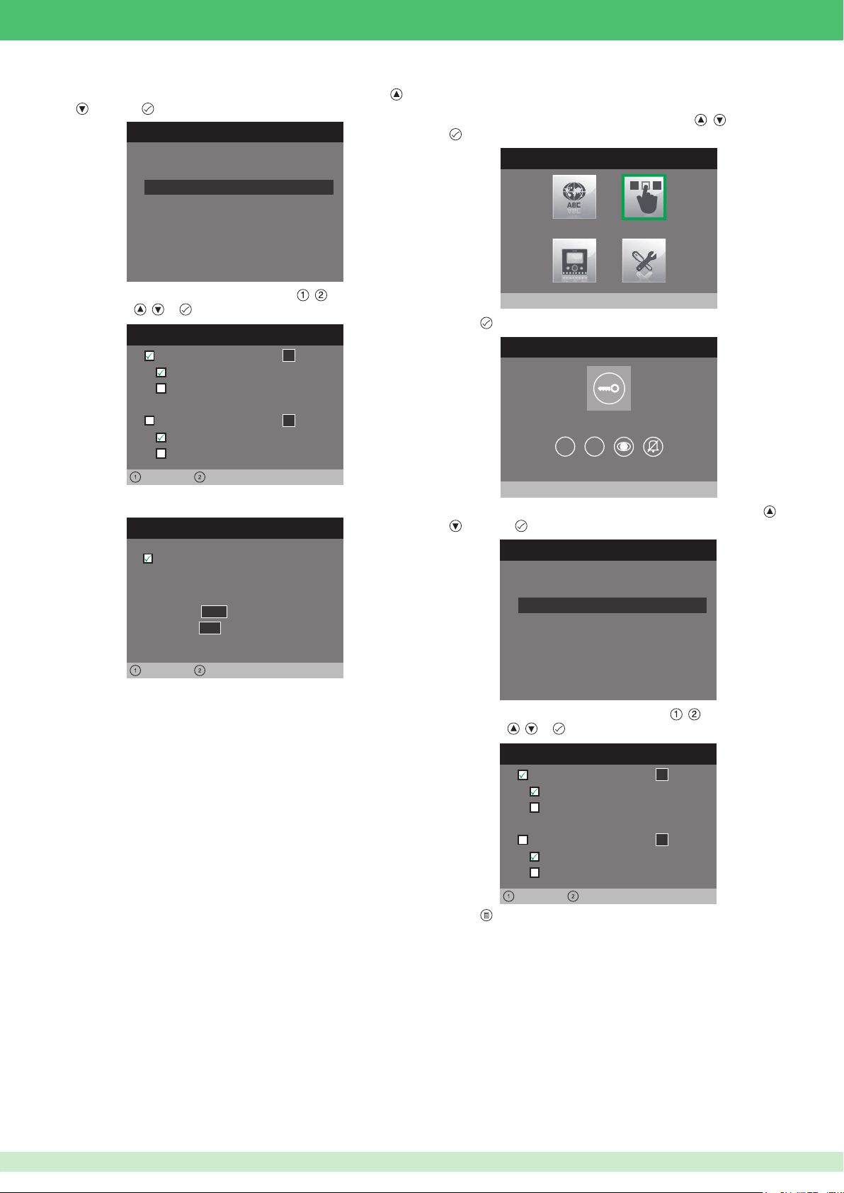
If the Lock-release function is selected:
CONFIGURE BUTTONS
Configure key button
ACTUATOR SETTING
Left Right
1. Select the mode for which you wish to change the function using
and press to con rm.
CONFIGURE RELAY
Configuration during call
Configuration at rest time
• Con guring the key button
,
1. Access the installer menu.
2. Select the Con gure buttons menu by pressing , and press
to access it.
INSTALLER MENU
2. Select the elds which can be changed using , and change the
value using , or .
RELAY DURING CALL
Relay
Active:
1
Interlocutor
Door 0 0 0 0 0 0 0 0
Active:
Relay
1
Interlocutor
Door 0 0 0 0 0 0 0 0
Left Right
If the Actuator function is selected:
Active:
ViP address:
0 0 0 0 0 1 0 1
Module
Output
• The VIP address eld identi es actuator module Art. 1443.
• In the Module eld, select whether to activate the relays on board
the module (255) or those on the expansion module Art. SK9071
connected to it (1 to 10).
• In the Output eld, select the relay you intend to activate. 1 or 2 if
you enter 255 in the module eld. 1 to 10 if you enter an expansion
module in the module eld.
If the Activate Output function is selected:
The button will control an NC/NO output which can be programmed as
monostable or bistable.
For output con guration, see page 56.
255
0 1
Configure buttons
3. Press
to access it.
1 2
4. Select the mode for which you wish to change the function using ,
and press to con rm.
CONFIGURE RELAY
Configuration during call
Configuration at rest time
5. Select the elds which can be changed using , and change the
value using , or .
RELAY DURING CALL
Relay
Relay
1
1
Active:
Interlocutor
Door 0 0 0 0 0 0 0 0
Active:
Interlocutor
Door 0 0 0 0 0 0 0 0
Left Right
6. Press to exit and save the changes.
53
Page 54
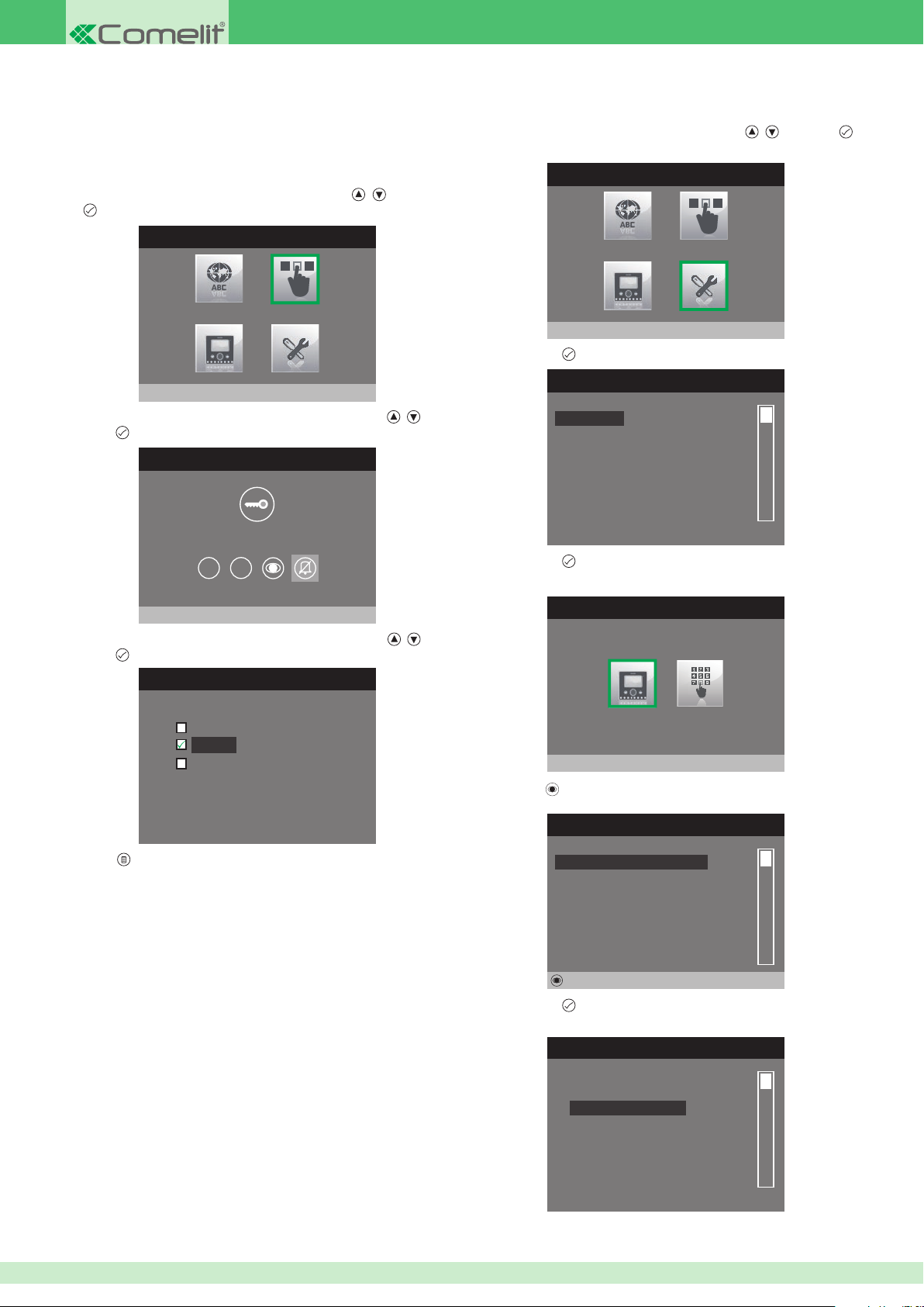
• Con guring the Privacy / Doctor button
Configure Privacy/Doctor
The Privacy function disables the ringtone for calls from the external unit
and intercom. The Doctor function, as well as disabling the door-entry phone
ringtone in the same way as the Privacy function, also enables automatic
activation of the lock-release in response to a call from the external unit.
1. Access the installer menu.
2. Select the Con gure buttons menu by pressing , and press
to access it.
INSTALLER MENU
Configure buttons
• Con guring the intercom directory
1. Access the installer menu.
2. Select the Special Settings menu by pressing
to access it.
INSTALLER MENU
Special Settings
3. Press button to access the Call menu.
SPECIAL SETTINGS MENU
, and press
3. Select the Con gure Privacy/Doctor menu by pressing
press to access it.
CONFIGURE BUTTONS
, and
1 2
4. Select the function you wish to assign to the button using , and
press to con rm.
CONFIGURE PRIVACY / DOCTOR
Doctor mode
Privacy
Doctor + privacy mode
5. Press to exit and save the changes.
Call
Self-ignition
Door open
Alarms
Set ringtone repetition
Set call times
4. Press button to access the Intercom Directory menu.
CALL
Intercom Directory
5. Press the button.
INTERCOM CALLS DIRECTORY
Not assigned
Not assigned
Not assigned
Not assigned
Not assigned
Not assigned
54
Edit
6. Press button to access the Con gure name menu.
CONFIGURE DIRECTORY
Configure name
Configure ViP address
Page 55
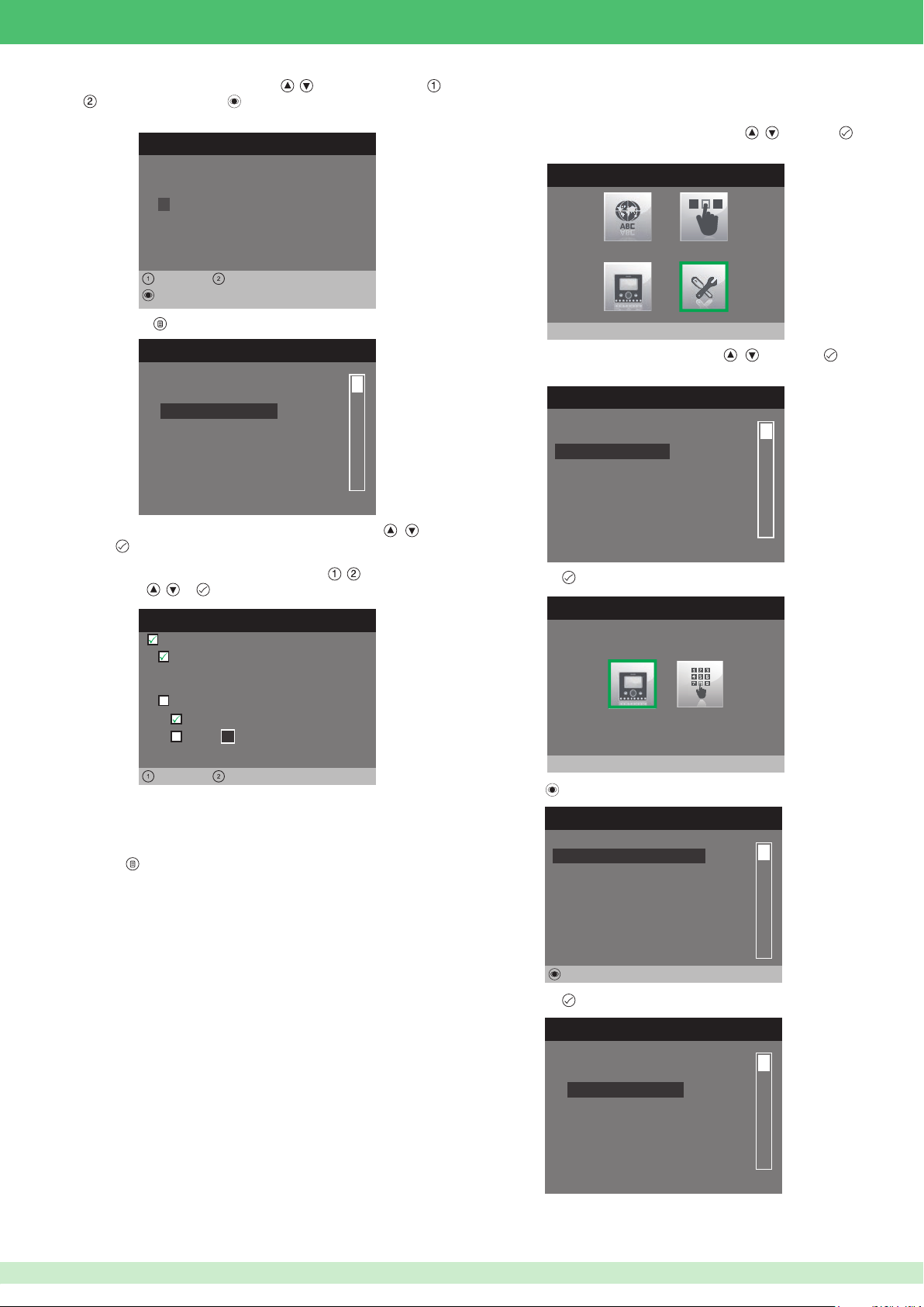
7. Enter the desired name using buttons , to change the letters, ,
CAMERA DIRECTORY
Edit
to move right or left and to delete.
EDIT ENTRY
Configure Name
SMITH
Left Right
Edit
• Con guring the self-ignition directory
1. Access the installer menu.
2. Select the Special Settings menu by pressing
to access it.
INSTALLER MENU
, and press
8. Press button to return to the previous menu.
CONFIGURE DIRECTORY
Configure name
Configure ViP address
9. Select the Con gure VIP address menu by pressing , and
to access it.
press
10. Select the elds which can be changed using , and change the
value using
• The VIP address function determines the address of the internal unit
to be called once the button is pressed.
• The Backplate function determines whether to call the main or
secondary internal unit with the same VIP address.
11. Press
, or .
CONFIGURE VIP ADDRESS
Active:
ViP address:
0 0 0 0 0 1 0 1
Backplate:
Master
1
Slave
Left Right
to exit and save the changes.
Special Settings
3. Select the Self-ignition menu by pressing , and press to
access it.
SPECIAL SETTINGS MENU
Call
Self-ignition
Door open
Alarms
Set ringtone repetition
Set call times
4. Press button to access the Camera directory menu.
SELF-IGNITION
Camera directory
5. Press the button.
Not assigned
Not assigned
Not assigned
Not assigned
Not assigned
Not assigned
6. Press button to access the Con gure name menu.
CONFIGURE DIRECTORY
Configure name
Configure ViP address
55
Page 56
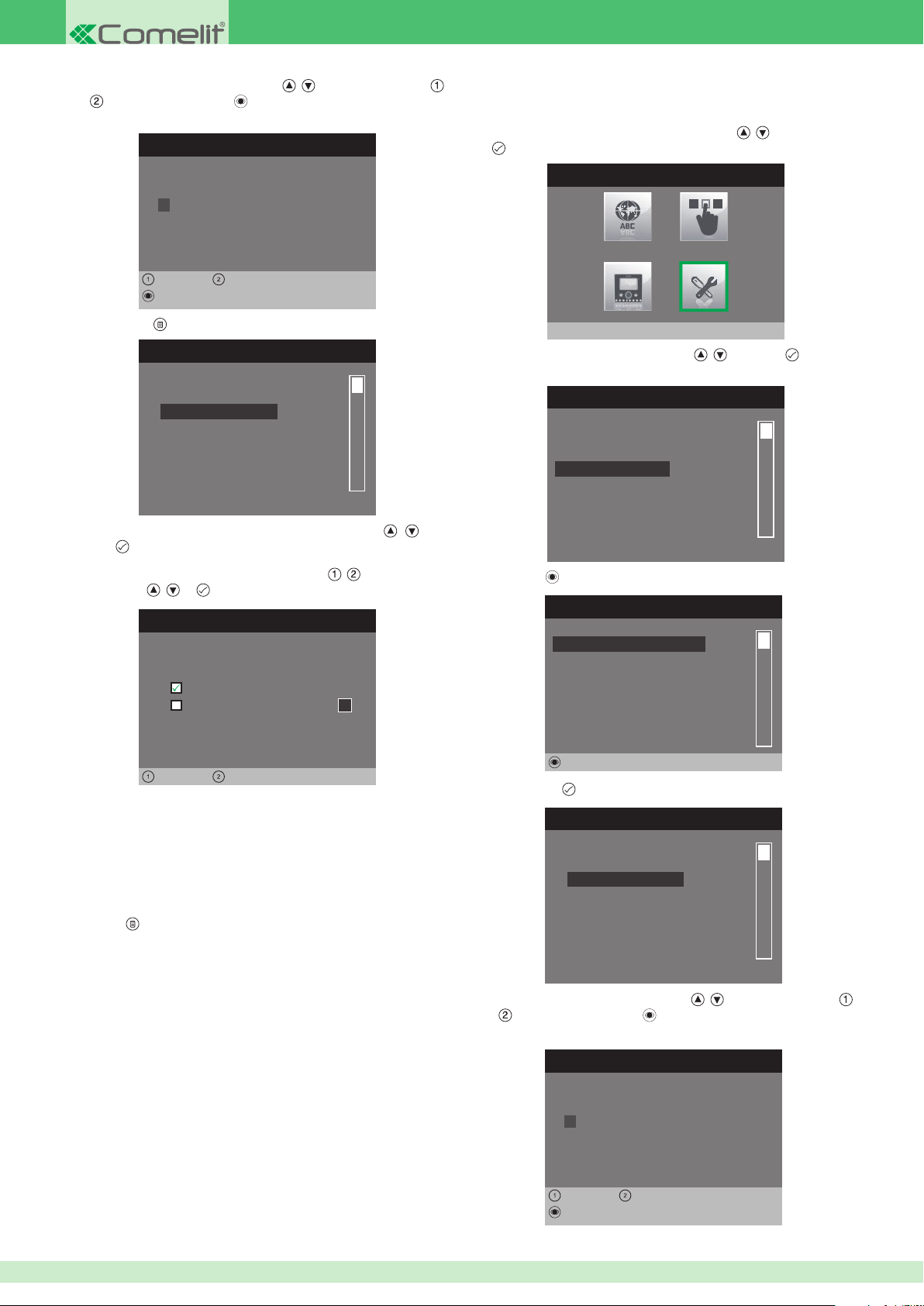
7. Enter the desired name using buttons , to change the letters,
, to move right or left and to delete.
EDIT ENTRY
Configure Name
SMITH
Left Right
Edit
• Con guring the Actuator Directory
1. Access the installer menu.
2. Select the Special Settings menu by pressing
to access it.
INSTALLER MENU
, and press
8. Press button to return to the previous menu.
CONFIGURE DIRECTORY
Configure name
Configure ViP address
9. Select the Con gure VIP address menu by pressing
to access it.
press
10. Select the elds which can be changed using
value using , or .
CONFIGURE VIP ADDRESS
ViP address:
0 0 0 0 0 1 0 1
Automatic camera
Camera number
Left Right
• The VIP address functions determines the address of external unit
Art. 4662C or remote camera module Art. 1445.
• Select the Automatic camera function to link the camera for external
unit Art. 4662C.
• Select the Camera number function and enter the input number
from the 4 available when using a remote camera module Art. 1445.
, and change the
1
, and
Special Settings
3. Select the Actuator menu by pressing , and press to access
it.
SPECIAL SETTINGS MENU
Call
Self-ignition
Actuator
Door open
Alarms
Set ringtone repetition
4. Press the button.
ACTUATOR DIRECTORY
Not assigned
Not assigned
Not assigned
Not assigned
Not assigned
Not assigned
Edit
5. Press button
to access the Con gure name menu.
CONFIGURE DIRECTORY
Configure name
Configure ViP address
11. Press
56
to exit and save the changes.
6. Enter the desired name using buttons , to change the letters,
, to move right or left and to delete.
EDIT ENTRY
Configure Name
South gate
Left Right
Edit
Page 57
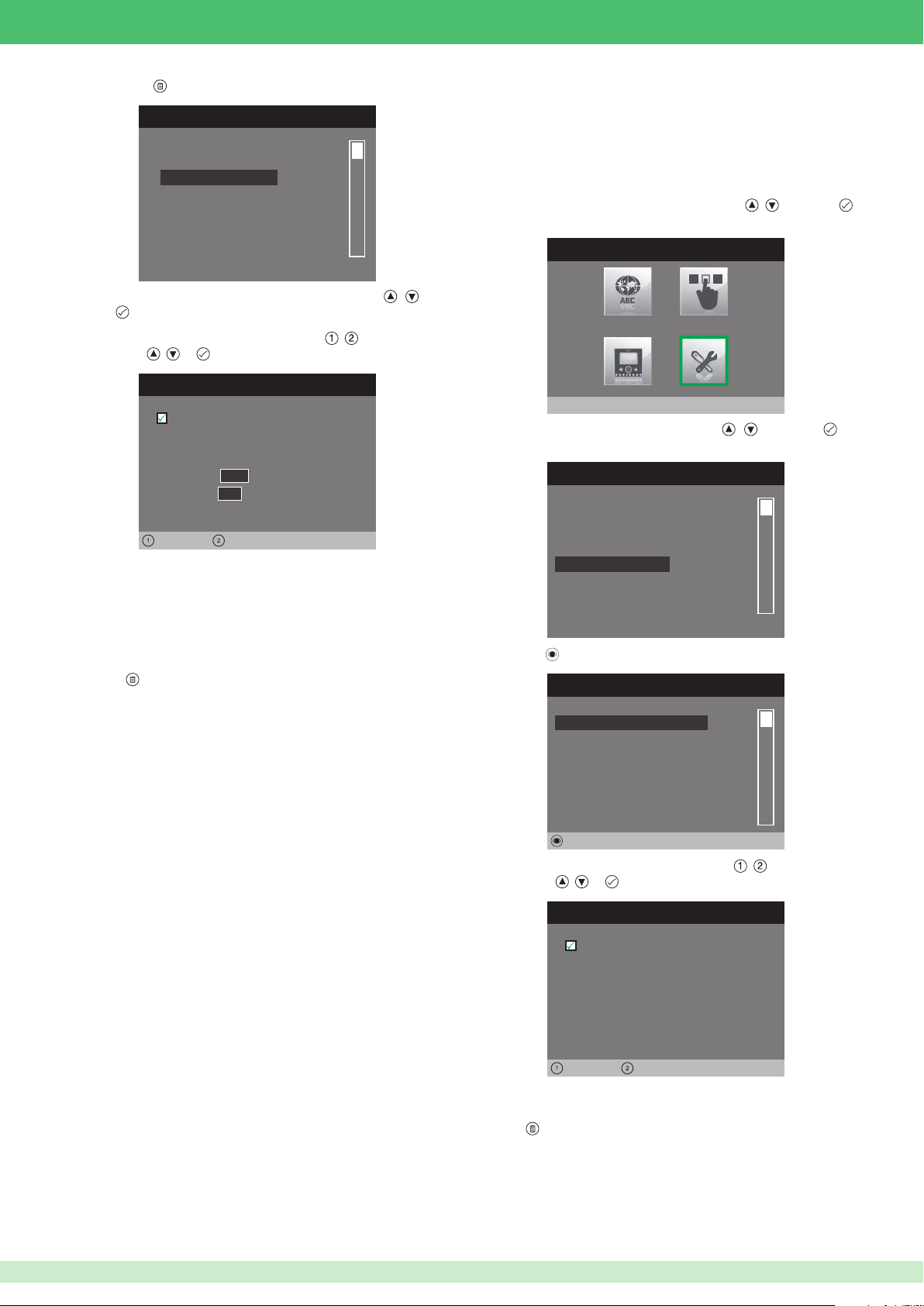
ACTUATOR SETTING
Left Right
7. Press button
DOOR OPEN
Edit
to return to the previous menu.
CONFIGURE DIRECTORY
Configure name
Configure ViP address
8. Select the Con gure VIP address menu by pressing , and
press to access it.
9. Select the elds which can be changed using , and change the
value using , or .
• Setting the Door Open function
The function can be used to monitor the input of an external unit
programmed with the Door Open function. When the input is opened
or closed the key LED on the monitor lights up to indicate that the door
is open.
1. Access the installer menu.
2. Select the Special Settings menu by pressing
to access it.
INSTALLER MENU
, and press
Active:
ViP address:
0 0 0 0 0 1 0 1
Module
Output
• The VIP address eld identi es actuator module Art. 1443.
• In the Module eld, select whether to activate the relays on board
the module (255) or those on the expansion module Art. SK9071
connected to it (1 to 10).
•
In the Output eld, select the relay you intend to activate: 1 or 2 if
you enter 255 in the module eld, or 1 to 10 if you enter an expansion
module in the module eld.
10. Press to exit and save the changes.
255
0 1
Special Settings
3. Select the Door open menu by pressing , and press to
access it.
SPECIAL SETTINGS MENU
Call
Self-ignition
Actuator
Door open
Alarms
Set ringtone repetition
4. Press the button.
Not assigned
Not assigned
Not assigned
Not assigned
Not assigned
Not assigned
5. Select the elds which can be changed using , and change the
value using
• The VIP address eld identi es the external unit you wish to
monitor.
6. Press to exit and save the changes.
, or .
CONFIGURE VIP ADDRESS
Active:
ViP address:
0 0 0 0 0 1 0 1
Left Right
57
Page 58
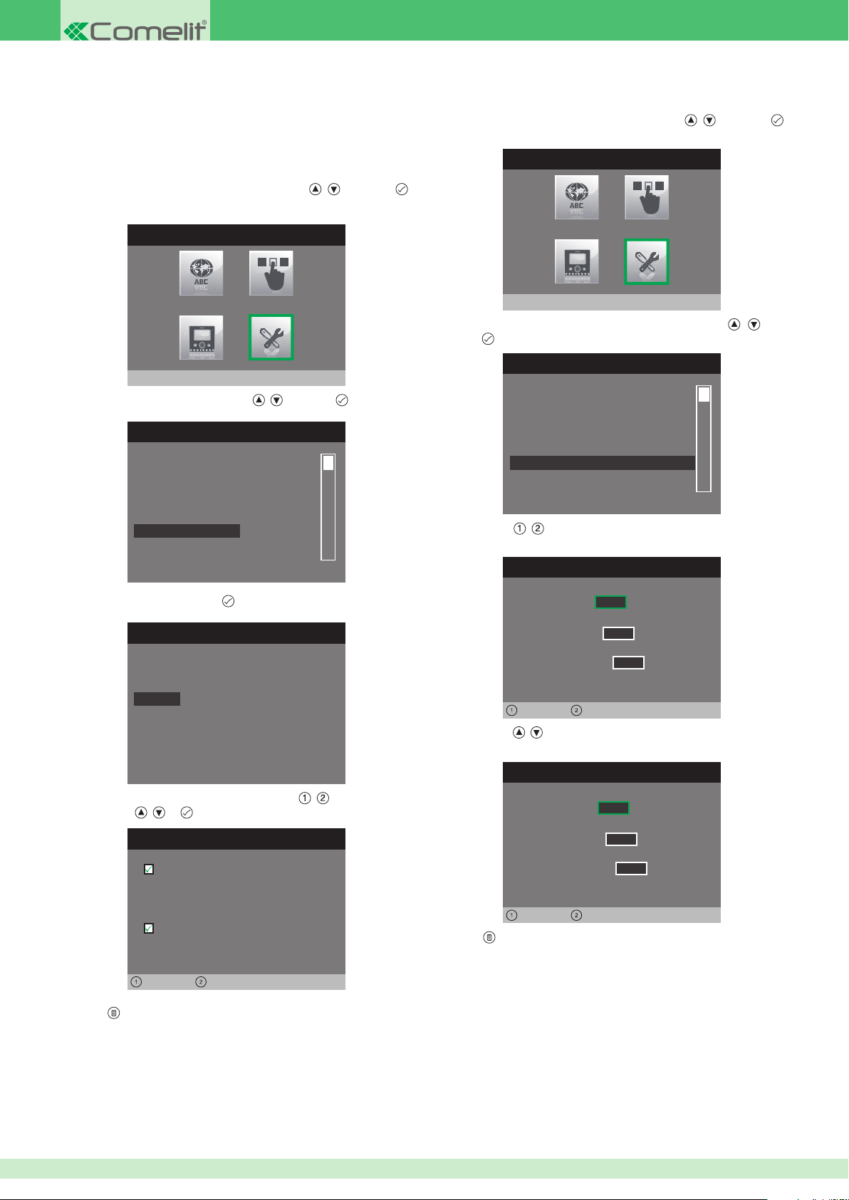
SET RINGTONE REPETITION
Left Right
Left Right
This menu can be used to set the VIP address which will be contacted
when a priority call is sent. The procedure applies for all 4 call types; the
example below illustrates a Panic priority call.
1. Access the installer menu.
• Setting the ringtone repetition• Setting the Alarm function
1. Access the installer menu.
2. Select the Special Settings menu by pressing
to access it.
INSTALLER MENU
, and press
2. Select the Special Settings menu by pressing
to access it.
INSTALLER MENU
Special Settings
3. Select the Alarms menu by pressing , and press to access it.
SPECIAL SETTINGS MENU
, and press
Call
Self-ignition
Actuator
Door open
Alarms
Set ringtone repetition
4. Select the call type and press .
Special Settings
3. Select the Set ringtone repetition menu by pressing , and
press to access it.
SPECIAL SETTINGS MENU
Call
Self-ignition
Door open
Alarms
Set ringtone repetition
Set call times
4. Use buttons , to select for which type of call you wish to set the
function.
External call
0 0 1
Alarms
Alarm
Panic
Fire
Priority call 4
5. Select the elds which can be changed using , and change the
value using
6. Press to exit and save the changes.
, or .
CONFIGURE ALARMS
Active:
ViP address:
0 0 0 0 0 2 0 0
Audio message
Left Right
Intercom call
Floor door call
5. Use buttons
the type of call selected.
, to change the number of repetitions as desired for
SET RINGTONE REPETITION
External call
Intercom call
Floor door call
6. Press to exit and save the changes.
0 0 1
0 0 1
0 0 3
0 0 1
0 0 1
58
Page 59
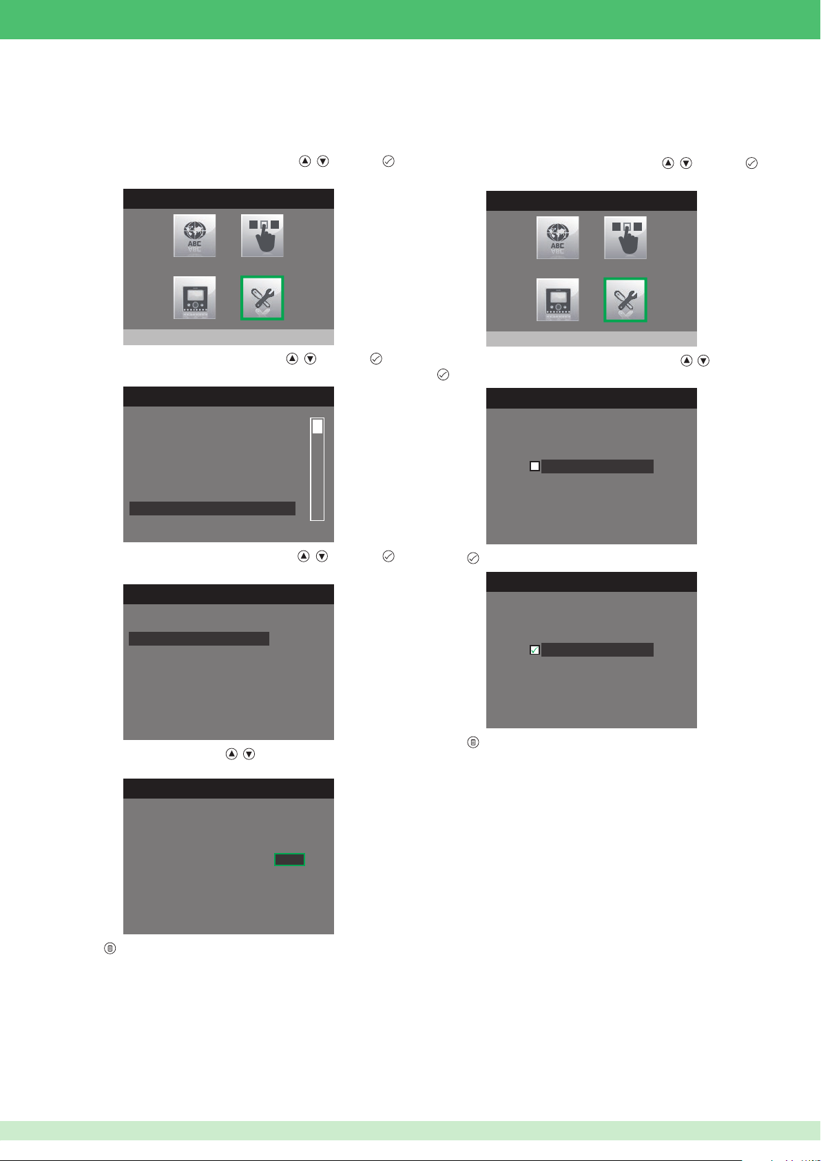
• Setting call times
Within this menu, the time can be set for various functions. The Reply
wait time setting is shown below, as an example which also applies for
the other functions.
1. Access the installer menu.
2. Select the Special Settings menu by pressing
to access it.
INSTALLER MENU
, and press
• Setting automatic answer
If the Automatic answer function is enabled, the audio will be activated
automatically on receipt of a call from the external unit, internal unit or
switchboard.
1. Access the installer menu.
2. Select the Special Settings menu by pressing
to access it.
INSTALLER MENU
, and press
Special Settings
3. Select the Set call times menu by pressing , and press to
access it.
SPECIAL SETTINGS MENU
Call
Self-ignition
Door open
Alarms
Set ringtone repetition
Set call times
4. Select the Reply wait time menu by pressing , and press
to access it.
SET CALL TIMES
Reply wait time
Talk time
Intercom talk time
Reset wait time
Special Settings
3. Select the Set automatic answer menu by pressing , and press
to access it.
SET AUTOMATIC ANSWER
Automatic answer
4. Press
to enable it.
SET AUTOMATIC ANSWER
Automatic answer
5. Change the value using buttons
SET REPLY WAIT TIME
Reply wait time
6. Press to exit and save the changes.
•
Reply wait time: this is the time for which a call from the external or internal unit
remains active and waiting for the user to answer.
• Talk time: this is the time for which the audio remains active, once a call from
the external unit has been accepted.
• Intercom talk time: this is the time for which the audio remains active, once a
call from an internal unit or from the switchboard has been accepted.
• Reset wait time: this is the time for which the audio remains active once a
call has ended. The conversation can be resumed if the audio button is pressed
again within the set time period.
, .
0 6 0
5. Press
to exit and save the changes.
59
Page 60
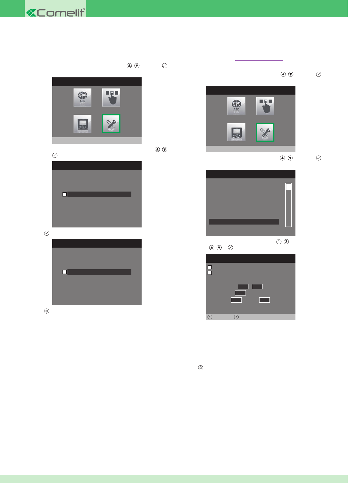
Activate output
Left Right
• Video memory records always
If activated, this function can be used to record images and audio (10
sec.) from the external unit, even if the call is answered.
1. Access the installer menu.
2. Select the Special Settings menu by pressing
to access it.
INSTALLER MENU
Special Settings
3. Select the Video memory records always menu by pressing ,
and press
to access it.
VIDEO MESSAGE RECORDING
, and press
• Activate output
Planux monitors are equipped with an NC/NO output which can be
programmed as monostable or bistable. This output can be controlled
by one of the buttons on board the monitor, or by one of the inputs if
suitably con gured with the Activate output function.
1. Access the installer menu.
2. Select the Special Settings menu by pressing
to access it.
INSTALLER MENU
Special Settings
3. Select the Activate output menu by pressing , and press
to access it.
SPECIAL SETTINGS MENU
, and press
Video mem. records always
4. Press to enable it.
VIDEO MESSAGE RECORDING
Video mem. records always
5. Press to exit and save the changes.
Alarms
Set ringtone repetition
Set call times
Set automatic answer
Video mem. records always
Activate output
4. Select the elds which can be changed using , and change the
value using
• The output is set as Normally open by default; tick the box next to
Normally open to change this setting to Normally closed.
• The output is set as Monostable by default; tick the box next to
Monostable to change this setting to Bistable.
•
Fill in the Activation period elds for Monostabile mode.
, or .
Normally open
Monostable
Activation period
Seconds
Minutes
Hours
0 5,0 0
0 0
0 0 0 0
Days
60
5. Press to exit and save the changes.
Page 61
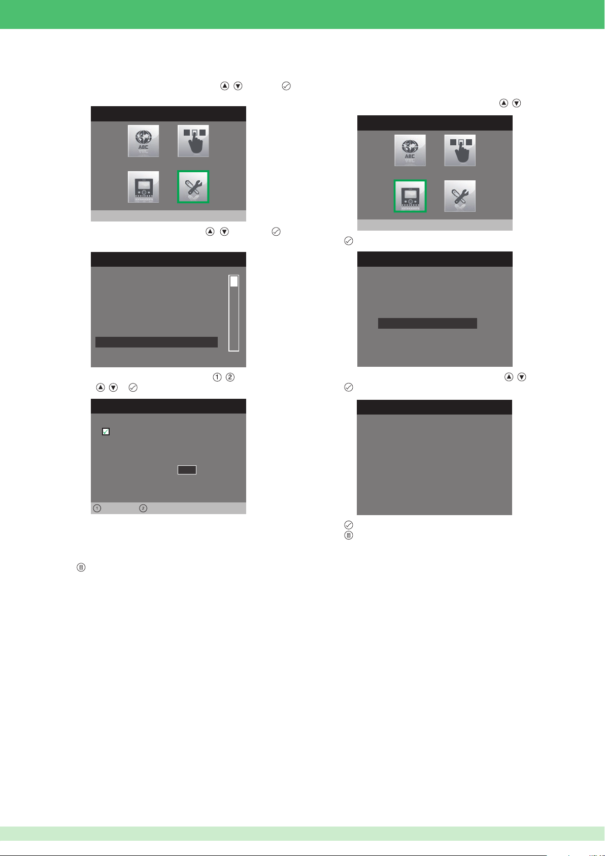
• Call divert
1. Access the installer menu.
2. Select the Special Settings menu by pressing
to access it.
INSTALLER MENU
, and press
• Reset con guration
This function can be used to restore the factory set values of the monitor,
deleting all con gurations applied in the meantime.
1. Access the installer menu.
2. Select the Con gure monitor menu using buttons
INSTALLER MENU
, .
Special Settings
3. Select the Call divert menu by pressing , and press to
access it.
SPECIAL SETTINGS MENU
Set ringtone repetition
Set call times
Set automatic answer
Video mem. records always
Activate output
Call divert
4. Select the elds which can be changed using , and change the
value using , or .
Call divert
Active:
ViP address:
0 0 0 0 0 1 0 1
Wait time
Left Right
• The VIP address eld identi es the internal unit or CPS to which
you want to divert the call.
• The Wait time eld identi es the wait time before the call is diverted.
1 0
Configure monitor
3. Press
to access it.
CONFIGURE MONITOR
ViP address
About
Reset configuration
4. Select the Reset con guration menu using buttons
5. Press to access it.
RESET CONFIGURATION
Continue?
6. Press to con rm.
7. Press to cancel.
, .
5. Press to exit and save the changes.
61
Page 62
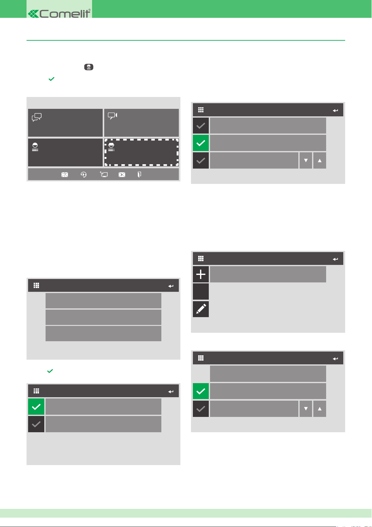
7Stelle monitor Art. 6501
• Accessing the installer menu
1. Press PROGRAMMER to access the INSTALLER MENU.
2. Enter the password.
3. Press to conrm the password and access the INSTALLER
MENU.
Sat 15/06/13 01:21
INTERCOM CAMERAS
PROGRAMMERUSER
The password for the installer menu is 0000. To change the
password, please refer to the technical manual for VIP Manager
Art. 1449.
• Conguring buttons
The buttons on the Sette Stelle internal unit Art. 6501 can be programmed
with various functions.
The procedure to be used for all buttons is detailed below.
1. Access the Installer menu.
2. Access the Congure buttons menu.
• Conguring functions
Press the name of the function to access the corresponding conguration
menu.
◊ Intercom function
This function can be used to send an intercom call to a specic device.
INTERCOM
Configure ViP address
Master
Slave
1. Access the Congure VIP address menu to set the address of the
device you want to associate with the intercom function.
2. Select whether to call the Master or Slave backplate for the set
address. If you select Slave, you will also need to set the exact
number of the slave as desired.
◊ Self-ignition function
This function can be used to view the images transmitted by the camera
for one or more devices connected to the system.
SELF-IGNITION
00002003
1
INSTALLER MENU
Configure buttons
Configure monitor
Special Settings
3. Select the button you wish to congure.
4. Press next to the function you want to assign to the button.
KEY BUTTON
Lock-release
Actuator
C
1. Press the + icon to add a device to be assigned to the function
SELF-IGNITION
Configure ViP address
Automatic camera
Camera number
2. Access the Congure VIP address menu to set the address of the
device you want to associate with the self-ignition function.
3. Select which device camera you wish to use, from Automatic (in the
case of external units or camera number one of modules Art. 1445)
or Camera number (if you want to use the camera of a device
Art. 1445).
4. To remove a device from the list, press icon C followed by the device.
5. To edit the settings of a device on the list, press the pencil icon
followed by the device.
1
62
Page 63
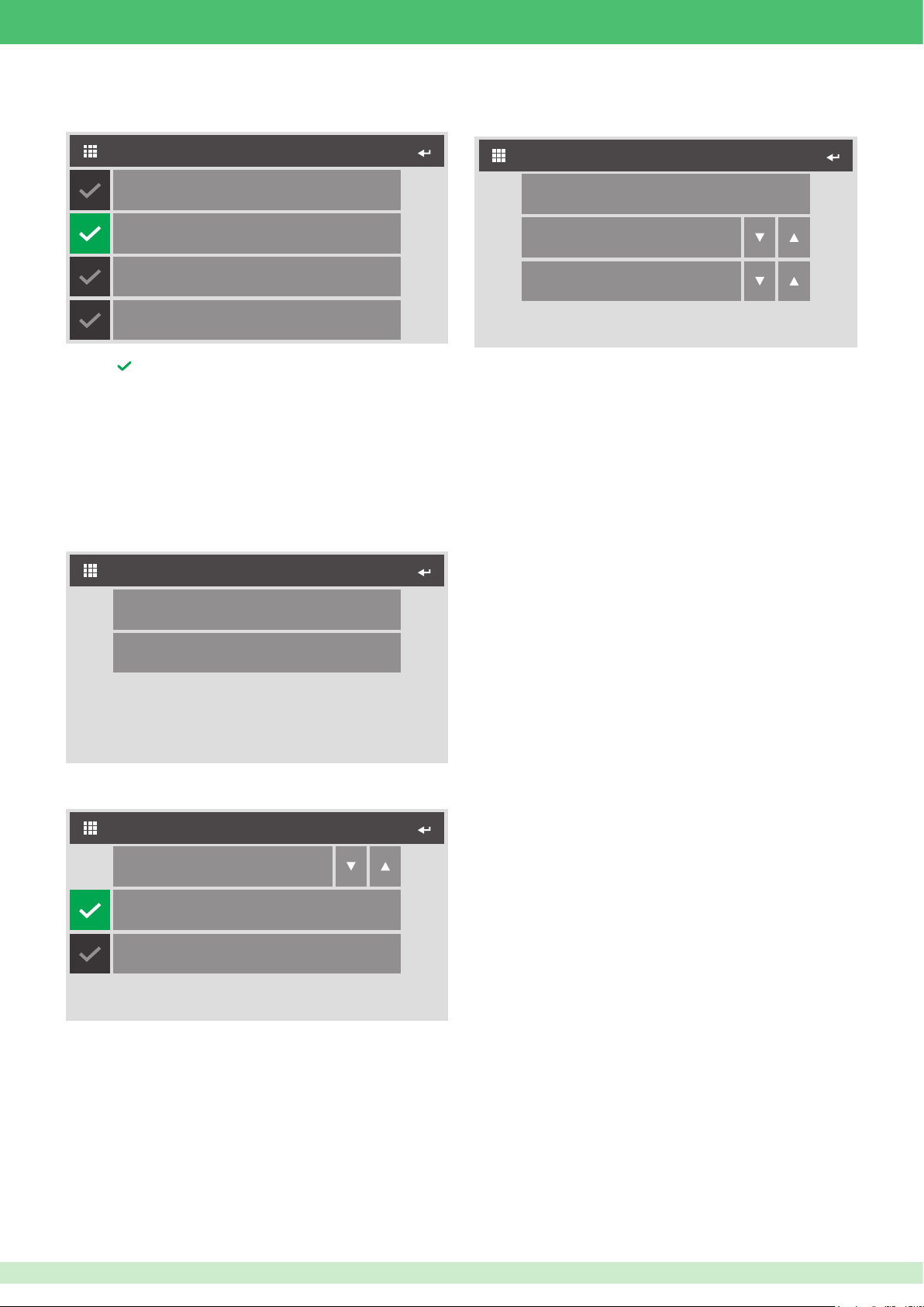
◊ Alarm function
This function can be used to link an alarm call to the button.
◊ Actuator function
This function is used to activate the relay output of an IO actuator
module or that of an expansion device connected to it.
ALARMS
Alarm
Panic
Fire
Priority call 4
1. Press next to the call you want to assign to the button.
For priority call conguration, see page 62.
◊ Lock-release function
This function has two statuses:
◊
Lock-release during call: it will perform one or two actions when a
call with the external unit is in progress
◊
Lock-release at rest time: it will perform one or two actions when
there are no calls in progress
CONFIGURE LOCK-RELEASE
ACTUATOR
Configure ViP address
Module
Output
1
1
1. Access the Congure VIP address menu to set the address of the
IO device you want to associate with the actuator function.
2. Select whether to associate one of the expansion modules (1 to 10)
or to directly associate one of the two IO module relay outputs (255).
3. Select which output to use (1 to 10 for expansion modules and 1 or
2 for IO module).
◊ Activate output function
This function can be used to activate the internal unit NC/NO output by
pressing the button.
For output conguration, see page 62.
Configuration during call
Configuration at rest time
1. Select which status you wish to congure.
2. Select which action you wish to congure.
CONFIGURE LOCK-RELEASE
Relay
Interlocutor
External unit
1
3. Select which relay you wish to activate.
4. Select whether to interact with the relay of the external unit making
the call or a different one. If you select External unit you will need to
congure its VIP address.
63
Page 64
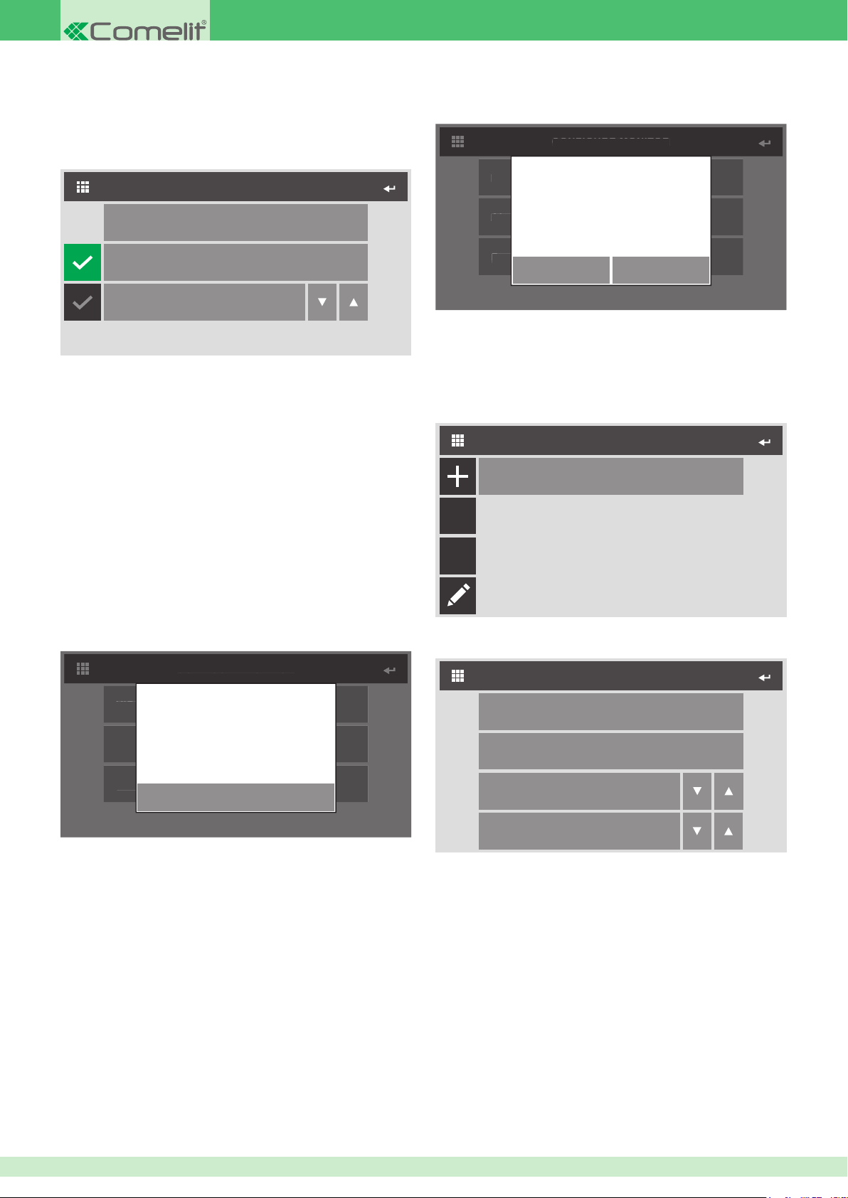
• Con guring the monitor
About
ViP address
About
ViP address
◊ VIP address
This menu can be used to con gure the VIP address of the internal unit.
◊ Reset con guration
This function can be used to restore the factory set values of the monitor,
deleting all con gurations applied in the meantime.
CONFIGURE MONITOR
CONFIGURE MONITOR
Configure ViP address
Master
Slave
1
1. Access the Con gure VIP address menu to set the address of the
device.
2. Select whether to set the device as Master or Slave. If you select
Slave, you will also need to set the exact number.
Master
By Master we mean the main internal unit in an apartment. Every
Master internal unit in the system must have a different VIP code. The
Master internal unit manages all external unit / switchboard / intercom
calls. It is essential that, in an apartment, one of the internal units is set
as a Master.
Slave
By Slave we mean one or more secondary internal units (MAX. 15) in
an apartment. Each Slave has the same VIP address as the Master
internal unit.
ViP address
About
Reset configuration
CONFIRM
Continue?
CANCEL
• Special Settings
◊ Actuator Directory
This menu can be used to manage the directory of actuators connected
to the system.
ACTUATOR DIRECTORY
Actuator 1
Abc
C
◊ About
This menu can be used to view system data.
CONFIGURE MONITOR
ViP address
About
Reset configuration
MAC: 00:25:34:08:00:DC
IP: 169.254.241.41 (A/16)
GW: 0.0.0.0
ID: 00000001, SUB: 0
SW: 1.5.3
OK
1. Access the Actuator setting menu by pressing the + icon to add a
new device to the directory.
ACTUATOR SETTING
Configure Name
Configure ViP Address
Module
Output
255
1
2. Access the Con gure Name menu to associate the actuator with the
name which will appear in the directory.
3. Access the Con gure VIP address menu to enter the address of the
actuator module Art. 1443.
4. In the module eld, select whether to control the relay on board the
module itself (255) or one on board an expansion module connected
to it (1 to 10).
5. In the output eld, select the exact relay you wish to control. 1 or 2
for relays on board the module art.1443, or 1 to 10 for relays of an
expansion module connected to it.
64
Page 65
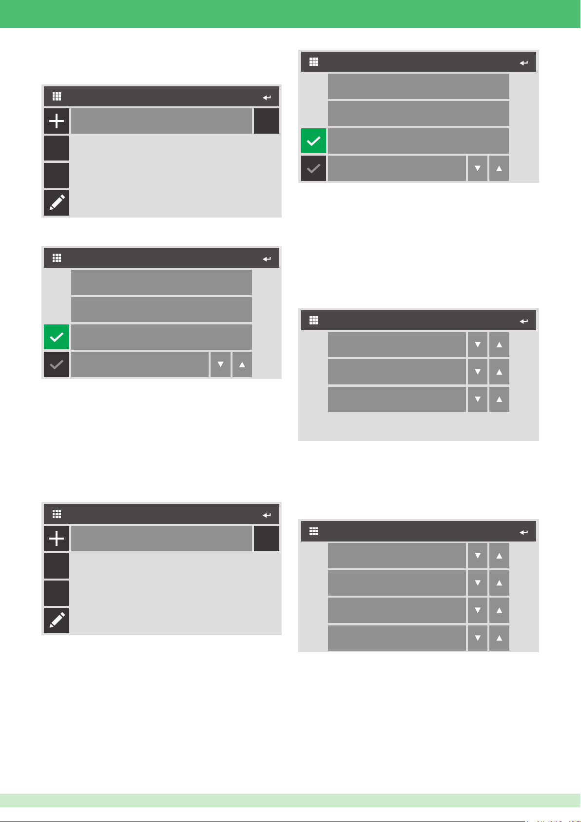
◊ Camera Directory
This menu can be used to manage the directory of cameras connected
to the system.
CAMERAS DIRECTORY
CONFIGURE INTERCOM
Configure Name
CAMERA 1
123
Abc
C
1. Access the Congure camera menu by pressing the + icon to add a
new device to the directory.
CONFIGURE CAMERA
Configure Name
Configure ViP Address
Automatic camera
Camera number
2. Access the Congure Name menu to associate the camera with the
name which will appear in the directory.
3. Access the Congure VIP address menu to enter the address of the
cameras module Art. 1445 or the video external unit.
4. Select whether to use the automatic camera (in the case of an
external unit) or indicate the number of the device connected to a
cameras module Art. 1445.
◊ Intercom Directory
This menu can be used to manage the intercom call directory.
INTERCOM CALLS DIRECTORY
1
Configure ViP Address
Master
Slave
2. Access the Congure Name menu to set the name which will appear
in the directory.
3. Access the Congure VIP address menu to enter the address of the
device you want to associate with the call.
4. Select whether to call the Master or Slave device. If you select Slave,
you will also need to set the exact number of the device to call.
1
◊ Set ringtone repetition
This menu can be used to set the number of times the ringtone is
repeated on receipt of a call.
SET RINGTONE REPETITION
External call
Intercom call
Floor door call
1. Select the number of times the ringtone is repeated for each type of
call.
1
1
1
◊ Set call times
This menu can be used to change the various call time values.
SMITH
123
Abc
C
1. Access the Congure intercom menu by pressing the + icon to add
a new entry to the directory.
SET CALL TIMES
Awaiting reply
Conversation
Intercom conversation
Reset wait times
1. Set the duration in seconds for each value.
◊ Awaiting reply:
◊ Conversation:
◊ Intercom conversation:
◊ Reset wait time:
wait time in which, if there is no answer, the call is
ended.
maximum duration of a conversation with an external
unit.
maximum duration of a conversation with an
internal unit.
maximum time in which it is possible to pick up the
audio line if it is cut off.
60
90
90
10
65
Page 66
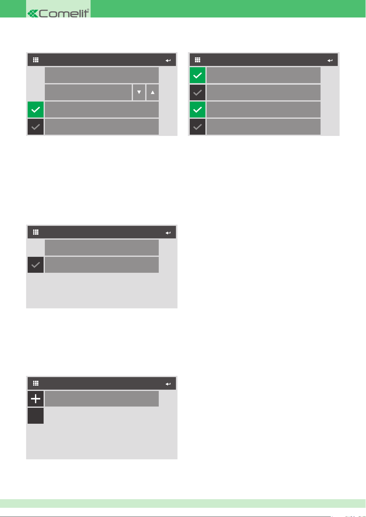
◊ Call divert
This menu can be used to set the call divert function.
◊ Activate output
This menu can be used to set the operating mode of the relay on board
the monitor.
CALL DIVERT
Configure ViP Address
Wait time
Activate timed divert
Activate divert when busy
1. Access the Congure VIP address menu to enter the address of the
device to which the call will be diverted.
2. Set the wait time before the call is diverted.
3. Select whether to divert the call after a set period of time, if the line is
busy or in both cases.
10
◊ Alarms
This menu can be used to set the VIP address of the device which will
be called when a priority call is made. The conguration for Alarm calls
is illustrated below, as an example. The same procedure also applies to
the other 3 priority call types.
ALARMS
ACTIVATE OUTPUT
Normally open
Normally closed
Monostable
Bistable
1. Select whether the output is normally closed or normally open.
2. Select whether the output should be activated in Monostable or
Bistable mode. If you select Monostable mode, you will also need to
set its switching duration time.
◊ Automatic answer
If you activate this option, the monitor will automatically pick up the
audio line on receipt of a call.
◊ Video memory records always
If you activate this option, the monitor will record the video conversation
with the external unit, even if the call is answered.
Configure ViP Address
Audio message
1. Access the Congure VIP address menu to set the address of the
device which will be called when an alarm call is made.
2. Select whether to activate the audio message when the call is sent.
◊ Door open
This menu can be used to set the address of the external units to be
monitored.
DOOR OPEN
00002003
C
1. Access the Address menu by pressing the + icon to add the address
of the door to be monitored.
66
Page 67
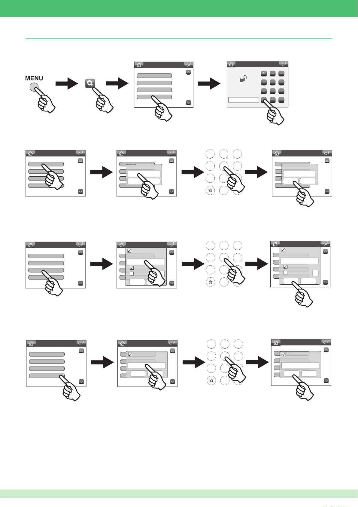
123
123
123
Porter switchboard Art. 1952
• Accessing the installer menu
• Setting the VIP Address
Advanced Settings
ViP address
About
Associated camera
Associated video output
ViP address
About
Associated camera
Associated video output
Door open
Calibration
Short cut keys
Advanced
Advanced Settings
ViP address
Confirm Cancel
Settings menu
ABC DEF
456
456
789
789
0#
PASSWORD:
****
MNOJKLGHI
WXYZTUVPQRS
Enter password
2 3
1
4
8 9
7
0
5 6
C
ViP address
ViP address
About
00000001
Associated camera
Confirm Cancel
Associated video output
Advanced Settings
• Setting the associated camera
This function can be used to associate a camera with the switchboard, via module Art. 1445. The images from this camera will be displayed on the
internal unit monitor during the conversation.
Advanced Settings
ViP address
About
Associated camera
Associated video output
Advanced Settings
Active:
ViP address
Camera ViP address
About
Automatic camera
Associated camera
Camera number
Associated video output
Confirm Cancel
ABC DEF
456
456
789
789
0#
MNOJKLGHI
WXYZTUVPQRS
Advanced Settings
Active:
ViP address
Camera ViP address
00002001
About
Automatic camera
Associated camera
Camera number
Associated video output
Confirm Cancel
• Setting the associated video output
This function should be used in conjunction with the previous function (Associated camera). If the VIP address of an IP/PAL module Art. 1446 on the connected
monitor is set to the same as the latter, the images from the associated camera will be displayed when the switchboard enters conversation mode.
Advanced Settings
ViP address
About
Associated camera
Associated video output
Advanced Settings
ViP address
Active:
Video output ViP address
About
ssociated camera
Confirm Cancel
Associated video output
ABC DEF
456
456
789
789
0#
MNOJKLGHI
WXYZTUVPQRS
Advanced Settings
ViP address
Active:
Video output ViP address
About
00003001
Associated camera
Confirm Cancel
Associated video output
67
Page 68
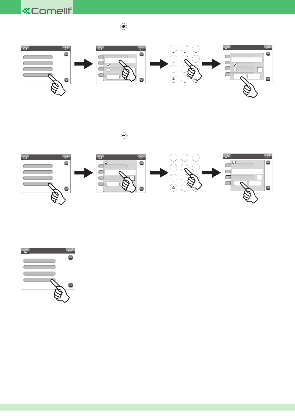
123
• Programming the self-ignition key
123
This function can be used to view the images transmitted by the camera for one or more devices connected to the system.
Advanced Settings
About
Associated camera
Associated output
Self-ignition key
Advanced Settings
Camera ViP address
ViP address
About
Automatic camera
Associated camera
Camera number
Associated video output
Confirm Cancel
ABC DEF
456
456
789
789
0#
MNOJKLGHI
WXYZTUVPQRS
Advanced Settings
Camera ViP address
ViP address
00002001
About
Automatic camera
Associated camera
Camera number
Associated video output
Confirm Cancel
• The VIP address function determines the address of the external unit or remote camera module Art. 1445.
• Select the Automatic camera function to associate the camera for the external unit.
• Select the Camera number function and enter the input number from the 4 available when using a remote camera module Art. 1445.
• Programming the lock-release key
This function can be used to activate a relay for the associated external unit.
Advanced Settings
Associated camera
Associated output
Self-ignition key
Lock-release key
Advanced Settings
Active:
ViP address
Porter Address
About
Associated camera
Relay number
Associated video output
Confirm Cancel
ABC DEF
456
456
1
789
789
MNOJKLGHI
WXYZTUVPQRS
0#
Advanced Settings
Active:
ViP address
Porter Address
About
00002003
Associated camera
Relay number
Associated video output
Confirm Cancel
1
• In the Porter Address eld, enter the VIP address of the external unit you want to associate with the function.
• In the Relay number eld, enter which of the two external unit relays you want to activate.
Activating / deactivating the OFF key
If activated, the OFF key can be used to switch the switchboard on and off.
Advanced Settings
Associated video output
Self-ignition key
Lock-release key
OFF key disabled
68
Page 69
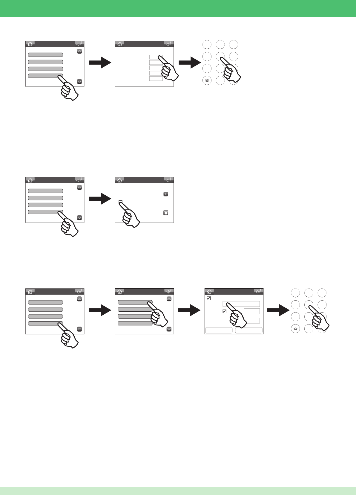
Setting the call times
123
0#
123
0#
Advanced Settings
Lock-release key
OFF key disabled
Call times
Call divert
Set call times
Expressed as min:sec
Awaiting reply (in)
Awaiting ans.serv.act.
Conversation
Pause
Awaiting reply (out)
01:00
00:30
01:30
01:30
00:30
ABC DEF
456
456
789
789
WXYZTUVPQRS
MNOJKLGHI
◊ Awaiting reply (in):
wait time in which a call is ended if it is not answered.
◊ Awaiting ans.serv.act.: maximum time after which the answering service is activated if a call is not answered.
◊ Conversation: maximum conversation duration.
◊ Pause: maximum time a call can be put on hold.
◊ Awaiting reply (out): wait time in which, if there is no answer, the call is ended.
Setting call divert
This function can be used to divert incoming calls to another switchboard on the list.
Advanced Settings
Lock-release key
OFF key disabled
Call times
Call divert
Set call times
2002
Setting activations on call
When this function is active, on receipt of a speci c type of call the switchboard will activate the output of an actuator module Art. 1443, or of an
extension unit connected to it.
The following example illustrates the function con guration procedure for an Alarm call; the same also applies for the other types available in the menu.
Advanced Settings
OFF key disabled
Call times
Call divert
Activations on call
Advanced Settings
Alarm
Panic
Fire
Call priority 4
Active:
Address
Module
Output
Confirm
Advanced Settings
Builtin
Cancel
ABC DEF
456
456
789
789
MNOJKLGHI
WXYZTUVPQRS
In the address eld, enter the VIP address of actuator Art. 1443.
In the module eld, select whether to activate an output on board the actuator Art. 1443 (Builtin), or specify the number of the expansion device with
which you want to interact. In the output eld, enter the exact number of the output you want to activate (1 or 2 for module art.1443, or 1 to 10 for an
expansion device).
69
Page 70
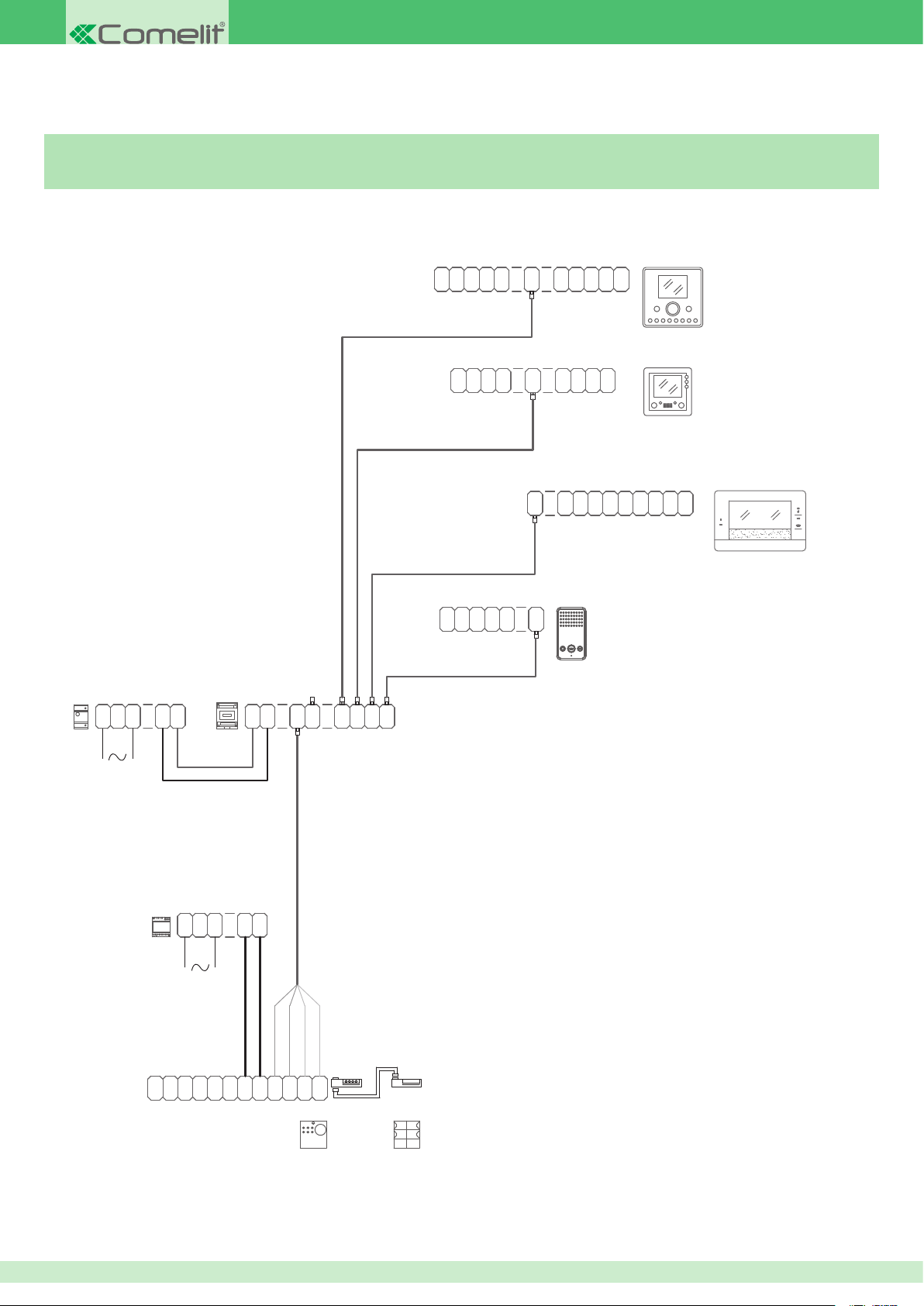
Chapter 6: Wiring diagrams
1441
6202W+
P
C
C
6501
VIP/001
Connecting Powercom call button module Art. 3337/3-4-6
0
V
OUT
G
N
D P
S
0
A
F
N
P
IN
1
1
C
AL
F
N
V
+
1
C
S
0
N
V
+
1
C
N
3
C
SS
N
+
-
1
OP+OP-0
C
F
AL
P
OP+OP
-
OUT
V 1
P
0
A
V
N
C
S
F
+
P
6203W
AL
P
A
N
OUT
0
AL
1V
0
V
6231
6304
1
2
1440
+
L
-
N
V V
IN
+
IN
-
21
OUT
OUT43OUTOUT
21
70
1395
C
N
O
C
M
2
3
0 0
0
R
D
N
T
-
O
O
E
1
2
~
+
-
J2
-
+
J1
RX
RXTX
TX
~
4662C
J1
3337/4
Page 71
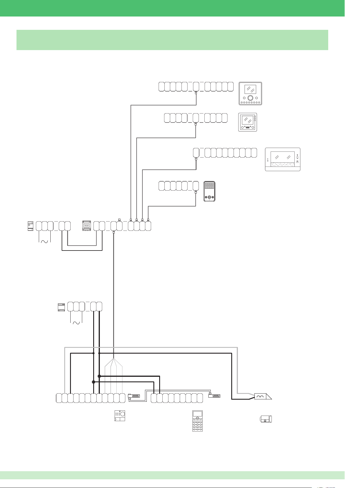
VIP/002
1441
6202W+
P
C
C
6501
Connecting Powercom series digital call module Art. 3370
0
V
OUT
G
AL
N
D P
S
0
A
F
V
N
P
IN
S
1
1
+
C
F
-
N
+
1
C
0
N
V
1
C
N
3
C
SS
N
+
1
OP+OP-0
C
F
AL
P
OP+OP
-
OUT
AL
V 1
P
0
A
V
N
C
P
S
F
A
+
P
N
6203W
OUT
0
AL
6231
6304
0
1V
V
1
2
1440
+
L
-
N
V V
IN
+
IN
-
21
OUT
OUT43OUTOUT
21
1395
C
N
O
C
M
2
3
0 0
0
R
D
N
O
T
-
O
E
1
2
TX
~
~
+
-
J2
-
+
~~
J1
RX
RXTX
4662C
T
P
-
R
D
-
-
XRX
3370
J1
D
J2
71
Page 72
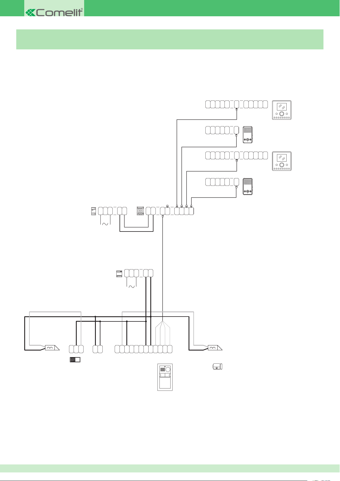
VIP/003
6202W+
6202W+
Connecting backlit module with actuator relay Art. 3327
P
C
0
A
F
V
N
P
C
S
0
N
V
+
1
OP+OP-0
V 1
OUT
AL
6231
1441
S S
-
0
V
-
C
N
+
1
C
S
N
+
1
C
SS
N
+
1
OP+OP
-
6203W
OUT
0
AL
1V
6203W
6231
G
AL
N
P
0
A
V
N
G
AL
N
D P
C
F
PD
C
F
P
C
F
1440
+
L
-
N
V V
IN
+
-
OUT
OUT43OUTOUT
21IN21
1395
2
1
3
0
0
2
0
72
N
C
SW1
C
N
O
M
12 12
O
~
~
C
O
CNONO
M
R
D
-
TX
TX RX
T
~
E
RX
~
-
+
+
-
4662C+3327
Page 73
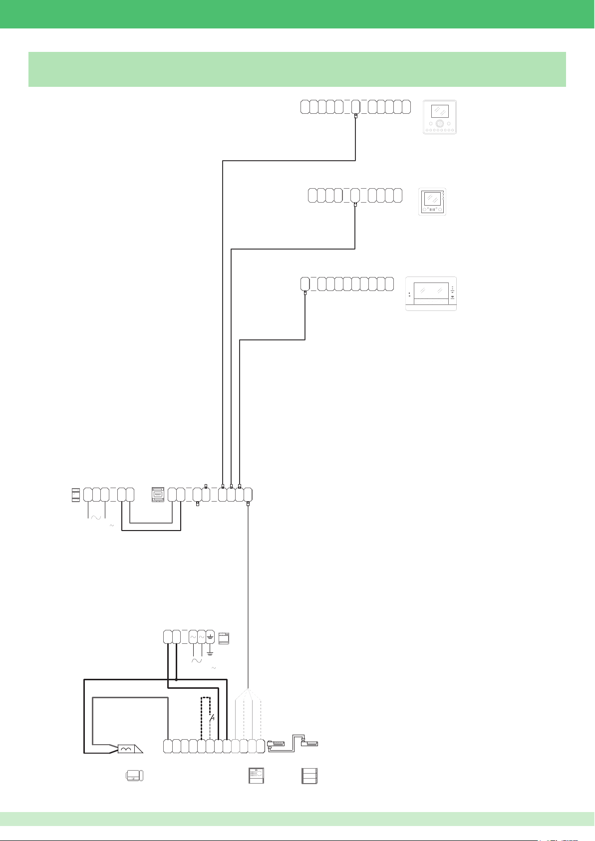
VIP/001I7
1441
6202W+
P
C
C
Connecting IKall call button module Art. 3343/3-4-6
OP+OP-0
C
F
AL
P
OUT
AL
1V
OUT
AL
V 1
P
0
A
V
N
0
V
6231
6304
1
2
6501
OUT
S
0
A
F
N
P
IN
1
1
N
V
+
1
C
S
0
N
V
+
1
C
P
S
OP+OP
-
0
F
A
+
P
N
0
V
C
N
3
L
100-240 V
1440
+
-
N
V V
IN
+
IN
-
21
OUT
OUT43OUTOUT
21
1595
+
-
120-230 V
G
C
S
O
E
M
NC NO
R
V V
N
T
-
D
E
RX
RXTX
TX
+
+
-
J2
-
+
4682C
J1J1
33436
73
Page 74
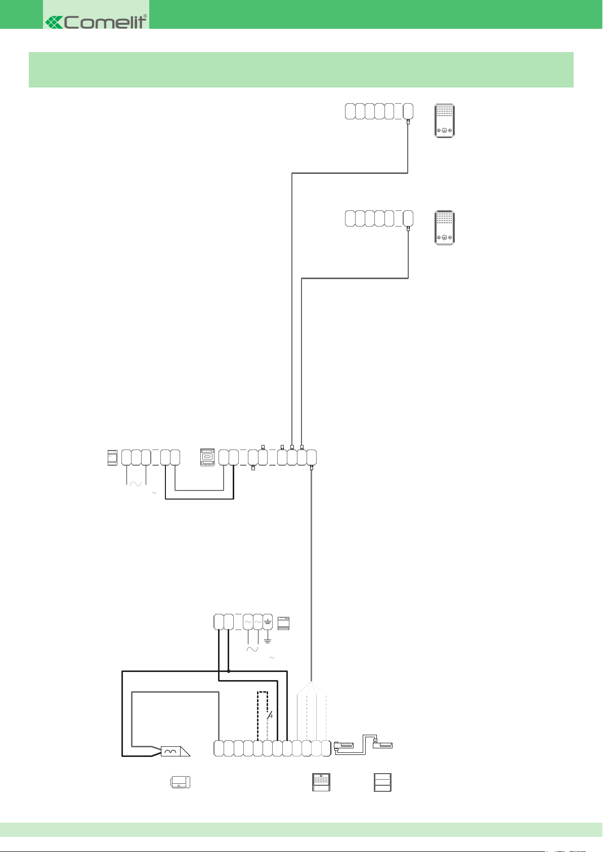
VIP/001IE
1441
C
6203W/
G
C
6203W/
Connecting IKall series audio unit for VIP system Art. 1682
SS
AL
N
D P
F
-
N
+
1
6203B
G
AL
N
D P
C
F
-
C
SS
N
+
1
6203B
1440
+
L
-
N
V V
IN
+
IN
-
21
OUT
OUT43OUTOUT
21
100-240 V
-
S
E
+
120-230 V
C
O
NC NO
M
G
N
D
1595
R
V V
T
-
E
RX
RXTX
TX
+
+
-
J2
-
+
1682
J1J1
33436
74
Page 75
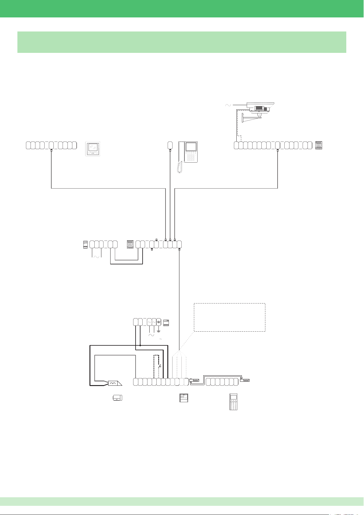
VIP/004I
1445
Connecting IKall series digital call module Art. 3360A
C
C
OUT
IN
S
0
1
1
N
V
+
1
P
0
F
A
AL
V
P
N
1441
6304
1440
+
-
L
N
V V
IN
+
-
C
N
1
OUT43OUTOUT
OUT
21IN21
1952
SV
1SV2
H H
SV
SV
3
4
H
H
G
CN
N
1
D
D D
+
A
G
U
N
-
X
D
TX -ORANGE WIRE
1595
+
-
WHITE/ORANGE WIRE
GREEN WIRE
WHITE/GREEN WIRE
TX +
RX -
RX +
S
E
120-230 V
C
O
NC NO
M
R
G
V V
TX
T
N
+
-
-
E
D
RX
-
+
4682C
J1
P
G
RXTX
J2
+
R
G D
485
N
+
D
D
-
3360A
J1
24485
S
J2
Vac24Vac
75
Page 76
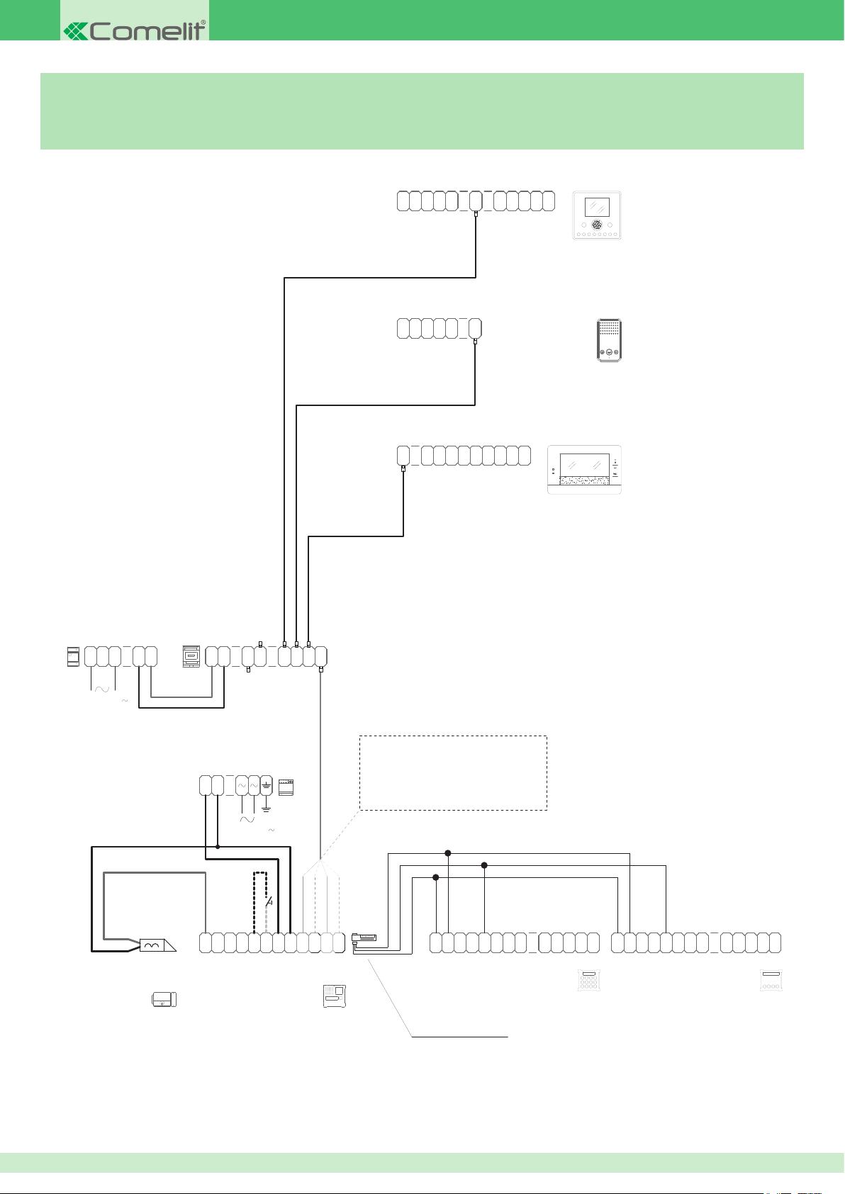
1441
6202W+
3072B
2E7T000696
VIP/002DVI
Connecting Vandalcom series digital call modules Art. 3070B and Art. 3072B
with IKall series external units Art. 4682C or 1682
P
C
0
A
F
V
N
P
C
S
0
N
V
+
1
OP+OP-0
V 1
OUT
AL
6231
L
100-240 V
G
AL
N
D P
C
N
3
C
F
C
SS
N
+
-
1
C
P
S
OP+OP
F
+
-
P
OUT
0
A
N
0
AL
1V
V
1
2
6203W
6501
1440
+
-
N
V V
IN
+
-
OUT
OUT43OUTOUT
21IN21
-
S
E
+
120-230 V
G
C
N
O
NC NO
D
M
4682C+3268I/1
1595
R
V V
T
-
E
RX
TX
+
-
+
-
1682+3268I/1
WHITE/ORANGE WIRE
GREEN WIRE
WHITE/GREEN WIRE
J1
RXTX
J2
+
12~12
VV
+
"V " BLUE
-
S
-
~
"S" YELLOW
"V+" BROWN
TX -ORANGE WIRE
TX +
RX -
RX +
T
P
-
-
R
D
-
X
XR
+ +
-
12~12
VV
+
-
S
-
~
P
-
R X
R-T
D
DD
X
-
3070B
76
Page 77
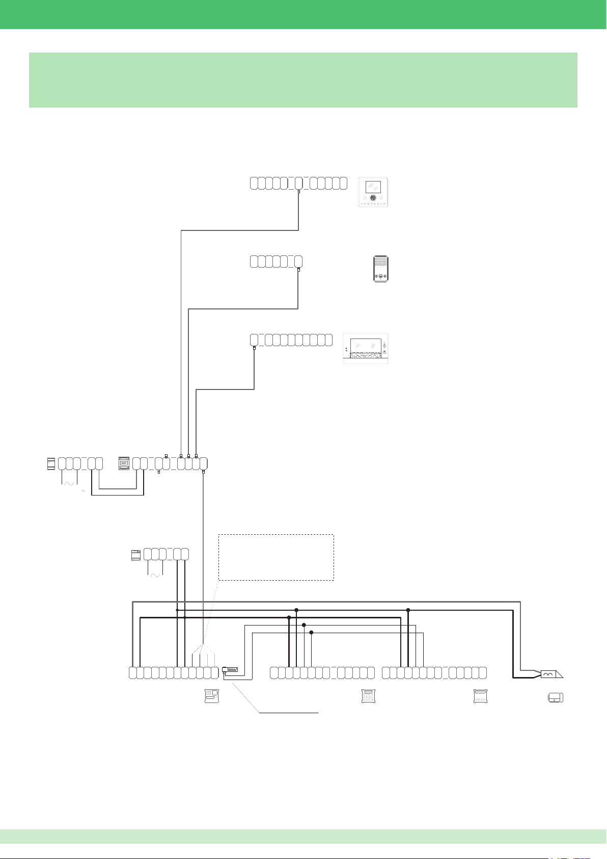
1441
6202W+
P
C
C
2M1500299
VIP/001IE
Connecting Vandalcom series digital call modules Art. 3270 and Art. 3272
with Powercom series external unit Art. 4662C
OP+OP-0
0
AL
OUT
AL
V 1
6231
6203W
OUT
0
1V
V
6501
1
2
S
0
0
A
V
N
G
AL
N
D P
C
N
3
N
F
V
+
1
P
C
C
SS
N
F
+
-
1
C
P
S
OP+OP
F
A
+
-
P
N
1440
+
-
L
N
V V
IN
+
-
OUT43OUTOUT
OUT
21IN21
100-240 V
1395
0
C
O
-
CNONO
M
1
1
2
0
2
0
R
D
TX
TX RX
T
~
~
-
+
E
4662C+3269/1
WHITE/ORANGE WIRE
GREEN WIRE
WHITE/GREEN WIRE
J1
RX
J2
+
-
12
~
S
~
~12~
*
" " ORANGE
-
"S" YELLOW
TX -ORANGE WIRE
TX +
RX -
RX +
-
T
P
-
R
D
D
-
XR
3270
12~12
~
~
X
*
S
-
~
P
D
D
-
R X
-
R-T
3272
X
77
Page 78
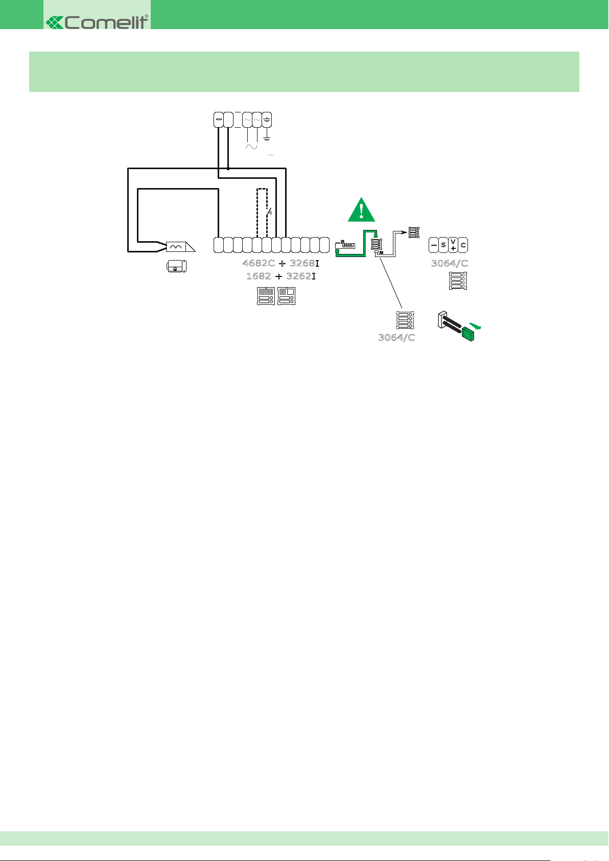
3064/C
1595
Connecting Art. 3064/C with audio-video unit 4682C or audio unit
Art. 1682
+
-
120-230 V
Use the cable included in Art. 3262I, Art. 3268I
R
G
C
S
O
NC NO
E
M
4682C + 3268I
1682 + 3262I
V V
TX
T
N
+
+
-
-
E
D
J1
RX
RXTX
-
+
J2
V
S
-
C
+
3064/C
CV3
Remove jumper
78
Page 79
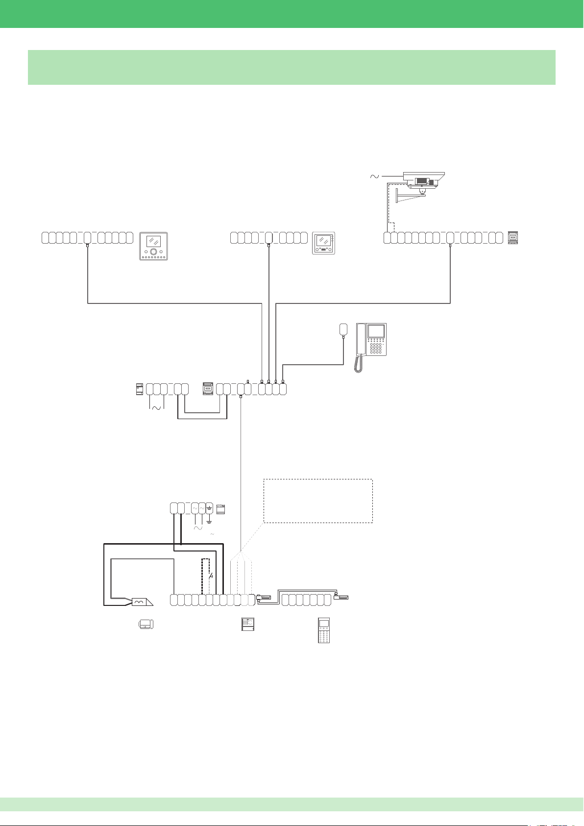
VIP/004
1445
Connecting remote camera module Art. 1445
P
C
C
S
0
0
A
F
V
N
N
V
+
P
1
OP+OP-0
V 1
OUT
AL
6202W+
6231
OUT
1
C
C
IN
S
0
1
V
+
P
N
1
0
F
A
AL
V
P
N
6304
SV
1SV2
H H
G
A
D D
+
G
U
N
-
X
D
CN
SV
SV
N
3
1
4
H
H
D
1441
C
N
1
1440
+
-
L
N
V V
IN
+
-
OUT43OUTOUT
OUT
21IN21
1952
TX -ORANGE WIRE
1595
+
-
WHITE/ORANGE WIRE
GREEN WIRE
WHITE/GREEN WIRE
120-230 V
G
C
R
NC NO
V V
TX
N
T
+
-
-
D
E
S
O
E
M
RX
-
+
4682C
J1
P
G
485
RXTX
+
R
J2
G D
24485
N
S
+
D
D
-
3360A
TX +
RX -
RX +
J1
J2
Vac24Vac
79
Page 80
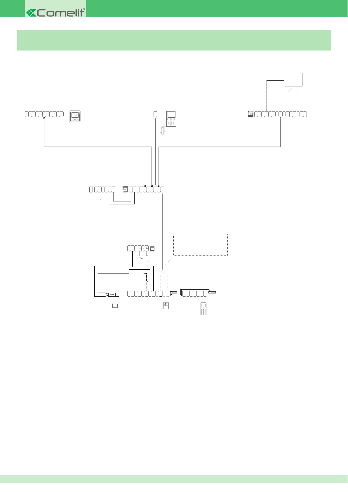
MONITOR
OUT
VIP/007I
Connecting PAL / NTSC module Art. 1446
C
C
IN
S
0
1
1
V
+
P
0
N
F
A
AL
V
1
P
N
6304
1441
1440
+
-
L
N
V V
+
-
C
N
1
IN
OUT
21IN21
1952
OUT43OUTOUT
1446
S
C Y-V
GND
C
O
M
G
S
P
K
CN
1 12
IN
IN
OUT OUT
N
2
1
D
TX -ORANGE WIRE
1595
+
-
120-230 V
WHITE/ORANGE WIRE
GREEN WIRE
WHITE/GREEN WIRE
TX +
RX -
RX +
G
C
R
NC NO
V V
N
T
+
-
D
E
S
O
E
M
TX
-
RX
-
+
4682C
J1
P
G
RXTX
+
485
R
N
J2
D
-
G D
+
D
3360A
J1
24485
S
J2
Vac24Vac
80
Page 81
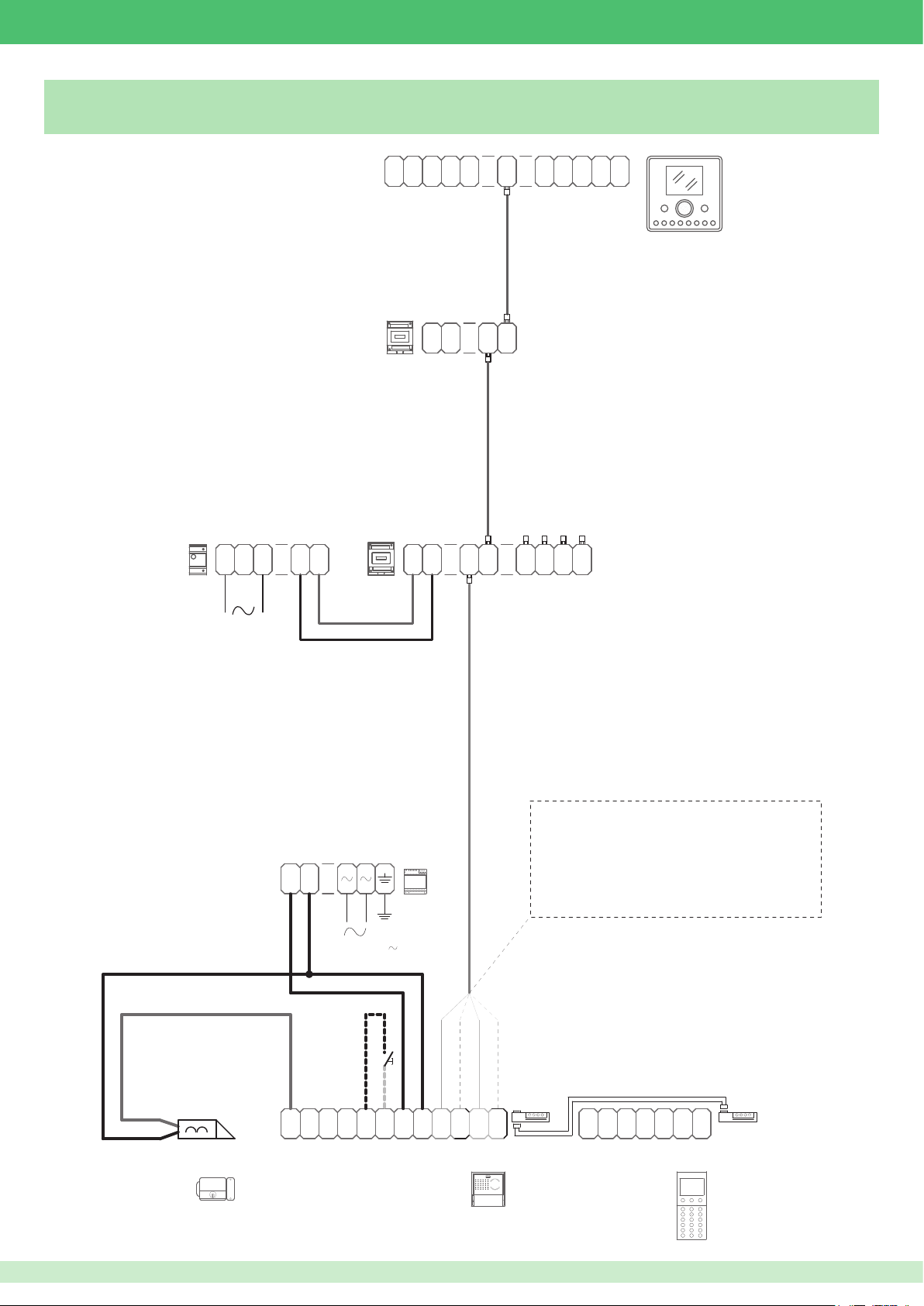
6202W+
VIP/005
Connecting repeater module Art. 1447
1441
C
P
0
V
0
F
A
V
P
N
C
S
+
OP
N
+
1
OP
-
OUT
0
AL
1V
6231
1447
+
-
IN
OUT
1440
+
L
-
N
V V
+
IN
IN
-
OUT
21
OUT
OUTOUT
43
21
-
S
E
+
120-230 V
C
O
NC NO
M
G
N
D
1595
R
V V
T
-
E
+
TX
+
4682C
RX
-
TX -ORANGE WIRE
WHITE/ORANGE WIRE
GREEN WIRE
WHITE/GREEN WIRE
J1
RXTX
J2
+
P
R
G D
G
485
N
+
D
D
-
24
24485
S
Vac
Vac
TX +
RX -
RX +
J1
J2
3360A
81
Page 82
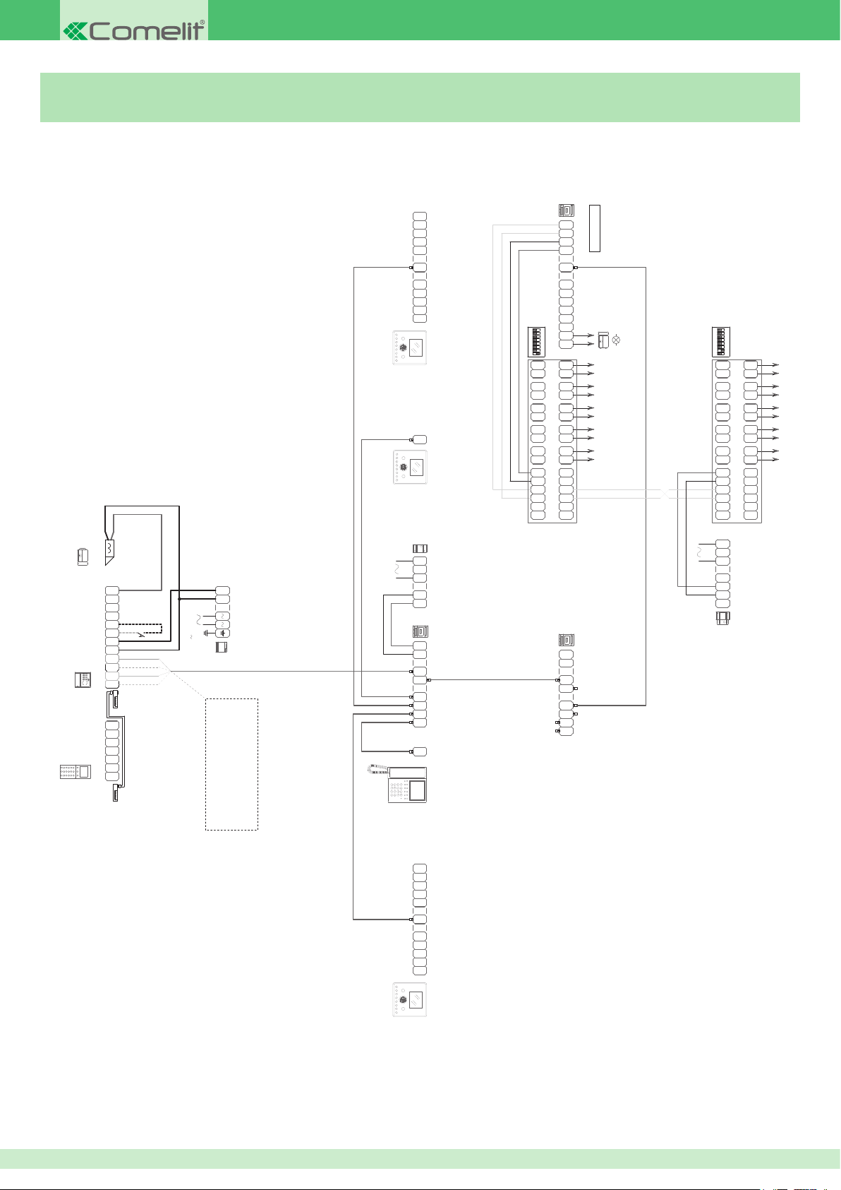
SW 4902
VIP/010
Connecting IO module Art. 1443 and expansion device Art. SK9071
RS 485
1443
V
N
A
P
F
V
+
N
1
+
-
1V
6231
N
1
6231
0
P
C
0
S
C
OP
OP
0
OUT
6202W
C
6202W
ON
1234 675 8
BABA BA BA BA
+
-
SK9071
D-D+
BA
VIP 201
+
D D
-
G
D
N
12
V
CN
G
D D
N
IN
IN
211
G C
N
OC
1
NC NO
M
O
B
AB A B A B A
B A
B A
D- D+
-
+
12V/24V
AC-DC
ON
1234 675 8
B AB A B A B A
BABA BA BA BA
B A
+
B A
-
D- D+
SK9071
D-D+
-
+
BA
E
M
D
E
-
+
-
4682C
+
-
+
J2
G D
D
-
D
+
3360A
Vac
Vac
J2
1441
0
S
O
C
NC NO
G
N
R
T
V V
TX
RX
RXTX
J1
R
P
G
N
485
S
24485
24
J1
-
+
120-230 V
1595
WHITE/ORANGE WIRE
WHITE/GREEN WIRE
GREEN WIRE
RX +
RX -
TX +
TX -ORANGE WIRE
0
5
+
-
1 2
1 2
3 4
N
1
V
N
A
P
F
V
+
N
1
+
-
V 1
ALAL
230
5
IN
IN
OUT
OUTOUT
OUT
C
1952
0
P
C
0
S
C
OP
OP
0
OUT
1440
1440
+
-
IN
1 2
IN
OUT
1 2
OUTOUT
3 4
OUT
~ ~
+
+
-12Vcc
82
6231
6202W
Page 83
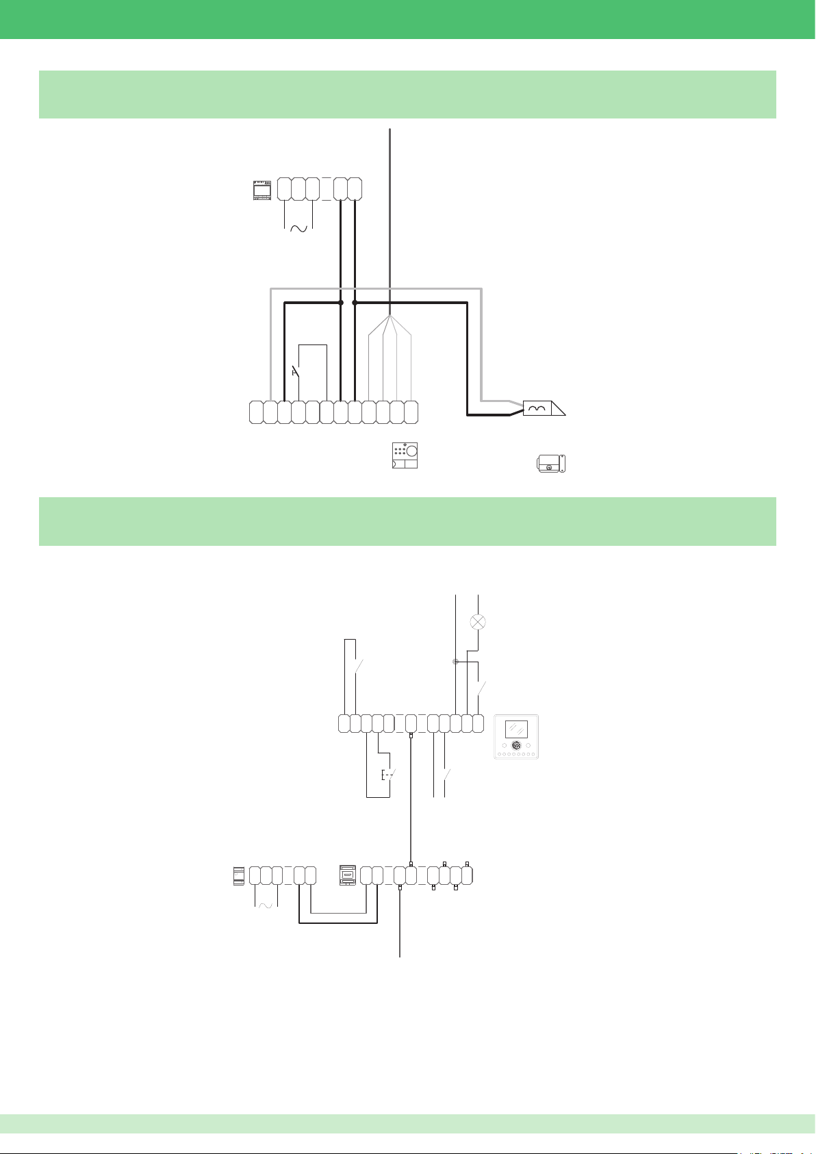
100mA MAX
6202W
1441
VIP/RTE
Request to exit (RTE) button input variant
1395
C
N
O
C
M
2
3
0 0
0
D
N
-
O
O
1
2
R
TX
T
~
~
+
-
E
4662C
VIP/FMP
Planux VIP output and input variant
RX
-
RXTX
+
FIRE ALARM
-
N
L
+
VV
0
V
CFP
1440
12 Vdc
+
-
LED FUNCTION
ALARM
C
P
F
A
P
N
C
S
0
N
V
+
1
OUT
OP+OP
0
AL
1V
-
-
+
6231
12 Vdc
IN
OUT
OUTOUT
+
-
1 2IN1 2
3 4
OUT
83
Page 84
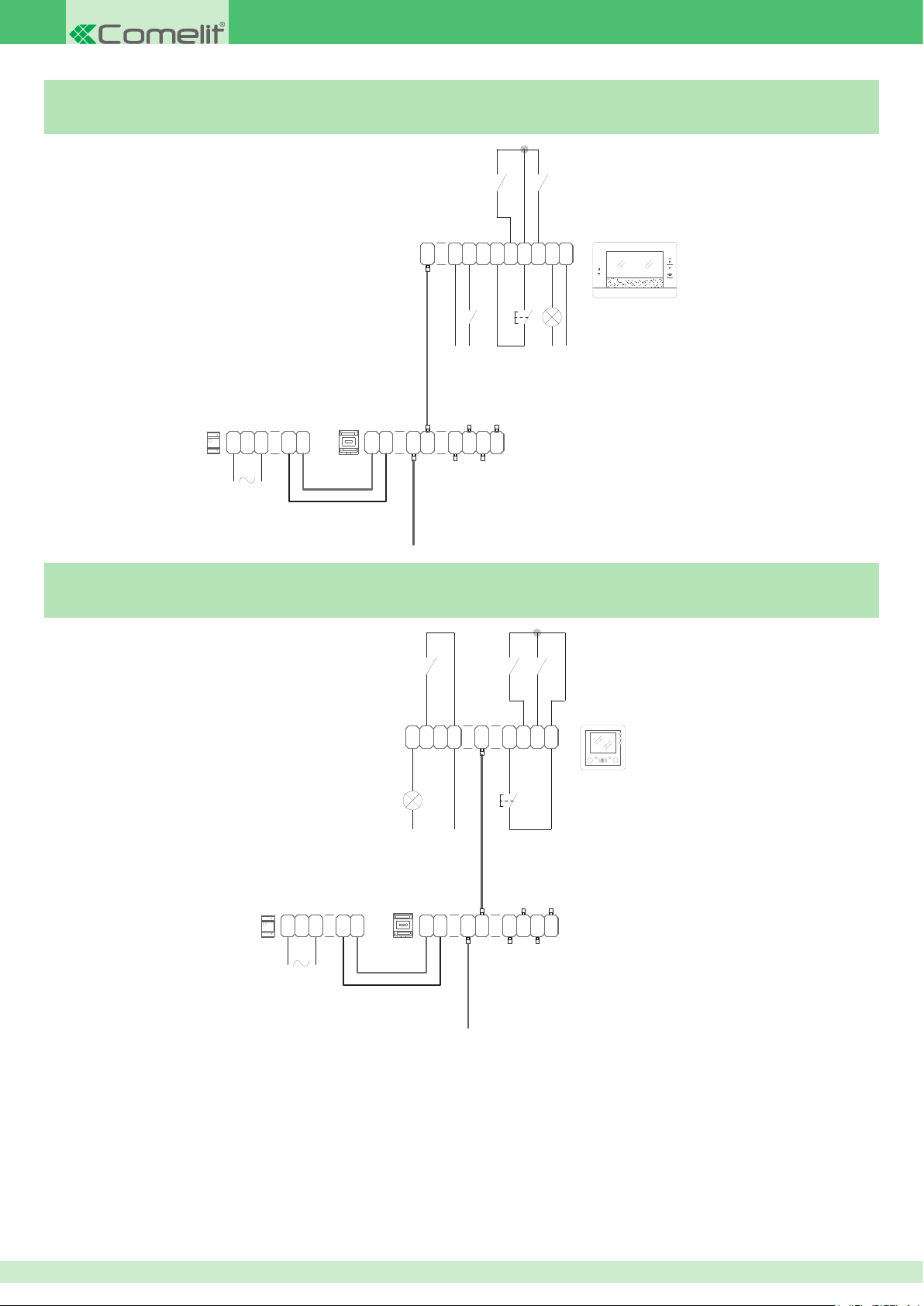
6501
1441
1441
6304
7Stelle output and input variant
VIP/FM7
ALARMFIRE ALARM
1440
+
L
VV
-
N
+
-
Smart output and input variant
C
N
3
+
12 Vdc
IN
OUT
1 2IN1 2
VIP/FMS
C
P
S
OP+OP
F
+
-
P
OUT
0
A
N
0
AL
1V
V
LED FUNCTION
-
CFP
-
+
12 Vdc
100mA MAX
OUTOUT
OUT
3 4
ALARM PANIC
1
2
LED FUNCTION
N
L
C
C
OUT
IN
S
0
1
1
N
V
+
1
P
0
F
A
AL
V
P
N
CFP
-
+
12 Vdc
100mA MAX
1440
+
-
VV
+
-
IN
OUT
1 2IN1 2
OUTOUT
3 4
OUT
84
Page 85

1441
6203W/
Easycom output and input variant
2G60000653
1595
MAX N° 4
VIP/FME
ALARM
-
CFP
C
SS
N
+
1
6203B
G
AL
N
D P
C
F
1440
L
VV
+
-
N
+
-
IN
OUT
1 2IN1 2
OUTOUT
3 4
OUT
Connection of Vandalcom nameplate lighting lamp with audio unit
Art. 1682 or audio-video unit Art. 4682C (Ikall)
+
-
CV1
120-230 V
R
G
C
S
O
NC NO
E
M
V V
T
N
-
E
D
RX
RXTX
TX
+
-
+
+
-
2G60001021
+
-
VinVout
12Vdc16Vdc
+
-
1682+3262I
4682C+3268I
85
Page 86
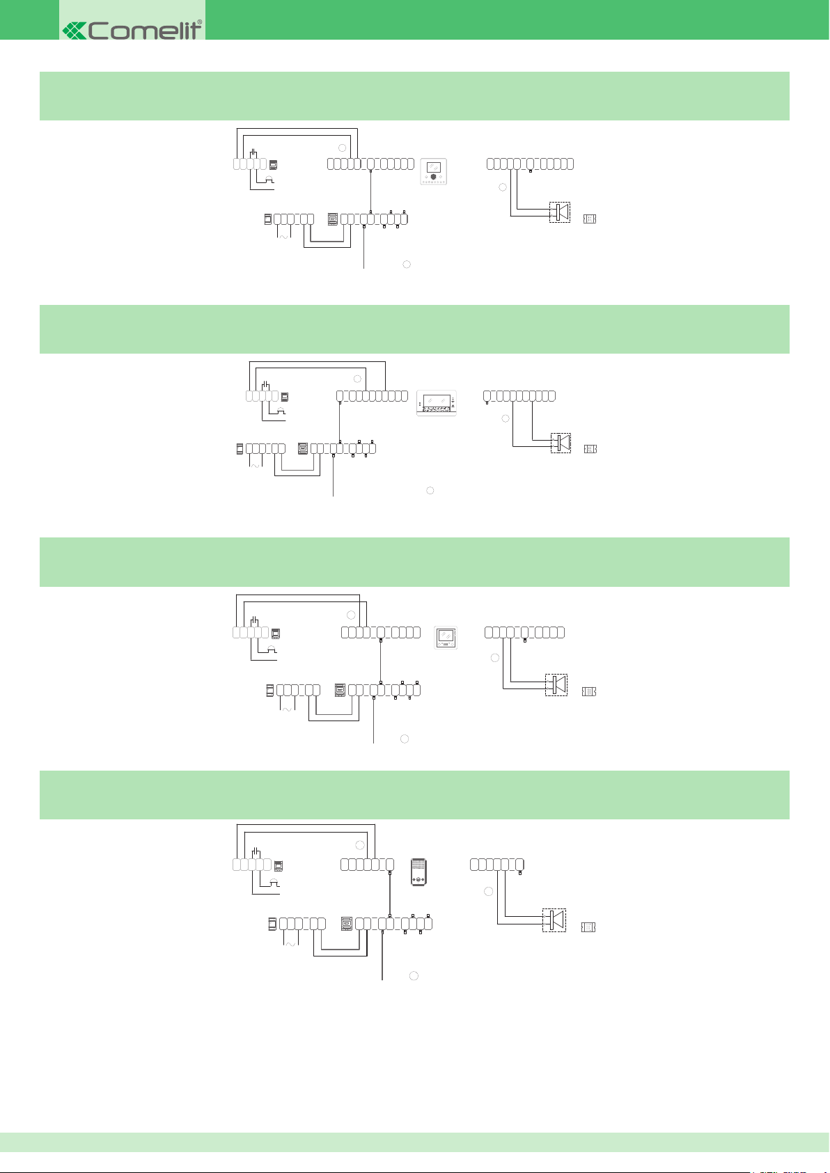
1229
*
1441
1229
20 m MAX
1229
*
1229
*
20 m MAX
VIP/FMPS
Connecting Planux VIP additional ringtone variant
470nF
N
1122/A
C
+
-
ONC
(12V)
12/24V
AC/DC
1441
N
L
*
C
C
P
S
0
0
F
A
V
V
+
P
N
1440
+
-
+
-
VV
N
1
IN
1 2IN1 2
OUT
OP+OP
0
AL
1V
-
OUT
OUTOUT
OUT
3 4
6202W
6231
P
0
A
V
N
20 m MAX
VIP/FM7S
Connecting 7Stelle additional ringtone variant
-
C
N
3
IN
1 2IN1 2
OUT
*
OP+OP
-
OUTOUT
C
P
S
F
A
+
P
N
OUT
3 4
OUT
0
0
AL
1V
V
VIP/FMSS
C
6501
1
N
2
3
*
470nF
N
1122/A
C
+
-
ONC
(12V)
12/24V
AC/DC
1440
+
-
N
L
+
VV
C
C
S
0
F
V
+
P
OUT
OP+OP
0
N
AL
1V
-
1
*
C
P
OUT
S
OP+OP
0
0
F
A
AL
1V
V
+
-
P
N
*
Connecting Smart additional ringtone variant
470nF
N
1122/A
C
+
-
ONC
(12V)
12/24V
AC/DC
1441
-
N
L
*
C
C
OUT
IN
S
0
1
1
V
+
P
0
N
F
A
AL
V
1
P
N
6304
C
OUT
IN
S
0
N
1
1
V
+
1
*
1440
+
VV
IN
OUT
OUTOUT
1 2IN1 2
OUT
3 4
+
-
20 m MAX
VIP/FMES
Connecting Easycom additional ringtone variant
470nF
N
1122/A
C
+
-
ONC
(12V)
12/24V
AC/DC
1441
-
N
L
*
G
AL
N
D P
C
C
SS
N
F
+
-
6203W/
1
6203B
G
N
D P
C
C
SS
N
AL
F
+
-
1
*
1440
+
VV
IN
OUT
OUTOUT
+
-
1 2IN1 2
OUT
3 4
C
P
0
F
A
AL
V
P
N
86
Page 87

87
Page 88

2nd edition Rev.3 03/2016 code 2G40001073
www.comelitgroup.com
Via Don Arrigoni, 5 - 24020 Rovetta (BG) - Italy
 Loading...