

Page 1
EN
TECHNICAL
MANUAL
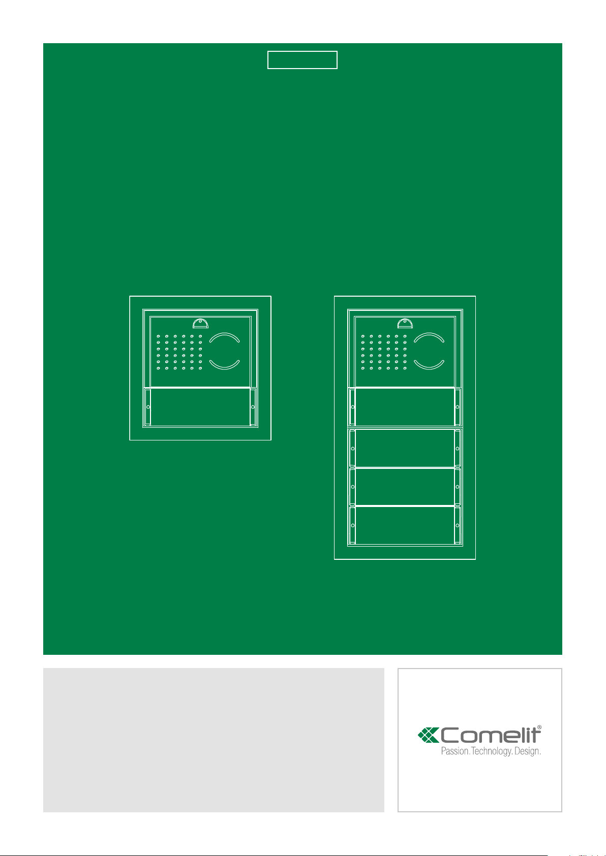
Technical manual for Ikall external unit Art. 4681
and power supply unit Art. 1210
Page 2

Warning
• Install the equipment by carefully following the instructions given by the manufacturer and in compliance with the
standards in force.
• All the equipment must only be used for the purpose it was designed for. Comelit Group S.p.A. does not assume
responsibility for improper use of the apparatus, for modifications made by third parties for any reason or purpose,
or for the use of non-original accessories and materials.
• All the products comply with the requirements of the 2014/30/EU and 2014/35/EU directives. This is proved by the
CE mark on the products themselves.
• Do not route the riser wires in proximity to power supply cables (230/400V).
• Installation, mounting and assistance procedures for electrical devices must only be performed by specialised
electricians.
• Disconnect the power supply before carrying out any maintenance operations.
• The camera must not be installed opposite bright light sources, or in places where the filmed subject is against the
light.
• In poor light conditions, cameras with colour sensors are less sensitive than black and white cameras. We therefore
recommend, in dimly lit environments, to install an additional light source.
• Connect the module support frame to earth (see Fig.)
Table of contents
Warning......................................................................................................... 2
Table of contents......................................................................................... 2
Description ................................................................................................... 3
External unit installation ............................................................................ 4
Installation information ........................................................................................5
Button programming .................................................................................. 6
Dip switch programming table ................................................................. 7
EXAMPLE: dip switch setting for code 200......................................................8
Special programmes .................................................................................. 9
Power supply unit Art. 1210 ....................................................................12
Consumption management .................................................................... 13
External unit module consumption table .......................................................13
Operating distances with Art. 1210 ........................................................14
Distances valid for articles: 6700W, 6701W, 6701B, 6721W, 6801W ...........14
Distances valid for Art. 6601W .........................................................................15
Maximum system expansion ............................................................................15
Wiring diagrams ........................................................................................ 16
Video entry phone system with 1 external unit Art. 4681: system
commissioning/voltage test with system at rest. .........................................16
Wiring diagram for system with external unit 4681
and supplementary power supply unit Art. 1595
(for maximum number of expansion modules). ............................................17
Wiring diagram for system with digital call module Art. 3360B ..................18
Wiring diagram for system with external unit Art. 300(1-12)XVB ...............18
Wiring diagram for system with electronic digital key module Art. 3348B 19
Wiring diagram for system with electronic digital key module Art. 3348B
and supplementary power supply unit Art. 1595 (for maximum number of
expansion modules). ..........................................................................................20
Wiring diagram for system with single-plate entrance panel Art. 3063D .21
Wiring diagram for system with single-plate entrance panel Art. 3063D
with supplementary power supply unit Art. 1595 (for maximum number of
expansion modules). ..........................................................................................22
Wiring diagram for system with Vandalcom entrance panel and
conventional button modules Art. 3064S .......................................................23
Wiring diagram for systems with Vandalcom entrance panel and
conventional button modules Art. 3064S and supplementary power supply
unit Art. 1595 (for maximum number of expansion modules). ....................24
Wiring diagram for systems with digital call modules Art. 3070S and
Art.3072S ..............................................................................................................25
Wiring diagram for systems with Vandalcom electronic key module Art.
3188S ....................................................................................................................26
Wiring diagram for systems with Art. SK9015 for connection of readers Art.
SK9000I and Art. SK9001I..................................................................................27
Use of external unit relay on lock release or actuator command ..............28
Use of RC network for lock filter on relay contacts .....................................28
Wiring diagram with safety lock .......................................................................28
Wiring diagrams for system with switching device Art. 1404 ........... 29
System with Art. 1210: switching device in STANDARD
mode and 2 inputs ..............................................................................................29
System with Art. 1210: switching device in STANDARD
mode, 1 main input and 2 secondary inputs ..................................................30
System with Art. 1210: switching devices in STANDARD
mode and 8461 KIT in cascade ........................................................................32
System with Art. 1210: switching devices in STANDARD
mode, branched 8461 KIT .................................................................................34
Wiring digram for systems with camera module Art. 1409 ............... 35
System Art. 1210: remote camera module Art. 1409 in generic
actuator mode .....................................................................................................35
2
Page 3
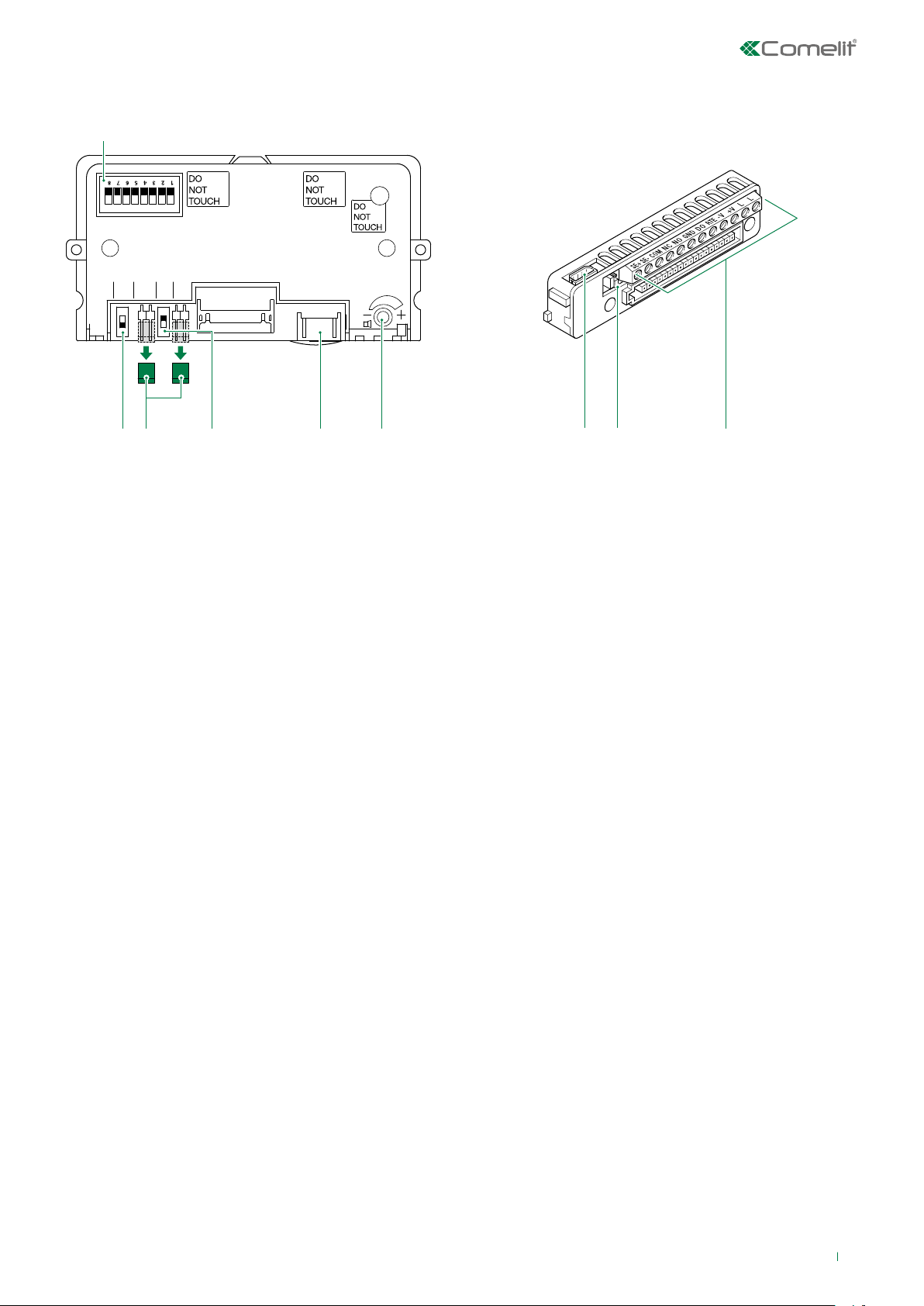
1.
2. 3. 5. 6.4.
7. 8.
9.
Description
ON DIP
PR
J11 CNF J9
ON
OFF
1. S1 DIP switches for function programming and setting the user code.
2. PR switch for input/output programming.
3. J11 jumper for power supply management. Remove in case of power on V+ and V-.
J9 jumper for power supply management. Remove in case of power on V+ and V-.
4. CNF switch for confirming special programmes.
5. CAUTION: connector reserved for the module 1621VC.
6. Loudspeaker volume control.
7. 8-pole cable connector.
8. JP1 RC network management for door lock filter on relay contacts (see page 28).
9. Terminal block for connection:
SE+ SE- electric lock connection
COM common relay contact
NC normally closed relay contact
NO normally open relay contact
GND input reference negative for DO-RTE
DO door opened signal input
RTE local lock release input
V- power supply negative
V+ power supply positive
LL bus line connection
3
Page 4
-L
+L
PR CNF
1. 4.
3.2.
42,5 cm
7.
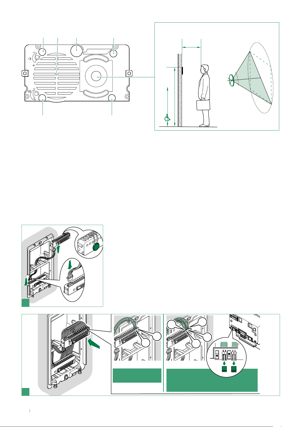
1. Signalling LED: call sent.
2. Speaker.
3. Microphone.
4. Signalling LED: system busy.
5. Colour camera.
6. Signalling LED: sound activated.
7. Signalling LED: lock release activated.
6.
External unit installation
5.
100°
163 cm
130 cm
1
+V
+L
-L
J11 J9
A powered by
Art. 1210
-V
B powered by
power supply unit
Art. 1595
2
4
Page 5
LED
O
F
F
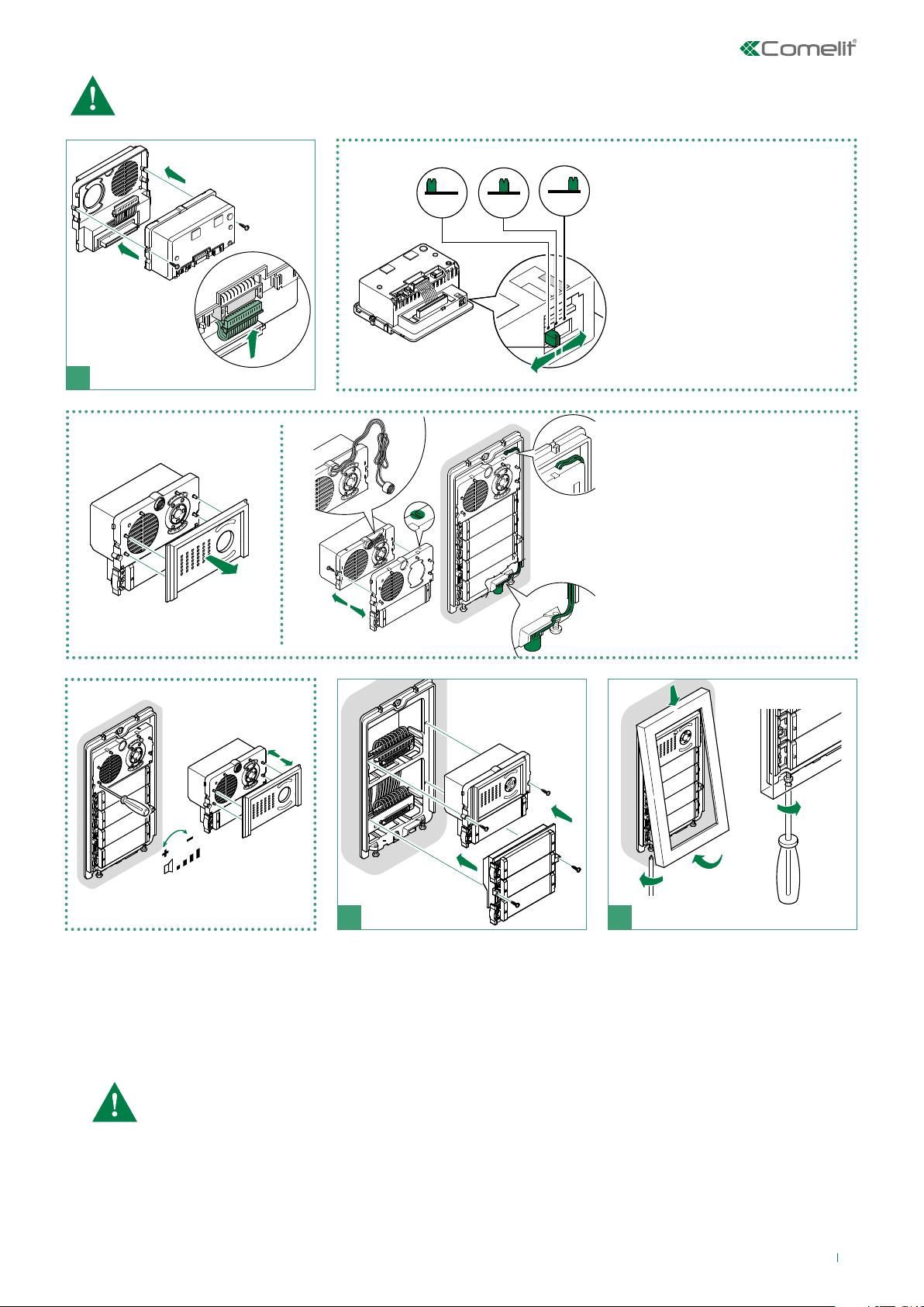
COMPLETE MT ONLY
3
2
1
5
4
If the total power consumption of the modules exceeds 100mA then it will be necessary to use the power
supply unit Art. 1595.
To calculate the power consumption values see “Consumption management” on page 13.
1
WHITE OFF
BLUE
1
LED
O
F
F
Nameplate LED lighting
2
selection.
3
3
2
1
4
5
Alternative microphone position
(excluding 4 module entrance panel)
1
360°
open
2
Speaker adjustment
54
3
close
Installation information
• The module Art. 4681 operates by default as a main external unit (timed busy signal). To set it as a secondary external unit
(busy signal active for the whole time the riser is in use), set all the selector DIP switches to ON.
• When a call is transmitted from the external unit, if a busy tone is heard instead of the ringtone, this means communication
with another external unit is in progress.
Art. 4681 must only be used while powered by Art. 1210.
5
Page 6
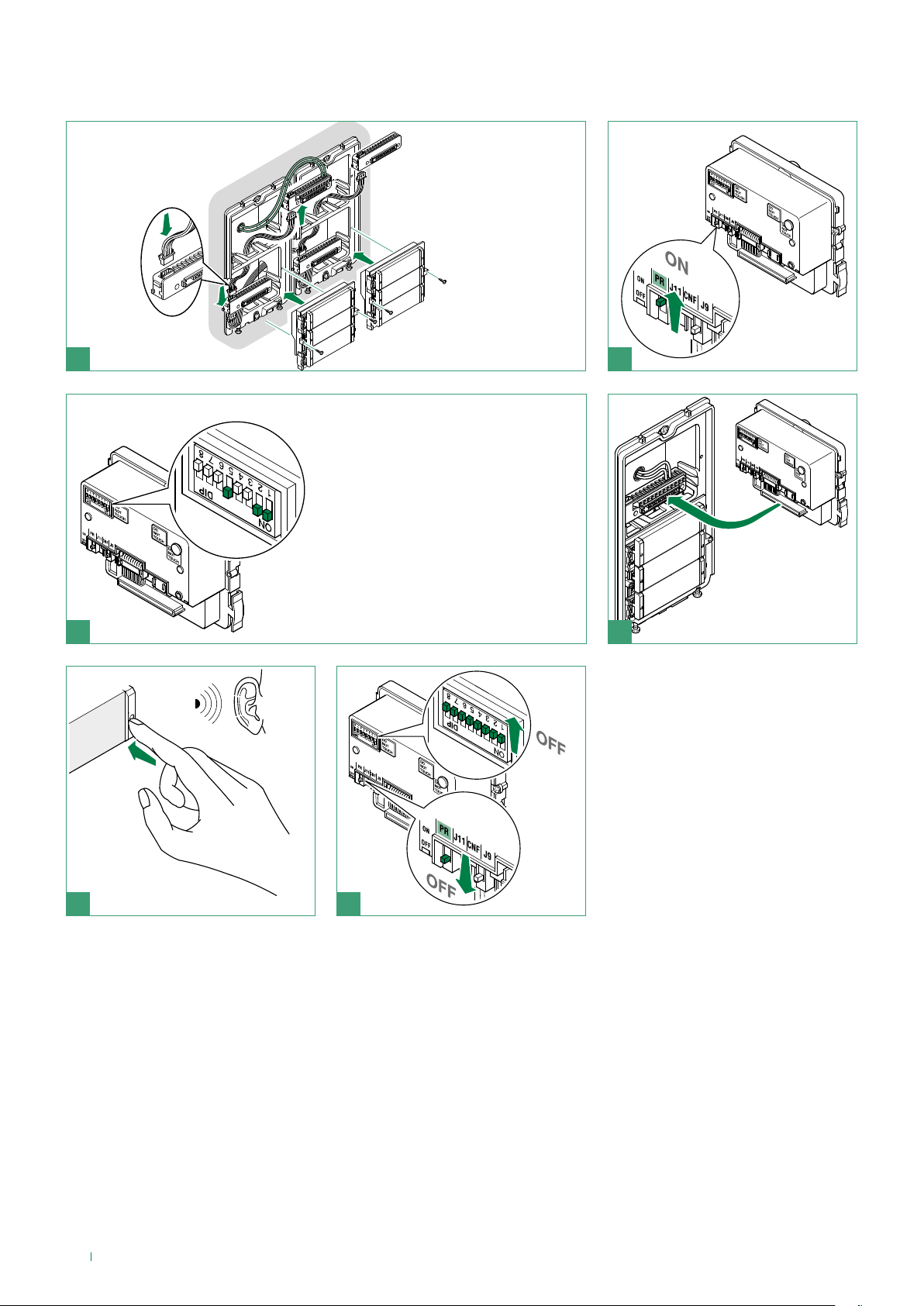
Button programming
1
33433
33434
33436
Set the user code using the dip
switches; see the table on page 7.
2
3
1
2
4
65
6
Page 7
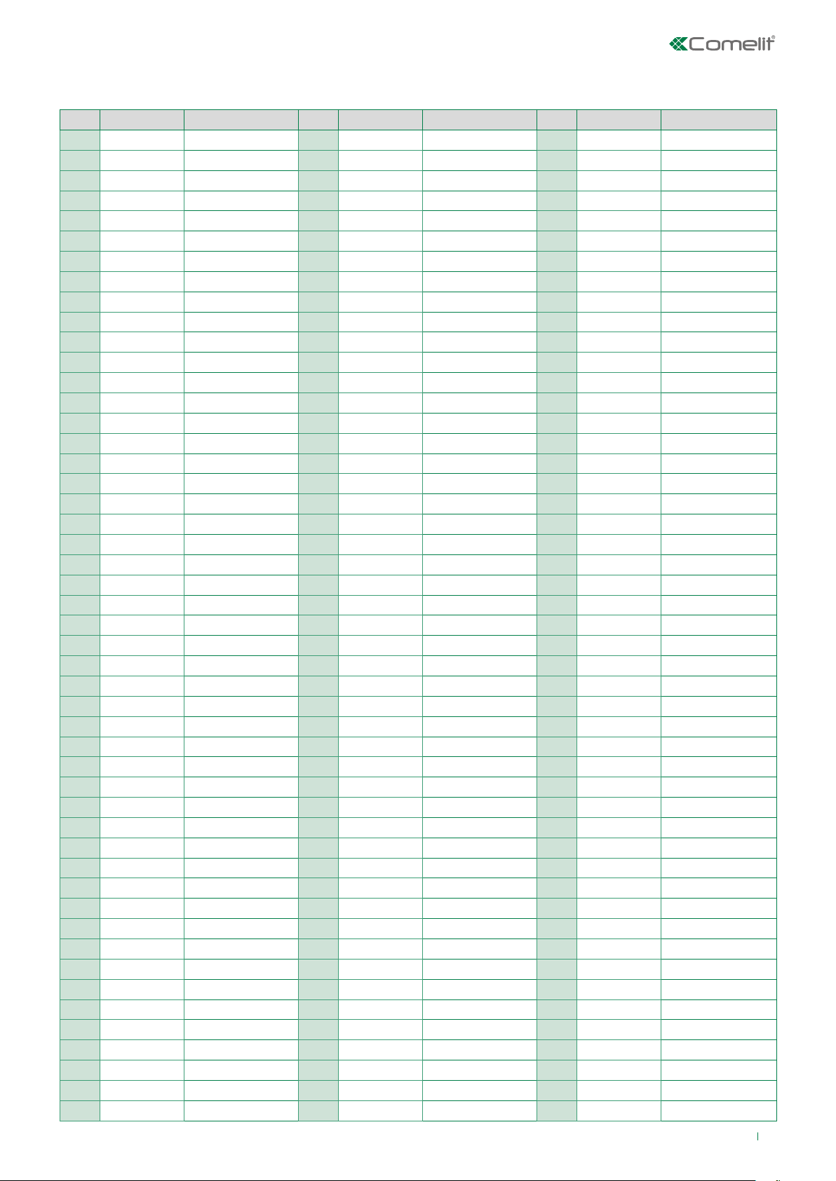
Dip switch programming table
Code Dip switch ON Name
1 1
2 2
3 1.2
4 3
5 1.3
6 2.3
7 1,2,3
8 4
9 1.4
10 2.4
11 1,2,4
12 3.4
13 1,3,4
14 2,3,4
15 1,2,3,4
16 5
17 1.5
18 2.5
19 1,2,5
20 3.5
21 1,3,5
22 2,3,5
23 1,2,3,5
24 4.5
25 1,4,5
26 2,4,5
27 1,2,4,5
28 3,4,5
29 1,3,4,5
30 2,3,4,5
31 1,2,3,4,5
32 6
33 1.6
34 2.6
35 1,2,6
36 3.6
37 1,3,6
38 2,3,6
39 1,2,3,6
40 4.6
41 1,4,6
42 2,4,6
43 1,2,4,6
44 3,4,6
45 1,3,4,6
46 2,3,4,6
47 1,2,3,4,6
48 5.6
49 1,5,6
Code Dip switch ON Name
50 2,5,6
51 1,2,5,6
52 3,5,6
53 1,3,5,6
54 2,3,5,6
55 1,2,3,5,6
56 4,5,6
57 1,4,5,6
58 2,4,5,6
59 1,2,4,5,6
60 3,4,5,6
61 1,3,4,5,6
62 2,3,4,5,6
63 1,2,3,4,5.6
64 7
65 1.7
66 2.7
67 1,2,7
68 3.7
69 1,3,7
70 2,3,7
71 1,2,3,7
72 4.7
73 1,4,7
74 2,4,7
75 1,2,4,7
76 3,4,7
77 1,3,4,7
78 2,3,4,7
79 1,2,3,4,7
80 5.7
81 1,5,7
82 2,5,7
83 1,2,5,7
84 3,5,7
85 1,3,5,7
86 2,3,5,7
87 1,2,3,5,7
88 4,5,7
89 1,4,5,7
90 2,4,5,7
91 1,2,4,5,7
92 3,4,5,7
93 1,3,4,5,7
94 2,3,4,5,7
95 1,2,3,4,5.7
96 6.7
97 1,6,7
98 2,6,7
Code Dip switch ON Name
99 1,2,6,7
100 3,6,7
101 1,3,6,7
102 2,3,6,7
103 1,2,3,6,7
104 4,6,7
105 1,4,6,7
106 2,4,6,7
107 1,2,4,6,7
108 3,4,6,7
109 1,3,4,6,7
110 2,3,4,6,7
111 1,2,3,4,6.7
112 5.67
113 1,5,6,7
114 2,5,6,7
115 1,2,5,6,7
116 3,5,6,7
117 1,3,5,6,7
118 2,3,5,6,7
119 1,2,3,5,6.7
120 4,5,6,7
121 1,4,5,6,7
122 2,4,5,6,7
123 1,2,4,5,6.7
124 3,4,5,6,7
125 1,3,4,5,6.7
126 2,3,4,5,6.7
127 1,2,3,4,5,6,7
128 8
129 1.8
130 2.8
131 1,2,8
132 3.8
133 1,3,8
134 2,3,8
135 1,2,3,8
136 4.8
137 1,4,8
138 2,4,8
139 1,2,4,8
140 3,4,8
141 1,3,4,8
142 2,3,4,8
143 1,2,3,4,8
144 5.8
145 1,5,8
146 2,5,8
147 1,2,5,8
7
Page 8
Code Dip switch ON Name
148 3,5,8
149 1,3,5,8
150 2,3,5,8
151 1,2,3,5,8
152 4,5,8
153 1,4,5,8
154 2,4,5,8
155 1,2,4,5,8
156 3,4,5,8
157 1,3,4,5,8
158 2,3,4,5,8
159 1,2,3,4,5.8
160 6.8
161 1,6,8
162 2,6,8
163 1,2,6,8
164 3,6,8
165 1,3,6,8
166 2,3,6,8
167 1,2,3,6,8
168 4,6,8
169 1,4,6,8
170 2,4,6,8
171 1,2,4,6,8
172 3,4,6,8
173 1,3,4,6,8
174 2,3,4,6,8
175 1,2,3,4,6.8
176 5,6,8
177 1,5,6,8
178 2,5,6,8
Code Dip switch ON Name
179 1,2,5,6,8
180 3,5,6,8
181 1,3,5,6,8
182 2,3,5,6,8
183 1,2,3,5,6.8
184 4,5,6,8
185 1,4,5,6,8
186 2,4,5,6,8
187 1,2,4,5,6.8
188 3,4,5,6,8
189 1,3,4,5,6.8
190 2,3,4,5,6.8
191 1,2,3,4,5,6,8
192 7.8
193 1,7,8
194 2,7,8
195 1,2,7,8
196 3,7,8
197 1,3,7,8
198 2,3,7,8
199 1,2,3,7,8
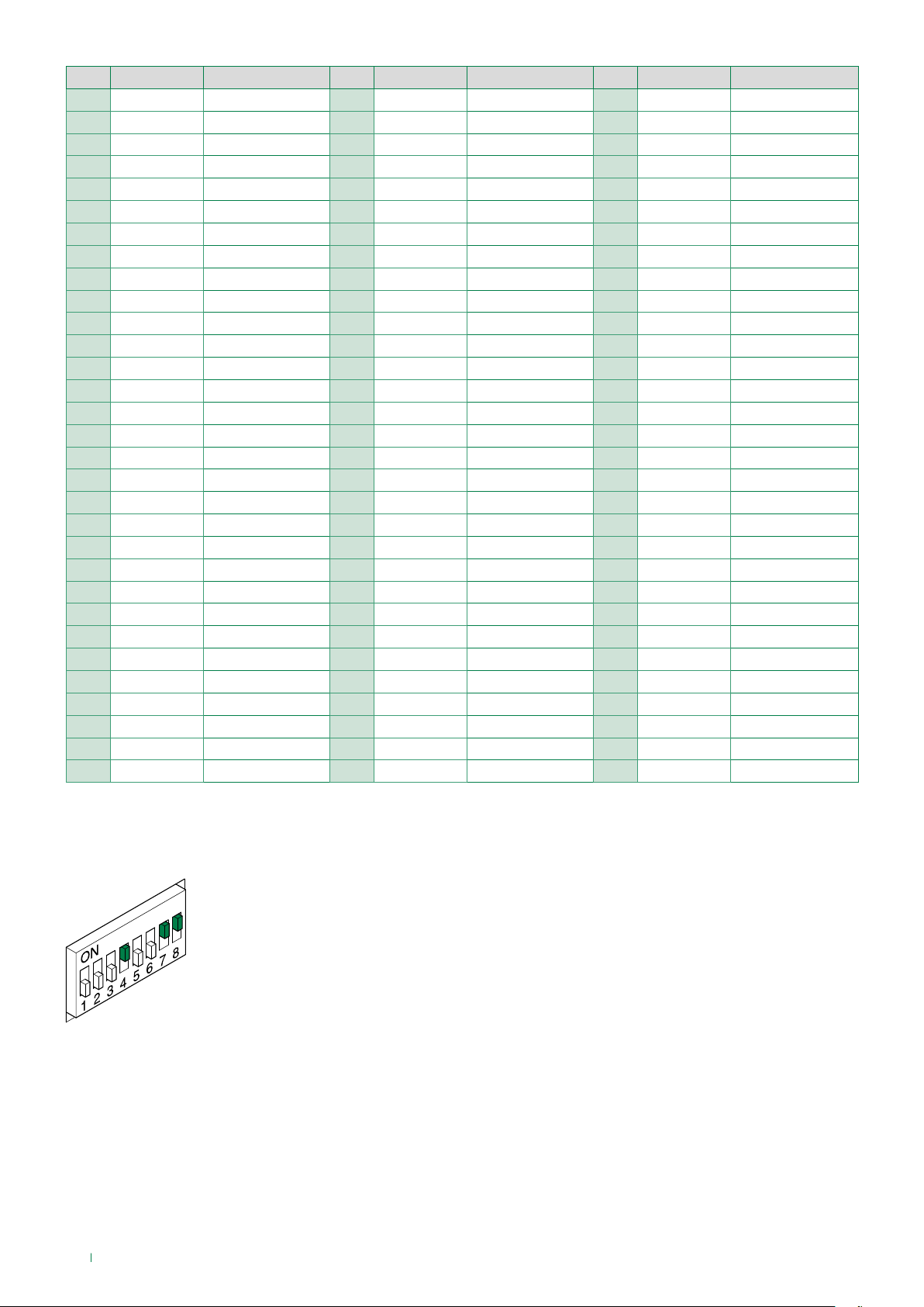
200 4,7,8
201 1,4,7,8
202 2,4,7,8
203 1,2,4,7,8
204 3,4,7,8
205 1,3,4,7,8
206 2,3,4,7,8
207 1,2,3,4,7.8
208 5,7,8
209 1,5,7,8
Code Dip switch ON Name
210 2,5,7,8
211 1,2,5,7,8
212 3,5,7,8
213 1,3,5,7,8
214 2,3,5,7,8
215 1,2,3,5,7.8
216 4,5,7,8
217 1,4,5,7,8
218 2,4,5,7,8
219 1,2,4,5,7.8
220 3,4,5,7,8
221 1,3,4,5,7.8
222 2,3,4,5,7.8
223 1,2,3,4,5,7,8
224 6,7,8
225 1,6,7,8
226 2,6,7,8
227 1,2,6,7,8
228 3,6,7,8
229 1,3,6,7,8
230 2,3,6,7,8
231 1,2,3,6,7.8
232 4,6,7,8
233 1,4,6,7,8
234 2,4,6,7,8
235 1,2,4,6,7.8
236 3,4,6,7,8
237 1,3,4,6,7.8
238 2,3,4,6,7.8
239 1,2,3,4,6,7,8
*240 5,6,7,8
*NOTE: code 240 is reserved for the porter switchboard
EXAMPLE: dip switch setting for code 200
8
Page 9
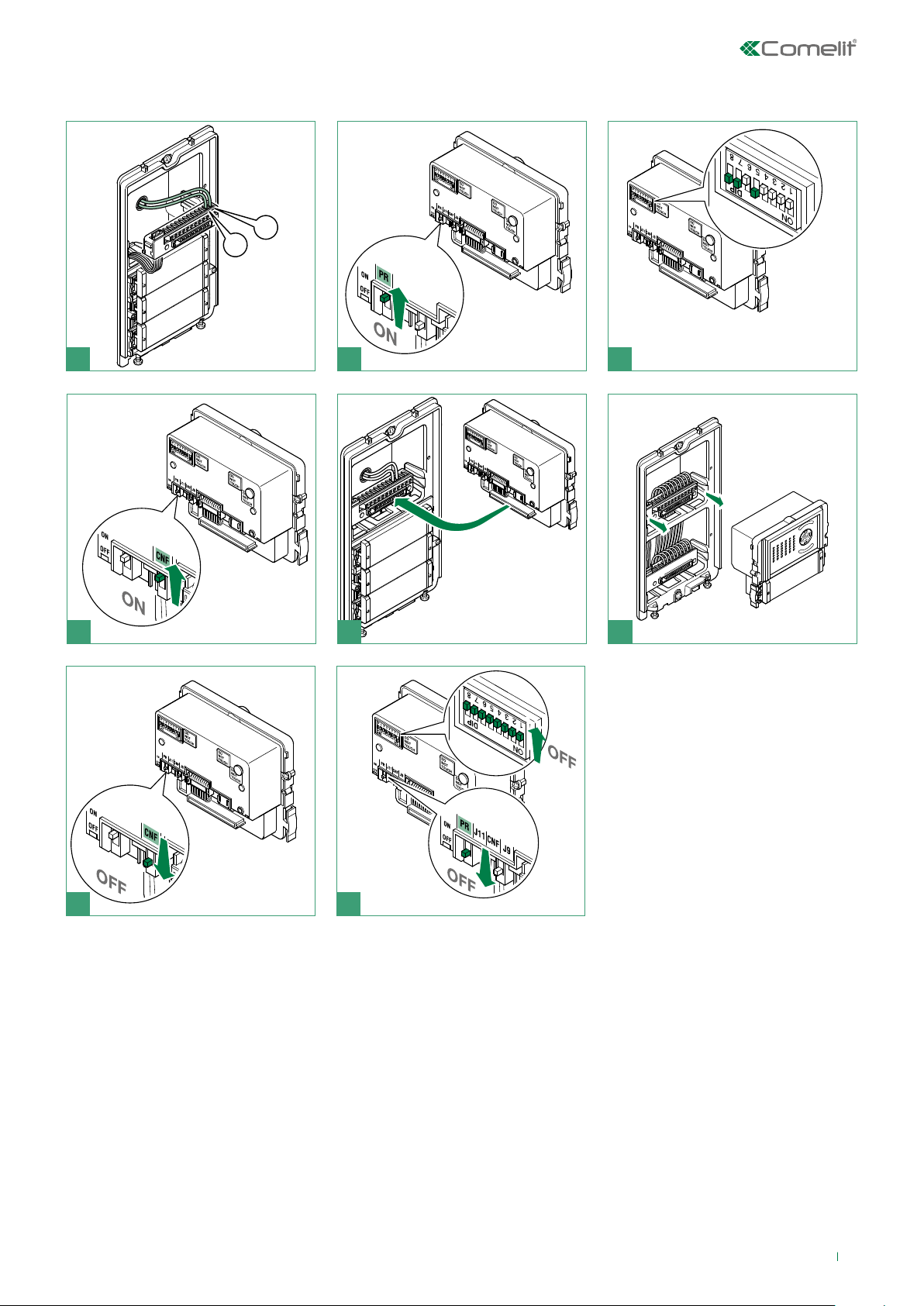
Special programmes
L
L
1
Set the dip switches for the
function you wish to program, see
2
the table on page 10.
3
64 5
1
2
87
9
Page 10

CODE DIP SWITCHES ON
213 1,3,5,7,8
212 3,5,7,8
195 1,2,7,8
196 3,7,8
197 1,3,7,8
198 2,3,7,8
199 1,2,3,7,8
206 2,3,4,7,8
207 1,2,3,4,7.8
211 1,2,5,7,8
215 1,2,3,5,7.8
216 4,5,7,8
217 1,4,5,7,8
218 2,4,5,7,8
219 1,2,4,5,7.8
220 3,4,5,7,8
221 1,3,4,5,7.8
222 2,3,4,5,7.8
FUNCTIONS
De-misting heating element
OFF (default)
ON
Audio-visal messages
Hebrew
Polish
Catalan
Galician
Basque
Danish
Norwegian
Swedish
Italian
French
Spanish
Dutch
Greek
English
German
Portuguese
202 2,4,7,8
203 1,2,4,7,8
208 5,7,8
209 1,5,7,8
210 2,5,7,8
214 2,3,5,7,8
227 1,2,6,7,8
228 3,6,7,8
229 1,3,6,7,8
230 2,3,6,7,8
231 1,2,3,6,7.8
245 1,3,5,6,7.8
246 2,3,5,6,7.8
247 1,2,3,5,6,7,8
Enables voice message (door opened warning) when the RTE contact is closed
Disables voice message (door opened warning) when the RTE contact is closed (default
setting)
Enables “awaiting reset time" on lock release command.
Disables “awaiting reset time" on lock release command (awaiting response time or talk
time will be activated).
visual messages only
OFF (default)
Actuator command management
N.B. Art. 1256 in generic actuator mode must not be present in the system.
Actuator function on S serial line = enabled
Actuator function on S serial line = disabled (default)
Enabling C.NC.NO relay on actuator command: 2 secs.
Enabling C.NC.NO relay on actuator command: 4 secs.
Enabling C.NC.NO relay on actuator command: 8 secs.
Door lock
Door lock time: 2 secs. + disabling tone (default)
Door lock time: 4 secs.
Door lock time: 8 secs.
248 4,5,6,7,8
251 1,2,4,5,6,7,8
252 3,4,5,6,7.8
253 1,3,4,5,6,7,8
232 4,6,7,8
233 1,4,6,7,8
234 2,4,6,7,8
10
Door lock confirmation tone: enabled
Relay C.NC.NO in parallel to SE (default)
Lock-release always enabled (default)
Lock-release only enabled for user called
System functions
Awaiting response time: 60 secs.. (default)
Awaiting response time: 120 secs.
Awaiting response time: 30 secs.
Page 11
235 1,2,4,6,7.8
236 3,4,6,7,8
Talk time: 90 secs. (default)
Talk time: 180 secs.
237 1,3,4,6,7.8
238 2,3,4,6,7.8
239 1,2,3,4,6,7,8
240 5,6,7,8
243 1,2,5,6,7.8
244 3,5,6,7,8
208 5,7,8
209 1,5,7,8
249 1,4,5,6,7.8
250 2,4,5,6,7.8
0
255 1,2,3,4,5,6,7.8
254 2,3,4,5,6,7,8
Self-ignition: enabled (default)
Self-ignition: disabled
Confirmation tone on user call = enabled (default)
Confirmation tone on user call = disabled
Awaiting reset time: 10 secs. (default)
Awaiting reset time: 1 sec.
Reset after lock-release in audio: enabled (default)
Reset after lock-release in audio: disabled
Call transmission: single (default)
Call transmission: triple
System mode
Simplebus (default)
Simplebus Top (NO Art. 4680KC)
Restore default
11
Page 12

Power supply unit Art. 1210
1. 3. 4.2.
Dopo un cortocircuito,per ripristinare l'apparecchio,
interrompere l'alimentazione per circa 1 minuto.
To reset the operation after a short circuit,cut o mains
voltage for about 1 minute.
Apres un court circuit, pour remettre en fonction l'appareil,
interrompre l'alimentation pendant environs une minute.
INPUT/D'ENTREE
110V-240V
L
800mA
50-60Hz
N
ta=40°C
C US
257258
OUTPUT/SORTIE 34V 0.5A
R
1.2A 1'on/5'o
L1
L1
t.
Ar 1210
L2
L2
1. L N mains power input 110-240 V~
2. Terminal protection
3. L1 L1 main bus line output (34 V )
4. L2 L2 riser bus line input (34 V )
The building's electrical system must include an omnipolar mains switch (easily accessible) with contact
separation of at least 3mm to disconnect the power supply from the device.
12
Page 13

-L
+L
PR CNF
Consumption management
On systems with Art. 4681 and power supply unit Art. 1210, the maximum current available for the external
unit modules is 100mA.
Calculate the total power consumption of the modules in your system configuration using the Consumption
table.
If the total power consumption exceeds 100mA, connect a supplementary power supply unit (Art. 1595) to
the V+ and V- contacts of the external unit, as shown in the figure below (see the diagram S2W/MOD)
External unit module consumption table
Code Consumption
1172B LED bulb 8mA
with 1 bistable
3348B
3360B 45mA
SK9000I 50mA
SK9001I 50mA
ACM/R 60mA
ACM/500-2 60mA
3063D 8mA*
33400x 0mA
33401x 20mA
33402x 20mA
33410x 0mA
33411x 20mA
33412x 20mA
33436 / 33434 / 33433 20mA
3336x 20mA
3262S/1/2 / 3268S/1/2 0 mA*
3262S/0 / 3268S/0 0 mA
3064S 8mA*
3070S only with 1595 (see diagram on page 25)
3072S only with 1595 (see diagram on page 25)
3188S only with 1595 (see diagram on page 26)
* Add the consumption of bulb 1172B, if used.
relay active
with 2 bistable
relays active
A powered by
Art. 1210
30mA
60mA
80mA
+V
+L
-L
J11 J9
-V
B powered by
power supply unit
Art. 1595
Notes on maximum limit with the supplementary power
supply unit Art. 1595
with MAX 17 Art. 33436 / 33434 / 33433 supplementary
power supply unit Art. 1595 (see diagram on page. 20)
with MAX 17 Art. 33436 / 33434 / 33433 supplementary
power supply unit Art. 1595 (see diagram on page. 20)
MAX 30 pcs with supplementary power supply unit Art. 1595
(see diagram on page 22)
MAX 17 pcs with supplementary power supply unit Art. 1595
(see diagram on page 17)
MAX 30 pcs with supplementary power supply unit Art. 1595
(see diagram on page 24)
13
Page 14

Operating distances with Art. 1210
C
B
H
4681
1214/2C
1216
1210
A
1214/2C
1214/2C
C
B
H
4681
1214/2C
1216
1210
A
6700W
6701W
6701B
(MAX 4)
6721W
(MAX 4)
6700W
6701W
6701B
1214/2C
1214/2C
6801W
6601W
6721W
6801W
6601W
6601W
6601W
(MAX 3)
D
6801W
1212/B
(MAX 1)
Distances valid for articles: 6700W, 6701W, 6701B, 6721W, 6801W
A MAX B MAX C MAX H MAX D MAX Art. 1216
Comelit Art. 4577/4579 1 mm2
(Ø 1.2 mm AWG 17)
UTP5 cat. 5 0.2 mm2
(Ø 0.5 mm AWG 24)
0.28 mm2
(Ø 0.6 mm AWG 23)
0.5 mm2
(Ø 0.8 mm AWG 20)
1 mm2
(Ø 1.2 mm AWG 17)
1.5 mm2
(Ø 1.4 mm AWG 15)
*UTP5 cat. 5 0.2 mm2
(Ø 0.5 mm AWG 24)
MULTI PAIR CABLE
(850 feet)
(260 feet)
(328 feet)
(460 feet)
(656 feet)
(260 feet)
260 m
80 m
100 m
140 m
200 m
80 m
130 m
(425 feet)
40 m
(130 feet)
50 m
(164 feet)
70 m
(230 feet)
100 m
(328 feet)
40 m
(130 feet)
130 m
(425 feet)
40 m
(130 feet)
50 m
(164 feet)
70 m
(230 feet)
100 m
(328 feet)
40 m
(130 feet)
50 m
(164 feet)
30 m
(98 feet)
30 m
(98 feet)
30 m
(98 feet)
40 m
(130 feet)
30 m
(98 feet)
100 m
(328 feet)
/
10 m
(32.5 feet)
25 m
(82 feet)
50 m
(164 feet)
100 m
(328 feet)
2
2
2
1
1
*UTP cable with multi-cable connection: FOLLOW THE COLOURS SHOWN IN THE DIAGRAM!
GREEN
GREEN / WHITE
ORANGE / WHITE
ORANGE
BLU / WHITE
BROWN / WHITE
BROWN
BLU
260 m
(850 feet)
130 m
(425 feet)
130 m
(425 feet)
14
50 m
(164 feet)
/
2
Page 15

Distances valid for Art. 6601W
A MAX B MAX C MAX H MAX D MAX Art. 1216
Comelit Art. 4577/4579 1 mm2
(Ø 1.2 mm AWG 17)
160 m
(525 feet)
70 m
(230 feet)
90 m
(295 feet)
30 m
(98 feet)
100 m
(328 feet)
2
UTP5 cat. 5 0.2 mm2
(Ø 0.5 mm AWG 24)
0.28 mm2
(Ø 0.6 mm AWG 23)
0.5 mm2
(Ø 0.8 mm AWG 20)
1 mm2
(Ø 1.2 mm AWG 17)
1.5 mm2
(Ø 1.4 mm AWG 15)
*UTP5 cat. 5 0.2 mm2
(Ø 0.5 mm AWG 24)
MULTI PAIR CABLE
GREEN
GREEN / WHITE
ORANGE / WHITE
ORANGE
BLU
BLU / WHITE
BROWN / WHITE
BROWN
80 m
(263 feet)
90 m
(295 feet)
110 m
(360 feet)
140 m
(460 feet)
60 m
(197 feet)
240 m
(786 feet)
40 m
(130 feet)
40 m
(130 feet)
50 m
(164 feet)
70 m
(230 feet)
30 m
(98 feet)
120 m
(393 feet)
40 m
(130 feet)
50 m
(164 feet)
60 m
(197 feet)
70 m
(230 feet)
30 m
(98 feet)
120 m
(393 feet)
30 m
(98 feet)
30 m
(98 feet)
30 m
(98 feet)
30 m
(98 feet)
30 m
(98 feet)
60 m
(197 feet)
/
10 m
(32.5 feet)
25 m
(82 feet)
50 m
(164 feet)
100 m
(328 feet)
/
2
2
1
1
2
*UTP cable with multi-cable connection: FOLLOW THE COLOURS SHOWN IN THE DIAGRAM!
Maximum system expansion
Devices
6601W
1229A
1229
Max. number of monitors (per
Type) that can be connected to
the system
Maximum number of main
internal units powered from
the riser
Maximum number of main
internal units that can be
powered from Art. 1212/B
Maximum number of internal
units (including call repetition
devices) with the same user
code
Call repetition devices that can
be used
6700W 6701W 6701B
100 100 90 100
1 1 1 1
/ / 1 1
4 4 3 4
1229A 1229A
6721W
6801W
1229A
1229
15
Page 16

Wiring diagrams
6601W/BM
6801W/BM
Video entry phone system with 1 external unit Art. 4681: system commissioning/voltage test with system at rest.
1
1216
LL
C
2628/
2638
L L
C
F
P
C
P C S
F
P
C
S+S
IN
IN
F
F
1
L L
2
1 2
-
P
P
+
-
32-34 Vdc
1214/2C
L
L
OUT
OUT
LM
L
LM
INLIN
S
33
+
-
1214/2C
L
L
OUT
OUT
LM
LINL
LM
IN
L L
C
C
S+S
F
F
P
P
-
1214/2C
L
L
OUT
OUT
LM
LINL
LM
IN
6801W/
6228B
6228W
SW1
S2 S1
6721W
6721W/BM
6700W
6701W
6701B
1 2 3 4 5 6
C
C
F
F
1
2
LL
P
P
1214/2C
L
L
OUT
OUT
LM
LINL
LM
IN
C
C
F
1
+
LL
-
P
IN21IN
S+S
F
2
-
P
6601W/
1214/2C
L
L
OUT
OUT
LM
LINL
LM
IN
110-240V
L
N
L2
L2
L1
L1
34 Vdc
34 Vdc
1210
32-34 Vdc
VV
+
4681
J1
LL
J2
J2
33433/33434/33436
(MAX 5 MODULES)
C
SE
SE
O
NC
+
-
M
R
G
D
T
N
NO
O
-
E
D
J1
Local lock release button.
For configurations other than those indicated in the diagram, refer to the “CONSUMPTION
TABLE” on page 13
16
S2W/039MI
Page 17

Wiring diagram for system with external unit 4681 and supplementary power supply unit Art. 1595 (for
N° 5
N° 6
N° 17
maximum number of expansion modules).
110-240V
SE
SE
+
-
4681
1210
C
O
NC
M
J9 J11
L
N
L2
L2
L1
L1
1595
+
-
120-230 V
R
G
D
VV
T
N
NO
O
+
-
E
D
J1
LL
J2
J1
J2
33433
33434
33436
J1
J2
33433
33434
33436
J1
J2
33433
33434
33436
J1
J2
33433
33434
33436
J1
J2
33433
33434
33436
J1
J2
33433
33434
33436
J1
J2
33433
33434
33436
Local lock release button.
NOTA BENE
Diagram applies to systems with up to 17 Art. 33433 / 33434 / 33436.
S2W/MOD
17
Page 18

300(1-12)XVB
Wiring diagram for system with digital call module Art. 3360B
Local lock release button.
110-240V
SE
SE
+
-
1210
C
O
NC
M
NO
L
N
L2
L2
L1
L1
R
G
D
VV
T
N
O
+
-
E
D
4681/
J1
LL
J2
G
P
485
485 24
NDGR
S
+
D
D
-
3360B
Vac24Vac
J1
J2
1621
S2W/QNP
Wiring diagram for system with external unit Art. 300(1-12)XVB
110-240V
SE
SE
+
-
1210
C
O
M
L
N
L2
L2
L1
L1
G
D
N
NO
NC
O
D
R
VV
T
E
LL
+
-
18
S2W/001X Local lock release button.
Page 19

Wiring diagram for system with electronic digital key module Art. 3348B
NO
L
N
L2
L2
L1
L1
R
G
D
N
O
D
VV
T
-
E
LL
+
J1
J2
J1
J2
33433/33434/33436
C
2NO2NC2C1NO1NC1
~+~
-
R
AL
+
C
-
K
K
3348B
110-240V
1210
C
SE
SE
O
NC
+
-
M
4681 - 1621
(MAX 2 MODULES)
Local lock release button.
For configurations other than those indicated in the diagram, refer to the “CONSUMPTION TABLE” on page 13
D D
+
-
S2W/01S/PCI
19
Page 20

Wiring diagram for system with electronic digital key module Art. 3348B and supplementary power
N°17
supply unit Art. 1595 (for maximum number of expansion modules).
110-240V
1210
C
SE
SE
O
NC
+
-
M
4681 - 1621
L
N
L2
L2
L1
L1
+
-
R
G
D
VV
T
N
NO
O
E
D
LL
+
-
J1
J2
33433
33434
33436
120-230 V
J1
J2
1595
J1
J2
33433
33434
33436
J9 J11
Local lock release button.
NOTA BENE
Diagram applies to systems with up to 17 Art. 33433 / 33434 / 33436.
33433
33434
33436
C
2NO2NC2C1NO1NC1
~+~
R
AL
C
D D
-
+
-
K
K
+
-
3348B
S2W/PCIA
20
Page 21

Wiring diagram for system with single-plate entrance panel Art. 3063D
N°6
3063D
110-240V
1210
C
SE
SE
O
NO
NC
+
-
M
4681 - 1621
CV2
L
N
L2
L2
L1
L1
J1
R
G
D
VV
T
N
O
+
-
E
D
J1
LL
J2
J1
V
J2
S C
J2
+
P2P
1
P3P4P5P6P7P
8
-
3063D
1172B
N°1
1172B
N°6
(MAX 6)
J1
V
S C
+
P2P
-
1
N°1
P3P4P5P6P7P
3063D
8
(MAX 6 MODULES)
Local lock release button.
Use the cable included in Art. 1250IV, Art. 1250IA
NOTA BENE
Diagram applies to systems with up to 6 Art. 3063D, plus up to 6 Art. 1172B.
Use bulb Art. 1172B for nameplate lighting. The lamp is polarised.
For configurations other than those indicated in the diagram, refer to the “CONSUMPTION TABLE” on page 13
S2W/MOD2A
21
Page 22

Wiring diagram for system with single-plate entrance panel Art. 3063D with supplementary power
N°30
supply unit Art. 1595 (for maximum number of expansion modules).
3063D
110-240V
1210
C
SE
SE
O
NO
NC
+
-
M
4681 - 1621
J9 J11
CV2
L
N
L2
L2
L1
L1
+
-
R
G
D
VV
T
N
O
+
-
E
D
J1
LL
J2
120-230 V
J1
J2
J1
J2
1595
V
S C
+
P2P
1
P3P4P5P6P7P
8
-
3063D
1172B
1172B
J1
V
S C
+
P2P
-
1
N°1
P3P4P5P6P7P
3063D
8
Local lock release button.
Use the cable included in Art. 1250IV, Art. 1250IA
NOTA BENE
Diagram applies to systems with up to 30 Art. 3063D, plus up to 30 Art. 1172B.
Use bulb Art. 1172B for nameplate lighting. The lamp is polarised.
22
S2W/MOD2
Page 23

Wiring diagram for system with Vandalcom entrance panel and conventional button modules Art.
3064S
3064S
110-240V
1210
C
SE
SE
O
NO
NC
+
-
M
1621+3262S
4681+3268S
L
N
L2
L2
L1
L1
R
G
D
VV
T
N
O
+
-
E
D
J1
LL
J2
J1
S
-
J2
3064S
J1
V
C
+
S
-
J2
3064S
J1
V
C
+
J2
V
S
-
+
J1
V
C
S
C
-
+
3064S
N°1 N°2 N°3 N°6
(MAX 6 MODULES)
CV3
3064S
N°6
1172B 1172B 1172B 1172B
Local lock release button.
Use the cable supplied with Art. 3262S, Art. 3268S
NOTA BENE
Diagram applies to systems with up to 6 Art. 3064S, plus up to 6 Art. 1172B.
Use bulb Art. 1172B for nameplate lighting. The lamp is polarised.
For configurations other than those indicated in the diagram, refer to the “CONSUMPTION TABLE” on page 13
(MAX 6)
S2W/MOD3A
23
Page 24

Wiring diagram for systems with Vandalcom entrance panel and conventional button modules Art.
1172B 1172B 1172B 1172B
3064S and supplementary power supply unit Art. 1595 (for maximum number of expansion modules).
110-240V
1210
C
SE
SE
O
NO
NC
+
-
M
1621+3262S
4681+3268S
L
N
L2
L2
L1
L1
G
N
D
J9 J11
1595
+
-
120-230 V
R
D
T
O
+
-
E
J1
VV
LL
J2
J1
S
-
J2
3064S
J1
V
C
+
S
-
J2
3064S
J1
V
C
+
J2
V
S
-
+
3064S
J1
V
C
S
C
-
+
3064S
N°1 N°2 N°3 N°30
CV3
3064S
Local lock release button.
Use the cable supplied with Art. 3262S, Art. 3268S
NOTA BENE
Diagram applies to systems with up to 30 Art. 3064S, plus up to 30 Art. 1172B.
Use bulb Art. 1172B for nameplate lighting. The lamp is polarised.
24
S2W/MOD3
Page 25

Wiring diagram for systems with digital call modules Art. 3070S and Art.3072S
3072S
2E7T000696
110-240V
1210
C
SE
SE
O
NO
NC
+
-
M
1621+3262S
4681+3268S
L
N
L2
L2
L1
L1
G
N
D
J9 J11
1595
+
-
120-230 V
R
D
T
O
-
E
J1
VV
J2
LL
+
12~12
VV
+
-
"V " BLUE
P
S
-
-
~
+ +
-
D
3070S
T
R
-
XR
12~12
VV
X
+
-
S
-
~
P
R X
D
DD
-
-
R-T
X
"S" YELLOW
"V+" BROWN
Local lock release button.
Use the cable 2E7T000696 supplied with Art. 3070S and Art. 3072S
S2W/DV1
25
Page 26

Wiring diagram for systems with Vandalcom electronic key module Art. 3188S
1210
L
N
110-240V
L2
L2
L1
L1
3188S
-
AL
CK
+
~
-
~
-
AC
OUT
+
-
+
-
D
D
PGM
NC2
C1
NO1
-
RK
NC1
C2
NO2
LL
O
D
E
T
R
NO
SE
-
SE
+
NC
C
O
M
+
VV
-
G
N
D
1621+3262S
4681+3268S
C
V
+
-
S
3064S
J2
J1
J1
J2
3064S
J9 J11
-
+
1595
120-230 V
CV3
Local lock release button.
Use the cable supplied with Art. 3262S, Art. 3268S
S2W/016ECA
26
Page 27

Wiring diagram for systems with Art. SK9015 for connection of readers Art. SK9000I and Art. SK9001I
1
SK9015
1216
LL
C
6721W
6721W/BM
C
F
F
1
LL
2
P
P
1214/2C
L
L
OUT
OUT
LM
LINL
LM
IN
110-240V
L
N
L2
L2
L1
L1
1210
LL
V
V
+
-
+
-
12V12V
DD
+
+
-
SK9000I
SK9001I
DD
NC
-
C NO AoAiPB G
RTE
C
SE
SE
O
NO
NC
+
-
M
R
G
D
VV
T
N
O
+
-
E
D
4681
1621
J1
LL
J2
J1
J2
33433/33434/33436
(MAX 5 MODULES)
For configurations other than those indicated in the diagram, refer to the “CONSUMPTION TABLE” on page 13
SK/AACI2
27
Page 28

Use of external unit relay on lock release or actuator command
12/24V
JP1
230 V
1210
12V/24V
AC-DC
10A MAX
“C.NC.NO relay activation on actuator command: 2 secs.”
f Set dip switches in permanent mode as shown in figure (Dip switch 8
ON, Dip switches 1,2,3,4,5,6,7 OFF)
Local lock release button.
Use of RC network for lock filter on relay contacts
SE
-
SE
C
O
NO
NC
+
M
R
G
D
N
O
D
VV
T
-
E
LL
+
4681/
1621
S2W/RTNP
Wiring diagram with safety lock
Local lock release button.
28
On C. NO contacts. On C. NC contacts. Excluded: voltage-free
contact
4681
1210
LL
J2
J2
J1
J1
33436
SE
-
AC/DC
SE
O
+
M
C
NO
NC
R
G
D
VV
T
N
O
+
-
E
D
S2W/QNP
Page 29

1
33433/33434/33436
(MAX 5 MODULES)
Wiring diagrams for system with switching device Art. 1404
System with Art. 1210: switching device in STANDARD mode and 2 inputs
1216
LL
C
C
S+S
IN
IN
F
F
2
L L
1
1 2
-
P
P
+
-
6801W/
6801W/BM
6721W
6721W/BM
6700W
6701W
6701B
2628/
2638
1 23 4 5 6
L L
1214/2C
L
L
OUT
OUT
LM
L
LM
INLIN
C
C
P C S
S
F
F
33
+
P
LL
-
P
1214/2C
L
L
OUT
OUT
LM
LINL
LM
IN
1214/2C
L
L
OUT
OUT
LM
LINL
LM
IN
C
C
F
F
2
1
P
P
L L
C
C
S+S
F
F
-
P
P
6228B
6228W
SW1
S2 S1
1214/2C
L
L
OUT
OUT
LM
LINL
LM
IN
C
C
IN21IN
S+S
F
F
2
1
+
LL
-
-
P
P
6601W/
6601W/BM
1214/2C
L
L
OUT
OUT
LM
LINL
LM
IN
1404
LP
IN
OUT
JP1
A
ON
S3
110-240V
B
4321
L
N
L2
L2
L1
L1
1210
C
SE
SE
O
NC
+
-
M
R
G
D
T
N
NO
O
-
E
D
J1
VV
LL
J2
+
1621
110-240V
SE
SE
+
-
1210
C
O
M
MIN
MAX
ON
LMLMLSLSLP
85 764321ON85 764321
S2S1
L
N
L2
L2
L1
L1
J1
VV
+
4681
J1
LL
J2
J2
33433/33434/33436
(MAX 5 MODULES)
R
G
D
T
N
NO
NC
O
-
E
D
Local lock release button.
For configurations other than those indicated in the diagram, refer to the “CONSUMPTION TABLE” on
page 13
J1
J2
S2W/004MI
29
Page 30

1
6721W
6721W/BM
6721W
6721W/BM
System with Art. 1210: switching device in STANDARD mode, 1 main input and 2 secondary inputs
1216
LL
C
6700W
6701W
6701B
2628/
2638
C
S+S
IN
IN
F
F
1
L L
2
1 2
-
P
P
+
-
1214/2C
C
C
P C S
S
F
F
L L
12 3 4 5 6
33
+
P
LL
-
P
C
C
F
F
1
2
P
P
L
L
OUT
OUT
LM
L
LM
INLIN
1214/2C
L
L
OUT
OUT
LM
LINL
LM
IN
L L
C
C
S+S
F
F
-
P
P
1214/2C
L
L
OUT
OUT
LM
LINL
LM
IN
1214/2C
L
L
OUT
OUT
LM
LINL
LM
IN
C
C
IN21IN
S+S
F
F
2
1
+
LL
-
-
P
P
1214/2C
L
L
OUT
OUT
LM
LINL
LM
IN
6228B
6228W
SW1
S2 S1
6801W/
6801W/BM
6601W/
6601W/BM
110-240V
SE
SE
+
-
1210
C
O
M
MIN MAX
ON
S2S1
L
N
L2
L2
L1
L1
LMLMLSLSLPINLP
85 764321ON85 764321
1404
OUT
JP1
A
ON
S3
110-240V
B
4321
L
N
L2
L2
L1
L1
1210
J1
VV
+
4681
J1
LL
J2
J2
33433/33434/33436
(MAX 5 MODULES)
R
G
D
T
N
NO
NC
O
-
E
D
30
VV
+
4681
J1
LL
J2
J2
33433/33434/33436
(MAX 5 MODULES)
C
SE
SE
O
NC
+
-
M
R
G
D
T
N
NO
O
-
E
D
J1
Page 31

2
6601W/BM
6721W
6801W/BM
6721W/BM
6700W
6701W
6701B
2628/
2638
1216
LL
C
C
S+S
IN
IN
F
F
1
L L
2
1 2
-
P
P
+
-
6801W/
1214/2C
C
C
P C S
S
F
F
L L
12 3 4 5 6
33
+
P
LL
-
P
C
C
F
F
1
2
P
P
L
L
OUT
OUT
LM
L
LM
INLIN
1214/2C
L
L
OUT
OUT
LM
LINL
LM
IN
1214/2C
L
L
OUT
OUT
LM
LINL
LM
IN
L L
C
C
S+S
F
F
-
P
P
6228B
6228W
SW1
S2 S1
1214/2C
L
L
OUT
OUT
LM
LINL
LM
IN
110-240V
1210
C
C
IN21IN
S+S
F
F
2
1
+
LL
-
-
P
P
6601W/
1214/2C
L
L
OUT
OUT
LM
LINL
LM
IN
MIN MAX
ON
S2S1
L
N
L2
L2
L1
L1
LMLMLSLSLPINLP
85 764321ON85 764321
1404
OUT
JP1
A
B
ON
4321
S3
VV
+
1621
J1
LL
J2
J2
33433/33434/33436
(MAX 5 MODULES)
C
SE
SE
O
NC
+
-
M
R
G
D
T
N
NO
O
-
E
D
J1
Local lock release button.
WARNING! Separate switching devices must manage code ranges which are not overlapping.
For configurations other than those indicated in the diagram, refer to the “CONSUMPTION
TABLE” on page 13
S2W/005MI
31
Page 32

System with Art. 1210: switching devices in STANDARD mode and 8461 KIT in cascade
8461I
NO
SE
-
SE
+
NC C
1209
L
N
110-240V
L2
L2
L1
L1
ON
+
-
LL
6601W/
6601W/BM
C
6601W/
6601W/BM
C
IN21IN
S+S
F
F
2
1
+
LL
-
-
P
P
ON
ON
85 764321
1234 675 8
S2S1
110-240V
1209
8461I
110-240V
1210
MAX
MIN
ON
ON
85 764321
L
N
L2
L2
L1
L1
R
C
SE
SE
NO
NC C
+
-
D
T
O
LL
O
E
M
LMLMLSLSLP
85 764321
S2S1
1404
JP1
LP
IN
OUT
A
B
ON
4321
S3
4893
L
N
L2
L2
L1
L1
J1
C
SE
SE
O
NC
+
-
M
R
G
D
T
N
NO
O
E
D
J1
VV
LL
+
-
4681
J2
J2
33433/33434/33436
(MAX 5 MODULES)
Local lock release button.
# For call address programming, please refer to the full manual for Art. 4893
For configurations other than those indicated in the diagram, refer to the “CONSUMPTION TABLE” on page 13
32
Page 33

B
6601W/
6601W/BM
C
C
IN21IN
S+S
F
F
2
1
+
LL
-
-
P
P
ON
ON
85 764321
1234 675 8
S2S1
6601W/
6601W/BM
C
C
IN21IN
S+S
F
F
2
1
+
LL
-
-
P
P
ON
ON
85 764321
1234 675 8
S2S1
110-240V
L
N
L2
L2
L1
L1
1209
SE
SE
NC C
+
-
8461I
MAXMIN
ON
ON
85 764321
LMLMLSLSLP
85 764321
S2S1
1404
JP1
LP
IN
OUT
A
B
ON
4321
S3
110-240V
L
N
L2
L2
L1
L1
MAXMIN
ON
ON
85 764321
LMLMLSLSLP
85 764321
S2S1
1404
JP1
LP
IN
OUT
A
ON
4321
S3
1209
R
C
D
T
NO
O
LL
O
E
M
SE
SE
NO
NC C
+
-
4893
2
8461I
R
C
D
T
O
LL
O
E
M
4893
30
IK/EN/006QC
33
Page 34

System with Art. 1210: switching devices in STANDARD mode, branched 8461 KIT
6601W/BM
110-240V
6801W/BM
110-240V
6801W/
6601W/
+
L L
-
110-240V
1209
SE
SE
-
8461X
+
LL
C
F
P
ON
S1
L
N
L2
L2
L1
L1
NO
NC C
+
-
C
S+S
IN
IN
F
1
2
1 2
-
P
ON
85 764321
1234 675 8
S2
MAX
MIN
ON
ON
R
C
D
T
O
LL
O
E
M
LMLMLSLSLP
85 764321
85 764321
S2S1
1404
LP
IN
OUT
JP1
A
B
ON
4321
S3
1216
LL
L
L
OUT
OUT
1214/2C
LM
L
LM
INLIN
L
L
OUT
OUT
LM
1214/2C
L
LM
INLIN
MAX
MIN
ON
ON
LMLMLSLSLP
85 764321
85 764321
S2S1
4893
3
6700W
6701W
6701B
12 3 45 6
C
C
F
F
1
2
LL
P
P
ON
ON
85 764321
1234 675 8
S1
S2
1404
LP
IN
OUT
JP1
A
B
ON
4321
S3
SE
SE
NO
NC C
+
-
L
N
L2
L2
L1
L1
1209
R
C
D
T
O
LL
O
E
M
4893
4
8461M
C
C
IN21IN
S+S
F
F
2
1
-
P
P
ON
ON
85 764321
1234 675 8
S2S1
6721W
6721W/BM
C
C
F
F
2
1
LL
P
P
ON
ON
85 764321
1234 675 8
S1
S2
110-240V
1209
8461I
MAX
MIN
ON
ON
L
N
L2
L2
L1
L1
R
C
SE
SE
NO
NC C
+
-
D
T
O
LL
O
E
M
LMLMLSLSLP
85 764321
85 764321
S2S1
1404
LP
IN
OUT
JP1
A
B
ON
4321
S3
L
L
OUT
OUT
1214/2C
LM
L
LM
INLIN
L
L
OUT
OUT
LM
1214/2C
L
LM
INLIN
MAX
MIN
ON
ON
LMLMLSLSLP
85 764321
85 764321
S2S1
4893
1210
L
N
L2
L2
L1
L1
110-240V
1404
LP
IN
OUT
JP1
A
B
ON
4321
S3
SE
SE
NO
NC C
+
-
L
N
L2
L2
L1
L1
1209
R
C
D
T
O
LL
O
E
M
4893
2
8461V
C
SE
SE
O
+
-
M
R
G
D
VV
T
N
NO
NC
D
LL
O
+
-
E
4681
J2
J2
33433/33434/33436
(MAX 5 MODULES)
J1
J1
Local lock release button.
For configurations other than those indicated in the diagram, refer to the “CONSUMPTION TABLE” on
page 13
# For call address programming, please refer to the full manual for Art. 4893
34
IK/EN/005QC
Page 35

Wiring digram for systems with camera module Art. 1409
1
6601W/BM
6721W
6721W/BM
6801W/BM
System Art. 1210: remote camera module Art. 1409 in generic actuator mode
1216
LL
C
C
S+S
IN
IN
F
F
1
L L
2
1 2
-
P
P
+
-
6801W/
6700W
6701W
6701B
2628/
2638
1214/2C
C
C
P C S
S
F
F
L L
33
+
-
P
P
C
C
F
F
1
2
LL
P
12 3 4 5 6
P
110-240V
L
N
L2
L2
L1
L1
1210
L
L
OUT
OUT
LM
L
LM
INLIN
1214/2C
L
L
OUT
OUT
LM
LINL
LM
IN
1214/2C
L
L
OUT
OUT
LM
LINL
LM
IN
1214/2C
L
L
OUT
OUT
LM
LINL
LM
IN
1214/2C
L
L
OUT
OUT
LM
LINL
LM
IN
G
I
LLL
~ ~
OUTLOUT
IN IN
NDAN
+
-
V S32SV2S11V
3
L L
1409
LL
-
C
C
S+S
F
F
P
P
+
ON
1234 675 8
-
C
C
F
P
IN21IN
S+S
F
2
1
-
P
6228B
6228W
SW1
S2 S1
6601W/
1200
230V~
12V~
VV
+
4681
J1
LL
J2
J2
33433/33434/33436
(MAX 5 MODULES)
C
SE
SE
O
NC
+
-
M
R
G
D
T
N
NO
O
-
E
D
J1
Local lock release button.
# Requires separate power supply.
For configurations other than those indicated in the diagram, refer to the “CONSUMPTION TABLE” on
page 13
S2W/002MI
35
Page 36

1st edition 07/2016
code 2G40001766
www.comelitgroup.com
Via Don Arrigoni, 5 - 24020 Rovetta (BG) - Italy
 Loading...