


RF500A Gateway System Manual |
|
Contents |
|
RF500 System Components............................................................................................................................................. |
4 |
RF500A Gateway................................................................................................................................................. |
4 |
RF500 Transmitters............................................................................................................................................. |
5 |
RF512 Temperature Transmitter............................................................................................................. |
5 |
RF512M Temperature Transmitter Backbone Option.............................................................................. |
5 |
RF513 Temperature and Humidity Transmitter........................................................................................ |
5 |
RF513M Temperature and Humidity Transmitter Backbone Option........................................................ |
5 |
RF515 Analog Input Transmitter and RF515A Connection Box.............................................................. |
5 |
RF516 Precision Temperature Transmitter.............................................................................................. |
6 |
Optional Accessories........................................................................................................................................... |
6 |
Know your Gateway............................................................................................................................................. |
7 |
RF500A Front Panel Indicators............................................................................................................... |
7 |
Bottom Connections................................................................................................................................ |
8 |
Alarm Outputs......................................................................................................................................... |
9 |
Side Switches and Indicators.................................................................................................................. |
9 |
Know your Transmitter....................................................................................................................................... |
10 |
Transmitter Display................................................................................................................................ |
12 |
Safety Information........................................................................................................................................................... |
13 |
Warning.............................................................................................................................................................. |
13 |
WEEE................................................................................................................................................................ |
14 |
RF500 Wireless Monitoring System Overview................................................................................................................ |
15 |
Gateway – Introduction...................................................................................................................................... |
15 |
Overview of RF500 Mesh Networking................................................................................................................ |
16 |
Meshing Transmitters and Backbone Transmitters............................................................................................ |
18 |
Automatic Data Retrieval (ADR)........................................................................................................................ |
18 |
1

Equipment Installation..................................................................................................................................................... |
19 |
Gateway Fixing.................................................................................................................................................. |
19 |
Transmitter Fixing.............................................................................................................................................. |
19 |
Mains Wiring...................................................................................................................................................... |
19 |
Ventilation.......................................................................................................................................................... |
19 |
Powering On and Off...................................................................................................................................................... |
20 |
Switch On........................................................................................................................................................... |
20 |
Gateway Switch OFF......................................................................................................................................... |
21 |
Gateway Reset.................................................................................................................................................. |
21 |
Transmitter Activation........................................................................................................................................ |
22 |
RF500ACONFIG Utility................................................................................................................................................... |
23 |
Installation of USB Drivers.................................................................................................................................. |
23 |
Obtain Comark USB Drivers.................................................................................................................. |
23 |
USB Driver Installation Instructions....................................................................................................... |
24 |
Installation of RF500ACONFIG.......................................................................................................................... |
25 |
Obtain RF500ACONFIG Utility............................................................................................................... |
25 |
RF500ACONFIG Installation Instructions.............................................................................................. |
26 |
Gateway Commissioning................................................................................................................................................ |
27 |
Requirements for Commissioning....................................................................................................................... |
27 |
Setting of Gateway IP Address using RF500ACONFIG..................................................................................... |
27 |
Viewing the Gateway Login Page...................................................................................................................... |
29 |
Setup of First Administrator................................................................................................................................. |
30 |
Gateway Language............................................................................................................................................ |
31 |
Gateway Name.................................................................................................................................................. |
31 |
GatewayClockSetup.......................................................................................................................................... |
31 |
Network Setup................................................................................................................................................... |
32 |
Network Details..................................................................................................................................... |
32 |
Gateway Programming and Use..................................................................................................................................... |
33 |
Gateway Specification – RF500A................................................................................................................................... |
34 |
2

Transmitters Specification............................................................................................................................................... |
35 |
Changing Lithium Battery on RF500 Series Transmitters............................................................................................... |
38 |
Battery Reordering............................................................................................................................................. |
38 |
Battery Change Procedure................................................................................................................................. |
38 |
Check for Transmitter Errors............................................................................................................................... |
40 |
Gateway Indication of Low Battery...................................................................................................................... |
40 |
Pinout and Wiring............................................................................................................................................................ |
41 |
Door Connector.................................................................................................................................................. |
41 |
Power Connector............................................................................................................................................... |
41 |
Lumberg Connector........................................................................................................................................... |
42 |
Gateway Relay Outputs..................................................................................................................................... |
42 |
FCC Approvals................................................................................................................................................................ |
43 |
Equipment Ratings.......................................................................................................................................................... |
44 |
Supply Voltage................................................................................................................................................... |
44 |
EnvironmentalConditions................................................................................................................................... |
44 |
Gateway Storage/Operating Conditions................................................................................................ |
44 |
RF51X Transmitter Operating Conditions.............................................................................................. |
44 |
RF51X Transmitter Storage Conditions................................................................................................. |
45 |
RF515 Maximum Input Conditions..................................................................................................................... |
45 |
Maintenance and Cleaning............................................................................................................................................. |
45 |
EC-Declaration of Conformity......................................................................................................................................... |
46 |
Transmitter Error Codes.................................................................................................................................................. |
47 |
Gateway Fault Conditions............................................................................................................................................... |
47 |
Appendix A - Setting a Fixed IP Address......................................................................................................................... |
48 |
Appendix B – Gateway Connection via RJ45 Cross-Over Ethernet Cable..................................................................... |
50 |
Definitions of Gateway Terminology................................................................................................................................ |
51 |
Glossary.......................................................................................................................................................................... |
54 |
3

RF500 System Components
RF500A Gateway
The RF500A Gateway is available in two variants:
• |
RF500A |
Standard |
• |
RF500AP |
Power over Ethernet enabled |
The actual Gateway model is indicated on the side label by a check mark adjacent to the model code.
The RF500A and RF500AP Gateway Kit consists of the following items.
• |
RF500A Gateway |
Part No. RF500A or RF500AP |
• |
Transmitter Activator |
Part No. RF525 |
• |
High Gain Antenna. |
Part No. RF504 |
•AC Adaptor
•Mains Lead with either UK, EU or US plug
RF500A
RF500AP
ON / OFF
Comark Instruments, 52 Hurricane way, Norwich, Norfolk, NR6 6JB. UK
Tel: 01603 (+44 1603) 256647 Email: service@comarkltd.com www.comarkltd.com
SERIAL No.
1 2 3 4
STATUS
Software and USB drivers are no longer provided on CD and can be downloaded free of charge from our website. See
RF500A Configure Utility for instructions on how to download the software and drivers.
Please confirm that the kit contents are all present and correct. If you believe any parts are missing or damaged please contact Comark or your local Distributor to arrange replacements.
4

RF500 Transmitters
RF500 Transmitters are available as follows. Each RF500 Transmitter is packed with a mounting bracket and 2-tie- wraps.
RF512 Temperature Transmitter
•Integral temperature sensor plus connectors for two external temperature sensors and an external door sensor
•External temperature range: –40°C to +125°C / -40°F to +257°F
RF512M Temperature Transmitter Backbone Option
•Integral temperature sensor plus connectors for two external temperature sensors and an external door sensor
•External temperature range: –40°C to +125°C / -40°F to +257°F
•Includes High Gain Antenna and RF520 AC mains adaptor
RF513 Temperature and Humidity Transmitter
•Integral temperature sensor, one integral humidity sensor and connector for an external door sensor
•Integral temperature range: –30°C to +70°C / -22°F to +158°F
•Humidity range: 10-90% RH
RF513M Temperature and Humidity Transmitter Backbone Option
•Integral temperature sensor, one integral humidity sensor and connector for an external door sensor
•Integral temperature range: –30°C to +70°C / -22°F to +158°F
•Humidity range: 10-90% RH
•Includes High Gain Antenna and RF520 AC mains adaptor
RF515 Analog Input Transmitter and RF515A Connection Box
•Two analog input channels, each capable of configuration as 0-1V, 0-10V or 4-20mA using RF515A connection box
5

RF516 Precision Temperature Transmitter
•Integral temperature sensor, and connector for one external temperature Pt100 sensor and an external door sensor
•External temperature range: –200°C to +400°C / -328°F to +752°F
Optional Accessories
RF520 |
AC adaptor for RF512, RF513 and RF516 |
RF502 |
Bridge. 0.5m lead to enable transmission through RF resistant barriers |
RF503 |
Bridge. 1.0m lead to enable transmission through RF resistant barriers |
RF515A |
2-Channel Terminal Box with 0.25m lead terminated with 6-Pin Lumberg Plug |
|
Includes two sets of 10R, 2K and 18K2 precision resistors |
RFJACK |
Alarm Output jack (2.5mm) |
RFALARM |
Alarm Output lead. 2m fig-8 wire terminated with 2.5mm jack |
6

Know your Gateway
RF500A Front Panel Indicators
ON POWER / FAULT ALARM
BATTERY
Figure 1 - Front Panel Indicators
There are four LEDs on the front of the Gateway:
ON |
Steady Blue |
The Gateway is running |
|
¼s on / ¼s off Blue |
Gateway is starting up |
POWER/BATTERY |
2s off / 2s on Blue |
Gateway is shutting down |
Steady Green |
External power is available |
|
|
Flashing Green |
Gateway is on and running off the battery pack |
FAULT |
Off |
Gateway is off and external power is not available |
Flashing Yellow |
Contact technical support from your local distributor or |
|
|
|
Comark Instruments. The Home Page may provide more |
ALARM |
|
information on possible faults |
Flashing Red |
An enabled alarm event has occurred |
7

Bottom Connections
C D E
B
A 


 A
A
Figure 2 - Rear view of RF500 Gateway
A.Cable clamps
B.12 VDC input
C.SW1 - Jack Socket for Relay Output 1
D.SW2 - Jack Socket for Relay Output 2
E.RJ45 Ethernet LAN Socket
8
Alarm Outputs
SW1 & SW2 are two switched outputs provided for connection to customer alarm indicators, via relay contacts with 24Vdc 500mA rating, configurable for either NO (Normally Open) or NC (Normally Closed). These are marked as SW1 and SW2, and are in the form of 2.5mm Jack Sockets. Plugs to fit these sockets can be ordered from Comark
Instruments using part number: RFJACK.


 With the Gateway switched OFF the relays are in a Normally Open condition, this may cause any
  equipment connected to the contacts to energise.
Side Switches and Indicators
RF500A
RF500AP
ON / OFF
Comark Instruments, 52 Hurricane way, Norwich, Norfolk, NR6 6JB. UK
Tel: 01603 (+44 1603) 256647 Email: service@comarkltd.com www.comarkltd.com
SERIAL No.
1 2 3 4
STATUS
Comark Instruments, PO Box 9090, Everett, WA 98206, USA
Tel: (503) 643 5204
Email: service@comarkUSA.com www.comarkUSA.com
FOR INDOOR USE ONLY DO NOT MOVE WHEN
IN OPERATION
AUX
MADE IN UK
|
Figure 3 – Left Hand Side View of Gateway |
ON/OFF |
Gateway Startup/Powerdown switch |
STATUS |
Diagnostic LEDs for technical support use |
AUX |
Reserved Switch |
9

Know your Transmitter
A B C
A. Alarm LED. Flashes red to indicate any one channel in alarm
B. Active LED. Flashes green to indicate external power detected
C. Infra-Red interface. For Comark use only
D. Antenna. (Do not remove whilst in operation)
E. Lashing eye - Four available
F. Internal temperature sensor
F
D
E
Figure 4 - Front view of RF512 Series Transmitter
10
A
B
C
Figure 5 - Connector view of RF512, RF515 & RF516 Transmitter
A.Lumberg Socket for Probe
B.Socket for Door & RF525 Activator (Dual function)
C.External DC adaptor socket
11
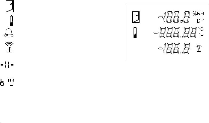
Transmitter Display
RF500 Transmitters all have a liquid crystal display as shown below. Only RF512 is capable of using all three display areas and annunciators.
Indicates that the door channel reads open. |
|
|
Indicates that the internal lithium battery requires replacement. |
|
INT |
|
|
|
Indicates an unacknowledged alarm on any channel. |
|
EXT1 |
|
|
|
When steady, indicates that the transmitter has logged |
|
|
onto the Gateway. |
|
EXT2 |
When flashing, indicates the transmitter is currently |
||
attempting transmission with the Gateway. |
|
|
Indicates that the sensor or probe is broken. |
|
Figure 6 - Transmitter Display |
 Indicates that the number to be displayed is too big to fit on the LCD

 E.g. 2000 cannot be shown on a “1999” digit area.
12

Safety Information
Under no circumstances may a user make any changes to the RF500A Gateway that would alter its performance. Any modification would void the CE compliance of the Gateway and may invalidate the warranty.
If the equipment is used in a manner not specified by Comark Instruments, then the protection provided by the equipment may be impaired.
No user serviceable parts are provided in RF500 Comark Wireless Monitoring Equipment. Contact Comark Instruments or your local distributor for all service requirements.
Warning
•Before connecting or disconnecting the antenna, ensure anti-static precautions are observed.
•Use only the FRIWO 12V AC adaptor; Type FW74010/12 as supplied; with the RF500A Gateway.
•Do not modify the RF500A Gateway AC adaptor in any way.
•Use only the PHIHONG, PSM11R-050 5V AC adaptor or FRIWO type FW7662/05 with RF500 Transmitters. It is supplied by Comark Instruments as three variants:
RF520 |
Transmitter AC adaptor with UK plug |
RF520/EU |
Transmitter AC adaptor with European style plug |
RF520/US |
Transmitter AC adaptor with North American style plug |
•Do not modify the AC adaptor in any way.
•RF500 Transmitters contain a C-size lithium cell. This cell must not be incinerated or subjected to temperatures in excess of 100°C / 212°F. Do not deform, mutilate, crush, pierce, disassemble, recharge or short circuit. Such abuse can result in loss of seal, and/or cell explosion. Also exposure to humid conditions for long periods should be avoided.
13

•Do not insert metal objects into connectors.
•Ensure the antenna is securely connected before powering the equipment. Internal damage may result otherwise.
•The Gateway and Transmitters have been designed to operate with the antenna supplied by Comark, and having a maximum gain of 7dBi. Antennas not supplied by Comark Instruments or having a gain of greater than 7dBi are strictly prohibited for use with this device. The required antenna impedance is 50 Ohms. If in doubt please contact Comark Instruments or your Distributor for advice.
WEEE
RF512, RF513, RF515 and RF516 Transmitters contain a non rechargeable lithium battery.
This battery must be disposed of in accordance with local regulations.
14

RF500 Wireless Monitoring System Overview
Gateway – Introduction
The RF500A Gateway is an embedded microprocessor device containing a radio module for RF communications to the measuring transmitters. The radio module uses a licence free band in the 2.4GHz spectrum. Comark
Instruments RF500 uses proprietary protocols over a standard IEEE 802.15.4 link. These protocols achieve reliable communication between the transmitters and the Gateway via self-healing mesh radio networks.
Data from measurements taken by the transmitters is stored on the RF500A Gateway in contrast to other systems which store their data on a PC using special software. For operating the RF500 system the only software required is a Web Browser such as Internet Explorer or Firefox. There is no requirement to install software on each user’s computer.
The Gateway contains sufficient data storage capacity for up to 10 years which can be automatically backed up to external storage using the built in shared drive backup method, or by manual request to generate and download a backup file via your web browser.
An external power adaptor provides the mains power for the Gateway. An internal Nickel-Metal-Hydride (Ni-Mh) rechargeable battery is included, this provides normal operation of the Gateway during power failure until the battery is exhausted, The Gateway then shuts down until power is restored.
Two relay connectors are provided for external alarms, Autodiallers/Klaxons etc. All other connections to the Gateway are disabled. See Figure 2 – Bottom View of Gateway for further details.
Emails for alarms will be instigated directly from the Gateway. It is also possible to send a text message alarm via email using a third party provider.
15

The Gateway can be either desk mounted or wall mounted. Wall mount keyhole slots are provided on the case. The external long range Antenna has variable orientation to suit vertical or horizontal mounting.
Four LEDs on the Gateway display current status of the system – On/Off, Power/Battery, Alarm indication, and Fault indicators.
Overview of RF500 Mesh Networking
The RF500 Wireless Monitoring System uses the IEEE 802.15.4 radio transmission standard to implement a radio mesh network.
A mesh network is comprised of the following devices:
•Gateway
•Mesh Transmitter
•Transmitter
On installation each transmitter is associated with a particular Gateway by serial number. Messages are transferred between transmitters and the Gateway using two-way communication with acknowledgement of successful message reception.
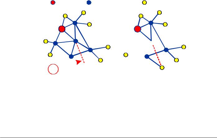
Transmitters which are physically close to their associated Gateway such as transmitter A in Figure 7 below, will most likely transmit directly to it. Others such as transmitter B which are further away rely on meshing transmitters to forward messages to and from the Gateway on their behalf.
The route taken by the message can vary depending on network load and link reliability. The ability to dynamically reconfigure the network is termed self-healing. In the figure below the self-healing ability is shown.
16
Gateway |
Mesh Transmitter |
Transmitter |
A |
|
A |
B 

 B
B
!

Data transfer interrupted |
Transmitter reroutes to |
transmitter continues to |
self-heal network and |
store data. |
transfers stored data. |
Figure 7 - A Typical Mesh Network
17
 Loading...