

Page 1

N9002 THERMOMETER
OPERATING INSTRUCTIONS
Page 2

CONTENTS
GENERAL INFORMATION ......................................................... 2
CALIBRATION, CERTIFICATION AND SERVICE ...................... 3
1. N9002 DESCRIPTION ................................................................ 4
2. N9002 WITH BIOCOTE® PROTECTION ................................... 4
3. OVERVIEW OF DISPLAY SYMBOLS ........................................ 5
4. THERMOMETER SETUP ........................................................... 6
5. SWITCHING ON AND OFF ......................................................... 8
6. N9002 OPERATION .................................................................... 8
7. CONNECTING PROBES ............................................................. 9
8. CARE OF THE THERMOMETER ................................................ 9
9. CHANGING THE BATTERIES .................................................... 10
10. N9002 SPECIFICATION .............................................................. 11
PAGE
1
Page 3
GENERAL INFORMATION
It is recommended that you read the safety and operation instructions
before using this instrument.
TO AVOID ELECTRIC SHOCK DO NOT ALLOW ANY PROBE OR
WARNING
SENSOR TO COME INTO CONTACT WITH LIVE ELECTRICAL
POWER CONDUCTORS WITH VOLTAGES IN EXCESS OF 30V AC
RMS OR 60V DC.
CAUTION
Temperature Measurement Probes
This precision instrument has been designed for use with the extensive
range of Comark temperature probes. The use of other probes may
impair the performance and accuracy of the instrument. Full details of
Comark probes and sensors can be obtained from Comark Customer
Support department or your local distributor.
Repeated sharp exing can break thermocouple probe leads. To
prolong lead life, avoid sharp bends or kinks in the leads, especially
near the connector.
This instrument is manufactured in accordance with
the Company’s ISO 9001 Quality Approved
System.
ISO 9001
FM 29700
This instrument complies with the Electromagnetic
Compatibility Directive EN 61326-1.
Declarations of Conformity available. Contact
Comark Customer Support or your local Distributor.
In line with its policy of continuous development, Comark Instruments
reserves the right to alter the instrument specication without prior
notice. Further information is available from Comark Instruments or your
distributor.
2
Page 4

CALIBRATION, CERTIFICATION AND SERVICE
Certication
Comark can provide certicates of calibration for its whole product range, to suit
ISO 9000 and other quality assurance procedures, food hygiene regulations,
HACCPs and environmental regulations. Comark certicates are produced by
independent quality controlled processes which compare product performance
against agreed National Standards. For peace of mind and best practice Comark
recommend annual certication/recalibration.
Two levels of certication are available for infra-red temperature and non
temperature instruments, excluding humidity:- UKAS certicates via an external
accredited laboratory and NPL traceable certicates from the Comark calibration
laboratory.
Three levels of certication are available for contact temperature and humidity
products and these are detailed here:
a) UKAS Temperature Certication
The Comark UKAS (United Kingdom Accreditation Service) accredited
temperature calibration laboratory is one of the nest in the UK. Comark
UKAS certicates can offer the lowest uncertainty of 0.01°C and
provide independent proof of correct calibration using equipment and
procedures audited by UKAS inspectors. The equipment used is fully
traceable to the National Physical Laboratory.
b) UKAS Humidity Certication
In addition to the Comark temperature laboratory, the humidity laboratory
continues the tradition of high accuracy certication and a wide range
(25% to 90%RH) with uncertainties of 2.8% of reading. This range also
includes Dew point measurements.
c) NPL Traceable Certication
Comark NPL certicates are traceable to the National Physical
Laboratory and can offer uncertainty as low as 0.3°C.
No. 0451
Conformance
Certicates of conformance can be supplied for new, serviced and recalibrated
instruments. These conrm that instruments are within their original manufactured
specication.
Service/Repairs
Regular servicing and any required repairs, under warranty or after, are available
from the Comark Service Department.
For more information on all Comark certication, calibration and service facilities
please call Comark Customer Support or contact your local distributor.
3
Page 5

1. N9002 DESCRIPTION
The N9002 is a high performance handheld industrial
thermometer housed in the proven 'N' series case for ultimate
strength and durability. It has IP67 certication against water
and dust penetration. The case is easy to clean and the sealed
soft-touch keypad provides smooth operation. The N9002
features a clock, selectable thermocouple type, single and dual
differential mode, auto-off and data
The N9002 has a two year warranty, a free certicate of
conformity and full compatibility with the existing Comark probe
range. A slip on boot is available for added protection.
2. N9002 THERMOMETER WITH BIOCOTE
PROTECTION
®
BioCote
impregnated into the instrument case during moulding.
BioCote® effectively inhibits the function, growth and
reproduction of a wide range of micro-organisms and its
protection is increasingly accepted as part of HACCP, due
diligence and health and safety procedures to reduce cross
contamination. BioCote
instrument because the agent is present throughout the case
plastic and cannot rub off or be washed or leached out.
BioCote® active ingredients are registered with the US
Environmental Protection Agency (EPA).
is a silver based antimicrobial agent that is
®
protection lasts for the life of the
®
Although BioCote® inhibits the growth of micro-organisms on
the instrument case, it does not protect individuals against such
harmful organisms or remove the need to maintain the highest
standards of personal and product hygiene and cleanliness.
4
Page 6

3. OVERVIEW OF DISPLAY SYMBOLS
A – Activated during DIFFerential mode with both T1 and T2 enabled.
B – Main Temperature display. T1 is displayed here when enabled. Will
display DIFFerential temperature in two-channel DIFF mode.
C – Displays current scale in use.
D – CAL is displayed to indicate that the annual instrument
re-calibration is due.
E – Nominally used for displaying time, but will display temperature
in DIFFerential mode, and MAX/MIN mode. M indicates display of
the stored reading in single channel DIFFerential mode.
F – Displays the current sensor type.
G – Indicates MAXimum/HOLD/ and SETUP mode. PRINTing not
applicable to N9002.
H – Indicates AUTO power off enabled/MINimum/ and Low BATtery.
LOGging not applicable to N9002.
I – Alarms not applicable to N9002.
J – This is the third numeric display, and will nominally display
channel T2. Delta T is indication of channel DIFF mode.
5
Page 7

4. THERMOMETER SETUP
Pressing SETUP will enter the setup menu for the thermometer.
The following stages are included in the SETUP menu and are
accessed sequentially, i.e. each stage must be access in turn to
reach the one required. Pressing ENTER will accept the setting
and step on to the next function. The setup menu can be exited
using the CLEAR key. Settings changed in previous steps will
however be retained.
4.1 Auto-Power-OFF Enable / Disable
Press SETUP
Toggle AUTO Power ON/OFF with the UP/DOWN arrow
keys.
Press ENTER/HOLD to continue.
4.2 Channel Enable / Disable
N.B. At least one channel must be selected.
Toggle T1 ON/OFF with the UP/DOWN arrow keys
Press ENTER/HOLD
Toggle T2 ON/OFF with the UP/DOWN arrow keys
Press ENTER/HOLD to continue.
4.3 Thermocouple Type Setup
Select the thermocouple type with the UP/DOWN arrow
keys.
Press ENTER/HOLD to continue.
4.4 Scale Setup
Select the scale required with the UP/DOWN arrow keys.
°C, °F and Kelvin scales are available.
Press ENTER/HOLD to continue.
6
Page 8

4.5 Date and Time Setup
Use the UP/DOWN arrow keys to select the minutes.
Press ENTER/HOLD
Use the UP/DOWN arrow keys to select the required hours
in 24 Hr Format.
Press ENTER/HOLD.
Use the UP/DOWN arrow keys to select the century.
Press ENTER/HOLD.
Select the year using the UP/DOWN arrow keys.
Press ENTER/HOLD.
Use the UP/DOWN arrow keys to select the month.
Press ENTER/HOLD.
Use the UP/DOWN arrow keys to select the day.
Press ENTER/HOLD to continue.
4.6 Display contrast adjustment
Use the arrow keys to select high or low display contrast.
Use high for extended operation in ambient temperatures
below –10°C.
Use low for higher ambient temperatures.
4.7 Mains supply rejection frequency
To change this setting, when entering the setup menu, hold
the setup key down for longer than 5 seconds.
Toggle the Mains Supply rejection frequency using the UP/
DOWN arrow keys.
In the UK use the 50 setting for 50Hz, in the USA use the 60
setting for 60Hz.
7
Page 9

If the correct setting is not known, contact Comark or your
Distributor for details.
Press ENTER/HOLD to nish and exit from SETUP.
5.0 SWITCHING ON AND OFF
5.1 Display Test
The ‘ON/OFF’ button on the keypad switches on the
instrument. When the instrument is rst switched on the unit
performs a self-test and the whole display will be energised.
After a short pause the display will revert to normal
temperature display. The current time is also displayed.
5.2 Auto Power off (APO)/Power Saving
The N9002 can be set to auto-power-off three minutes after
the last button operation or to remain permanently on until
manually switched off. This mode is indicated on the LCD in
the lower portion of the display by the word AUTO. Enabling
or disabling auto-power-off (APO) is available from the
keypad in SETUP.
6.0 N9002 OPERATION
6.1 Display Hold
Pressing ENTER/HOLD will prevent display updates for
actual temperature displays and suppresses update of max
and min values. HOLD will appear on the display to indicate
this mode. Pressing ENTER/HOLD again will cancel display
hold.
6.2 Maximum & Minimum Mode
The N9002 instrument automatically updates the maximum
and minimum readings as soon as the instrument is
switched on. These can be displayed by pressing the MAX
or MIN buttons. If both channels, T1 and T2, are enabled,
MAX or MIN is displayed for both channels. If T1 or T2 only
is enabled both MAX and MIN are displayed together for
the enabled channel. MAX and MIN readings can be reset
individually at any time for all channels by pressing CLEAR
followed by either MAX or MIN.
8
Page 10

6.3 Differential Mode (DIFF)
There are two DIFF modes available for the N9002, single
channel and twin channel. If only one channel (T1 or T2)
is enabled the instrument will memorise the temperature
at the moment the DIFF button is pressed and displays
this temperature on the lower left area of the LCD. It also
displays the difference between the current temperature and
the memorized temperature on the lower right area of the
LCD. The main display area shows the current temperature.
If both channels (T1 and T2) are enabled the instrument
will display the difference between T1 and T2 on the main
display and T1 and T2 actual temperatures on the lower left
and lower right areas respectively.
6.4 Clear MAX, Clear MIN
To clear MAX or MIN from the memory press CLEAR
followed by MAX or CLEAR followed by MIN.
N.B. The N9002 thermometer clears MAX and MIN
individually.
7.0 CONNECTING PROBES
The N9002 thermometer is a two-channel instrument using
sub-miniature connectors. When connecting probes to the
N9002 always remember to check the polarity of the plug before
tting. In order to get correct results make sure that you have
selected the correct thermocouple type for the probe that you
have connected.
Note: It is recommended that insulated thermocouples be used.
8.0 CARE OF THE THERMOMETER
The N9002 thermometer is dust and waterproof as stated in
the specications and will withstand harsh environments. Use
a damp cloth or warm soapy water to remove deposits and
prevent them from hardening or becoming sticky. Do not use
solvent-based cleaners or methylated spirit, etc.
Caution: Do not place the N9002 thermometer in a dishwasher.
If the instrument is to be stored for an extended period (for
example as a spare unit) remove the battery to eliminate the
risk of leakage.
9
Page 11

9.0 CHANGING THE BATTERIES
The symbol BAT ashes on the display as soon as the battery
voltage drops to an initial warning level. During this rst level
of low battery the instrument can be operated normally, but it is
recommended that the battery be replaced as soon as possible.
If the battery is allowed to discharge further there is a second
level of low battery, which is indicated by the symbol remaining
on and not ashing. Replace the battery straight away after
seeing this symbol.
To replace the battery: Make sure the instrument is off,
unscrew the screw retaining the battery cover on the rear of
the instrument using the correct size at-blade screwdriver.
Remove the two cells and replace with new alkaline cells to
ensure long life. Be careful to observe the correct polarity. Take
care not to over-tighten the screw when re-tting the cover, and
not to lose the rubber-sealing washer.
Note: The N9002 thermometer will continue to keep correct
date & time for at least 30 seconds after removal of cells. If this
time is exceeded setup may be necessary.
Note: NiCd or NiMh cells can be used but will result in reduced
operating time. Do not attempt to recharge the cells in the
instrument.
10
Page 12
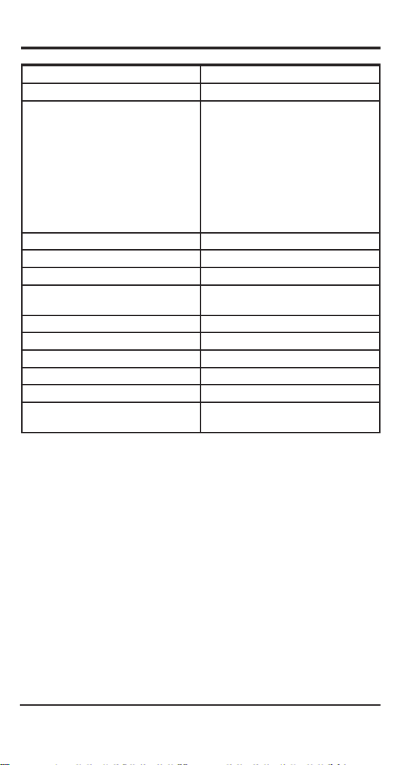
10. N9002 THERMOMETER SPECIFICATIONS
Measurement Thermocouple types K, N, T, J, R, S, E, B
Connector 2-pin sub-min connector
Measurement Range (°C)
Type K
Type N
Type T
Type J
Type R
Type S
Type E
Type B
Scales °C, °F and Kelvin
Resolution 0.1°
Instrument Accuracy at +23°C Better than ± 0.1 % of reading ± 0.2°C
Temperature Coefcient Less than ± 0.01 % of reading
Ambient Operating Temperature Range -25°C to +50°C
Response Time 1 second to full accuracy
Battery Two Type I.E.C. LR6 Size AA
Battery Life (continuous) Greater than 300 hours (Alkaline)
Environmental Protection I.P.67 BS60529 IEC 529
EMC Tested to EN 61326-1
From (°C) To (°C)
-200 +1372
-200 +1300
-200 +400
-200 +1200
-50 +1767
-50 +1767
-200 +1000
+100 +1820
±0.02 °C per °C change from +23°C
Criteria B Performance
Due to our policy of continual product improvement specications are
subject to change without prior notice.
11
Page 13

12
Page 14

Comark Instruments
52 Hurricane Way,
Norwich, Norfolk, NR6 6JB United Kingdom
Tel: +44 844 815 6599
Fax: +44 844 815 6598
Email: sales@comarkinstruments.com
Website: www.comarkinstruments.com
Comark Instruments
PO Box 500, Beaverton
OR 97077 USA
Tel: 503 643 5204
Fax: 503 644 5859
Email: sales@comarkusa.com
Website: www.comarkusa.com
© Comark Instruments Stock No. 18489 Issue 5 (11/12)
 Loading...