

Page 1

Document Reference: MPD-1611291-A
Page 2

USER MANUAL
MPD-1611291-A
EXACT-V2 High End Rack Modulator / Exciter
3/10/2017
Page 2/94
MPD-1611291-A
Page 3

USER MANUAL
MPD-1611291-A
EXACT-V2 High End Rack Modulator / Exciter
3/10/2017
Page 3/94
Table of Content
1 System Overview 9
1.1 General overview .......................................................................... 11
1.2 Block diagram .............................................................................. 12
2 Features Summary 13
2.1 Features Overview ........................................................................ 15
2.2 Input Stream Interfaces ................................................................ 17
2.2.1 ASI/SMPTE Inputs ......................................................................... 17
2.3 Input Stream Management ............................................................ 17
2.3.1 TS CleverSwitch Control ................................................................ 18
2.3.2 Seamless Switching ...................................................................... 19
2.4 Modulation Core ........................................................................... 19
2.5 Test modes operation .................................................................... 19
2.5.1 PRBS sequence ............................................................................. 19
2.5.2 Sinus tone generation ................................................................... 19
2.6 Digital Precorrection ...................................................................... 20
2.6.1 Digital Adaptive Precorrection ......................................................... 22
2.6.2 Manual Digital Pre-correction ............................................................. 25
2.6.3 Adaptive Linear pre-correction for sharp channel filters (in ATSC 1.0) ..... 25
2.7 Output Processing ......................................................................... 26
2.7.1 RF output muting and RF maintain features...................................... 26
2.7.2 Crest Factor Reduction Management ............................................... 27
2.7.3 DAP Operation .............................................................................. 30
2.8 Clock and Synchronization ............................................................. 32
2.8.1 GPS and clock management for VX20-x0x2 ...................................... 32
2.8.2 Warm-up Time ............................................................................. 35
2.8.3 Loss of Reference Sig nal management (L ORS) ................................. 35
2.9 Power Measurements .................................................................... 37
2.10 Automatic Gain Control (AGC) ........................................................ 38
3 EXACT-V2 Rack 39
3.1 EXACT-V2 mechanics .................................................................... 41
3.1.1 Front panel layout ......................................................................... 41
3.1.2 Rear Panel Layout ......................................................................... 42
3.2 Interface characteristics ................................................................ 42
3.3 Front Panel signalization (LEDs description) ..................................... 52
3.4 Power requirements ...................................................................... 53
3.5 Performances and technical characteristics ....................................... 53
3.5.1 General characteristics .................................................................. 53
3.5.2 Control and data Ethernet interfaces ............................................... 53
3.5.3 Serial control interfaces ................................................................. 54
3.5.4 ASI inputs / output and MPEG-TS processing .................................... 55
3.5.5 Digital modulation ......................................................................... 56
3.5.6 Clock synchronization .................................................................... 57
3.5.7 RF and monitoring outputs ............................................................. 59
MPD-1611291-A
Page 4

USER MANUAL
MPD-1611291-A
EXACT-V2 High End Rack Modulator / Exciter
3/10/2017
Page 4/94
3.5.8 Digital precorrection ...................................................................... 60
3.5.9 Power level measurement inputs and AGC ........................................ 61
3.5.10 Dry contacts ............................................................................... 61
3.6 Conformity with EC Directive .......................................................... 62
4 EXACT-V2 Installation 63
4.1 Unpack the Unit ............................................................................ 65
4.2 Installation and Recommendations .................................................. 65
4.2.1 Temperature alarms ...................................................................... 66
4.2.2 Cooling methods ........................................................................... 66
4.3 Wiring and Powering on.................................................................. 66
4.4 Initial Configuration ....................................................................... 67
5 Operation 71
5.1 Operation Generalities ................................................................... 73
5.1.1 Local Operation ............................................................................. 73
5.1.2 Remote Operation ......................................................................... 73
5.2 Embedded Web GUI Description ...................................................... 74
5.2.1 Requirements ............................................................................... 74
5.2.2 Connection to EXACT-V2 ................................................................ 74
5.2.3 General Overview .......................................................................... 75
5.2.4 Settings Tab ................................................................................. 76
5.2.5 Monitoring Tab .............................................................................. 78
5.2.6 Log File ........................................................................................ 79
5.3 Front Panel Menu Description .......................................................... 79
6 Maintenance & Troubleshooting 81
6.1 Versions management.................................................................... 83
6.2 Software updates .......................................................................... 83
6.3 Licence key management ............................................................... 84
6.4 Troubleshooting of the exciter ......................................................... 84
6.4.1 LED Check .................................................................................... 84
6.4.2 Contact the technical support .......................................................... 85
Appendix A GPS Installation Recommendations 87
Appendix B Example of GPS Antenna 91
MPD-1611291-A
Page 5

USER MANUAL
MPD-1611291-A
EXACT-V2 High End Rack Modulator / Exciter
3/10/2017
Page 5/94
Revision sheet
Document Number Revision Date Version Comments
MPD-1611291 A Nov 2016 S100 Document creati on
ATSC 1.0 Version
(ATSC 3.0 Ready)
MPD-1611291 B Feb 2017 S100 Revised
Warning
Content war ning
This document contains preliminary information about some of t he products in the
Hitachi-Comark family. Hitachi-Comark maintains the right to make changes to the
documentation at any time without prior notice in order to improve, design and
supply the best possible product.
Copy warning
This document includes some confidential information. Its usage is limited to the
owners of the product that it is relevant to. It cannot be copied, modified, or
translated into another language without prior wr itten authorization from HitachiComark.
MPD-1611291-A
Page 6

USER MANUAL
MPD-1611291-A
EXACT-V2 High End Rack Modulator / Exciter
3/10/2017
Page 6/94
EXACT-V2-20dB
*Specify at the time of order: UHF, VHF Band 3, or VHF Band I
About this manual
Intended a ud ience
This user manual has be e n written for those who have to use, configure and install
the product. Some chapters require some prerequisite knowledge in electronics and
especially in broadcast technologies and standards.
Product described
The following products are described in this user manual:
EXACT-V2
Commercial references and available options
Product ref. Description
EXACT-V2
EXACT-V2-20dB
EXACT-ATSC 3 VP
EXACT-ALP3
ATSC rack modulator with UHF/VHF* output, DAP and onboard GPS
Optional +20dBm, output, DAP and onboard GPS
ATSC 3.0 software license (Single PLP)
ALP software license (3.0)
Document structure :
• Chapter 1 – System Overview
This chapter gives an overview of the product.
• Chapter 2 – Features Summary
This chapter describes the features found in the product.
• Chapter 3 – EXACT-V2 rack
This chapter describes the mechanics, characteristics and performances
of the product.
• Chapter 4 – Module Installation
This chapter explains how to install the product.
• Chapter 5 – Operations
This chapter explains how to basically operate the product.
• Chapter 6 – Maintenance and Troubleshooting
This chapter gives recommendation on how to maintain the product and
how to perform first level Troubleshooting i n the event of techni cal issues.
MPD-1611291-A
Page 7
USER MANUAL
MPD-1611291-A
EXACT-V2 High End Rack Modulator / Exciter
3/10/2017
Page 7/94
ATSC standards
A/53, A/54
http://www.atsc.org/standards.html
DVB Measurements
ETSI TR 101 290 v1.2.1
www.dvb.org
ATSC Compliance
A/64
http://www.atsc.org/standards.html
SFN Network in ATSC
A/111
http://www.atsc.org/standards.html
Physical Layer Protocol
A/322
http://atsc.org/standards/atsc-3-0-standards/
Link-Layer Protocol
A/330
http://atsc.org/standards/atsc-3-0-standards/
DVB ASI
EN50083-9, ETSI TR101 891 v1.1.1
http://atsc.org/standards/atsc-3-0-standards/
MPEG-2 TS Standard
ISO/IEC 13818-1
http://www.iso.org
IP
RFC-791
www.ietf.org
UDP
RFC-768
www.ietf.org
RTP & MPEG/RTR
RFC-1889 / RFC-2250
www.ietf.org
IP Multicast
RFC-2365
www.ietf.org
Ethernet
IEEE-802.3
http://www.ieee802.org/3/
Multicast protocol IGMP
RFC-2236 / RFC-3376
www.ietf.org
Associated publications
The reader of this document could improve their understanding of the product and
its effective use by reading the following documents:
[A1]
[A2]
[A3]
[A4]
Table 1: Relev ant st a nd a rds for ATSC
[A6]
[A7]
Table 2: Relevant standards for ATSC 3.0
[D1]
[D2]
Table 3: Other standards
[I1]
[I2]
[I3]
[I4]
[I5]
[I6]
Table 4: Relev ant st a nd a rds for IP
MPD-1611291-A
Page 8

USER MANUAL
MPD-1611291-A
EXACT-V2 High End Rack Modulator / Exciter
3/10/2017
Page 8/94
MPD-1611291-A
Page 9

USER MANUAL
MPD-1611291-A
EXACT-V2 High End Rack Modulator / Exciter
3/10/2017
Page 9/94
1 System Overview
MPD-1611291-A
Page 10

USER MANUAL
MPD-1611291-A
EXACT-V2 High End Rack Modulator / Exciter
3/10/2017
Page 10/94
MPD-1611291-A
Page 11

USER MANUAL
MPD-1611291-A
EXACT-V2 High End Rack Modulator / Exciter
3/10/2017
Page 11/94
1.1 General overview
EXACT-V2 exciter has been especially designed to support, in addition to ATSC 1.0, the
complex ATSC 3.0 modulation scheme, including Digital Adaptive Pre-correction (DAP)
circuits and all required mechanisms to feed transmitters with flexible and highly
secured input stream formats. This ready-to-use high-end 1RU exciter offers the bestin-class performance for broadcasters that want to launch ATSC 1.0 or ATSC 3.0
products with a high-performing, secured solution. Enabling users to migrate ATSC 3.0,
reusing and recycling their existing transmission system, this unique exciter
significantly reduces capital expenditure (CAPEX) costs.
In order to bring the highest performance, EXACT-V2 integrates up-to-date FPGA
technology and sophisticated digital signal processing algorithms, especially for the
modulation and the output filtering processes. With this in mind, broadcasters are able
to take full advantage of ATSC 3.0 technology.
The clock system has been carefully designed to reach a very low phase noise and it
achieves the flexibility required to operate with different synchronization schemes.
EXACT-V2 inclu des a high -stability OCXO oscillator and an on-board GPS receiver. It
generates a fully modulated analogue signal and includes all necessary clock &
synchronization features for high quality ATSC 3.0 synchronization, especially for SFN
networks.
Fully controlled via a user friendly WEB GUI and via SNMP (optional), EXACT-V2 also
features some very unique functionalities such as a Power Measurement Unit
(measuring in real-time the forward and reflected power levels), the TX power ON/OFF
control and the Automatic Gain Control (AGC ) mechanism. EXACT-V2 Digit a l Ad aptive
Pre-correction (Digital Adaptive Processing) algorithm, permits transmitter operation
very close to the saturation limit with unequalled RF signal performance and allows for
significant gain in transmitter Power Efficiency. This generates significant savings in
operating expen ses (O PEX).
Three Ethernet control ports are available, which provides the o pportunity to upgrade
a legacy transmitter configuration into a fully IP-controlled solution!
MPD-1611291-A
Page 12

USER MANUAL
MPD-1611291-A
EXACT-V2 High End Rack Modulator / Exciter
3/10/2017
Page 12/94
1.2 Block diagram
The generic block diagram is described below:
Figure 1: EXACT-V2 functional block diagram
EXACT-V2 features two ASI/SMPTE input streams that can be processed in parallel for
stream redundancy (Primary/Secondary). Four IP streaming (Gigabit) input/output
ports are reserved for ATSC 3.0 mode.
The clock and synchronization process has bee n carefully designed to reach the best
performance for all of the supported standards. 1 PPS and 10MHz external reference
signals are available to reach a higher frequency accurac y. An on-board GPS receiver
is also available and may be used for this purpose.
Regarding the control and management of EXACT-V2, an embedded web server
provides a user-friendly graphical user int erface (GUI) that that can be acce ssed by
any web browser. Three IP control ports are available.
Two connectors are provided for the feedback inputs from the amplifier (FBA_IN ) and
from the filter (FBF_IN). Thes e inputs are used for the Digita l Adaptive Precorrection
(DAP).
A serial port is also available for complete transmitter control and monitoring
integration within the modulator’s Web GUI.
MPD-1611291-A
Page 13

USER MANUAL
MPD-1611291-A
EXACT-V2 High End Rack Modulator / Exciter
3/10/2017
Page 13/94
2 Features Summary
MPD-1611291-A
Page 14

USER MANUAL
MPD-1611291-A
EXACT-V2 High End Rack Modulator / Exciter
3/10/2017
Page 14/94
MPD-1611291-A
Page 15

USER MANUAL
MPD-1611291-A
EXACT-V2 High End Rack Modulator / Exciter
3/10/2017
Page 15/94
2.1 Features Overview
Input Stream Management
ATSC 1.0 :
o 2x ASI/SMPTE 310M Inputs :
ASI: 188 or 204 byte format with RS decoding – TS/ASI (ETSI EN
102 773 - [D1] & [D2])
SMPTE 310M: 188 byte format
o 1x ASI Output (188 byte) – Stream output type: TS/ASI
o Redundancy management :
TS CleverSwitch: stream switching between Main and Secondary input
– See TS CleverSwitch control
o Bit rate adaptation & PCR re-stamping
o Null packet deletion
ATSC framing and channel encoding
o 8-VSB modulation core
o Virtual Channel Table Update
ATSC 3.0 : (Available from the S110 firmware version)
Digital Adaptive Non-Linear Precorrection circuits
o Flexible operating modes: STATIC (EDIT), SINGLE, SURVEY or
CONTINUOUS
o RF feedback signals sampled in real-time after Power Amplifier
Digital Linear Precorrection circuits
o Manual mode
o Adaptive mode : STATIC (EDIT) or SINGLE
o RF feedback signals sampled in real-time after RF filter
PAPR reduction system and protection clipping
RF output
o Frequency band: UHF and VHF band
o Bandwidth: 6MHz
o Main output (0dBm or optional +20dBm) and monitoring output (-20dB
relative to main output)
MPD-1611291-A
Page 16

USER MANUAL
MPD-1611291-A
EXACT-V2 High End Rack Modulator / Exciter
3/10/2017
Page 16/94
Note: Availability of features
notes).
o Manual mute and programmable mute condition on LORS
o RF maintain function on stream input loss
Clock and synchronization signal management
o External reference sources: 1PPS, 10MHz inputs
o Onboard GPS (VX20-x0x2)
o 10 MHz reference output
o LORS management
Measurement/Monitoring
o ATSC1.0: MER and shoulder level monitoring (indicative)
o 2 dedicated inputs for forward and reflected powers measurement
AGC feature
o Capacity to automatically adjust the output power to ensure a stable
system output power
o Feedback input using direct adapted RF signal from amplifier output (-
10dBm) or VDC signal from external power sensor
Control and Management
o Control and monitoring via web based GUI
o LCD front panel for main features control and monitoring
o 4 front panel status LED’s
o Alarm relays
o 1+1 Redundacy proprietary management
o 2 Ethernet control ports on rear panel
o 1 Ethernet control ports on front panel
Transmitter Environment Interface
o Full control/monitoring using seamless
Web GUI
o Based on Hitachi-Comark serial protocol
and integrated serial port
Other
o 110-240 VAC
depends on software
release version.
(Please refer to the
product release
o 1RU rack form factor
MPD-1611291-A
Page 17

USER MANUAL
MPD-1611291-A
EXACT-V2 High End Rack Modulator / Exciter
3/10/2017
Page 17/94
2.2 Input Stream Interfaces
2.2.1 ASI/SMPTE Inputs
The unit offers 2 ASI/SMPTE inputs compliant either with DVB-ASI ([D1] & [D2]) or
with SMPTE 310M. They can be used either in single or redundant mode. 188 or 204
byte packets without RS coding and 204 byte packets with RS coding are supported
when used in ASI mode. If 204 byte packets including RS coding are prov ided, then
the RS error checking and correction are performed. Both ASI “Packet mode” and “Burst
mode” are supported. When used in SMPTE 310M mode, only 188-byte format is
supported.
Input Equalizer
Each input has an equalizer that can be turned ON or OFF. This equalizer works well to
equalize cable length attenuation but does not perform as well if the input cable is
mismatched. If this is the case, and in the case of SMPTE 310M input mode being used,
the Equalizer should be turned off.
2.3 Input Stream Management
The Stream Management consists in routing the incoming data from the ASI/SMPTE or
the Ethernet interface towards the modulation core. This part can manage all types of
interfaces and it also provides the TS output stre am for the ASI output interface . The
Stream Management process might operate additional basic functions such as data
monitoring, data extraction, bit-rate adaptation and routing.
Bit-rate adaptation: When using an external clock reference, the global clock
synchronization might be plesiochronous (i.e. small clock deviance between the
multiplexer and the modulator reference). In that case, it is recommended to enable
the bit rate adaptation. When this mode is activated, the unit discards or inserts null
packets in order to accurately adapt the TS input bit-rate to the bit-rate defined by the
selected ATSC mode. PCR re-stamping is then executed accordingly.
At last, an ASI output has been designed f or copying either one of the input streams
(ASI1, ASI2 or the TS from the active IP input) on the Active_Stream.
MPD-1611291-A
Page 18
USER MANUAL
MPD-1611291-A
EXACT-V2 High End Rack Modulator / Exciter
3/10/2017
Page 18/94
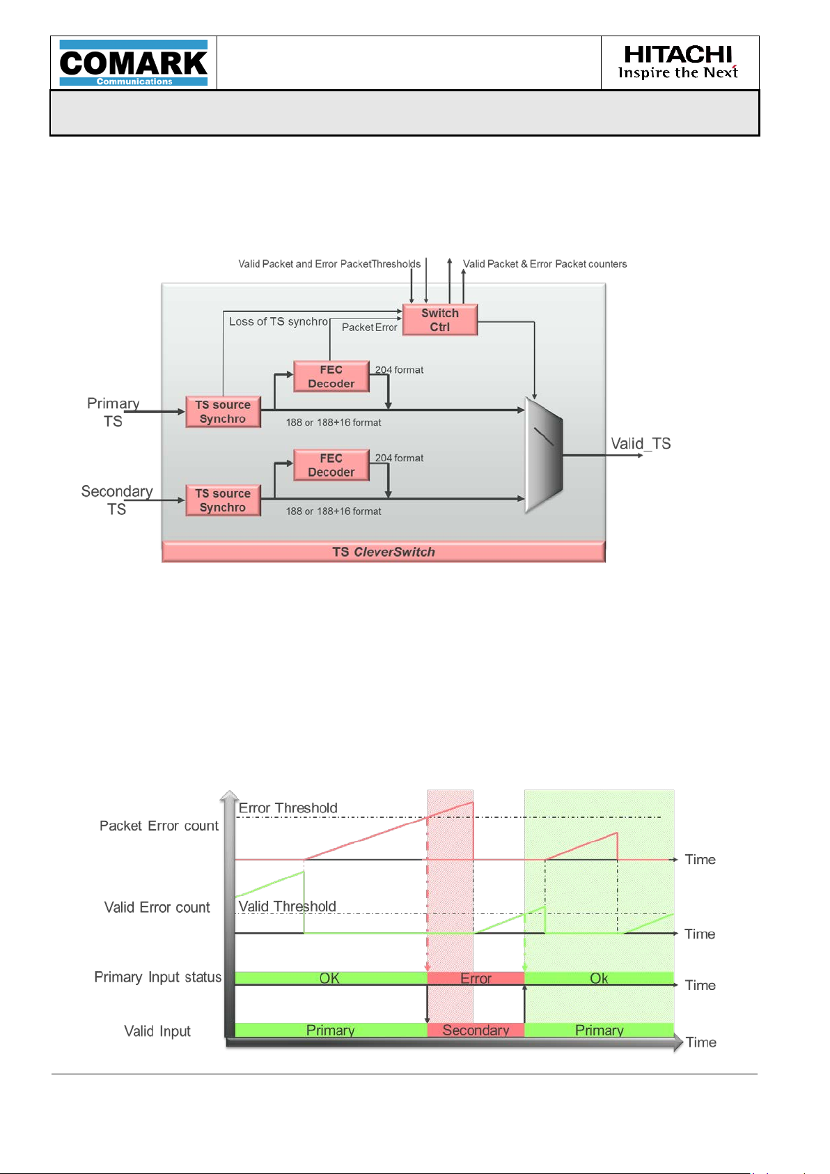
2.3.1 TS CleverSwitch Control
CleverSwitch is a flexible input redundancy management mechanism designed by
Hitachi-Comark. It is enabled by default and can be manually disabled or enabled.
Figure 2: TS CleverSwitch block diagram
CleverSwitch is based on a programmable consecutive error threshold. Once it is
reached, the stream selection switches automatically from the primary input to the
secondary. When the valid packets threshold is reached, the stream input switches
back to the primary. In 188 byte format, the switch criteria only considers the number
of consecutive valid and error packets (0x47 sync detection), whereas in 204 byte
mode, it also uses the RS errors. The switch decision is implemented only on the
primary input. The switch-back is manual or automatic in case of secondary signal
failure.
MPD-1611291-A
Page 19

USER MANUAL
MPD-1611291-A
EXACT-V2 High End Rack Modulator / Exciter
3/10/2017
Page 19/94
Note: Use of either sinus tone might damage the power amplifier.
2.3.2 Seamless Switching
The switching (and switching back) performed by the TS CleverSwitch between the
primary and the secondary stream is not expected to be seamless. However, if the
exact same data stream is present on both inputs (Primary & Secondary) then the
modulator performs seamless switching between inputs. Switching is made on a packet
basis.
2.4 Modulation Core
The modulator is fed by the active TS stream coming out of the CleverSwitch. It then
delivers IQ samples towards the Digital Pre-corrector.
From S110 version, it will support both ATSC 1.0 and ATSC 3.0 standards in the same
firmware. The user just selects the desired standard using a simple command.
In ATSC 1.0:
VCT (Virtual Channel Table) updates allows the user to change the major channel
number and carrier frequency.
In ATSC 3.0:
(Available from the S110 firmware version)
2.5 Test modes operation
2.5.1 PRBS sequence
A PRBS sequence can be internally generated and inserted at the input of the modulator
instead of an external MPEG-TS or I P Packets. The PRBS polynomial coefficients are
configurable.
2.5.2 Sinus tone generation
Two sinus tone modes are availab le: sinus and +6dB Bo osted sinus. In these modes,
the output RF signal is replaced by a simple sinus wave at the RF frequency. The
boosted mode allows phase noise measurement without the requirement of an external
amplifier. Sinus tone generation should only be used if the exciter is being bench tested
(ie. not connected to the transmitter).
MPD-1611291-A
Page 20
USER MANUAL
MPD-1611291-A
EXACT-V2 High End Rack Modulator / Exciter
3/10/2017
Page 20/94
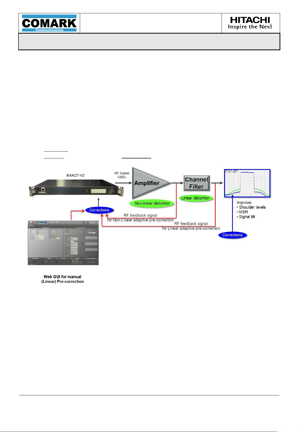
2.6 Digital Precorrection
The digital pre-correction feature is available for both ATSC 1.0 and ATSC 3.0 signal
waveforms.
The digital precorrection feature consists of two types of correction:
o Linear precorrection for compensating the distortion due to the channel
filter
o Non-linear precorrection in order to cope with the power amplifier
distortion
Digital precorrection can be:
adaptive: running automatically thanks to an internal (DAP) algorithm
manual: curves are set via TuneCast software (usi n g IP connection)
The EXACT-V2 product integrates both Linear and Non-Linear Digital Adaptive
Precorrection, as well as Linear manual precorrection.
Figure 3: Linear & Non-Linear Precorrection methods
MPD-1611291-A
Page 21

USER MANUAL
MPD-1611291-A
EXACT-V2 High End Rack Modulator / Exciter
3/10/2017
Page 21/94
The use of adaptive precorrection is generally preferred not only in order to reach
higher performance and efficiency, but also in order to save on technician time.
However, when several RF signals are combined together (adjacent channels), the use
of Linear DAP i s not possible because the feedback signal is then a combined spectrum
of several channels. In that case a manual Linear precorrection is needed.
Figure 4: Linear DAP typical use-case
Figure 5: Manual Linear Precorrection use-case – Combined filter
MPD-1611291-A
Page 22

USER MANUAL
MPD-1611291-A
EXACT-V2 High End Rack Modulator / Exciter
3/10/2017
Page 22/94
2.6.1 Digital Adaptive Precorrection
The Digital Adaptive Precorrection (DAP) block is illustrated here below.
Figure 6: DAP integration block diagram
The DAP function is composed of Non-Linear and Linear Precorrection and a dedicated
down-converter. The down-converter receives the s ignal feedback after the external
amplifier (FBA_In) and after the RF filter (FBF_In). Then, a particular algorithm
processes the digital IQ samples to reduce the signal distortions at the transmitter
output.
To monitor the DAP process several statuses are available:
MER indicative measure
PAPR indicative measure
Measured left and right shoulder levels
DAP elapsed time
DAP status: Active, Stopped by user, Stopped by timer, Failed
2.6.1.1 Non-Linear Adaptive Precorrection
EXACT-V2 performs non-linear precorrection over a 75 MHz bandwidth. The purpose of
non-linear precorrection is to correct the distortion from the power amplifier. With the
feedback from the output amplifier, an adaptive non-linear precorrection should
automatically find the best precorrection and follow the variations of the amplifier
characteristics.
Four operating modes are available:
• STATIC (EDIT) mode: The DAP is disabled. The user can load a previous DAP
configuration to be applied to the modulator.
MPD-1611291-A
Page 23

USER MANUAL
MPD-1611291-A
EXACT-V2 High End Rack Modulator / Exciter
3/10/2017
Page 23/94
• SINGLE DAP: The DAP process is manually started and is stopped either by a
timer value (user configurable) or manually stopped.
Figure 7: Single DAP mode operation
• SURVEY DAP: In this mode, the DAP process is started as the Single DAP mode.
Once the timer is reached, then the DAP process can be automatically restarted
if a shoulder or MER deviation is detected (user configurable).
Figure 8: Survey DAP mode operation
MPD-1611291-A
Page 24

USER MANUAL
MPD-1611291-A
EXACT-V2 High End Rack Modulator / Exciter
3/10/2017
Page 24/94
• CONTINUOUS DAP: The DAP works continuously until the user exits continuous
mode.
Figure 9: Continuous DAP mode op er ati o n
2.6.1.2 Linear Adaptive Precorrection
The purpose of Linear precorrection is to correct the distortion in amplitude and in
group delay of the output filter. The precorrector is based on a complex FIR filter which
can correct up to 3dB (range -3dB to 3dB) in amplitude and up to 3µs (range 0 to 3µs)
in group delay.
With the feedback after the output filter, an adaptive linear precorrection should
automatically find the correct precorrection curve in a few minutes.
Two operating modes are possible:
• STATIC (MANUAL EDIT) mode: The DAP is disabled. The user can load a
previous DAP configuration to be applied to the modulator or can edit the
precorrection curves manually.
• SINGLE mode: The user starts the adaptive precorrection manually. The
adaptive precorrection process is stopped i f the timeout val ue has been rea ched
or if the user stops the process manually.
MPD-1611291-A
Page 25

USER MANUAL
MPD-1611291-A
EXACT-V2 High End Rack Modulator / Exciter
3/10/2017
Page 25/94
Note: Using the Set Linear Curves command, the processing time required by the
module (for computing the corresponding coefficients) can be long. It is
coefficients.
2.6.2 Manual Digital Pre-correction
In addition to digital adaptive precorrection, EXACT-V2 also performs manual linear
precorrection. Using the “MANUAL EDIT” mode, both amplitude and phase corre ctions
are performed over the full spectrum of the signal.
For this purpose, a table of 32 points can be loaded in the modulator with the Set Linear
Curves command. The table defines the amplitude and the phase precorrection that
will be applied on the spectrum. For each point, a correction of ±3 dB can be de fined
for the amplitude and ±500 ns for the phase. The 32 points are equally spaced over
the useful spectrum. The module itself then computes the c orrection to each carrier
accordingly.
6 MHz
Useful bandwidth 5.71 MHz
Frequency spacing between
184 KHz
2 consecutive points
Table 2: Linear precorrection - frequency s paci ng
therefore recommended to use the busy flag ( a va i la b le in Get Linear Status
command) before any further module request, or even better: the command
Set Linear Coefficients can be used instead in order
to directly load the
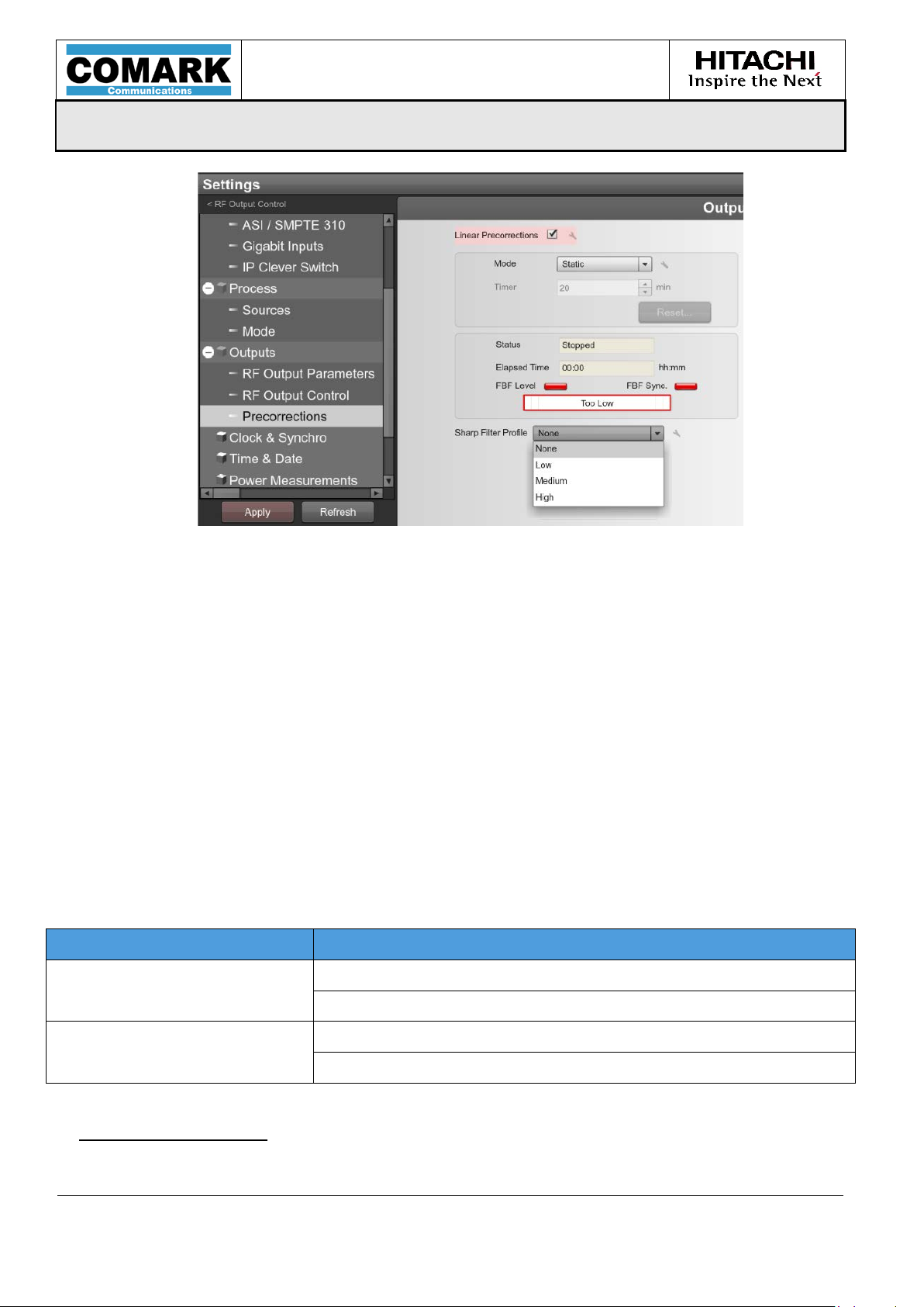
2.6.3 Adaptive Linear pre-correction for sharp channel filters (in ATSC 1 . 0)
With specific, sharp tuned filters, the EXACT-V2 Linear DAP algorithm could fail.
Generally, the complexity of the channe l filter is due to the fact that this filter is so
tight. The compensation of such filtering requires a h igh leve l digital filter algorithm.
The channel filter is so tight that DAP synchro nization mechan is ms cannot stay locked
after a few iterations.
Hitachi-Comark has developed a dedicated method to improve the Linear precorrection
for sharp filters. An additional digital filter process located after the original Linear DAP,
known as the “Sharp Filter Profile” can be activated. This filter can be configured in the
Web GUI in the “Settings/Precorrections” screen:
MPD-1611291-A
Page 26
USER MANUAL
MPD-1611291-A
EXACT-V2 High End Rack Modulator / Exciter
3/10/2017
Page 26/94
Figure 10: Sharp Filter Profile menu
2.7 Output Processing
The nominal output level of the main output “RF Out” is 0 dBm for the standard exciter
and 20dBm for the exciter with optional preamp. An attenuation between 0 and 17 dB
per increment of 0.1 dB can be set. In addition, an offs et gain between -1 dB and + 1
dB per i ncrement of 0.1 dB can be set. If needed, the output spectrum can be reversed.
A copy of the main signal is available on the “RF Monitor”. Th is output signal is the
same as the main "RF Out" signal but with a lower level (-20dB for the 0dBm e xciter,
and -43dB for exciter with optional +20dBm internal preamp).
2.7.1 RF output muting and RF mainta in feature s
The output can be muted either by the user or automatically in some conditions. The
un-mute is pre-configured to “progressive” (2 seconds). The mute function is available
for both ATSC standards.
Mute Mode Mute cases & conditions in ATSC
Manually set
Starting Delay (after a boot)
Manual Mute
Configurable mute conditions
RF Maintain feature:
Warm-up Time (before 10MHz regulation starts)
Loss of Reference Tim eOut (LORS) see LORS Management
Table 3: Mute ca ses a nd conf i gurable mute conditions
MPD-1611291-A
Page 27
USER MANUAL
MPD-1611291-A
EXACT-V2 High End Rack Modulator / Exciter
3/10/2017
Page 27/94
The “RF Maintain” feature consists in keeping an RF signal presence out of the
modulator in o rder to allow a constant power at the modulator R F output during an
input stream error (the function “RF Maintain on Input Stream Error” shall then be
enabled).
The overall objective is to avoid any RF signal interruption at the output of the
modulator for protecting the amplifier.
When the “RF maintain” feature is selected, specific data is not broadcasted during the
switching time from one input stream to another. A PRBS-like signal is used to maintain
the original RF signal and RF power level. Thus the broadcasted signal cannot be
decoded by any receiver.
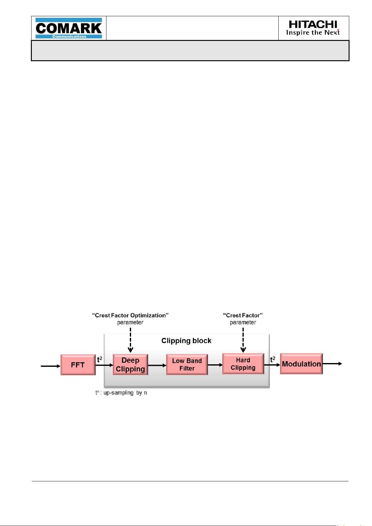
2.7.2 Crest Factor Reduction Management
PAPR (Peak to Average Power Ratio) issues are associated with high power peaks
present in the signal. By correctly managing PAPR reduction (Crest Facto r reduction),
the user will be able to avoid high power peaks from the modulator and so increase the
output power level from the amplifier. It will then allow the best coverage for a given
transmission site. However, this PAPR reduction feature will decrease MER performance
as well as shoulder levels. It must be used carefully after studying the following
explanations.
The PAPR solution uses two clipping modules for the best efficiency. Figure shows the
location of the two modules as well as the user parameters.
Figure 11: PAPR block diagram
2.7.2.1 Crest Factor Parameter
In order to reduce these peaks and avoid damage to the amplifier, the exciter uses a
“crest factor” parameter. It is used to set th e cl ipping le vel of th e s ign a l . T he range is
MPD-1611291-A
Page 28

USER MANUAL
MPD-1611291-A
EXACT-V2 High End Rack Modulator / Exciter
3/10/2017
Page 28/94
Crest Factor
Note: In the screenshots above, the measurements are made using the <RF> value
value, which is also commonly used and i s about 3db less.
from 8dB to 20dB. The default value is 10 dB, meaning that a light crest factor reduction
is performed.
The following figures display the Crest Factor parameter impact on a signal:
Crest Factor
setting = 20dB
(No reduction)
setting = 11dB
Without any crest factor
reduction, the PAPR is 14.4dB
After the adjustment, PAPR is
10.8dB
because the crest factor limit is fixed in the modulator using the RF value.
Please note that some equipment may consider the <ENV> (Envelope)
MPD-1611291-A
Page 29
USER MANUAL
MPD-1611291-A
EXACT-V2 High End Rack Modulator / Exciter
3/10/2017
Page 29/94
2.7.2.2 Crest Factor Optimization Parameter
In order to allow the best amplifier eff iciency a “Cre st Facto r Optimizat ion” parameter
has also been added. It is active when the crest facto r reduction is enabled (value ≠
0).
For a given “Crest Factor”, the “Crest Factor Optimization” enhances the signal
shoulders. Finding the best value for th is parameter allows the u ser to gain dB on the
shoulders of the signal, thus optimizing the amplifier power.
This shoulder optimization involves a limited reduction in MER performance. That is
why the user must find the best trade-off for the best efficiency.
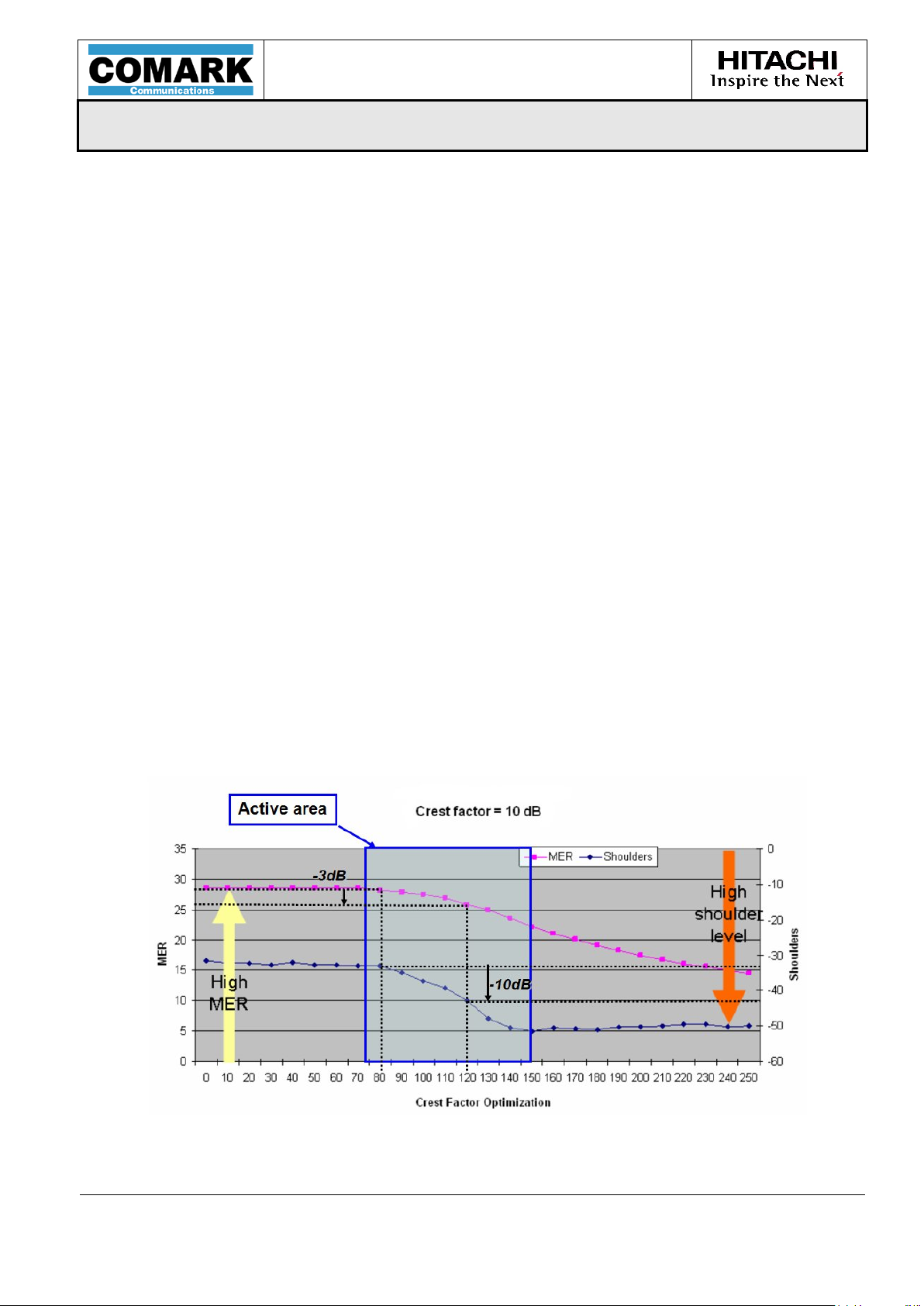
This parameter can vary in a range from 0 to 255 (no unit). Figure shows the variation
of the shoulder level and the MER for different parameter values at a given crest factor.
When the Crest Factor Optimization parameter is increased, the shoulder level becomes
better (from -33dBm to -50dBm). At the same time, the MER pe rformance decreases
(from 28dB to 15dB). As explained earlier, a trade-off between the two is necessar y to
obtain the best overall optimization.
In addition, due to curve shape we see there is an ideal range for the Crest Factor
Optimization parameter of about 70 to 150. In this range the variation of both shoulder
level and MER are significant. Out of this range the loss of MER is too severe for little
or no shoulder level gain. For instance, for a Crest Factor Optimization of 120, we
observe a gain of 10 dB f or t h e s h ou lder level and a loss of on ly 3dB for the MER.
Hitachi-Comark therefore recommend s that this parameter be set in the ideal range of
70 to 150.
Figure 12: Crest Factor Optimiz at io n Im p act
MPD-1611291-A
Page 30
USER MANUAL
MPD-1611291-A
EXACT-V2 High End Rack Modulator / Exciter
3/10/2017
Page 30/94
Note: Protection Clipping = 20 means OFF
Recommended value to start = 15dB (default value)
2.7.2.3 Protection Clipping Parameter
Since adaptive precorrection can produce power peaks at the modulator output, a
“protection clipping” has been added at the output of the modulator. It will allow the
user to protect the amplifier input by clipping the signal out from the modulator.
2.7.3 DAP Operation
stands for “Digital Adaptive Precorrection”, it is an option allowing the user to run
DAP
the EXACT-V2 in a very high-end mode in order to reach unequalled RF signal
performance and to allow a significant gain in transmitter Power Efficiency.
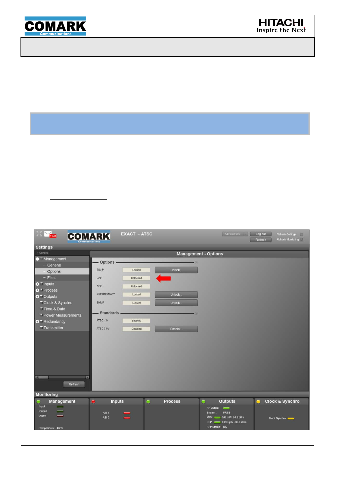
License activation
First, the use of the DAP mode requires the user to unlock the “DAP” license key. This
can be done in the Settings Tab under Management > Options
MPD-1611291-A
Page 31
USER MANUAL
MPD-1611291-A
EXACT-V2 High End Rack Modulator / Exciter
3/10/2017
Page 31/94
Note: Enabling or disabling the DAP causes a reset of the non-linear curves.
The user is then given the possibility to save the current curves, if needed.
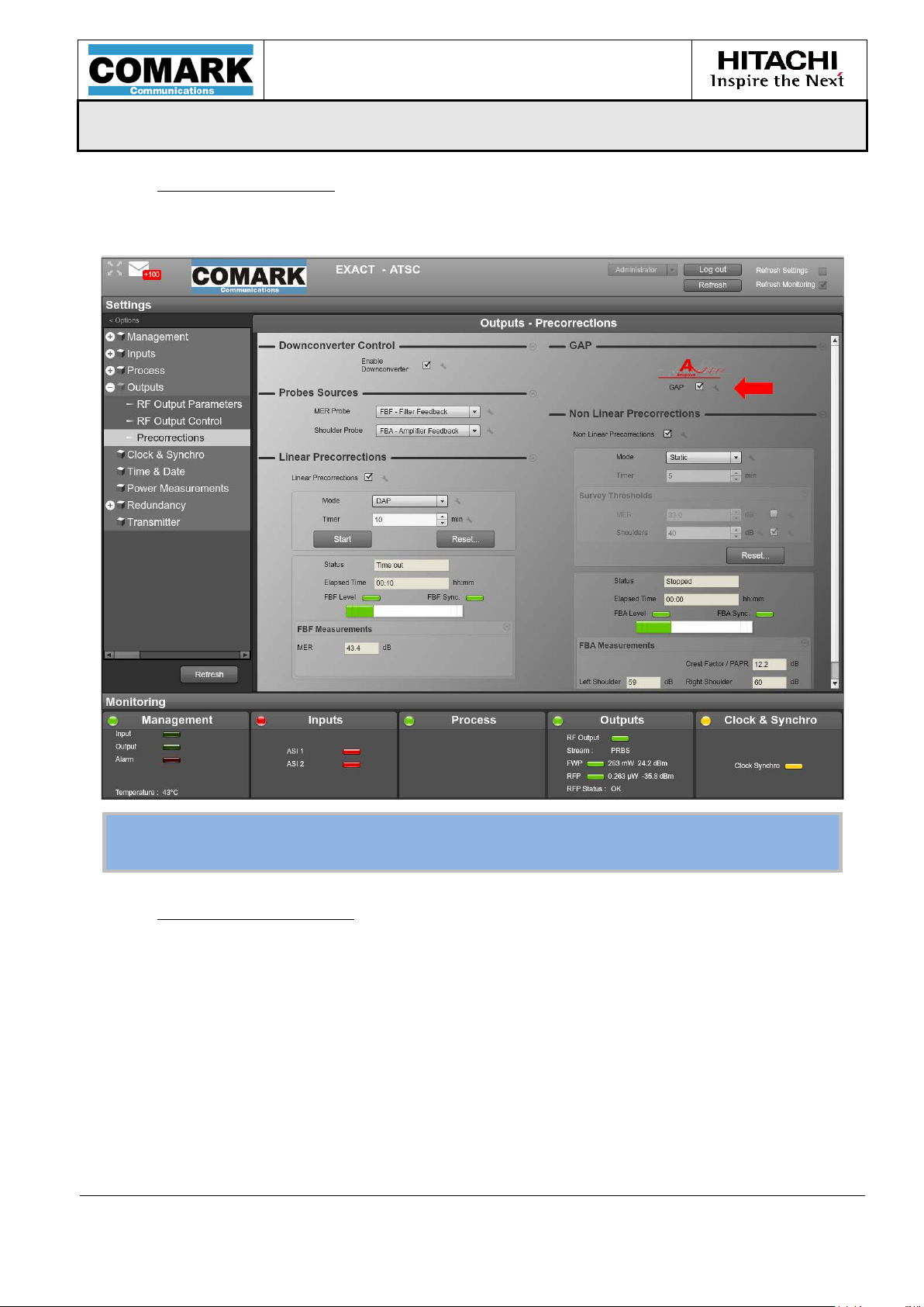
DAP mode activation
In the Settings Tab, the DAP mode can be enabled under Outputs > Precorrections:
Non-Linear DAP launch
The same protocol as the basic DAP applies (please refer to the previous chapter).
MPD-1611291-A
Page 32

USER MANUAL
MPD-1611291-A
EXACT-V2 High End Rack Modulator / Exciter
3/10/2017
Page 32/94
Note: The GPS configuration parameters (location & time) is kept in the memory
for faster synchronization after reset or ON/OFF.
2.8 Clock and Synchronization
The clock and synchronization function is responsible for synthesizing the required
temporal signals and data rates . A high-stability 10 MHz OCXO provides the internal
clock reference.
However, if synchronization with other equipment is required, an external 10 MHz clock
signal can be chosen as a reference together with external 1PPS. The user shall
configure the signal reference edge (rising or falling edge) . An inte rnal 1 PPS signal is
generated from the external signal in order to maintain synchronized the output signal
as long as possible in case of external signal failure.
The modulator clock ref er en ce (10MHz) source can be configured as:
o Locked on the external 10 MHz signal reference (by default),
o Derived from the 1PPS source (either on-board GPS or external 1PPS)
o Internal.
The module delivers a 10 MHz clock reference output signal and can also provide 1PPS
if the user configures the “1PPS IN/OUT” connector as an output. For VX20-x0x2 (with
on-board GPS), the 1PPS output is derived from the on-board GPS.
2.8.1 GPS and clock management for VX20-x0x2
For VX20-x0x2, the on-board GPS block gives the possibility to directly receive an
incoming GPS or Glonass signal. Please refer to Appendix C for GPS installation
recommendations and Appendix D for GPS antenna recommendations.
Up to four satellite signal levels may be displayed (Note: In case of GPS/Glonass, the
four strongest levels are chosen amongst the eight total signals available.) Signal
level is normally positive. If it is zero, this means that no satellite lock has been
acquired yet. If it is negative, then that satellite is not being locked. The absolute
value of a signal level field is the last known signal level of that satellite.
MPD-1611291-A
Page 33

USER MANUAL
MPD-1611291-A
EXACT-V2 High End Rack Modulator / Exciter
3/10/2017
Page 33/94
The figure below shows the entire VX20-x0x2 synchronization processing block (the
on-board GPS being depicted as “GPS receiver”):
Figure 13: VX20-x0x2 synchronization processing block
Then, depending on the user’s setup, three cases can be considered:
1) Working with external GPS signal reference (using on-board GPS receiver):
Figure 14: VX20-x0x2 clock synchronization - GPS signal
In this case, the modulator processes the 1PPS due to the on-board GPS receiver. The
GPS reference signal is available on GPS In interface. This 1PPS reference signal is used
both for temporal synchronization and 10 MHz PLL locking. The 1 PPS I/O can be
configured as an output to provide a 1PPS signal to other equipment.
MPD-1611291-A
Page 34
USER MANUAL
MPD-1611291-A
EXACT-V2 High End Rack Modulator / Exciter
3/10/2017
Page 34/94
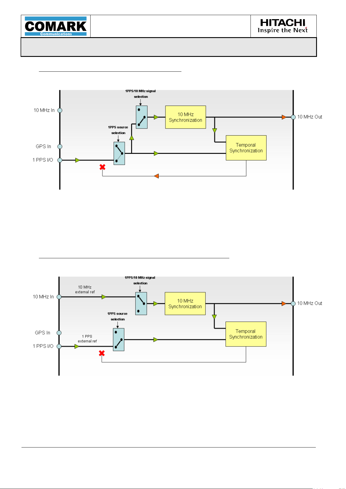
2) Working with external 1PPS reference signal:
Figure 15: VX20-x0x2 clock synchronization – external 1PPS signal
In this case, the modulator d irectly uses the 1PPS available from the external source
available on the 1PPS I/O interface. This 1PPS reference signal is used for both temporal
synchronization and 10 MHz PLL locking.
3) Working with external 10 MHz and external 1PPS reference:
Figure 16: VX20-x0x2 clock synchronization – external 10 MHz and 1PPS signal
In this case, the modulator use s the external 10 MHz signal as well as the external
1PPS signal available on the 10 MHz In and 1PPS I/O interfaces, res pe ctively.
A 10 MHz reference signal is always available on the 10 MHz Out interface.
MPD-1611291-A
Page 35

USER MANUAL
MPD-1611291-A
EXACT-V2 High End Rack Modulator / Exciter
3/10/2017
Page 35/94
Note:
considered ad reserved for Future Use (RFU).
2.8.2 Warm-up Time
This part aims at describing the WARM-UP function which has been designed for
compensating the start-up delay of the OCXO (for instance, in case of AC power loss).
In order to be stable the internal temperature of the OCXO must be stabilized and equal
to 85°C. However, this could take up to 5 minutes to obtain a stable 10MHz reference.
During this unstable situation, the OCXO response is not linear and the 10MHz
regulation algorithm takes a long time to converge. The WARM-UP survey has been
defined for optimizing the 10MHz behaviour during that time.
If it is en ab led , the W ARM-UP function is a new s tate of the 10MHz regulation, during
which it is deactivated until the external reference is stable again. The 10 MHz
regulation then starts again after that state is finished.
This WARM-UP time typically takes 3-4 minutes and is limited to 10 minutes in any
case.
2.8.3 Loss of Reference Signal management (LORS)
LORS is not useful when operating in MFN-Standalone configuration and shal l be
In SFN, an accurate clock synchronization is very critical for ensuring a good SFN
operation. For this purpose, the module implements the following operating modes in
case of loss of the synchronization signal reference(s) (LORS). When losing temporal
synchronization, it can be set to automatically mute a fter a variable delay (Time Out
counter) also set by the user, from 0 (immediate mute) to 1440 min (24 hours), by 1
minute steps.
In the table below, it is assumed that the primary clock is 10MHz and the secondary
clock is 1 PPS:
10 MHz 1 PPS Operating Mode Status
Detected Detected Normal No alarm
Detected Loss of Signal Clock_source= External
10MHz
Loss of Signal Detected Clock_source= External 1PPS External 10 MHz
Loss of Signal Loss of Signal Clock_source= Internal
(Configurable Mute after LORS
TimeOut)
Unlocked PLL - Configurable Mute on SFN Not
Ready
External 1 PPS
warning
warning
External 1 PPS &
10 MHz critical alarms.
PLL_ Unlocked status
= SFN not ready
Table 4: LORS management table
MPD-1611291-A
Page 36

USER MANUAL
MPD-1611291-A
EXACT-V2 High End Rack Modulator / Exciter
3/10/2017
Page 36/94
The PLL_Unlocked status (Mute on SFN Not Ready) is used in order to maintain that
the output signal is muted (please refer to the mute conditions in chapter RF output
muting and RF maintain features.)
In case of SFN application, an optional functionality “PPS auto resync” is available to
allow resynchronization of the inte rnal PPS (used as a reference time in SFN) when
10MHz clock control is locked. This optional functionality allows having the best
accuracy on time reference PP S u sed f or SFN systems.
The external references have to follow the recommendations specified in the interface
description § Interfaces characteristics. The switching is seamless from external
reference signal to the 10 MHz internal clock.
Note: In case both Mute conditions “Mute on LORS” and “Mute on Clock Not Synchro”
(or “Mute on SFN Not Ready”) are enabled, the M ute will occur only after the LORS
TimeOut has ended, as shown in the chronograms below:
1. Mute behaviour when:
Mute on LORS is enabled
Mute on Clock Not Synchro is enabled
LORS TimeOut is reached
Figure 17: Mute behaviour – LORS TimeOut is reached
MPD-1611291-A
Page 37

USER MANUAL
MPD-1611291-A
EXACT-V2 High End Rack Modulator / Exciter
3/10/2017
Page 37/94
2. Mute behavior when:
Mute on LORS is enabled
Mute on Clock Not Synchro is enabled
LORS TimeOut is not reached
If the LORS TimeOut is not reached when the clock reference comes back, another
timeout starts (fixed to 60 sec), after which the module will mute if the Clock Synchro
is still not OK:
Figure 18: Mute behavior – LORS TimeOut is not reached
2.9 Power Measurements
EXACT-V2 provides the capability to measure the forwarded and reflected RF power
output from the transmitter, as described in the following figure.
Using an RF coupler, the user will connect the output of the transmitter to both FWP_In
and RFP_In dedicated inputs.
Each input is able t o receive:
- An RF signal from 0 to -20dBm (±0.5dBm accurac y from 0 to -10dBm, ± 1dBm
accuracy from 0 to -10dBm)
Figure 19: Power measurement
MPD-1611291-A
Page 38

USER MANUAL
MPD-1611291-A
EXACT-V2 High End Rack Modulator / Exciter
3/10/2017
Page 38/94
- A VDC signal from an external power sensor from 0 to 5VDC
The working mode is configurable using the WEB GUI.
Depending on the mode selected, additional parameters will be needed, such as the
coupler sample value or external sensor offset/slope factor, to ensure an accurate
measurement. Please refer to you external device user manual.
Minimum and maximum warning and alarm thresholds for both forward and ref lected
power can be set via WEB GUI by the user for error management and monitoring.
2.10 Automatic Gain Control (AGC)
EXACT-V2 provides a built-in output AGC to drive power amplifier stage. The output
allows the device to maintain a very stable system output power that could otherwise
vary depending on temperature, aging, etc.
This feature uses the previously described FWP-In input. The maximum ga in can be
configured (depending on the initial EXACT-V2 output power and the maximum EXACTV2 output power) by the user to protect the PA input stage from power peaks.
Figure 20: Built-in output AGC
MPD-1611291-A
Page 39

USER MANUAL
MPD-1611291-A
EXACT-V2 High End Rack Modulator / Exciter
3/10/2017
Page 39/94
3 EXACT-V2 Rack
MPD-1611291-A
Page 40

USER MANUAL
MPD-1611291-A
EXACT-V2 High End Rack Modulator / Exciter
3/10/2017
Page 40/94
MPD-1611291-A
Page 41
USER MANUAL
MPD-1611291-A
EXACT-V2 High End Rack Modulator / Exciter
3/10/2017
Page 41/94
The EXACT-V2 unit is a standard 1RU rackmount chassis. The dimensions are 9.8” x
19” x 1.75”. The modulator weigh t is 10 lb s .
Figure 21: EXACT-V2 1RU
3.1 EXACT-V2 mechanics
3.1.1 Front panel layout
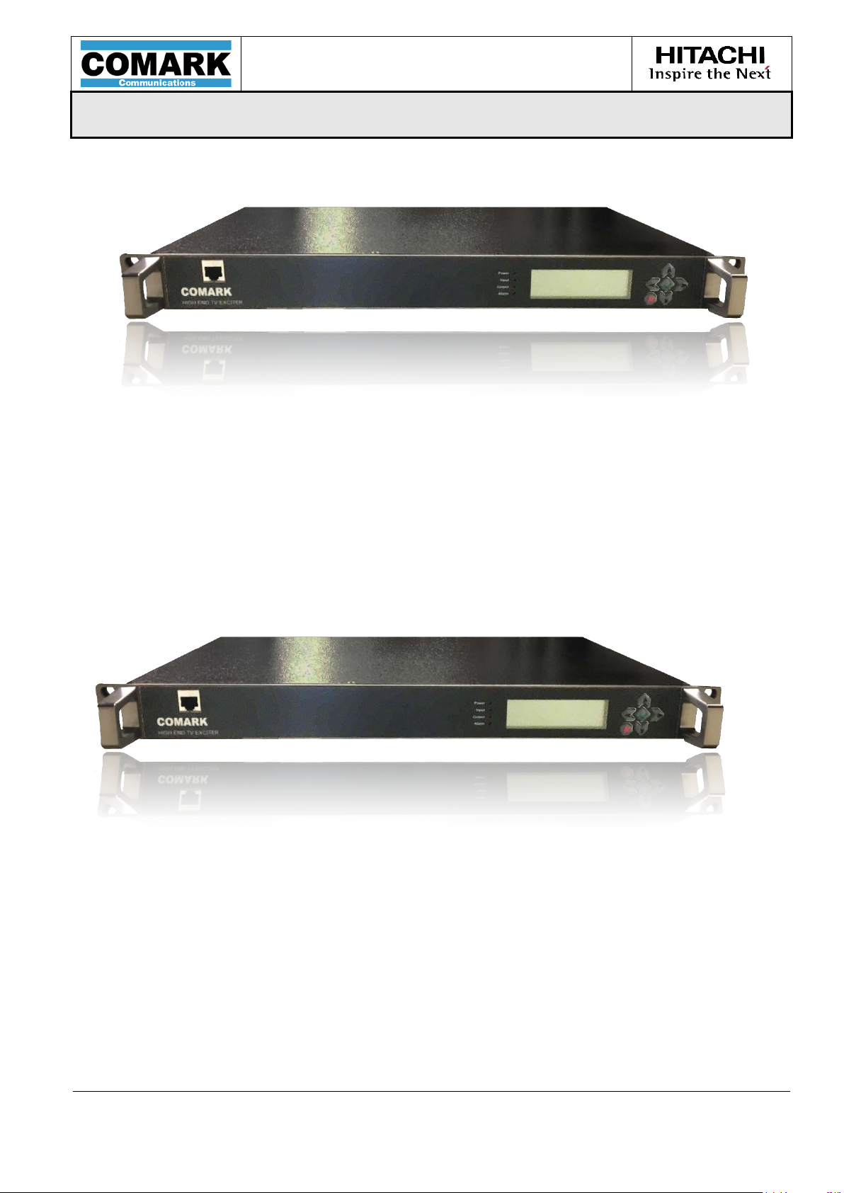
Below is a depiction of the exciter’s front panel.
Figure 22: Front panel overview
The front panel is composed of an LCD screen display with six buttons: four navigation
buttons (up, down, left and right arrows), one “OK” green button and one
“Cancel/Return” red button.
This front panel display allows the user to monitor and control the main features of the
EXACT-V2 exciter. Advanced features need to be accessed via the Web GUI.
Four status LEDs are also available: Power, Input, Output and Alarm. For a detailed
description, refer to paragraph 3.3 ”Front Panel signalization (LEDs description)”.
MPD-1611291-A
Page 42
USER MANUAL
MPD-1611291-A
EXACT-V2 High End Rack Modulator / Exciter
3/10/2017
Page 42/94
Stream input interfaces
x 2
Function:
Primary & secondary Inputs
Standard:
SMPTE-310M & DVB-ASI
Name:
ASI/SMPTE_IN1 & ASI/SMPTE_IN2
Connector:
BNC Connector– Input impedance 75Ω
Type:
Input
Performance
Data Rate:
DVB-ASI: 80 Mbps maxi.
SMPTE-310M: 19 Mbps
Mode:
Burst or Packet mode (DVB-ASI)
Format:
DVB-ASI: 188/204 bytes
SMPTE-310M: 188 bytes
A Control Ethernet port is also available on the front panel.
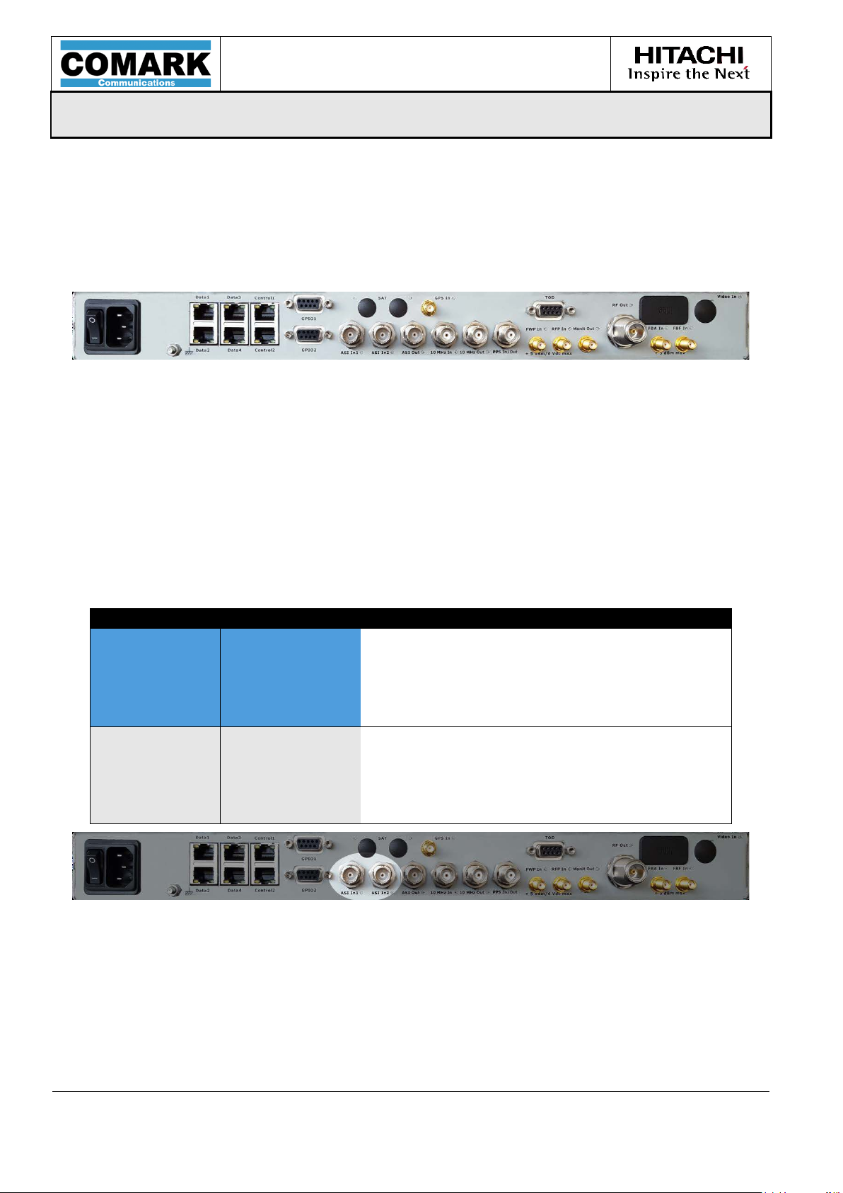
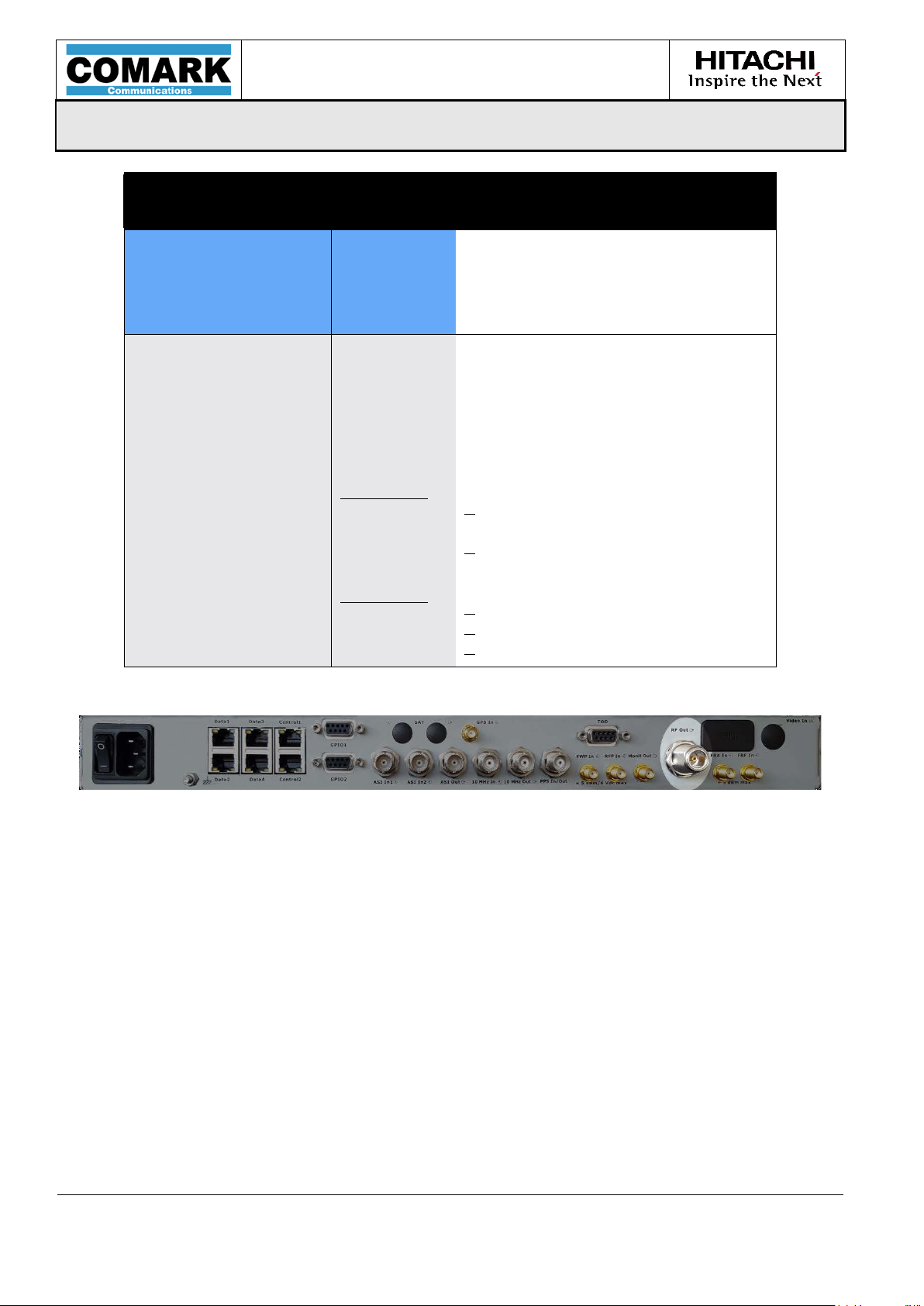
3.1.2 Rear Panel Layout
Below is a depiction of the exciter’s rear panel.
Figure 23: EXACT-V2 Rear panel o verview
The rear panel provides all the connectors needed for interconnection with the exciter.
Please refer to the next section for a detailed description.
3.2 Interface characteristics
The product interface are as follows:
General
Figure 24 ASI/SMPTE-310M Input interfaces
MPD-1611291-A
Page 43
USER MANUAL
MPD-1611291-A
EXACT-V2 High End Rack Modulator / Exciter
3/10/2017
Page 43/94
ASI Stream Output interface
x 1
Function:
ASI Output
Standard:
DVB-ASI
Name:
ASI_Out
Connector:
BNC Connector–impedance 75Ω
Type:
Output
Performances
Data Rate:
ASI: 80 Mbps maxi.
Mode/Format (Out):
Packet mode/188-byte
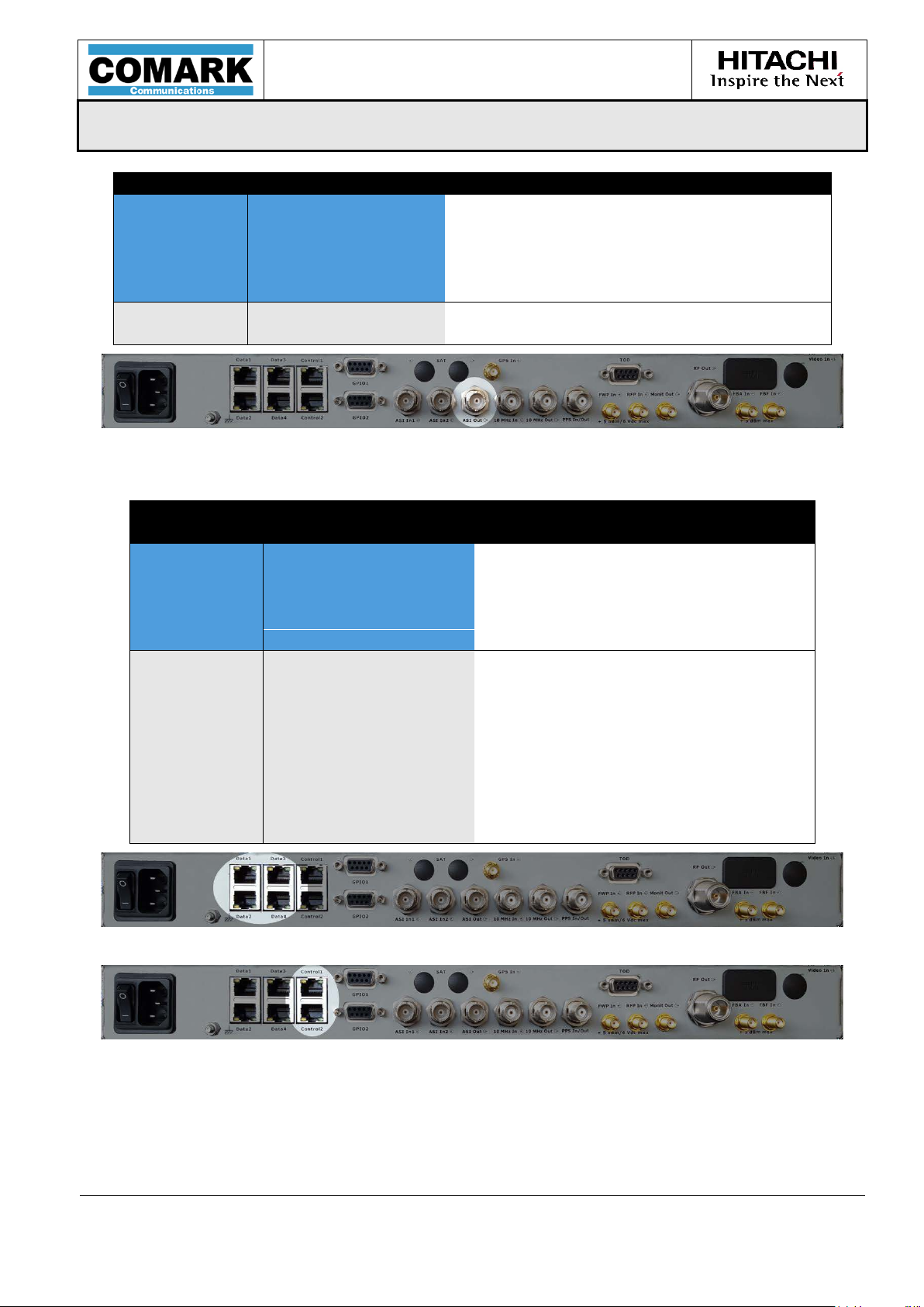
Electrical Gigabit Port
(Data & Control)
x 2
General
Function:
Gigabit Ethernet Port
Standards:
Ethernet, IP
Connector Name:
Gigabit1/Ctrl & Gigabit2
Connector Type:
RJ-45
Type:
Input/output
Performances
Data Rate:
1 Gbps max
Ethernet:
10/100/1000 Base T
Packet Type:
IPv4 – IPV6 Ready
Protocols:
IEEE802.3, IPv4, IPv6, XML, FTP,
SNTP
Jitter Tolerance:
50 ms
Mode:
Half/full duplex
Stream Encapsulation:
Accept IP and ALP formats (ATSC3.0)
FEC Decoding
SMPTE-2022 [I7 & I8]
General
Figure 25: ASI Output interface
Figure 26: Electrical Gigabit Data Interfaces
Figure 27: Electrical Gigabit Control Interfaces
MPD-1611291-A
Page 44

USER MANUAL
MPD-1611291-A
EXACT-V2 High End Rack Modulator / Exciter
3/10/2017
Page 44/94
GPS Antenna input
x1
General
Function:
GPS antenna input
Name:
GPS
Connector:
SMA
Type:
Input
Performances
Antenna Type:
Active
Antenna Voltage
3.3 VDC
Antenna System Gain:
10 dB
Frequency
1575.42 MHz
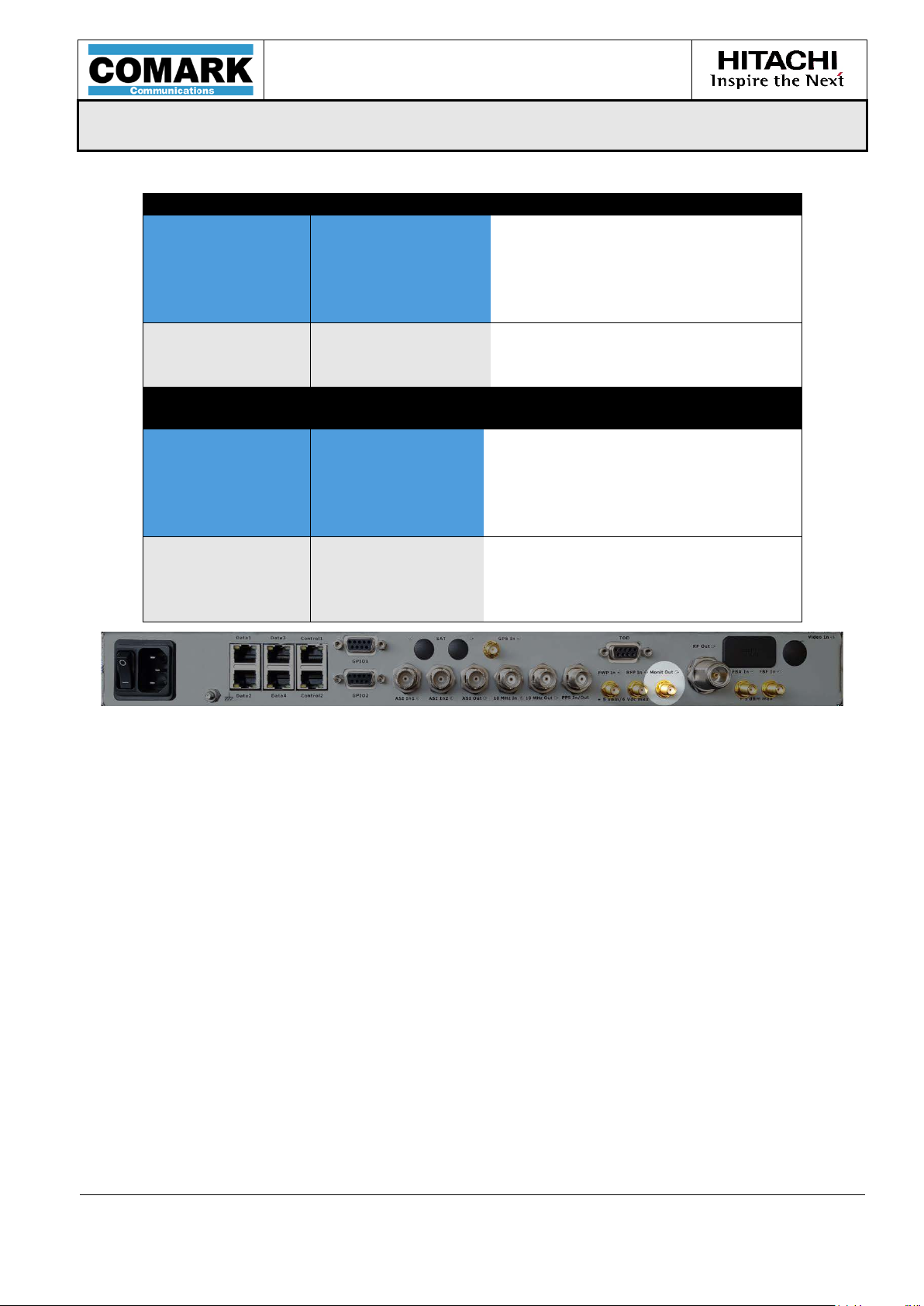
Clock reference input
x 1
General
Function:
Frequency referen ce input
Name:
10 MHz_IN
Connector:
BNC – 50 Ω
Type:
Input
Performances
Frequency:
10 MHz
Level:
From -15 to +15 dBm
Clock reference Output
x 1
General
Function:
10 MHz reference out p ut
Name:
10 MHz_OUT
Connector:
BNC – 50 Ω
Type:
Output
Performances
Frequency:
10 MHz
Level:
0 dBm ± 3 dB
Figure 28: GPS antenna input
Figure 29: Clock reference input
Figure 302: Clock reference output
MPD-1611291-A
Page 45

USER MANUAL
MPD-1611291-A
3/10/2017
Page 45/94
1PPS reference input/output
x 1
General
Function:
Time Reference in/ou t
Name:
1PPS
Connector:
BNC – 50 kΩ
Type:
Configurable I/O
Performances
Signal :
1 PPS
Level:
LVTTL / TTL (input)
LVTTL (output)
±50ns (input tolerance)
General
Function:
Type:
Performances
Frequency*:
*Specify UHF, VHF, or VHFB3 at time of order.
EXACT-V2 High End Rack Modulator / Exciter
Figure 31: 1PPS reference input/output
x 1
RF output
Standards:
Name:
Connector:
Bandwidth:
Level:
ATSC 1.0:
EVM:
Shoulders:
Spurious:
ATSC 3.0:
MER:
Shoulder:
Spurious:
ATSC 1.0 & ATSC 3.0
RF
N connector – 50 Ω
Output
VHF (54-88 MHz)
VHF (170-216 MHz)
UHF (470-862 MHz)
6 MHz
0 dBm
< 2.5% equalizer off
57 dB / 63 dB with precor
< -50dBc
> 40dB
> 40dB
< -50dBc
MPD-1611291-A
Page 46
USER MANUAL
MPD-1611291-A
EXACT-V2 High End Rack Modulator / Exciter
3/10/2017
Page 46/94
General
Function:
Type:
Performances
Frequency*:
Spurious:
RF Output (with OPT-20dB
Internal Preamplifier)
*Specify UHF, VHF, or VHFB3 at time of order.
X 1
RF output
Standards:
Name:
Connector:
Bandwidth:
Level:
ATSC 1.0:
EVM:
Shoulders:
Spurious:
ATSC 3.0:
MER:
Shoulder:
ATSC 1.0 & ATSC 3.0
RF
N connector – 50 Ω
Output
VHF (54-88 MHz)
VHF (170-216 MHz)
UHF (470-862 MHz)
6 MHz
+20 dBm
< 2.5% equalizer off
57 dB / 63 dB with precor
< -50dBc
> 40dB
> 40dB
< -50dBc
MPD-1611291-A
Figure 32: RF output
Page 47
USER MANUAL
MPD-1611291-A
EXACT-V2 High End Rack Modulator / Exciter
3/10/2017
Page 47/94
Monitoring Output
x 1
General
Function:
Monitoring output
Standards:
ATSC
Name:
Monit Out
Connector:
SMA – 50 Ω
Type:
Output
Performances
Frequency:
See RF Output
Level:
-20 dB (relative to RFout)
Other:
Monitoring Output (with OPT20dB internal preamplifer)
x 1
General
Function:
Monitoring output
Standards:
ATSC 1.0 / ATSC 3.0
Name:
Monit Out
Connector:
SMA – 50 Ω
Type:
Output
Performances
Frequency:
See RF Output
Level:
-43 dB (relative to RFout)
Other:
Monitoring signal from modulator
board (before amplifier)
Figure 33: Monitoring output
MPD-1611291-A
Page 48
USER MANUAL
MPD-1611291-A
EXACT-V2 High End Rack Modulator / Exciter
3/10/2017
Page 48/94
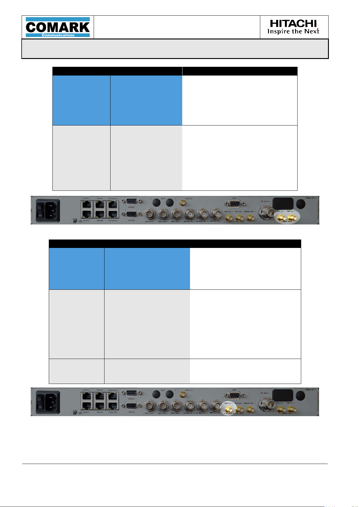
RF Feedback Inputs
x 2
General
RF Feedback inputs / RF
Measurements
Standards:
-
Name:
FBA / FBF
Connector:
SMA – 50 Ω
Type:
Input
Performances
UHF, VHF or VHF B3 depending
on model
Bandwidth:
75 MHz
Forward Power Measure Input/AGC
x 1
General
Function:
Forward Power Measure
Standards:
-
Name:
FWP In
Connector:
SMA – 50 Ω / High impedance
Type:
Input
Performances
Frequency:
Depends on model
Impedance:
50 Ω
Performances
Range:
0 to 5VDC
Precision:
0.01VDC typical
Impedance:
80 KΩ
Function:
(RF input)
Frequency:
Level:
Max input level:
Return loss:
Figure 34: Feedback inputs
Range:
-5 to -15 dBm
+5dBm (before damage)
>13dB
0 to -20dBm
Typical 0 to -10dBm
Precision:
Max input le v el:
Return loss: >12dB
(VDC input)
Figure 35: Forward Power Measurement / AGC input
MPD-1611291-A
0.5dB typical
+5dBm (before damage)
Page 49

USER MANUAL
MPD-1611291-A
EXACT-V2 High End Rack Modulator / Exciter
3/10/2017
Page 49/94
Reflected Power Measure Input
x 1
General
Function:
Reflected Power Measure
Standards:
-
Name:
RFP In
Connector:
SMA – 50 Ω / High impedance
Type:
Input
Performances
Frequency:
Depends on model
Impedance:
50 Ω
Performances
Range:
0 to 5VDC
Precision:
0.01VDC typical
Impedance:
80 KΩ
(RF input)
(VDC input)
Figure 36: Reflected Power Measurement input
Range:
0 to -10dBm
Precision: 0.5dB typical
Max Input Level: +5dBm (before damage)
Return Loss: >12dB
MPD-1611291-A
Page 50

USER MANUAL
MPD-1611291-A
EXACT-V2 High End Rack Modulator / Exciter
3/10/2017
Page 50/94
TOD
x 1
General
Function:
Control / monitoring
Standards:
1x RS-232
Name:
Serial Port 1
Connector:
Female SubD9
Type:
RS-232/RS-485
Performances
Control Baud rate:
TOD Baud rate:
9600 bps to 115200 bps
9600 bps
Other:
No parity, 8 bits data,
PIN
Name
Dir 1 RS232 Tx
Out
2
Rfu
3
TOD Rx
In
4
RS232 Rx
In
5
GND
6
RS485 Rx+
In
7
RS485 Rx-
In
8
RS485 Tx+
Out
9
RS485 Tx-
Out
Shield
GND
1 bit stop
The information containing Time Of Day (TOD) is available on Tekelec GPS with the following
characteristics:
• ASCII, 9600 bps, 8bits, 1 stop bit, no parity
• Protocole <message> <CR> <LF>
• Format day/year hour:minute:seconds e.g. 317/1996_18:16:20
The content of message should read “GPS reference” and not “UTC reference” or “local time”.
Figure 37: TOD/RS232 Port
MPD-1611291-A
Page 51

USER MANUAL
MPD-1611291-A
EXACT-V2 High End Rack Modulator / Exciter
3/10/2017
Page 51/94
Alarm
x 2
General
Function:
Alarm relays
Name:
GPIO / GPIO2
Connector:
SubD9 connectors
Type:
Dry contacts / GPI / VDC
in
/ VDC
out
PIN
Name
Dir
1
RELAY1_Normally_Open (Open when active alarm)
2
12 VDC output through 2.7 Kohms resistor and
protection diod e
3
RELAY2_COM
4
RELAY3_ Normally_Open (O pen when active alarm)
5
GND (cathode of the opto-coupler diode)
6
RELAY1_COM
7
RELAY2_ Normally_Open (O pen when active alarm)
8
Anode of the opto-c oupler diod e throu gh 330 ohms
resistor
9
RELAY3_COM
Shield
GND
PIN
Name
Dir
1
RELAY4_Normally_Open (Open when active alarm)
2
12 VDC output through 2.7 Kohms resistor and
protection diod e
3
RELAY5_COM
4
RFU
5
GND (cathode of the opto-coupler diode)
6
RELAY4_COM
7
RELAY5_Normally_Open (Open when active alarm)
8
Anode of the opto-coupler diode through 330 ohm s
resistor
9
RFU
Shield
GND
MPD-1611291-A
Figure 38 : Alarms Port
Page 52

USER MANUAL
MPD-1611291-A
EXACT-V2 High End Rack Modulator / Exciter
3/10/2017
Page 52/94
Name
Description
Green off: Primary input is not detected (in manual mode) or
Green static: Primary input is OK
Green off: no RF outpu t (module failure or mute condition)
Red flashing : RFP Critical Error
Off: No critical error detected
1PPS primary selection)
3.3 Front Panel signalization (LEDs description)
A set of 4 LED’s indicate the exciter status:
o A Power LED indicator
o An Input LED indicator
o An Output LED indicator
o An Alarm LED indicator
Behavior may differ depending on the exciter function and configuration.
Below is a description of the LED’s behavior:
Power
Green off: power off
Green static: power on
primary and secondary input is not detected (in auto mode)
Input
Green flashing: Primary input is OK
(1)
but secondary input is OK
(in auto mode)
(1)(4)
Green static: the RF output is available (normal mode)
(2)
Output
Green flashing: Test signal
Yellow static: Warning RFP or FWP
is generated or RF Maintain mode
Red static: Error RFP or FWP
Red static: Module failure
Alarm
Red flashing: Primary input failure
(5)
reference
loss (10 MHz or PPS in case of ext 10MHz + ext
Table 5: LED status
(3)
or primary clock
(1) If primary input is detected while any condition for "Mute on TS error" is met,
the input LED flashes.
(2) PRBS, Sine, or any special test.
(3) Except in case of PRBS or Sine tes t mode.
(4) In automatic mode, if primary input is detected, the input LED is fixed whatever
the secondary input status.
MPD-1611291-A
Page 53
USER MANUAL
MPD-1611291-A
EXACT-V2 High End Rack Modulator / Exciter
3/10/2017
Page 53/94
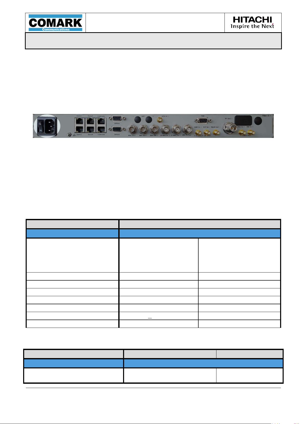
3.4 Power requirements
The exciter must be powered by a 110-240VAC 50-60Hz voltage.
The overall EXACT-V2 modulator consumes up to 70 W.
The overall EXACT-V2 exciter consumes up to 120 W with optional +20 dB preamp.
Figure 39: Power supply plug
A yellow/green ground cable (0.75mm² min) must be connected to the sm all connector
located between the power supply plug and the GPS antenna input. This cable must be
securely connected to the ground before switching on the equipment.
3.5 Performances and technical characteristics
3.5.1 General characteristics
Characteristics Typical Value Comment
Environment
Power Voltage:
Frequency Range:
Power Consumption:
Dimensions: 9.8” x 19” x 1.75”
Weight: 10 lbs
Operating Temperature: 0 °C to +50 °C
Storage Temperature: -10 °C to +70 °C
Storage Relative Humidity: 10 to 80 % at 50 °C
Operating altitude: < 2000m
Cleaning: Air cooling areas
3.5.2 Control and data Ethernet interfaces
Gigabit interf ac es Typical Value Comment
90 - 264 VAC
50-60 Hz
< 70 W
<120 W
EXACT-V2
EXACT-V2-20dB
Ethernet
Control Link
& :
MPD-1611291-A
10/100/1000 Base-T
Half / Full duplex
Page 54

USER MANUAL
MPD-1611291-A
EXACT-V2 High End Rack Modulator / Exciter
3/10/2017
Page 54/94
Data Link
Auto nego
IP Characteristics
Maximum Bit Rate: 100 Mbps
Number of Processed IP Streams: 1 per physical interface
Maxi Network Jitter Tolerance: 50 ms
Ethernet MTU Length: Max 1500 bytes In ATSC 1.0
Data De-Encapsulation
Protocol: TS / RTP / UDP / IP and
Pro-MPEG Cope 3 decoding
(compliant with SMPTE 2022-1-2007
and SMPTE 2022-2-2007)
TS Packet Number per IP Packet: 1 to 7 User configurable
FEC Decoding: SMPTE 2022
FEC Type: SMPTE 2022
FEC Matrix (L,D)/(LxD) : SMPTE 2022
MPEG-TS Packet Length: 188 bytes
3.5.3 Serial control interfaces
Control interf ac e s Typical Value Comment
RS232
Standard:
Electrical Level: ± 12 v compatible
Baud Rate: 9600 bauds to 115200 bauds
Others: No parity, 8 bits data, 1 bit stop
Connector: SuB-D9 specific pinout with RS485
RS232
and TOD interfaces
TX and RX signals only.
Limited to the use for “TX
control” part (do es not
fully control the exciter)
TOD is RFU in ATSC1.0
RS485
Standard:
Electrical Level: RS485 compatible
Baud Rate: 9600 bauds to 115200 bauds
Others: No parity, 8 bits data, 1 bit stop
Connector: SuB-D9 specific pinout with RS232
RS485 Full or Half duplex
and TOD interfaces
TX and RX signals only.
Limited to the use for “TX
control” part (do es not
fully control the exciter)
MPD-1611291-A
Page 55
USER MANUAL
MPD-1611291-A
EXACT-V2 High End Rack Modulator / Exciter
3/10/2017
Page 55/94
TS Stream switc hing:
IP CleverSwitch:
Automatic or manual
Between prim. & sec. IP strea m
With auto or manual switch-back
Not seamless
TOD
Standard:
Electrical Level: ± 12 v compatible
Baud Rate: 9600 bauds
Others: No parity, 8 bits data, 1 bit stop
Connector: SuB-D9 specific pinout with RS232
and RS485 interfaces
RS232
Limited to RX signal
3.5.4 AS I inputs / outp ut and MPEG-TS proce ssing
TS stream Typical Value Comment
ASI / SMPTE Inputs
Format: TS/DVB-ASI or TS/SMPTE-
310M
Packet Size: 188/204 bytes - Packet or
Burst mode
188 bytes
Maximum Useful Bit Rate: 19.39 Mbps DVB-ASI / SMPTE-310M
Max. Input Jitter: +/- 100 ms
Input Impedance: 75 ohms
Return Loss: > 15 dB up to 270 MHz
DVB-ASI
SMPTE-310M
TS or T2-MI Processing
TS CleverSwitch:
TS processing NIT update
Between primary & sec. stream
Bit rate adaptation
PCR re-stamping
ASI Output
Format: TS over DVB-ASI
Packet Size: 188 byte
188 byte
Maximum Useful Bit Rate: 19.39 Mbps
19.39 Mbps
Max. Output Jitter: Same as incoming jitter
Not seamless
Carrier Frequency update
DVB-ASI
SMPTE-310M
DVB-ASI
SMPTE-310M
MPD-1611291-A
Page 56

USER MANUAL
MPD-1611291-A
EXACT-V2 High End Rack Modulator / Exciter
3/10/2017
Page 56/94
o the total power of the
Amplitude Ripple:
≤ 0.2 dB typical
Group Delay Ripple:
≤ 20 ns typical
Pilot Carrier Phase Noise:
≤ -104 dBc/Hz @ 20 kHz up to
700 MHz
PAPR
Protection Clipping:
8 to 20 dB (0.1 dB step)
3.5.5 Digital modulation
Characteristics Typical Value Comment
ATSC Modulation
ATSC Mode: 8VSB According to ATSC A/53
Channel Bandwidth: 6 MHz
Characteristics Typic al Value Comment
Modulation Performances
In Band SNR (Eq. OFF):
EVM (Eq. OFF):
MER (Eq. OFF):
MER (Eq. ON):
Shoulder and Out of Band
Rejection:
≥ 57 dB / ≥ 63 dB with precor
Spurious: ≤ -50 dBc Relative t
≥ 30 dB
≤ 2.0%
≥ 30 dB
≥ 45 dB
≥ 63 dB
≥ 63 dB typical
From pilot level
EXACT-V2
EXACT-V2-20dB at +20 dBm
EXACT-V2-20dB at +17 dBm
signal at nominal output p ower
Configuration Range:
Pre-clipping Optimization:
Characteristics Typic al Value Comment
Miscellaneous
Automatic Mute:
RF Maintain: Configurable on stream errors
Spectrum Reverse: Configurable
Test Modes: Single sine tone / +6 dB Sinus
8 to 20 dB (0.1 dB step)
0 to 255
Configurable on stream errors
Configurable on clock errors Configurable T im eout (LORS)
PRBS
MPD-1611291-A
Page 57

USER MANUAL
MPD-1611291-A
EXACT-V2 High End Rack Modulator / Exciter
3/10/2017
Page 57/94
Impedance:
Level:
Frequency:
Level:
Min Pulse Width:
Level:
Pulse Width:
System:
Frequency:
Max Nb of Tracked Sat.:
Antenna System Gain:
Sensitivity:
PPS Accuracy:
Antenna Power Supply:
3.5.6 Clo c k synchroniz ation
Characteristics Typical Value Comment
External References
External 10 MHz Reference Input
50 Ohms
External 1 PPS Reference Input
10 MHz Reference Output: 0 dBm ± 3 dB
1 PPS Reference Output
-15 to +15 dBm
10 MHz ± 0.6 ppm
LVTTL level – 5 kohms
1 µs
LVTTL
≥ 100 ns
Characteristics Typical Value Comment
GPS Synchronization
GPS
1575.42 MHz
12
10 dB
<-138 dBm
± 50 ns
3.3 Volts DC
Characteristics Typic al Value Comment
MPD-1611291-A
Page 58

USER MANUAL
MPD-1611291-A
EXACT-V2 High End Rack Modulator / Exciter
3/10/2017
Page 58/94
T°fStabilityf(Full
Temperature Range):
Tuning:
Short Term Stability:
Aging:
External_10MHz_Locked:
External_10MHz_Unlocked:
Onboard GPS_Locked:
Onboard GPS_Unlocked:
Guaranteed from 470 MHz
Characteristics Typical Value Comment
Clocks & Synchronization
10 MHz Lock Control Type: Digital
Internal 10 MH z c loc k With OCXO
< ± 5.10-9
0 50 °C
Synchroniza tion Cases Stability Aging
Output Phase Noise: < -104 dBc/Hz @ 20 kHz
< ± 3.10
< ± 3.10
< ± 7.10
< ± 7.10
< ± 0.6 ppm
< ± 1.10
< ± 5.10
< ± 7.5.10
< ± 5.10
-10
-
-10
< ±7.5.10-8 /
-10
-
-10
< ±7.5.10-8 /
-11
Over 1 s, 10 s
-10
/ day
-8
/ year
-7
/ 15 years
year
< ±5.10-10 / day
year
< ±5.10-10 / day
Internal
Internal
to 700MHz
MPD-1611291-A
Page 59

USER MANUAL
MPD-1611291-A
EXACT-V2 High End Rack Modulator / Exciter
3/10/2017
Page 59/94
Accuracy:
Output Level:
(Relative to Main Output)
-40 dB ± 2 dB
EXACT-V2
EXACT-V2-20dB
EXACT-V2
EXACT-V2-20dB
3.5.7 RF and monitoring outputs
Characteristics Typical Value Comment
RF Output
Adjustable Frequency
Impedance: 50 ohms
Range:
Step Size:
Main Signal:
Stability:
Return Loss:
Attenuation Range:
Attenuation Step:
Monitoring Signal:
470 to 862 MHz
170 to 240 MHz
54 to 88 MHz
1 Hz
0.2 Hz
0 dBm ± 1 dB
+20 dBm ± 1 dB
± 0.1 dB / 10 °C
> 13 dB
> 12 dB
0 to 17 dB
0.1 dB
-20 dB ± 2 dB
EXACT-V2
EXACT-V2-20dB
EXACT-V2-20dB
EXACT-V2
EXACT-V2-20dB
MPD-1611291-A
Page 60

USER MANUAL
MPD-1611291-A
EXACT-V2 High End Rack Modulator / Exciter
3/10/2017
Page 60/94
RF Frequency Band:
Impedance:
Return Loss:
Nominal Input Level:
Max Input Level:
Adjacent Channel Rejection:
Linear Precorrection:
Group Delay:
32 points
± 500 ns (10 ns step)
Linear Adaptive Precorrection
Group Delay:
± 500 ns (10 ns step)
Non-Linear Adaptive Precorrection
AM/PM:
± 25° (0.2° step)
RF Feedback Input Levels:
Bar graph 0-100 %
Left and Right Shoulders:
On FBA or FBF input
> 45 dB max
Resolution 1 dB
MER:
On FBA or FBF input
The MER measurement
should not be used as an
only for variation detection.
3.5.8 Digital precorrection
Characteristics
Feedback Inputs
Typical Value Comment
470 to 862 MHz
170 to 240 MHz
54 to 88 MHz
50 ohms
> 13 dB
-5 to -15 dBm
+5 dBm (before damage)
No adjacent channel support
Characteristics
Manual Precorrection
Adaptive Precorrection
Amplitude:
Amplitude:
± 3 dB (0.1 dB step)
± 3 dB (0.1 dB step)
Typical Value Comment
On the overall bandwidth
AM/AM:
± 6 dB (0.05 dB step)
Characteristics
DAP Performances Measurement
Typical Value Comment
For relative us e only
From 20 up to 40 dB Typical
absolute value. It can be used
MPD-1611291-A
Page 61
USER MANUAL
MPD-1611291-A
EXACT-V2 High End Rack Modulator / Exciter
3/10/2017
Page 61/94
AC Impedance:
50 ohms
DC Impedance:
~ 80 kohms
Return Loss:
> 12 dB
Nominal Input Level:
-10 to 0 dBm
0 to 5 Vdc
In RF power mode
In DC voltage mode
Maximum Input Level:
+5 dBm / 6Vdc
Accuracy:
0.5 dB typical
In RF power mode
calibration
Max Input Level:
+5 dBm (before damage)
Reactivity Time:
1 s max
Measurement Bandwidth:
Full bandwidth
Configurable Coupler Gain:
0 to +100.0 dB
Gain Step:
0.1 dB
Configurable Probe Offset:
-32768 mV to +32767 mV
Offset Step:
1 mV
Configurable Probe Slope:
-100.00 to +100.00 dB/V
0 to +65535 mW/V
for VDC/dBm type
for VDC/W type
Slope Step:
0.01 dB/V
1 mW/V
for VDC/dBm type
for VDC/W type
Maximum AGC Gain:
0 to 20.0 dB
Maximum AGC Gain Step:
0.1 dB
Nominal Power Level:
-100.0 to 100.0 dBm
Nominal Power Level Step:
0.1 dB
Maximum Switching Voltage:
25 Vac / 60 Vdc
Maximum Switching Current:
1 A
Maximum Switching Power:
62.5 VA / 30 W
Available Contacts:
Normally open
Normally close
3.5.9 Power level measur ement inp uts and AGC
Characteristics Typical Value Comment
Measurement Inputs
(Forward and Ref lected Power)
0.01 Vdc
Measurement Calibration
-32768 to +32767 mVrms/V
In DC voltage mode
May require significant
for VDC/Vrms type
1 mVrms/V
AGC
3.5.10 Dry contacts
Characteristics Typical Value Comment
Relay characteristics
for VDC/Vrms type
MPD-1611291-A
Page 62

USER MANUAL
MPD-1611291-A
EXACT-V2 High End Rack Modulator / Exciter
3/10/2017
Page 62/94
3.6 Conformity with EC Directive
The CE marking is present on the RTM-50 product. It:
• Shows that we have checked that this product meets safety, health or
environmental requirements
• Is an indication of a product’s compliance with legislation
• Allows the free movement of products within the market
By placing the CE marking on our product we are declaring, on our own responsibility,
conformity with all of the legal requirements to achieve CE marking.
MPD-1611291-A
Page 63

USER MANUAL
MPD-1611291-A
EXACT-V2 High End Rack Modulator / Exciter
3/10/2017
Page 63/94
4 EXACT-V2 Installation
MPD-1611291-A
Page 64

USER MANUAL
MPD-1611291-A
EXACT-V2 High End Rack Modulator / Exciter
3/10/2017
Page 64/94
MPD-1611291-A
Page 65

USER MANUAL
MPD-1611291-A
EXACT-V2 High End Rack Modulator / Exciter
3/10/2017
Page 65/94
Figure 40
Notes:
Installation must be performed by a qualified individual following the
CEI60728-11: 2005 directive.
4.1 Unpack the Unit
Please check the shipping container for any damage due to transportation when
receiving the product. If there is any damage please contact the carrier immediately.
Carefully unpack the exciter from the storage box.
Check the exciter for any damage due to transportation.
Save the box and foam packaging in c ase the system needs to be shipped to another
location or returned for repair.
4.2 Installation and Recommendations
Install the unit in the appropriate location using four, rack-mounting screws (not
included) as shown in the following figure:
: Chassis installation
• Mechanical mounting into a rack must take into account any
overloading to the mounting ears of the chassis to avoid danger.
•
Rack connection to power supply must be taken into account for any
electrical overload protection. A specific electrical study must be
performed by integrator/installer.
• The equipment must be connected to power supply with a ground
connection. Groun d connection of the eq u i p ment must be checked b efore
use.
•
MPD-1611291-A
Page 66
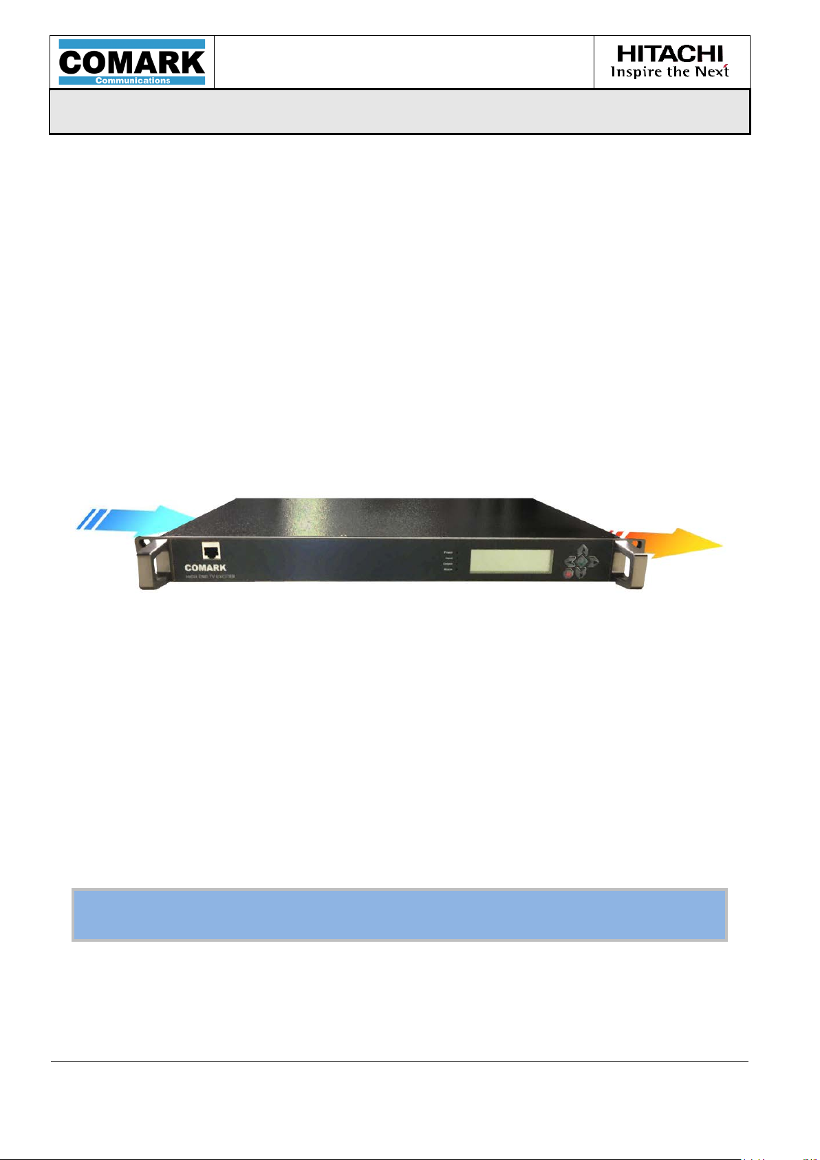
USER MANUAL
MPD-1611291-A
EXACT-V2 High End Rack Modulator / Exciter
3/10/2017
Page 66/94
Figure
Notes: The power supply connector must remain available to easily
disconnect the equipment in case of emergency.
4.2.1 Temperature alarms
The maximum temperature levels are as follows:
o A warning will be raised when the internal temperature reaches higher than 68°C
o An alarm with o utput muting will trigger after internal temperatures reach higher
than 71°C
In both cases, the normal status conditions return when the temperature falls below
67°C.
4.2.2 Cooling methods
Specific care must be taken concerning the cooling system. The following figure shows
air flow due to internal fans. When the unit is integrated in an equipment cabinet,
sufficient space must be left on the right and left s id e of the unit to allow suf ficient air
flow.
41: Rack air fl o w
4.3 Wiring and Powering on
Once fixed in a location, the exciter can be wired depending on its configuration.
When powered ON, the exciter is fully operationa l after a few se conds. Please refer to
section 3.3 for a front panel LED diagnostic.
To simply control and monitor the EXACT, any web browser can be used with an IP
connection between the exciter and the PC. The default IP address is 192.168.0.209
on IP port #1. The control port #1 IP configuration can be retrieved/modified using
the front panel menu.
MPD-1611291-A
Page 67

USER MANUAL
MPD-1611291-A
EXACT-V2 High End Rack Modulator / Exciter
3/10/2017
Page 67/94
4.4 Initial Configuration
Except otherwise specified at the time of order, the exciter is delive red with the basic
configuration as described hereafter. T he following configuration can also be retrieved
with the “Set Default” comman d (not available in the WEB GUI) that wil l only keep IP
settings and precorrection curves.
IP Parameters Default Settings
Ethernet Mode: Auto-sensing
DHCP Disabled
Gig abit#1 Configuration:
(not changed by default command)
Gigabit#2 SNMP
(not changed by default command)
Gigabit#7 Front Pa nel Control
Gigabit #3, #4, #5, #6 Input
(not changed by default command)
Gigabit#3 Input
(not changed by default command)
Gigabit#4 Input
(not changed by default command)
Gigabit#5 Input
(not changed by default command)
Gigabit#6 Input
(not changed by default command)
Time Out
MAC address: module unique address
Address: 192.168.0.209
Subnet: 255.255.255.0
Gateway: 192.168.0.254
DHCP: OFF
MAC address: module unique address
Address: 192.168.0.211
Subnet: 255.255.255.0
Gateway: 192.168.0.254
DHCP: OFF
MAC address: module unique address
Address: 192.168.0.210
Subnet: 255.255.255.0
Gateway: 192.168.0.254
DHCP: OFF
MAC address: Port#2 unique address
Address: 192.168.1.210
Subnet: 255.255.255.0
Gateway: 192.168.1.254
MAC address: Port#2 unique addr ess
Address: 192.168.1.211
Subnet: 255.255.255.0
Gateway: 192.168.1.254
MAC address: Port#2 unique address
Address: 192.168.2.210
Subnet: 255.255.255.0
Gateway: 192.168.2.254
MAC address: Port#2 unique address
Address: 192.168.2.211
Subnet: 255.255.255.0
Gateway: 192.168.2.254
1 sec.
Table 9: Default IP settings at the delivery
MPD-1611291-A
Page 68

USER MANUAL
MPD-1611291-A
EXACT-V2 High End Rack Modulator / Exciter
3/10/2017
Page 68/94
ATSC 1.0
Other Parameters Default Settings
Standard:
ASI/SMPTE_IN1 Equalizer* : Disabled
ASI/SMPTE_IN2 Equalizer* : Disabled
Major Channel number update: Disable
Carrier Frequency for Carrier Frequency
Center Frequency (ATSC) *: 665 MHz (channel 46)
Output Attenuation (AT S C) *: 0 dB
(not changed by default command)
Test Mode: Disabled
Serial Speed: 57600
Serial Protocol: Standard
Auto Logout Time: Off
ASI/SMPTE_IN1 Type: ASI
ASI/SMPTE_IN2 Type: ASI
Primary Source: ASI/SMPTE_IN1
Secondary Source: ASI/SMPTE_IN2
ASI Output OFF
TS CleverSwitch:
Auto_Switch_Back:
Packet error threshold:
Packet valid threshold:
ATSC signalization: 8-VSB
ASI mana ge me nt unit
(Bit rate adaptation):
Major Channel number: 0
Carrier Frequency update: Disable
Update:
Bandwidth: 6 MHz
Crest Factor: 10.0 dB
Crest Factor O ptimization: 0
Protection Clipping: 15 dB
Spectrum Inversion : No
RF Output Monitoring: Enabled
Exciter RF Failure Offset: 5.0 dB
Starting Delay 5 seconds
AGC Off
AGC Maximum Gain 0 dB
AGC Response Time Nominal
ATSC
Enabled
Disabled
80000
Enable
665 MHz
5
MPD-1611291-A
Page 69

USER MANUAL
MPD-1611291-A
EXACT-V2 High End Rack Modulator / Exciter
3/10/2017
Page 69/94
Mute Conditions: GPI=0: Disabled
GPI=1: Disabled
Mute: Disable
RFP Warning AGC Protection: Disabled
RFP Error Protection Cycle: Disabled
RFP Error Protection – No. of Retries: 3
RFP Error Protection – Delay Between
Retries:
RFP Error Protection – Cycle Reset
Time:
RF Maintain: On Input Stream Error: Enabled
Enable Down-Converter: Enabled
DAP Mode: Off (standar d)
Linear Precorrection Circuits* :
Non-Linear Precorrection circuits* :
Linear DAP Mode:
Non-Linear DAP Mode:
Static (DAP is disabled)
Static (DAP is disabled)
Linear DAP Time_Out:
Non-Linear DAP Time_Out:
Primary Clock: Internal
Secondary Clock: Internal
PPS Source: Onboard GPS
PPS Interface: Output
PPS Edge (RFU): Rising
Warm-Up Time (Before 10 MH z
Synchro):
GPS Antenna Voltage: 3.3 VDC
Absolute Reference Time: GPS
Time and Date Setting: Manual
Power Measurements:
(not changed by default command)
FWP Input Type:
(not changed by default command)
FWP Coupler Attenuation:
(not changed by default command)
Nominal Power:
(not changed by default command)
Min FWP Error:
(not changed by default command)
Min FWP Warning:
(not changed by default command)
Max FWP Warning:
(not changed by default command)
Disabled (Bypassed)
Disabled (Bypassed)
4
60
20 min
10 min
Enabled
Active
RF input
0 dB
0 dBm
80 %
90 %
110 %
MPD-1611291-A
Page 70

USER MANUAL
MPD-1611291-A
EXACT-V2 High End Rack Modulator / Exciter
3/10/2017
Page 70/94
Max FWP Error:
(not changed by default command)
RFP Input Type:
(not changed by default command)
RFP Coupler Attenuation:
(not changed by default command)
Max RFP Warning:
(not changed by default command)
Max RFP Error:
(not changed by default command)
Dual-Drive Redundancy: Disabled
GPO2 Opening Triggers: None
GPO3 Opening Triggers: Output error
RF Switch Monitoring: Disabled
Transmitter Control: Disabled
*Note: different set of parameters are used for Single Carrier modulation (ATSC) and
OFDM modulation (future ATSC 3.0) in regards to their:
o Frequency (Carrier frequency in ATSC // Center frequency in ATSC 3.0)
o Attenuation
o Gain offset
o Linear Precorrection activation (with separate curves banks)
o Non-Linear Precorrection activation (with separate curves banks)
* Note: On the WEB GUI, the input equalizer is automatically changed to « disabled » whe n the
user selects the « SMPTE » input type.
ATSC 3.0 (Available from the S110 firmware version)
120 %
RF input
0 dB
10 %
20 %
Alarm error
MPD-1611291-A
Page 71

USER MANUAL
MPD-1611291-A
EXACT-V2 High End Rack Modulator / Exciter
3/10/2017
Page 71/94
5 Operation
MPD-1611291-A
Page 72

USER MANUAL
MPD-1611291-A
EXACT-V2 High End Rack Modulator / Exciter
3/10/2017
Page 72/94
MPD-1611291-A
Page 73

USER MANUAL
MPD-1611291-A
EXACT-V2 High End Rack Modulator / Exciter
3/10/2017
Page 73/94
Figure 42
V2 IP connection
5.1 Operation Generalities
5.1.1 Local Operation
The product can be locally controlled using the front panel menu. It is composed of an
LCD screen and 6 buttons to navigate the control/monitoring menu.
The primary features are available using the front panel but for complete access to the
unit, please use the w eb G UI.
5.1.2 Remote Operation
The product can be controlled using any web browser. It allows the user to control,
monitor, and maintain the unit.
Below are the system requirements:
• PC using a Pentium 1GHz or higher microprocessor
• Microsoft Windows Vista/XP or Windows 2000 Service Pack 3 or later
• 1024 x 768 resoluti on (or h igher) video adapter
• Minimum of 128 MB of RAM (256 MB recommended)
• 120 MB of disk space
• A Microsoft-compatible mouse
: EXACT-
The web GUI can be accessed via any web browser using the IP address of the unit. By
default, this address is 192.168.0.209. The IP address can be retrieved/modified using
the front panel menu.
MPD-1611291-A
Page 74
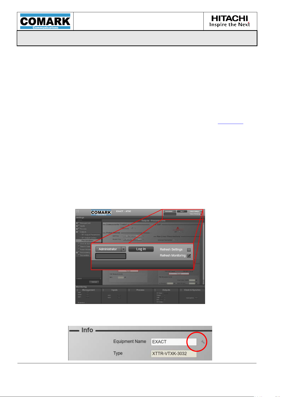
USER MANUAL
MPD-1611291-A
EXACT-V2 High End Rack Modulator / Exciter
3/10/2017
Page 74/94
5.2 Embedded Web GUI Description
5.2.1 Requirements
To connect to the EXACT-V2 web interface, a web browser with Flash Player is
mandatory.
5.2.2 Connection to EXACT-V2
Using the web browser, the user will access the modulator by typing “http://[IP
where [IP] is the IP address of the equipment. This address can be retrieved using the
front panel display menu: MANAGEMENT > Control IP Port > Add
To access any settings of the EXACT-V2 unit, a login is required. There are 3 logi ns:
o User (Guest): Only mo nitoring of the equipment is allowed
o Maintenance: M inor changes are allowed like test mode, input management,
precorrections, mute/unmute, clock and synchronization, etc.
o Administrator: Complete access to the equipment
To login, the user will choose their access level, type the password and click on the
“Login” button. There is no password for the “Guest” account. Both the “Administrator”
and “Maintenance” accounts have the same password: admin
]”,
Depending on the granted access level, each parameter that can be modified by the
user will be followed by a small “tool” icon.
MPD-1611291-A
Page 75
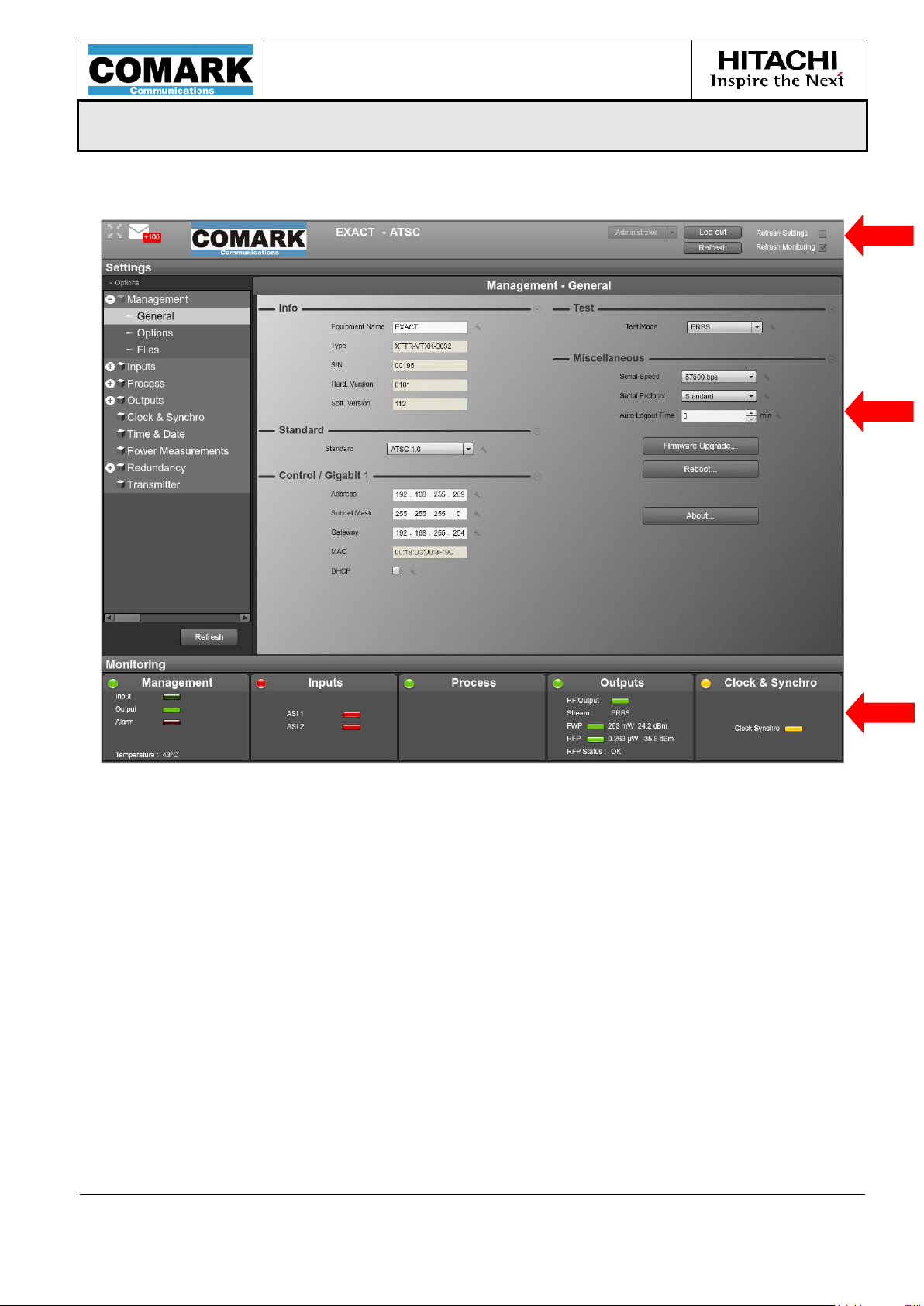
USER MANUAL
MPD-1611291-A
EXACT-V2 High End Rack Modulator / Exciter
3/10/2017
Page 75/94
1
2
5.2.3 General Overview
Area 1 is the header of the main window. It presents the login/logout functions as well
as equipment identification.
Area 2 is the main window. It pres ents eithe r the parameters se ttings or the de tailled
monitoring.
Area 3 is the “Status Overview” area. It presents an overview of the main status.
3
MPD-1611291-A
Page 76

USER MANUAL
MPD-1611291-A
EXACT-V2 High End Rack Modulator / Exciter
3/10/2017
Page 76/94
5.2.4 Settings Tab
The Settings tab can be accessed by clicking on the « Settings » header.
The left part of the screen describes the settings menu while the right part presents
each screen related t o on e menu item.
When any parameter is changed, it is highlighted.
MPD-1611291-A
Page 77
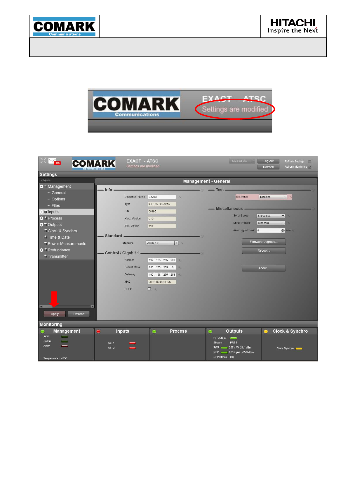
USER MANUAL
MPD-1611291-A
EXACT-V2 High End Rack Modulator / Exciter
3/10/2017
Page 77/94
A message in the main window he ader allows the user to verify if the sett ings have
been modified and not applied.
The Apply button appears to confirm the application.
If any change must be discarded, the « Refresh » button can be used to display the
current configuration in the settings screens.
MPD-1611291-A
Page 78

USER MANUAL
MPD-1611291-A
EXACT-V2 High End Rack Modulator / Exciter
3/10/2017
Page 78/94
5.2.5 Monitoring Tab
The Monitoring tab can be accessed clicking on the Monitoring header.
It is divided into 2 independent screens to allow the user to monitor two different
blocks.
To select a block to monitor, a Drag and Drop feature can be used from the “Status
Overview” area to on e of the two areas.
MPD-1611291-A
Page 79
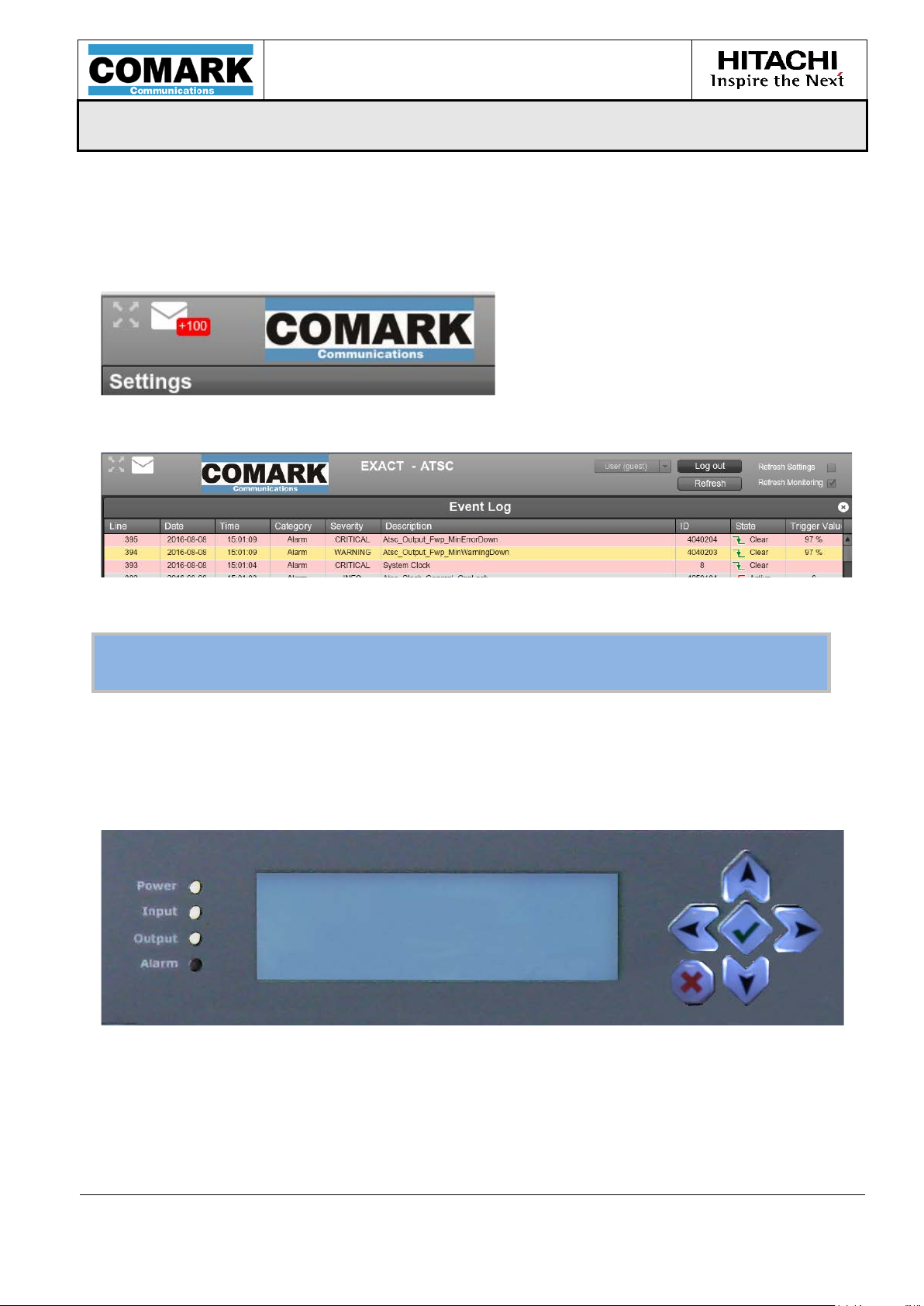
USER MANUAL
MPD-1611291-A
EXACT-V2 High End Rack Modulator / Exciter
3/10/2017
Page 79/94
Notes:
Application Note.
5.2.6 Log File
EXACT-V2 features an onboard Log file to consult the different information, warning
or error that occurred on the product.
To access to the Log File window, please press the envelop.
Then the log file window is displayed.
For more information concerning this topic, please refer to the dedicated
5.3 Front Panel Menu Description
Main settings can be accessed from the EXACT-V2 front panel display (FPD).
Menu navigation is done using the keypad on the right side of the LCD screen.
MPD-1611291-A
Page 80

USER MANUAL
MPD-1611291-A
EXACT-V2 High End Rack Modulator / Exciter
3/10/2017
Page 80/94
MPD-1611291-A
Page 81

USER MANUAL
MPD-1611291-A
EXACT-V2 High End Rack Modulator / Exciter
3/10/2017
Page 81/94
6 Maintenance
& Troubleshooting
MPD-1611291-A
Page 82

USER MANUAL
MPD-1611291-A
EXACT-V2 High End Rack Modulator / Exciter
3/10/2017
Page 82/94
MPD-1611291-A
Page 83

USER MANUAL
MPD-1611291-A
EXACT-V2 High End Rack Modulator / Exciter
3/10/2017
Page 83/94
6.1 Versions management
The product is defined by its commercial reference and its version numbers.
Product versions are managed using two separate and independent three digits
numbers:
• The hardware version
• The software version
The version of the pr od u c t is defined for example as: ............... H100-S112
This means that the hardware of the product is in version 1.00 and the software is in
version 1.10.
These version ID’s can be read from the Web GUI.
6.2 Software updates
Software updates can be made by the user. New software can be provided by the
Hitachi-Comark customer service depart.
To request the latest updates, please contact our Customer Service Department by
sending an email to service@comarktv.com or by calling 800-345-9295.
For each software version available, a unique file (“customer pack”) has to be provided
by Hitachi-Comark. It is labeled as EXACT-H100-S112.zip, where EXACT-V2 is the
commercial reference of the product to wh ich it applies to, H100 giv es the m inimum
hardware version required by this new software version, and S100 is the new software
version
This customer pack contains:
o The firmware for ftp download (IP connection) referred to as EXACT-3000-
S0100-B0301.tfw
o The Upgrade Procedure (.pdf file) explaining how to perform the update
o The release notes
o The User Manual
o Any additional software, if needed
The software upgrade is done using the Web GUI of the product:
o Copy the *.tfw file on your local hard disk.
o Access to the web GUI and go to “Management / General” tab.
o Click on the “Firmware Upgrade” button
o Select the new release file on your local hard di sk.
The product will then automatically reboot to take into account the new release.
MPD-1611291-A
Page 84

USER MANUAL
MPD-1611291-A
EXACT-V2 High End Rack Modulator / Exciter
3/10/2017
Page 84/94
Name
Description
Green off: Prim ary input is not detected (in manual mode) or
Green fixed: Primary input is ok
Off: No critical error detected
1PPS primary selection)
6.3 Licence key management
New licences for either TS OIP or SNMP may be purchased separately and added to
the exciter. For this purpose:
o Access the web GUI and go to the “Management / Options” tab
o Select the desired option to unlock by clicking on the associated “Unlock” button
o Enter the key code that is provided by Hitachi-Comark following the licence order
The product then automatically reboots and the new licence is taken into account.
6.4 Troubleshooting of the exciter
6.4.1 LED Check
If the exciter does not work properly, a few checks could be done before calling the
technical support team at Hitachi-Comark.
A set of 4 LEDs indicates the modulator status fo llow ing the Hitachi-Comark standard,
Power, Input, Output and Alarm LED indicators.
Power
Green off: power off
Green fix: power on
primary and secondary input is not detected (in auto mode)
Input
Green flashing: Primary input is OK
(1)
but secondary input is OK
(in auto mode)
(1)(4)
Green off: no RF outpu t (module failure or m ute condition)
Output
Green fixed: the RF output is available (normal mode)
(2)
Green flashing: Test signal
is generated or RF Maintain mode
Red fixed : Modul e failure
Alarm
Red flashing : Primary input failure
(5)
reference
loss (10 MHz or PPS in case of ext 10MHz + ext
Table 10: LED Analysis
(3)
or primary clock
(1) If primary input is detected but any condition for "Mute on TS error" is met, the
input LED is flashing.
(2) PRBS, Sine, or any special test.
(3) Except in case of PRBS or Sine tes t mode.
(4) In automatic mode, if the primary input is detected, the input LED is fixed at
whatever the secondary input status is.
MPD-1611291-A
Page 85

USER MANUAL
MPD-1611291-A
EXACT-V2 High End Rack Modulator / Exciter
3/10/2017
Page 85/94
(5) Alarm due to primary clock reference loss is defined in a specific table.
6.4.2 Contact the tech nical supp o rt
Before contacting Hitachi-Comark Technical Support Team, please ensure
you can provide them with following information:
o The type, hardware and software version and Serial number of the equipment
o The delivery date of the equipment
o Symptoms of the breakdown or a description of the problem
HITACHI-COMARK CUSTOMER SUPPORT
Tel. + 800-345-9295
Email : support@comarktv.com
The technical support team of Hitachi-Comark is present to answer your questions and
try to understand the problem that may be encountering with your exciter. They will
be able to help you to identify the prob lem or give you recommendations on how to
return the unit to the factory.
MPD-1611291-A
Page 86

USER MANUAL
MPD-1611291-A
EXACT-V2 High End Rack Modulator / Exciter
3/10/2017
Page 86/94
MPD-1611291-A
Page 87

USER MANUAL
MPD-1611291-A
EXACT-V2 High End Rack Modulator / Exciter
3/10/2017
Page 87/94
Appendix
A GPS Installation
Recommendations
MPD-1611291-A
Page 88

USER MANUAL
MPD-1611291-A
EXACT-V2 High End Rack Modulator / Exciter
3/10/2017
Page 88/94
MPD-1611291-A
Page 89
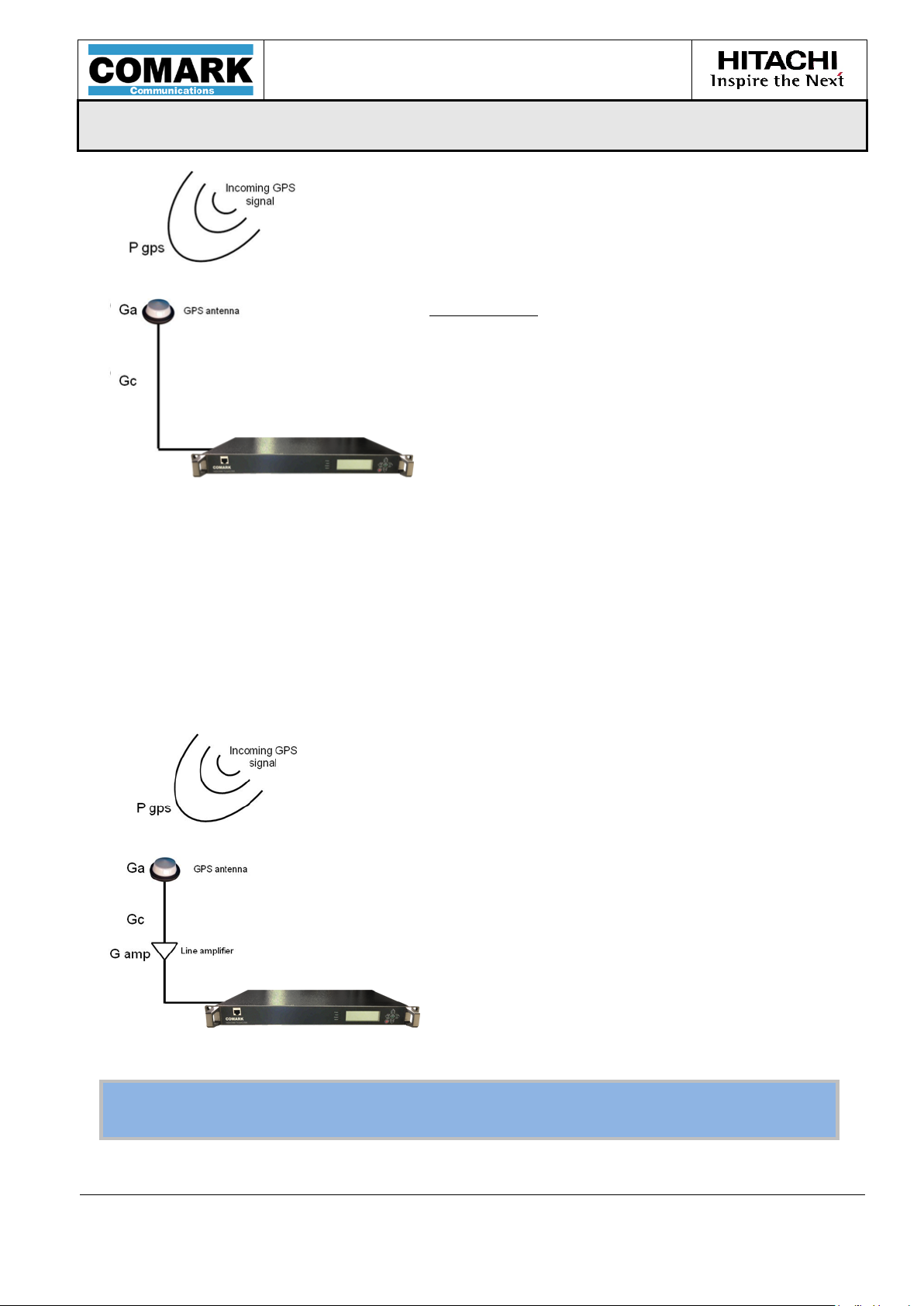
USER MANUAL
MPD-1611291-A
EXACT-V2 High End Rack Modulator / Exciter
3/10/2017
Page 89/94
Warning: For the GPS reception to be optimal, it is highly recommended to place
the Antenna in an open, free space (top of the building, etc.)
While doing GPS installation and setup for a
product with an embedded GPS receiver, it is
highly recommended to respect the following
conditions:
Considering:
Pgps as the power of the incoming signal
(nominal value over the covered area)
Ga as the gain of the dedicated GPS antenna
Gc as the losses of the several RF components
(cable, connectors,…)
Gt as the total Gain of the RF chain
Gt = Ga + Gc
The user shall respect the following condition:
20 dB ≤ Gt ≤ 35 dB
In order to fulfill this condition, and if Gt is not sufficient, the user can also add a line
Amplifier, as shown in the drawing below:
with Gt = Ga + Gc + Gamp
MPD-1611291-A
Page 90

USER MANUAL
MPD-1611291-A
EXACT-V2 High End Rack Modulator / Exciter
3/10/2017
Page 90/94
MPD-1611291-A
Page 91

USER MANUAL
MPD-1611291-A
EXACT-V2 High End Rack Modulator / Exciter
3/10/2017
Page 91/94
Appendix
B Example of GPS Antenna
MPD-1611291-A
Page 92

USER MANUAL
MPD-1611291-A
EXACT-V2 High End Rack Modulator / Exciter
3/10/2017
Page 92/94
MPD-1611291-A
Page 93

USER MANUAL
MPD-1611291-A
EXACT-V2 High End Rack Modulator / Exciter
3/10/2017
Page 93/94
MPD-1611291-A
Page 94
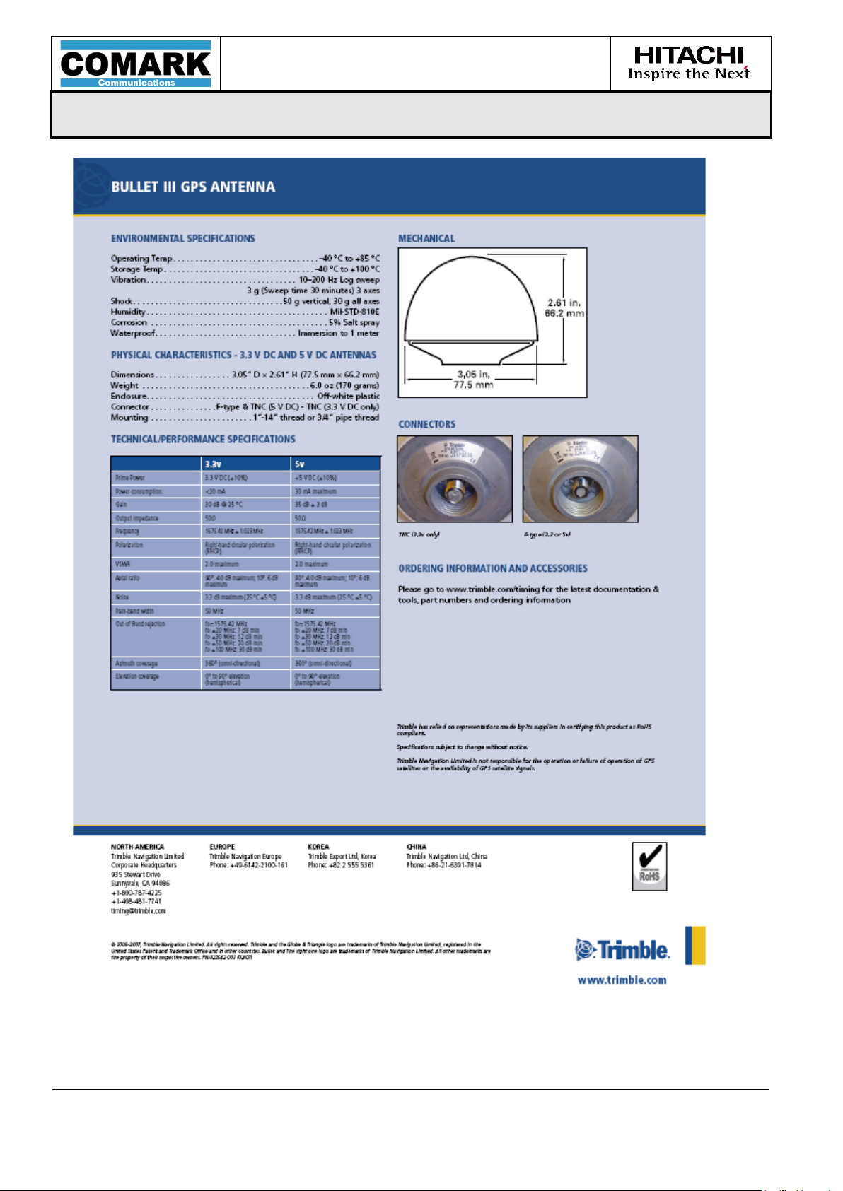
USER MANUAL
MPD-1611291-A
EXACT-V2 High End Rack Modulator / Exciter
3/10/2017
Page 94/94
MPD-1611291-A
 Loading...