

Page 1

®
DataMan
8072 ER
Reference Manual
2019 October08
Revision: 6.1.6SR1.5
Page 2

Legal Notices
Legal Notices
The software described in this document is furnished under license, and may be used or copied only in accordance with
the terms of such license and with the inclusion of the copyright notice shown on this page. Neither the software, this
document, nor any copies thereof may be provided to, or otherwise made available to, anyone other than the licensee.
Title to, and ownership of, this software remains with Cognex Corporation or its licensor. Cognex Corporation assumes
no responsibility for the use or reliability of its software on equipment that is not supplied by Cognex Corporation.
Cognex Corporation makes no warranties, either express or implied, regarding the described software, its
merchantability, non-infringement or its fitness for any particular purpose.
The information in this document is subject to change without notice and should not be construed as a commitment by
Cognex Corporation. Cognex Corporation is not responsible for any errors that may be present in either this document or
the associated software.
Companies, names, and data used in examples herein are fictitious unless otherwise noted. No part of this document
may be reproduced or transmitted in any form or by any means, electronic or mechanical, for any purpose, nor
transferred to any other media or language without the written permission of Cognex Corporation.
Copyright © 2019. Cognex Corporation. All Rights Reserved.
Portions of the hardware and software provided by Cognex may be covered by one or more U.S. and foreign patents, as
well as pending U.S. and foreign patents listed on the Cognex web site at: cognex.com/patents.
The following are registered trademarks of Cognex Corporation:
Cognex, 2DMAX, Advantage, AlignPlus, Assemblyplus, CheckitwithChecker, Checker, CognexVisionforIndustry,
CognexVSOC, CVL, DataMan, DisplayInspect, DVT, EasyBuilder, Hotbars, IDMax, In-Sight, LaserKiller, MVS-8000,
OmniView, PatFind, PatFlex, PatInspect, PatMax, PatQuick, SensorView, SmartView, SmartAdvisor, SmartLearn,
UltraLight, VisionSolutions, VisionPro, VisionView
The following are trademarks of Cognex Corporation:
The Cognex logo, 1DMax, 3D-Locate, 3DMax, BGAII, CheckPoint, CognexVSoC, CVC-1000, FFD, iLearn, In-Sight
(design insignia with cross-hairs), In-Sight2000, InspectEdge, Inspection Designer, MVS, NotchMax, OCRMax,
PatMaxRedLine, ProofRead, SmartSync, ProfilePlus, SmartDisplay, SmartSystem, SMD4, VisiFlex, Xpand
Portions copyright © Microsoft Corporation. All rights reserved.
Portions copyright © MadCap Software, Inc. All rights reserved.
Other product and company trademarks identified herein are the trademarks of their respective owners.
2
Page 3

Table of Contents
Table of Contents
Legal Notices 2
Table of Contents 3
Symbols 4
Getting Started 5
About DataMan 8072 ER 5
DataMan 8072 ER Accessories 6
DataMan 8072 ER Other Accessories 6
DataMan 8072 ER Reader Cables 7
DataMan 8000 Series Base Station Cables 7
Physical Layout of the Base Station 8
Setting Up Your DataMan 8072 ER 9
Setting Up the Reader 9
Install the DataMan SetupTool 9
DataMan 8072 ER Specifications 10
DataMan 8072 ER Imager Specifications 10
DataMan Base Station Specifications 10
LED Wavelengths 11
Connection Options 12
Connecting a DataMan 8072 ER Through Ethernet 12
Troubleshootingan Ethernet Connection 13
Connecting a DataMan 8072 ER Through RS-232 13
Connecting a DataMan 8072 ER Through USB 15
Using DataMan 8072 ER Wireless Reader 16
Connecting to a Wireless DataMan8072 ER Through a Base Station 16
Pairing Strategy (DMA-IBASE-BT-02) 18
Base Station Routing Capabilities 20
Wireless Reader: Buffering Data 20
Summary of Wireless Buffering Indicators 22
Wireless Reader: Charging 22
Reading Codes with the DataMan 8072 ER 25
Industrial Protocols 25
Trigger Types 26
Field of View and ReadingDistances 26
Cleaning and Maintenance 27
Cleaning the Reader Housing 27
Cleaning the Reader Lens Cover 27
Compliance Information, Warnings and Notices 28
Regulations/Conformity 28
Compliance Statements: DataMan Base Station 29
中 国 大 陆 RoHS (Information for China RoHS Compliance) 30
Precautions 32
3
Page 4
Symbols
The following symbols indicate safety precautions and supplemental information:
WARNING: This symbol indicates a hazard that could cause death, serious personal injury or electrical shock.
CAUTION: This symbol indicates a hazard that could result in property damage.
Note: This symbol indicates additional information about a subject.
Tip: This symbol indicates suggestions and shortcuts that might not otherwise be apparent.
Symbols
4
Page 5
Getting Started
Getting Started
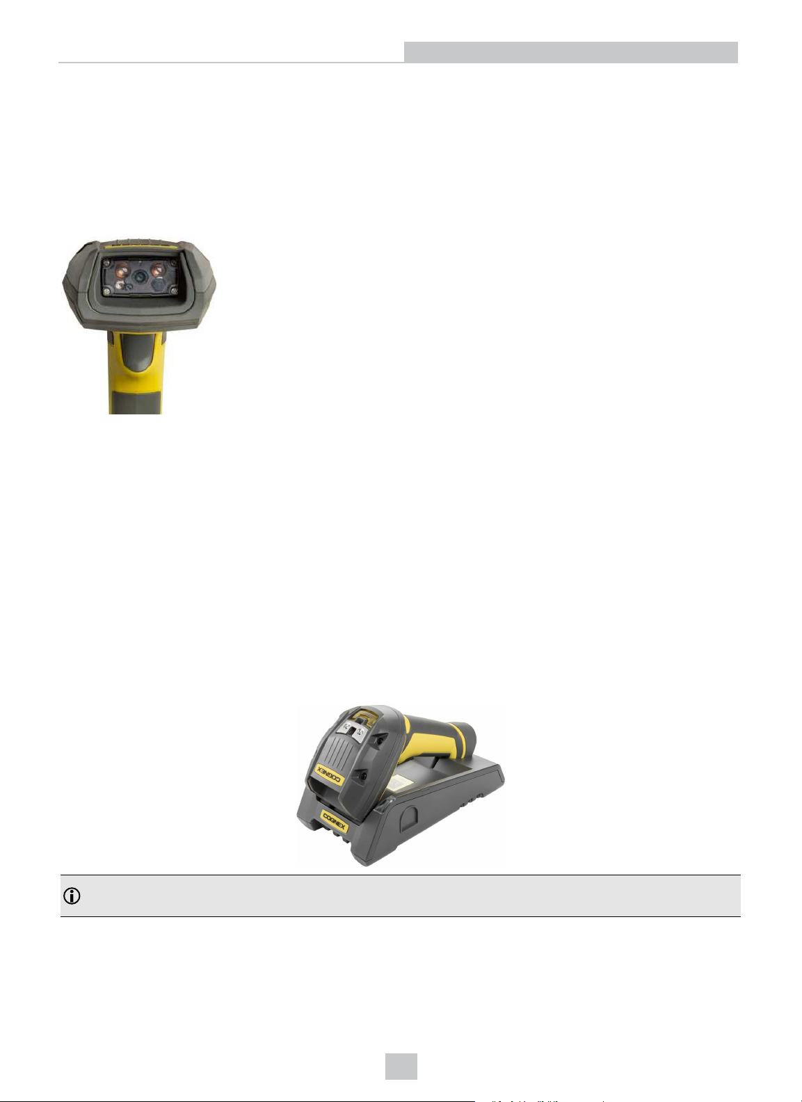
This section provides general information about the DataMan 8072 ER readers and the DataMan 8000 series base
stations. You can also find information on the DataMan 8072 ER accessories and the physical layout of the reader and
the base stations in this section.
About DataMan 8072 ER
The DataMan 8072 ER readers offer the industry’s most advanced technology for reading 1D and 2D codes regardless
of size, quality, printing method or surface, and belong to the only industrial handheld ID reader family that offers
Industrial Ethernet communication. DataMan 8072 ER is available with patented 1DMax+ with Hotbars, class-leading 2D algorithms and future-proof modular communication slide-ins.
The DataMan 8072 ER readers are available with the following communication options:
l Ethernet
l USB
l RS-232
l Bluetooth
An intelligent base station is also provided when the DataMan 8072 ER reader uses the wireless (Bluetooth)
communication module. The base station acts as a router between the reader and your computer or network.
Note: Henceforward, the term ‘wireless’ refers in this document to the Bluetooth communication module of the
reader.
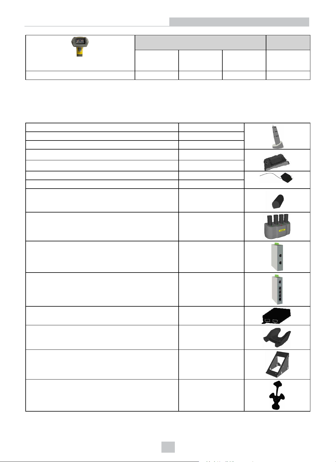
The DataMan 8000 series base stations are available with the following communication options:
5
Page 6
Getting Started
Base Station Communication Wireless
Protocol
Ethernet with
Industrial
Protocols
DMA-IBASE-BT-02 √ √ √ √
USB RS-232 Bluetooth
DataMan 8072 ER Accessories
DataMan 8072 ER Other Accessories
Serial/USB slide-in
Ethernet slide-in DMCM-ENETM-00
Bluetooth slide-in DMCM-BTM-00
Charging Base Station
Intelligent Bluetooth Base Station DMA-IBASE-BT-02
Power Supply for base station DMA-24VPWR-xx*
Power Supply for reader DM100-PWR-000
Battery for the wireless reader
Multi-Battery Charger DMA-MBC-xx*
POE Adapter CPS-24V-POE1
POE Adapter CPS-24V-POE4
DMCM-SERIALM-00
DMA-CBASE-01
DMA-HHBATTERY-02
POE Adapter CPS-AC-POE1A-xx*
Wall Mount DMA-WALL-8000-00
Wall Mount for Base Station DMA-IBASE-WALL-00
Stand DM-STAND-00
6
Page 7
*XX can be US, EN, UK, or JP
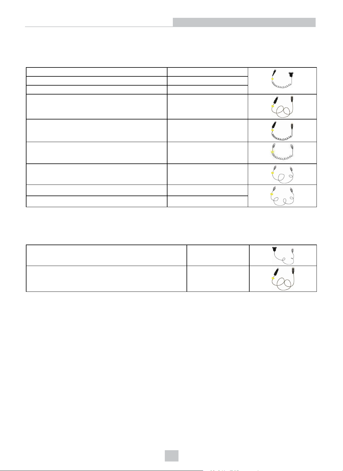
DataMan 8072 ER Reader Cables
RS-232 coiled cable for reader, 2.5 m DM8000-RS232-02
RS-232 industrial cable for reader, 2.5 m DM8000-RS232IND-02
RS-232 coiled cable for reader, 4 m DM8000-RS232-05
USB cable, 2.5 m DM8500-USB-00
USB coiled cable, 2.5 m DM8500-USBC-02
Ethernet Coiled cable, 5m DM8000-ECABLEC-05*
Ethernet cable, 2.5 m DM8000-ECABLE-02
Ethernet cable, 5 m DM8000-ECABLE-05
Getting Started
Ethernet cable, 30 m DM8000-ECABLE-30
*Collimated cable length including DM8000-ECABLE-X should not exceed 50 m.
DataMan 8000 Series Base Station Cables
RJ25 (RJ12) to DSUB9 cable for base station, 5 m DMA-RS232RJ-05
Straight 10ft USB cable DMA-USB-00
l USB cable for base station: Use any standard USB-A to USB-B 2.0 cable up to 3 meters.
l Ethernet cable for base station: Use any standard CAT5/5e, SF/FTP or S/FTP cable.
7
Page 8
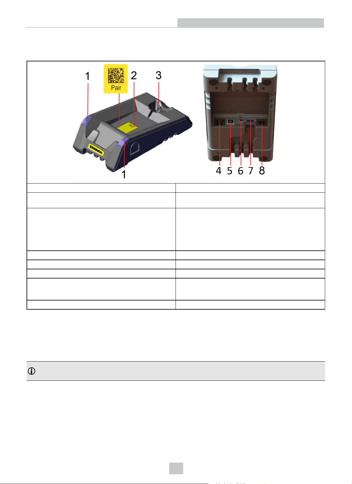
Physical Layout of the Base Station
DMA-IBASE-BT-02
1 Base station status indicators
2 PAIR sticker - Reading the code pairs the base station with
the device
3
Connection point to the reader:
Getting Started
l pairing reader and base station
l non-wireless communication
l charging
4 RS-232
5 USB
6 Power plug (24V, max. 15W)
7 Alternative power supply connector (24V, max. 15W,
polarity marked on the plastic part near the connector).
Recommended wire diameter is 14- 18 AWG
8 Ethernet
Base station status indicators:
l Power: RED = base powered / BLINK = wrong reader in base
l Communication: BLUE = Wireless link / BLINK = Wireless communication
l Cradle connections: GREEN = reader properly inserted / BLINK = cradle USB interface communication
Note:
l DMA-IBASE-BT-02 supports Ethernet
8
Page 9
Setting Up Your DataMan 8072 ER
Setting Up Your DataMan 8072 ER
This section provides information on how to set up and start working with your DataMan 8072 ER reader. It also
describes how to install the DataMan Setup Tool and at the end of the section, you will find the DataMan 8072 ER and
DataMan 8000 series base station specifications.
Setting Up the Reader
To be able to connect to your reader on your computer, you must perform the following steps:
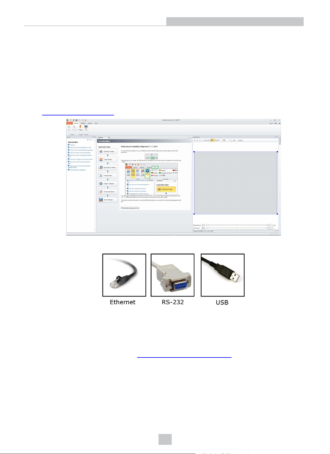
1. Install the DataMan Setup Tool on your computer.
2. Select the connection type: Ethernet, RS-232 Serial, or USB; and connect the appropriate cabling.
3. Power on your device(s).
Install the DataMan SetupTool
1. Check the DataMan Release Notes for a full list of system requirements.
2. Download the DataMan Setup Tool from http://www.cognex.com/support/dataman and follow the on-screen
steps.
3. Connect the DataMan 8072 ER to your PC.
4. Launch the DataMan Setup Tool and click Refresh. The reader or the base station appears under COM ports or
Network devices.
9
Page 10
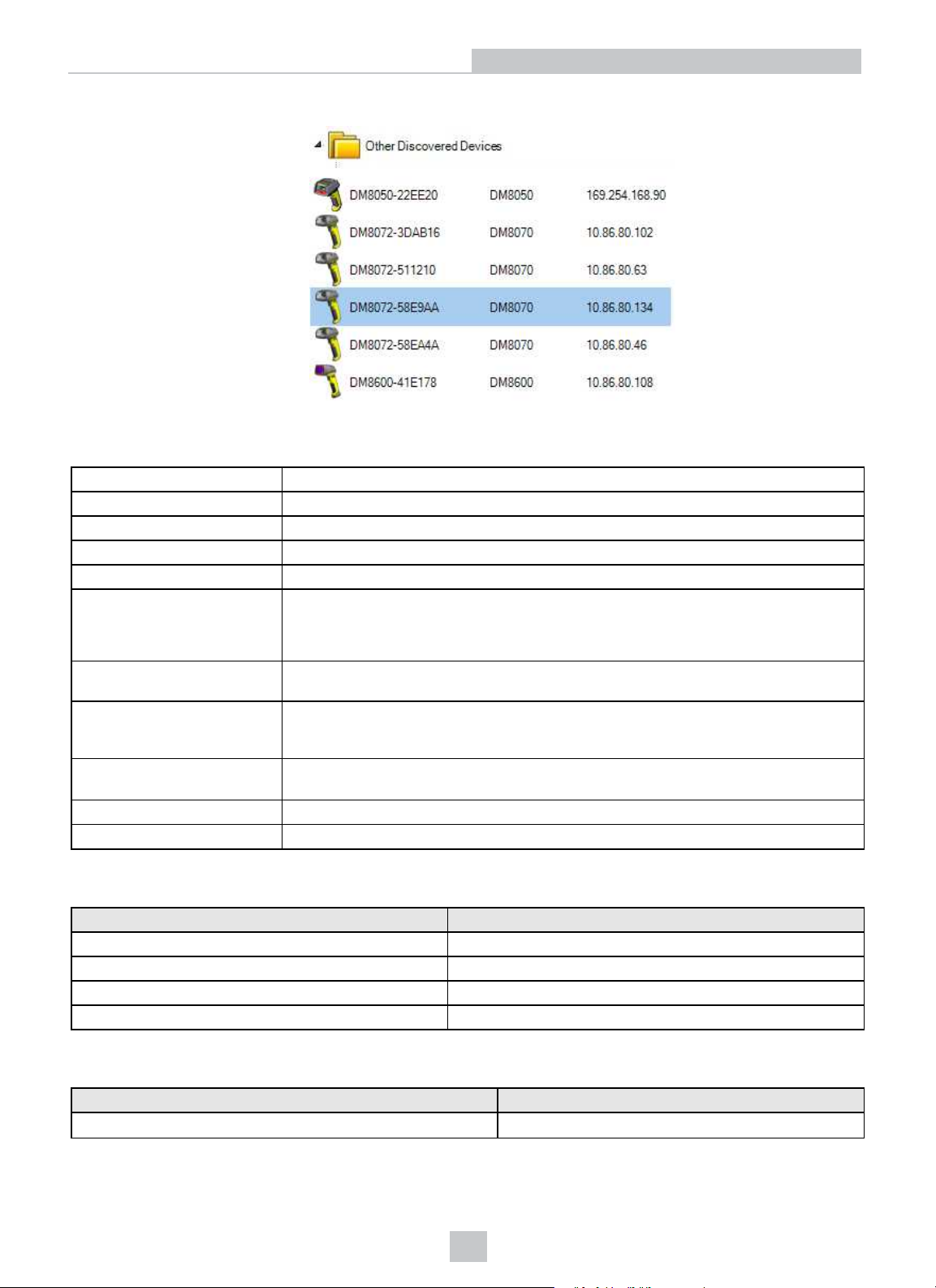
5. Select a COM port or a Network device and click Connect.
DataMan 8072 ER Specifications
Setting Up Your DataMan 8072 ER
Weight
Operating Temperature
Storage Temperature
Maximum Humidity < 95% (non-condensing)
Environemntal IP65
Codes
Power Supply Requirements
Inrush current peak
Battery life for wireless reader
(typical use case)
Ethernet 10/100 Base-T FULL/HALF DUPLEX, IEEE 802.3
Bluetooth Bluetooth™ 2.1, 2.4 GHz
254g
0ºC — 40ºC (32ºF — 104ºF)
-10ºC — 60ºC (14ºF — 140ºF)
1-D barcodes: Codabar, Code 39, Code 128, and Code 93, Interleaved 2 of 5,
Pharma, GS1 DataBar, Postal, UPC/EAN/JAN, DataBar
2-D barcodes: Data MatrixTM; QR Code and microQR Code, RSS/CS, PDF 417,
MicroPDF 417, MaxiCode, Aztec Code
USB: external 5.0 W maximum LPS or NEC class 2 power supply: +5V - +6V DC
RS232 external 5.0W max LPS or NEC class 2 power supply
5A maximum
Duration: approx. 30μs
Electrical charge: 60μAs at 6V
ca. 4100 triggers can be operated within a 13 hour working shift
DataMan 8072 ER Imager Specifications
Specification DataMan 8072 ER Imager
Image Sensor
Image Sensor Properties
Image Resolution (Pixels)
Lens Type 12 mm F:7 lens with liquid lens
1/3 inch CMOS
3.75 μm square pixels
1280 x 960
DataMan Base Station Specifications
DMA-IBASE-BT-02
Weight 300 g
10
Page 11
Setting Up Your DataMan 8072 ER
DMA-IBASE-BT-02
Operating Temperature 0ºC — 45ºC (32ºF — 113ºF)
Storage Temperature -40ºC — 60ºC (-40ºF — 140ºF)
Maximum Humidity 95% (non-condensing)
Power Supply Requirements
24V +-10%, 15 W maximum LPS or NEC class 2
power supply
Recommended wire diameter is 14-18 AWG
LED Wavelengths
The following table shows LED types and the related wavelengths:
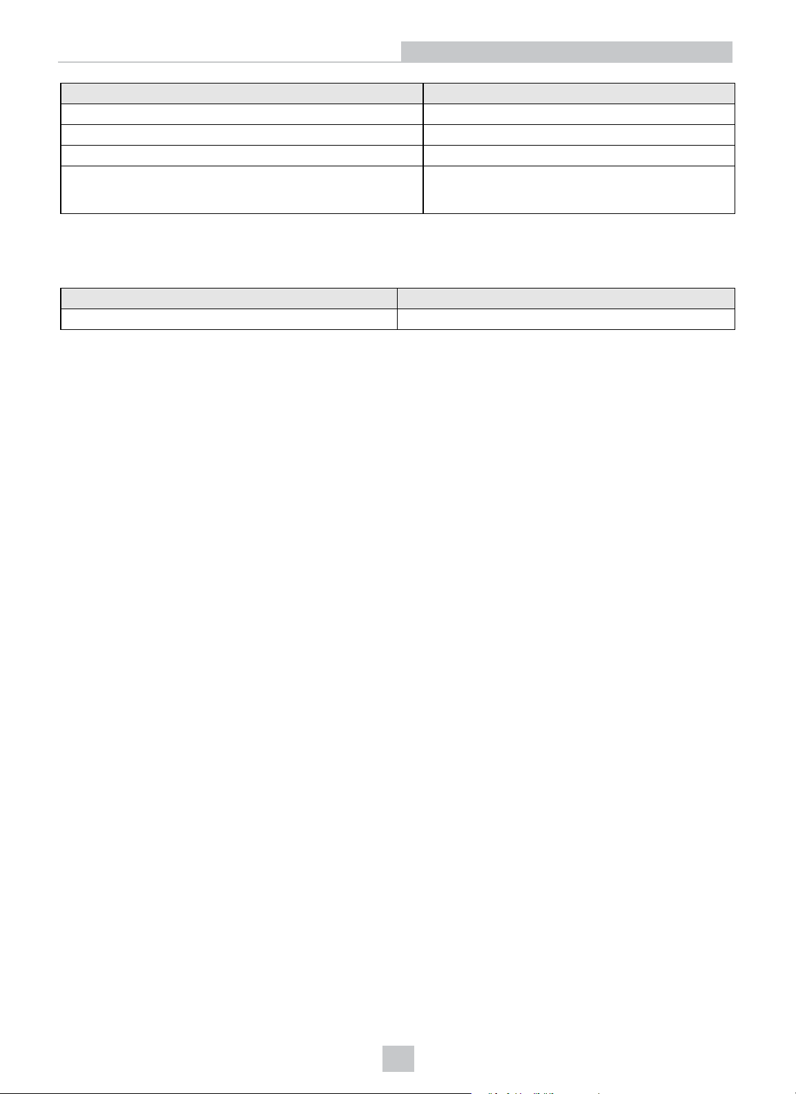
LED λ [nm]
RED
623
11
Page 12
Connection Options
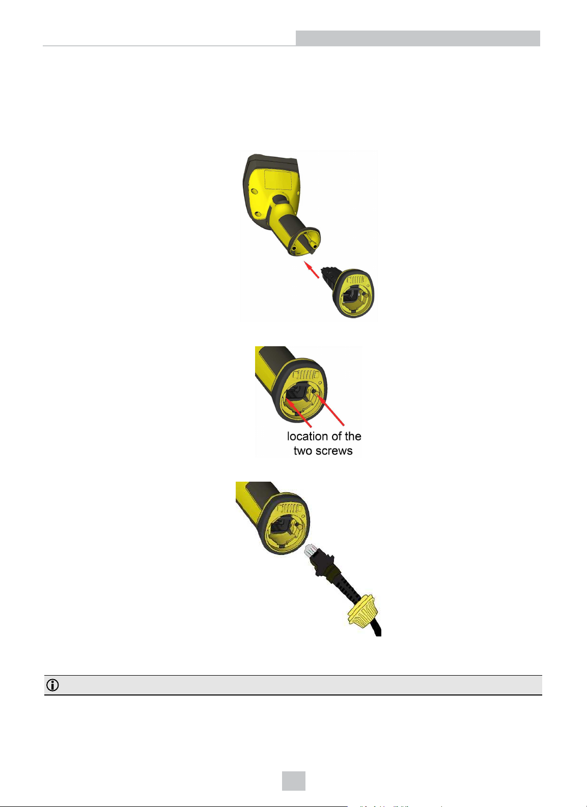
Connecting a DataMan 8072 ER Through Ethernet
1. Connect the Ethernet slide-in (DMCM-ENETM-00) to your DataMan 8072 ER.
Connection Options
2. With a 2.5 mm Allen wrench, tighten the screws so that the slide-in is firmly locked.
3. Insert the plug and slide the cable lock up to the reader, and twist the cable lock in place.
Use the DM8000-ECABLE-05 (5 meters) or the DM8000-ECABLE-30 (30 meters). You also need a Power Over Ethernet
Adapter (CPS-AC-POE1A-xx).
Note: Disconnect the DataMan 8072 ER reader from power before inserting/removing communication modules.
12
Page 13
Connection Options
Troubleshooting an Ethernet Connection
If your reader does not appear in the DataMan Setup Tool’s list of detected network devices, you may need to adjust your
network settings.
1. First, check your Ethernet connection and click Refresh in the DataMan Setup Tool.
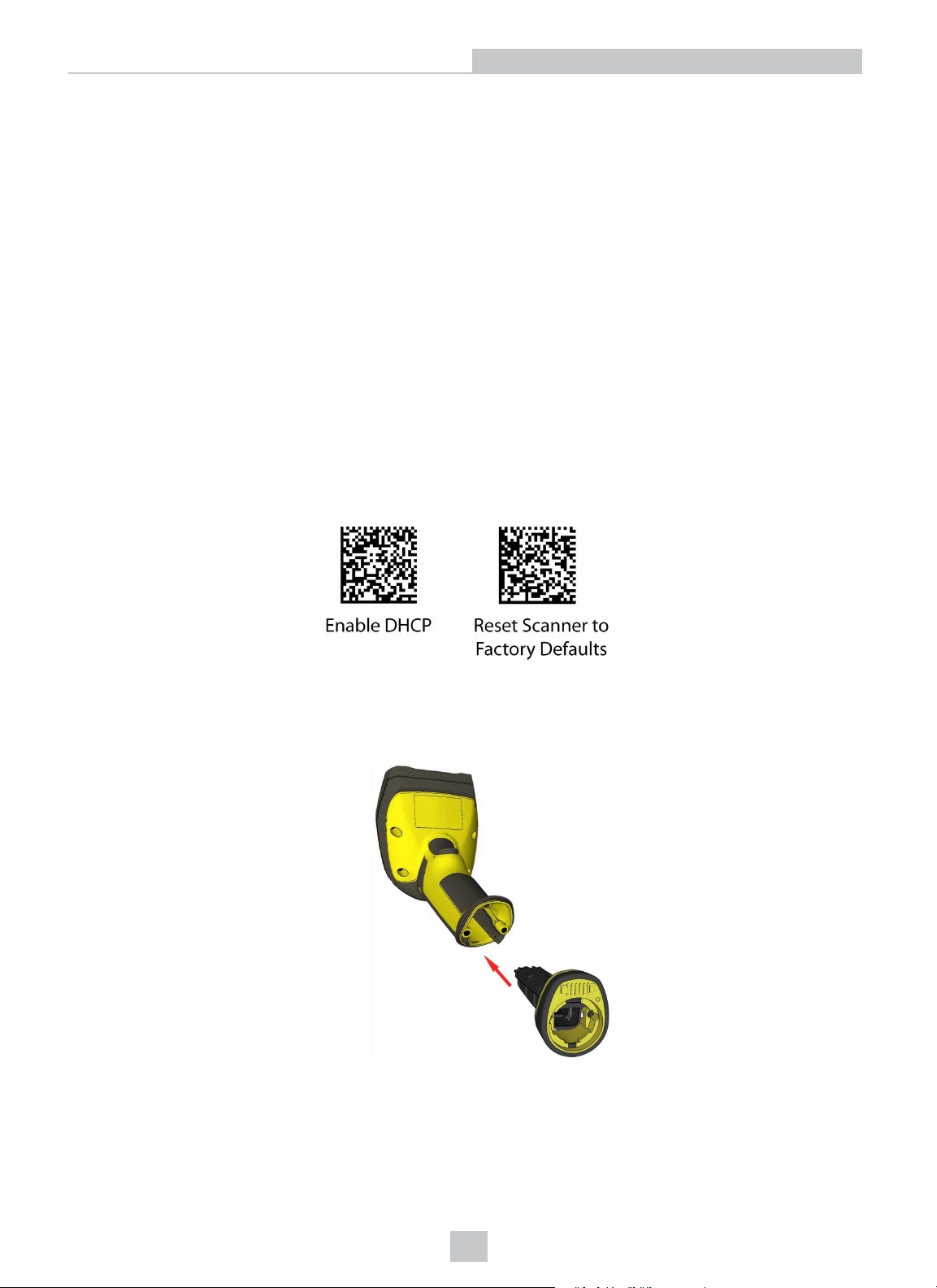
2. Next, scan the Enable DHCP code below (which you can also find in the DataMan Reader Configuration Codes
document available from the Windows Start menu or the Setup Tool Help menu). This might allow the reader to
acquire a suitable IP address from a DHCP server on your subnet.
If the reader still does not appear, you can use either the Add Device or Force Network Settings options in the DataMan
Setup Tool.
1. If you know the IP address of the reader, use the Add Network Device option under Reader Maintenance.
2. If you do not know the IP address, use the Force Network Settings option. Either method should allow the
DataMan 8072 ER reader to appear in the list of Network devices so that you can connect to it through the
DataMan Setup Tool and your Ethernet connection.
If none of the above helps, reset your reader to factory defaults by scanning the Reset Scanner to Factory Defaults
code below.
Connecting a DataMan 8072 ER Through RS-232
1. Connect the serial slide-in (DMCM-SERIALM-00) to your DataMan 8072 ER.
13
Page 14
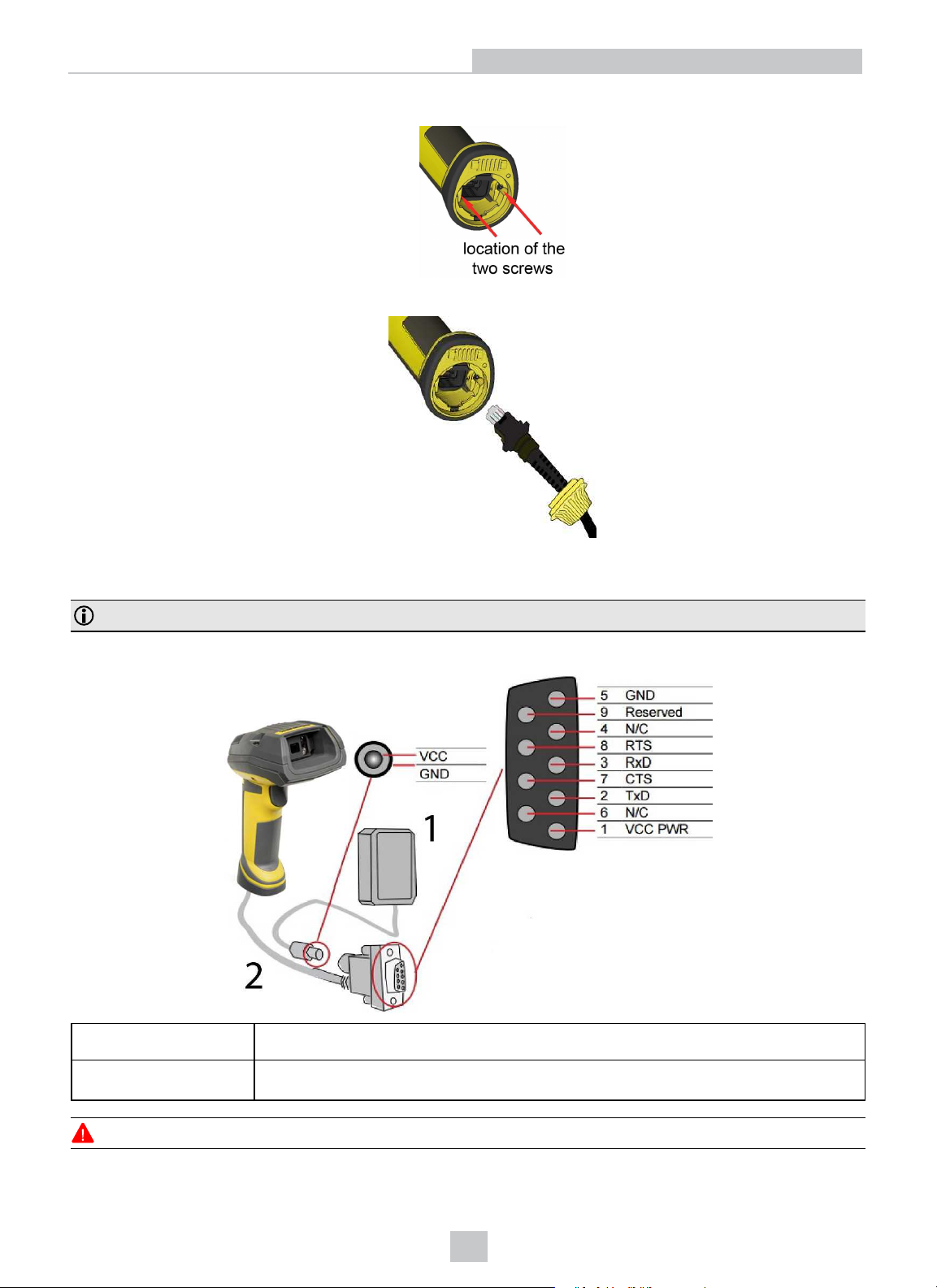
2. With a 2.5 mm Allen wrench, tighten the screws so that the slide-in is firmly locked.
3. Insert the plug and slide the cable lock up to the reader and twist the cable lock in place.
Connection Options
Use the DM8000-RS232-02 cable (2.5 meters) or the DM8000-RS232-05 cable (5 meters). For power supply, use the
DataMan 8000 Power Supply (DM100-PWR-000).
Note: Disconnect the DataMan 8072 ER reader from power before inserting/removing the communication modules.
Observe the following electrical requirements:
1 6VDC power supply (DM100-PWR-000), a 5.5 mm x 2.1 mm DC Power Plug
2
WARNING: For proper RS-232 operation, do not apply any voltage to pin 9.
VCC = +4.75V up to +6.0V for 2.5 m cable
VCC = +5.5V up to +6.0V for 5.0 m cable
14
Page 15
Connection Options
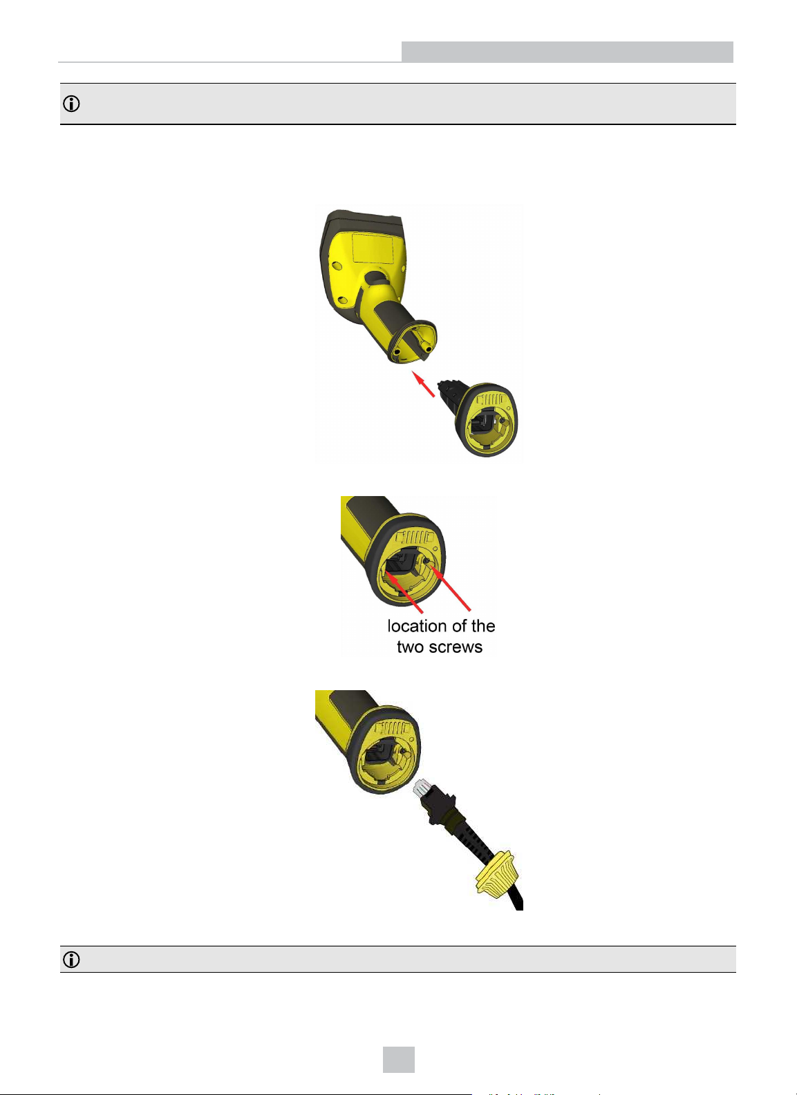
Note: Power on the RS-232 cable can be supplied by either the DC Power Plug or Pin 1 of the D-SUB. DO NOT use
both in parallel.
Connecting a DataMan 8072 ER Through USB
1. Connect the serial slide-in (DMCM-SERIALM-00) to your DataMan 8072 ER.
2. With a 2.5 mm Allen wrench, tighten the screws so that the slide-in is firmly locked.
3. Insert the plug, slide the cable lock up to the reader and twist the cable lock in place.
Use the DM8500-USB-00 cable (2.5 meters) or the DM8500-USBC-02 cable (2.5 meters).
Note: Disconnect the DataMan 8072 ER reader from power before inserting/removing the communication modules.
15
Page 16
Connection Options
Using DataMan 8072 ER Wireless Reader
Connecting to a Wireless DataMan 8072 ER Through a Base Station
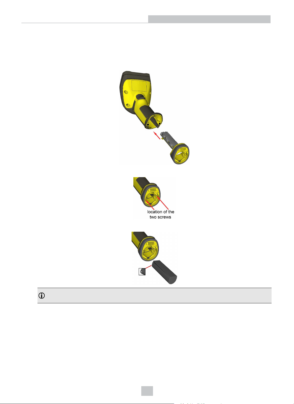
1. Connect the wireless slide-in (DMCM-BTM-00) to your DataMan 8072 ER.
2. With a 2.5 mm Allen wrench, tighten the screws so that the slide-in is firmly locked.
3. Insert the battery.
Note: Remove the battery from your DataMan 8072 ER before inserting/removing the communication
module.
16
Page 17
Connection Options
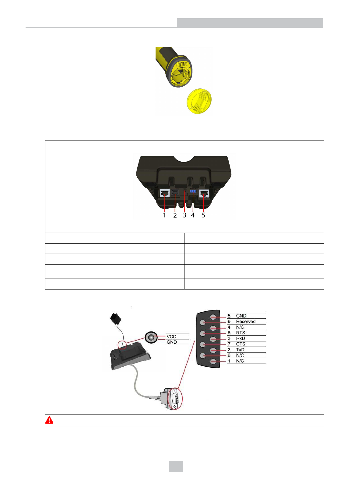
4. Insert the plug and twist it in place.
5. Power up the DMA-IBASE-BT-XX base station using a 24V power supply (DMA-24VPWR-XX).
6. Connect your base station to your PC using either serial, USB or Ethernet communication.
DMA-IBASE-BT-02
1 RS-232 connection (RJ-25 port)
2 USB Type B connection
3 Power (24 V, max 15W)
4
5 Ethernet connection
Observe the following electrical requirements when connecting the base station through RS-232:
Alternative power supply connector (24V, max 15W,
polarity marked on plastic part near connector)
WARNING: For proper RS-232 operation, do not apply any voltage to pin 9.
17
Page 18
Connection Options
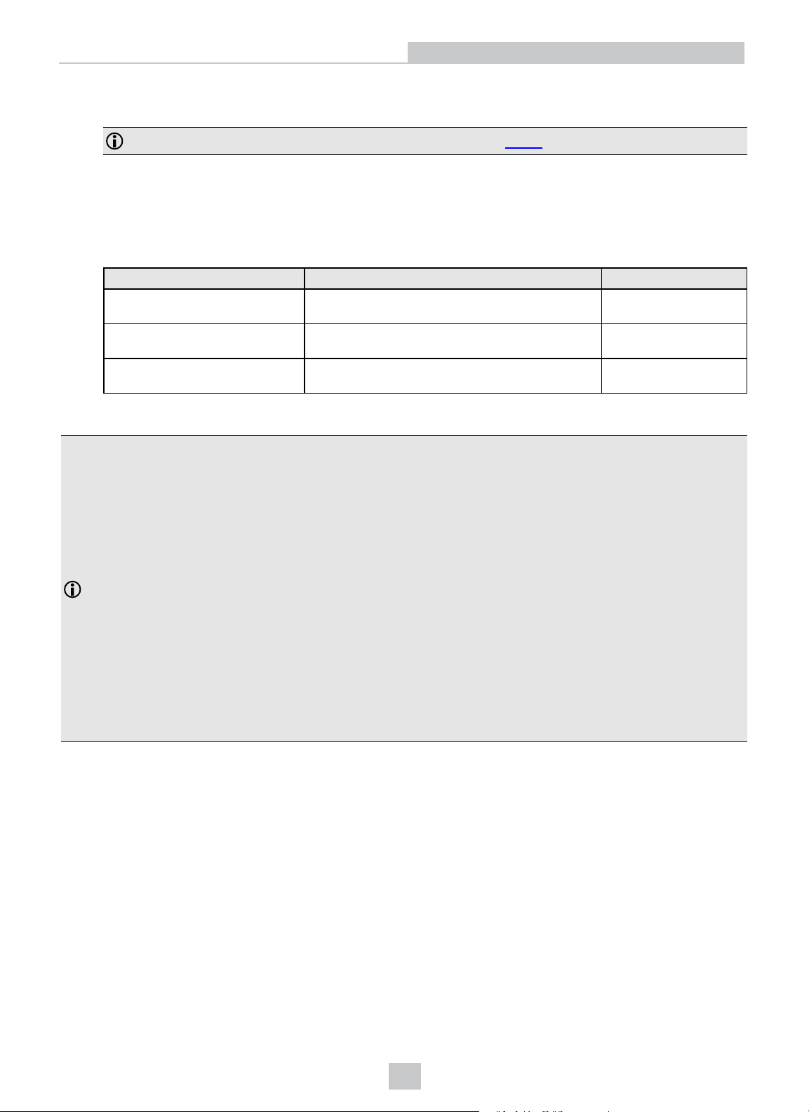
Power to the base station can be supplied by either the DC power plug or by wiring in 24V. DO NOT use both in
parallel. The DC power plug is a 24VDC power supply (DMA-24VPWR-xx), 3.5 mm x 1.3 mm.
Note: Be careful to use the appropriate connector for RS-232. See Step 6 above.
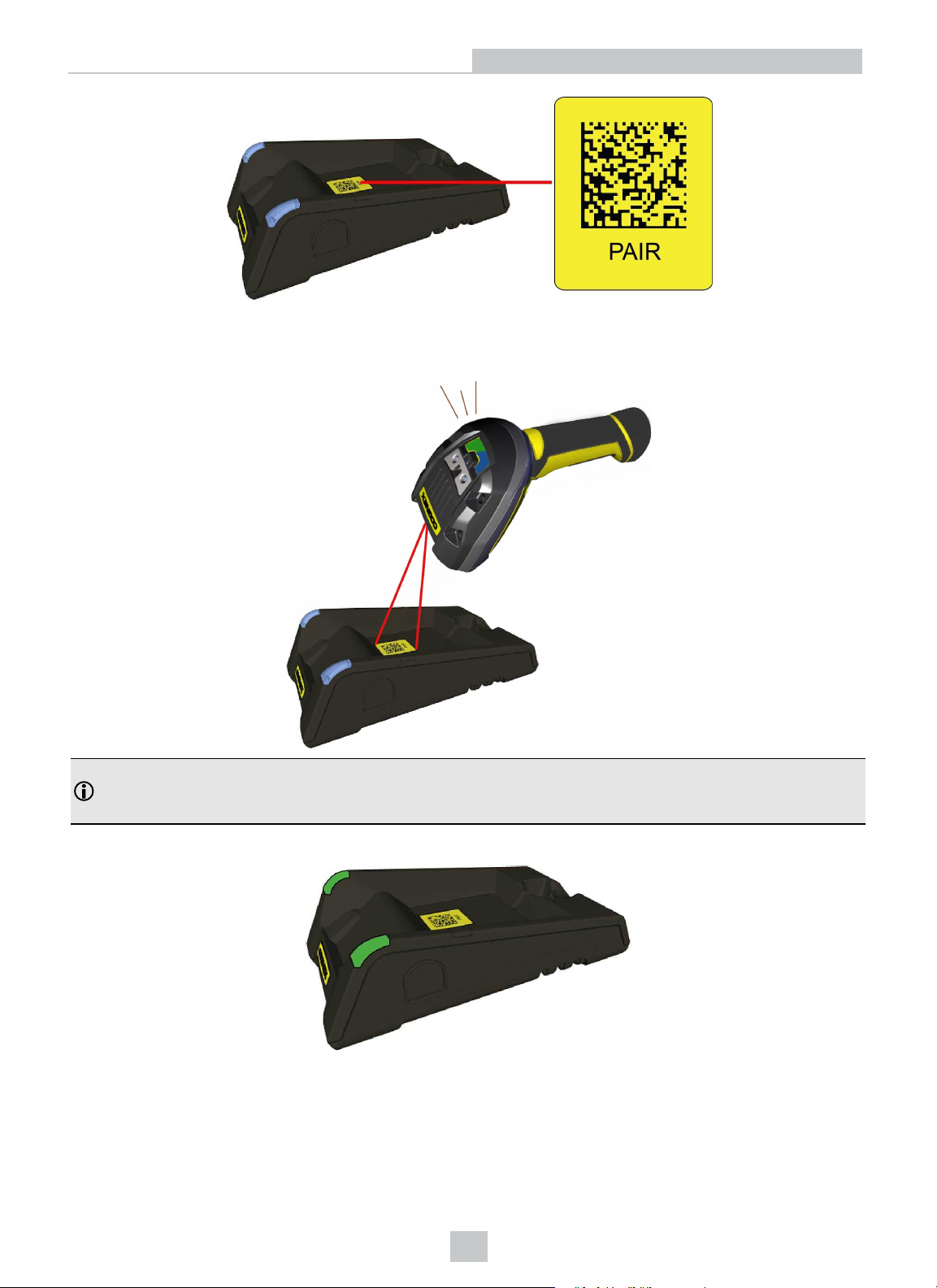
7. When the base station is powered up, scan the Pair scan code and place your reader into the base station. The
base station’s status indicator becomes green. When the wireless reader is removed from the base, a wireless
connection is established. The status indicator of both the base station and the reader become blue and you can
hear a beep. Blue lights indicate that the reader and the base have successfully paired and are communicating.
8. Connect to your base station or to the wireless reader. You have the following connection options:
Base Station Connection Type Connect to Reader in the DataMan Setup Tool Connection Channels
RS-232
Wireless reader appears: COM port
(Base Station does not appear)
USB
Base Station appears: COM port 1
Wireless reader appears: COM port 2
Ethernet
Base station appears: Network device 1
Wireless reader appears: Network device 2
9. Lift your reader up from the base station and start reading codes.
Note:
l When the reader is on the base station, communication is established by means of cradle contacts. Wireless
communication is disabled.
terminal program
Setup Tool
terminal program
Setup Tool
terminal program
Setup Tool
l Configure wireless communication settings by connecting to the base station. In order for the changed
settings to be synchronized between the DataMan 8072 ER wireless reader and the base station, place
your reader in the base station after your changes are saved. To assign a static IP address to the base
station or the reader when communicating via Ethernet, connect to the base station in the DataMan Setup
Tool. The base station, however, auto-assigns the IP address to the reader when they become paired.
l When you connect with the base station to a terminal program, your wireless reader sends decode results to
the terminal, but you cannot send commands to the reader.
l If you want to unpair your reader from the base station, you can either click Unassign in the Bluetooth or
Wireless tab of the Communication Settings pane of the DataMan Setup Tool (when you are connected
either with the reader or the base station), or scan the “Unassign Reader” reader configuration code.
l If you place the wrong reader (that is, a reader that is not associated with the base station) into the base
station, the base station status indicator flashes red and a series of short beeps can be heard.
Pairing Strategy (DMA-IBASE-BT-02)
In order to pair the base station and the reader in a single step without considering former pairing states and without
using the DataMan Setup Tool, scan the Pair sticker from the scan code sticker on the base station. Place the reader in
the base station.
18
Page 19
Connection Options
The reader then blinks green/blue until it gets paired with the base station (or until the end of the 20 second timeout
period). When the reader is put on the base station, the base station drops its pairing with its old reader and pairs with
the new reader.
Note: Scanning the Pair code puts the base station and the reader put on it into force pairing mode. This means
that the reader and the base it is put on get paired regardless of any assignments they both had previously. This
force pairing mode is valid for 20 seconds after reading the Pair code.
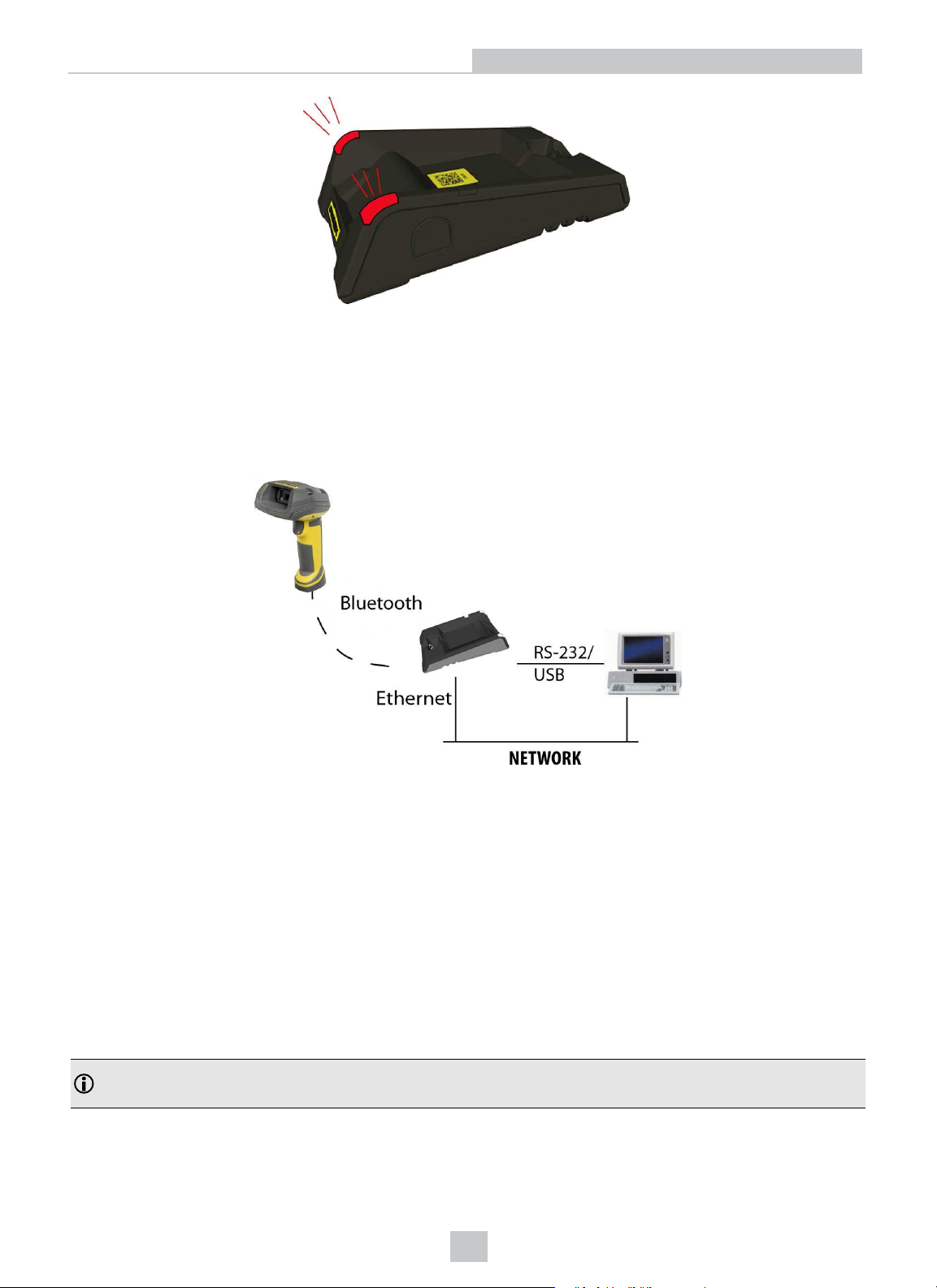
The base station’s indicators turn green to indicate successful pairing:
When the reader is put onto another (unpaired) base station without any previous actions, the base station signals this
event with beeping and red flashing of its indicators:
19
Page 20
Connection Options
The base station that is paired with a certain reader signals a bad reader alert (beeps and flashing red indicators) also
when another, unassigned reader is put into it.
Base Station Routing Capabilities
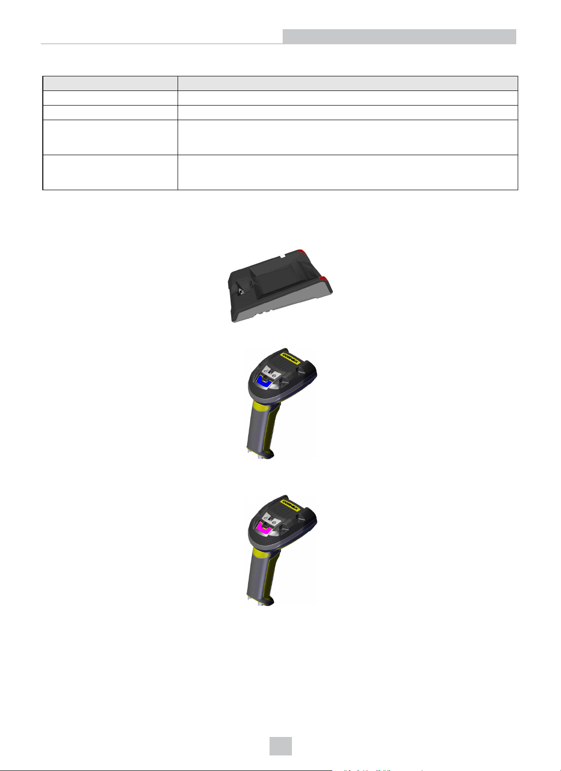
The base station is visible as connected through either RS-232, USB or Ethernet, but it routes data through the wireless
interface to the reader.
Wireless Reader: Buffering Data
When you are within the wireless range of the base station, your wireless reader sends decoded data to your PC through
the base station, just as if you used a tethered reader. You can also see the decoded images in the DataMan Setup Tool,
if it is running and is connected to the reader.
When you leave the wireless range, however, you lose connection to your PC, but you can still keep reading codes. The
decoded data is saved in the buffer of the reader.
This buffered data appears on your PC again when you come back within the wireless range, but ONLY IF you were
connected to a terminal program when you left the wireless range.
Buffered read results on the reader are not displayed in the DataMan Setup Tool; they are only transmitted over an
existing keyboard emulation, RS-232 Serial or TCP/IP Telnet connection.
Note: The images acquired by the reader when it is out of the wireless range are never saved, and cannot be
retrieved.
Open a connection with the reader in a terminal program so that you gain the buffered data when wireless connection is
established again.
20
Page 21
Connection Options
See the following table for connection options according to communication type:
Base Station Connection Type How to Connect
RS-232
USB Connect to the COM port of the wireless reader.
Ethernet Connect to the terminal program using the IP address of the reader. To find out the IP
address, go to the
USB Keyboard Open the text editor or your program of choice to use keyboard emulation. When you
return to the wireless range, keyboard emulation continues, starting with the buffered
While you are still within the wireless range, the reader occasionally blinks blue to indicate that the wireless connection
is established.
When the reader leaves the wireless range, the base station’s signal becomes red.
Connect to the COM port of the base station.
Connect
the IPaddress of the reader in the
backstage page in the DataMan Setup Tool and check
Address
data.
column.
Blinking blue status indicator: wireless connection is alive.
When you leave the wireless range, you can still keep reading codes. The reader going offline is indicated by a long
beep and the status indicator flashes magenta. The status indicator blinks magenta: your reader is offline.
When the reader is offline, good reads are indicated with 2 short beeps and the selected good read status indicator color
(green by default). The status indicator beeps twice: your reader is offline while decoding symbols.
21
Page 22
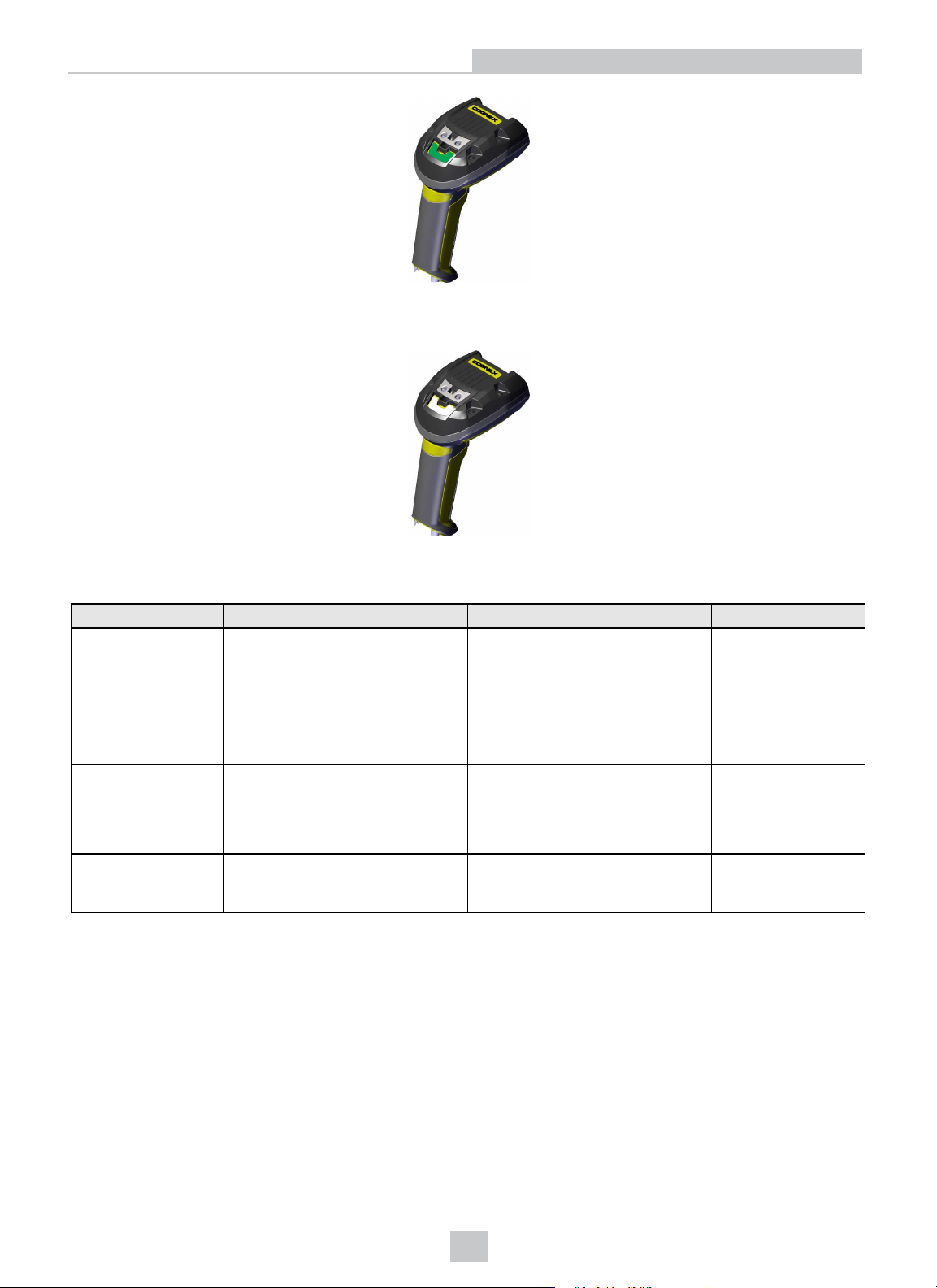
When the buffer is full, no more codes are read. The reader does not discard the oldest read.
When the buffer is full, the reader beeps and the status indicator becomes white.
Connection Options
Summary of Wireless Buffering Indicators
Condition Status Indicator: Reader Status Indicator: Base Station Sounds
Reader in wireless
range of base station
Reader out of
wireless range of
base station
Reader out of
wireless range, buffer
is full
When the ireader s awake, blinking
blue indicates wireless connection
with the base. When the reader is
offline, no indicator. Pull the trigger
to wake it up and it will blink blue.
Good read: green, single beep
(default)
No read: red, no beep (default)
Offline: When the reader wakes up
out of the wireless range, there is
no indicator.
Good read: green (default)
No read: red (default)
Good read:
No read:
red
green
and then white.
(default)
Reader out of the base station and
reader is awake: steady blue.
Reader out of the base station and
reader is offline: steady red. Paired
reader in the base station: flashing
green.
Base station is receiving data or
images from reader: steady blue.
Reader offline: steady
Reader offline: steady
red
red
.
.
Good read: 1 beep
(default)
No read: no beep
(default)
Long beep when you
leave the wireless
range.
Good read: 2 beeps
No read: no beep
Good read: long beep
No read: no beep
Wireless Reader: Charging
When you are reading codes with your wireless reader, blinking red status indicators will indicate a low battery. As the
battery discharges, the blink frequency increases. A blinking red status indicator indicates low battery or thermal
shutdown mode.
22
Page 23
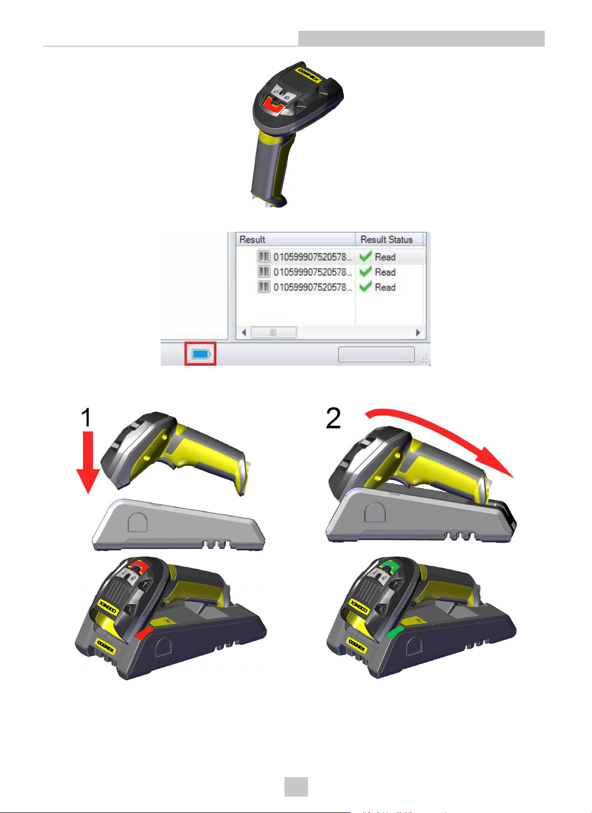
You can also check the status of the battery in the DataMan Setup Tool.
Connection Options
Place the reader on the base station for charging. Make sure that the pins at the end of the handle make contact with the
pins in the base station.
Paired Reader Charging Paired Reader Fully Charged
Refer to the following table for a summary of indicators regarding charging:
23
Page 24
Condition Status Indicator: Reader Status Indicator: Base Station
Battery low
Reader is charging in the base station steady
Reader is fully charged in the base station steady
flashing red
red
indicators
green
indicators
indicators
Connection Options
steady blue, indicating connection
flashing blue, indicating data transfer
steady green, indicating connection
flashing green, indicating data transfer
steady green, indicating connection
flashing green, indicating data transfer
24
Page 25
Reading Codes with the DataMan 8072 ER
Reading Codes with the DataMan 8072 ER
This section contains descriptions about trigger types as well as about the field of view and reading distances and the
industrial protocols supported by the DataMan 8072 ER reader.
Industrial Protocols
The DataMan 8072 ER readers support the following industrial protocols:
l EtherNet/IP™
l PROFINET
l SLMPProtocol
l Modbus TCP
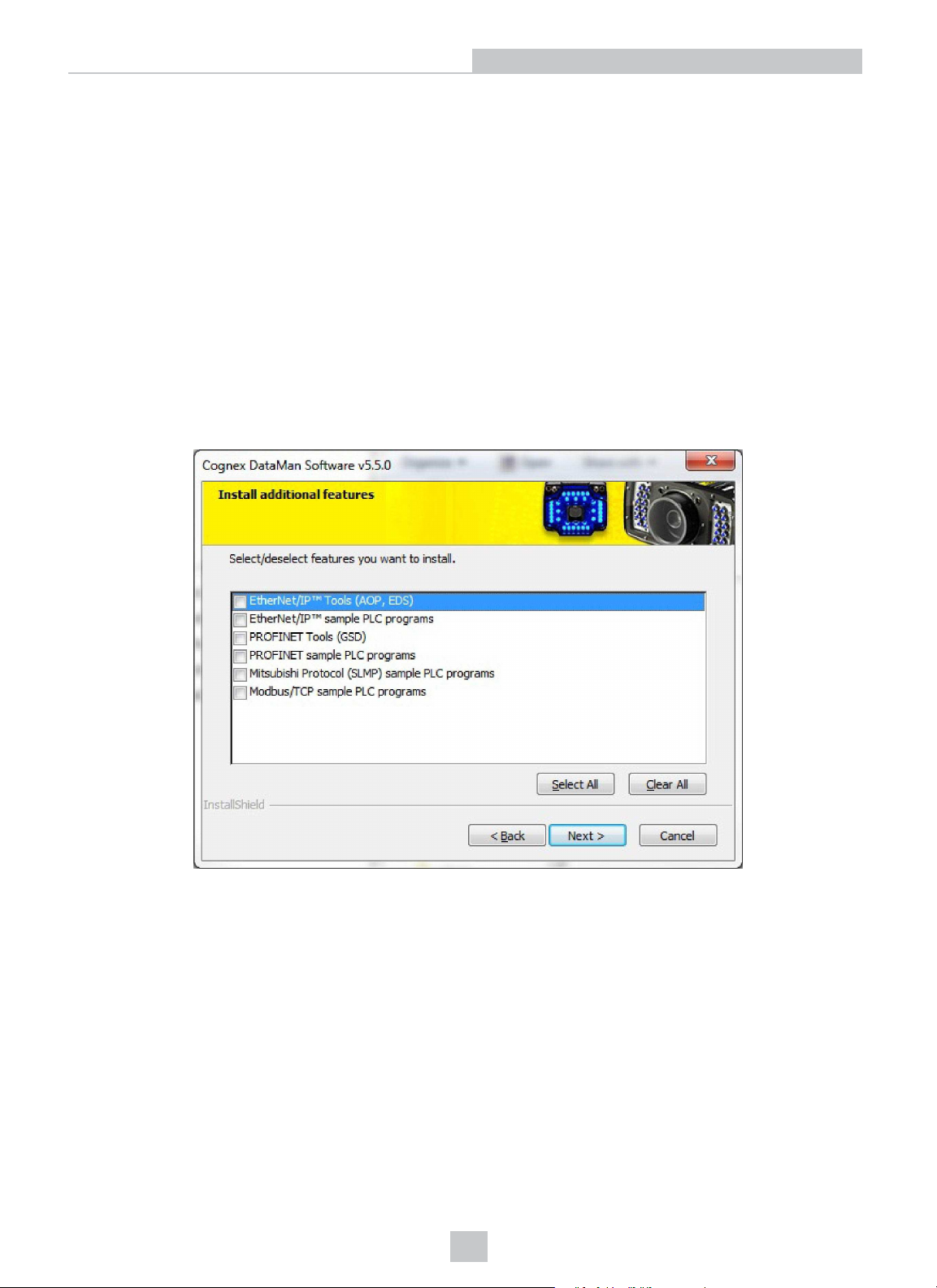
Select the industrial protocol tools and sample programs when installing the DataMan Setup Tool.
There are three ways to enable or disable Industrial Protocols. Using either method, a reboot is required for the changes
to come into effect.
l Enable the protocols using the Industrial Protocols pane of the DataMan Setup Tool (under Communication
Settings).
l Scan the appropriate Reader Configuration codes (see Reader Configuration Codes available through the
Windows Start menu or the Setup Tool Help menu).
l Send the appropriate DMCC (see Command Reference available through the Windows Start menu or the Setup
Tool Help menu).
For more information on using the industrial protocols, see the DataMan Industrial Protocols Manual available through
the Windows Start menu or the Setup Tool Help menu.
25
Page 26
Reading Codes with the DataMan 8072 ER
Trigger Types
The DataMan 8072 ER trigger mode determines when the reader attempts to read a code. Use the DataMan Setup Tool
or the appropriate reader configuration codes to change trigger types.
The following trigger types are supported:
l Presentation: The LED aimer is always on. When motion is detected in front of the reader, the reader will turn on
and scan for a symbol. The reader relies on an internal timing mechanism to acquire images.
l Manual (default): The reader begins acquiring images when you press the trigger button on the reader, and
continues acquiring images until a symbol is found and decoded or you release the button.
Note that while in Presentation mode, as the operator pulls the trigger, the reader switches to Manual mode until the
device is re-docked into the base station. Setup Tool continues to display Presentation mode while in this state. To bring
it back to standard Presentation mode, use one of the following options:
l Dock the device into the base station
l Switch to Manual trigger mode in Setup Tool, then switch back to Presentation mode
l Scan the Enter Presentation Reader Configuration Code
Field of View and Reading Distances
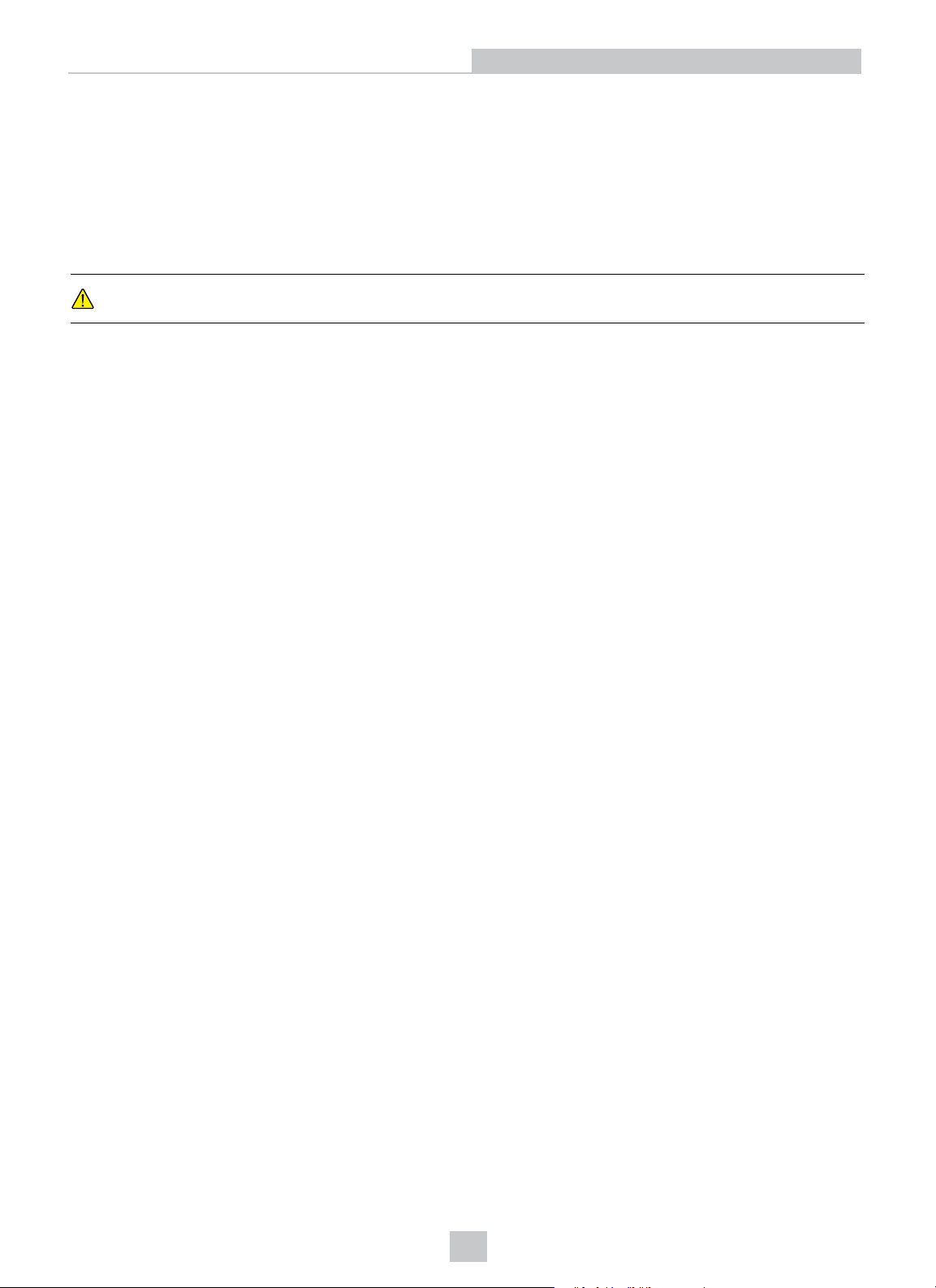
The following map shows the range of reading distances available for different code sizes and focus positions.
DataMan 8072 ER with a 12 mm Liquid Lens (Long Range, Focused to 8 meters)
26
Page 27
Cleaning and Maintenance
Cleaning and Maintenance
Cleaning the Reader Housing
To clean the outside of the reader housing, use a small amount of mild detergent cleaner or isopropyl alcohol on a
cleaning cloth. Do not pour the cleaner directly onto the reader housing.
CAUTION: Do not attempt to clean any DataMan product with harsh or corrosive solvents, including lye, methyl
ethyl ketone (MEK) or gasoline.
Cleaning the Reader Lens Cover
To remove dust from the lens cover, use a pressurized air duster. The air must be free of oil, moisture or other
contaminants that could remain on the lens cover. To clean the plastic window of the lens cover, use a small amount of
isopropyl alcohol on a cleaning cloth. Do not scratch the plastic window. Do not pour the alcohol directly on the plastic
window.
27
Page 28
Compliance Information, Warnings and Notices
Compliance Information, Warnings and Notices
Regulations/Conformity
The DataMan 8072 ER has Regulatory Model R00049, and meets or exceeds the requirements of all applicable
standards organizations for safe operation. However, as with any electrical equipment, the best way to ensure safe
operation is to operate them according to the agency guidelines that follow. Please read these guidelines carefully
before using your device.
Note: For the most current CE declaration and regulatory conformity information, see the Cognex support site:
cognex.com/support.
Regulator Specification
USA
Canada ICES-003, Class A
European Community
Japan
Korea KN32/KN35
FCC Part 15B, Class A
CE, Class A
EN55032
EN55024
VCCI - CISPR 32 Class A
Safety and Regulatory
Manufacturer
FCC FCC Part 15, Class A
Canadian
Compliance
Cognex Corporation
One Vision Drive
Natick, MA 01760 USA
This is a class A product. In a domestic environment this product may cause radio interference in
which case the user may be required to take immediate measures. This equipment complies with the
essential requirements of the EU Directive 2014/30/EU. Declarations are available from your local
representative.
This equipment has been tested and found to comply with the limits for a Class A digital device,
pursuant to part 15 of the FCC Rules. These limits are designed to provide reasonable protection
against harmful interference when the equipment is operated in a commercial environment. This
equipment generates, uses, and can radiate radio frequency energy and, if not installed and used in
accordance with the instruction manual, may cause harmful interference to radio communications.
Operation of this equipment in a residential area is likely to cause harmful interference in which case
the user will be required to correct the interference at his own expense.
This Class A digital apparatus complies with Canadian ICES-003. Cet appareil numérique de la
classe A est conforme à la norme NMB-003 du Canada.
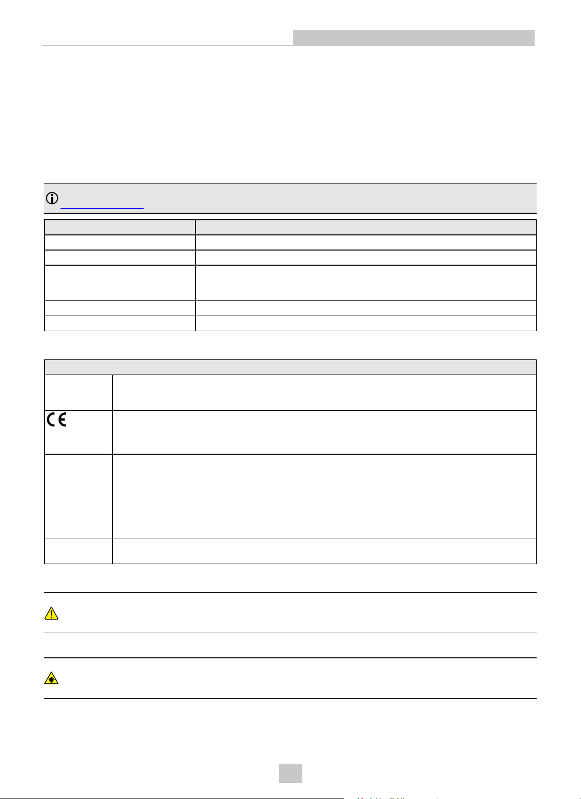
LED Safety Statement
CAUTION: Illumination and Lens assembly: This device has been tested in accordance with IEC 62471-1:2008
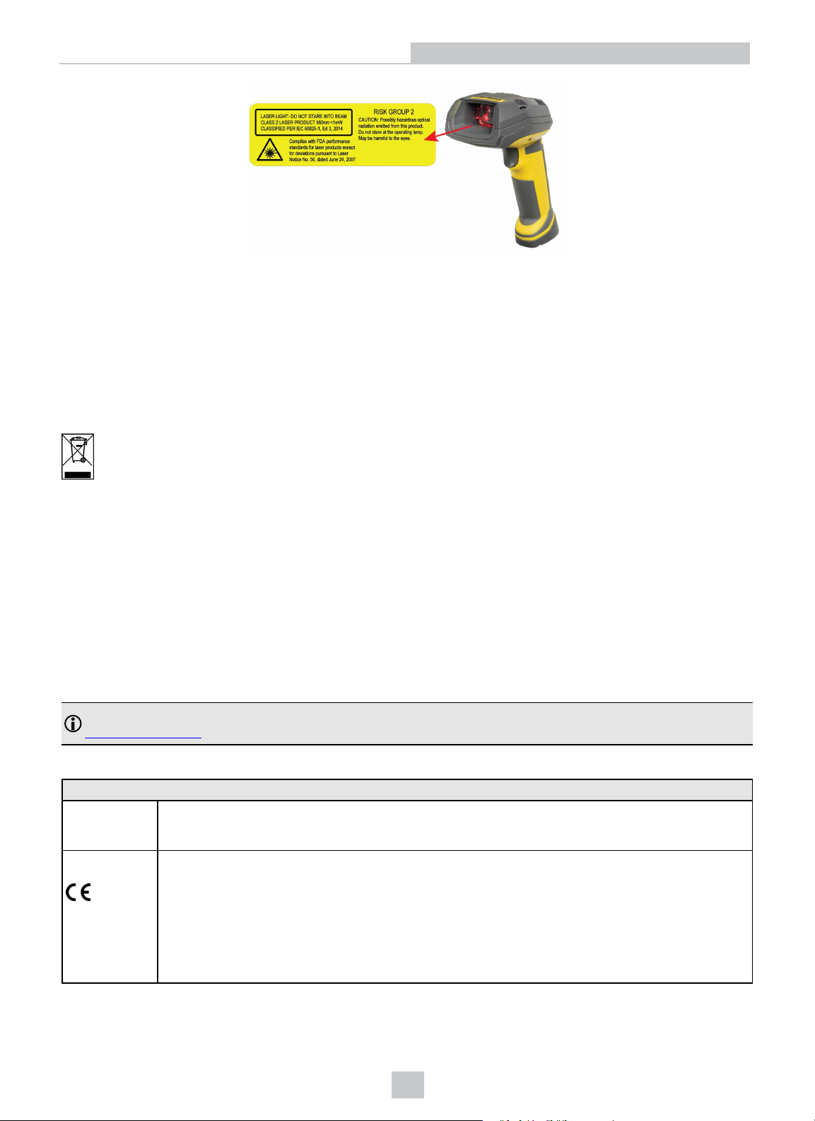
and has been certified to the limits of Risk Group 2. Possibly hazardous optical radiation emitted from this product.
Do not stare at the operating lamp. May be harmful to the eyes.
Laser Safety Statement
WARNING: Complies with FDA performance standards for laser products except for deviations pursuant to Laser
Notice No. 50, dated June 24, 2007. This device has been tested in accordance with IEC60825-1 3rd ed., and has
been certified to be under the limits of a Class 2 Laser device.
28
Page 29
Compliance Information, Warnings and Notices
For European Community Users
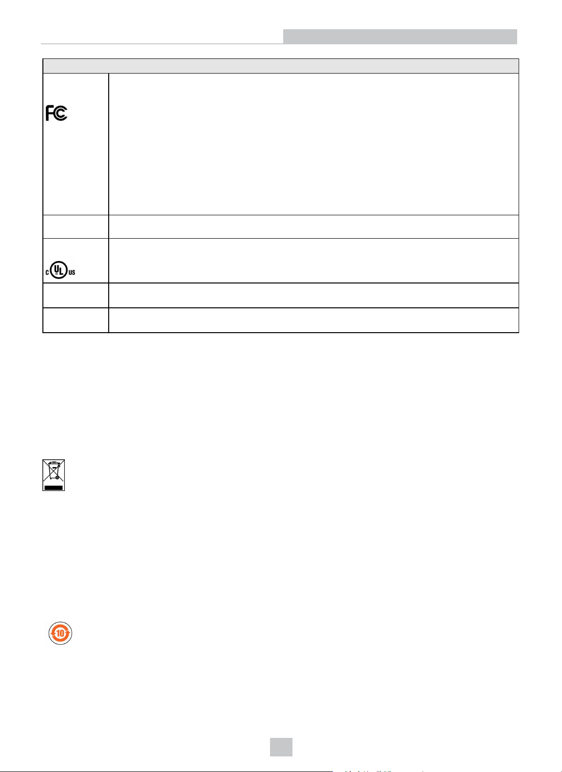
Cognex complies with Directive 2012/19/EU OF THE EUROPEAN PARLIAMENT AND OF THE COUNCIL of 4 July 2012
on waste electrical and electronic equipment (WEEE).
This product has required the extraction and use of natural resources for its production. It may contain hazardous
substances that could impact health and the environment, if not properly disposed.
In order to avoid the dissemination of those substances in our environment and to diminish the pressure on the natural
resources, we encourage you to use the appropriate take-back systems for product disposal. Those systems will reuse or
recycle most of the materials of the product you are disposing in a sound way.
The crossed out wheeled bin symbol informs you that the product should not be disposed of along with municipal
waste and invites you to use the appropriate separate take-back systems for product disposal.
If you need more information on the collection, reuse, and recycling systems, please contact your local or regional waste
administration.
You may also contact your supplier for more information on the environmental performance of this product.
Compliance Statements: DataMan Base Station
The DataMan Base Stations have the following Regulatory models respectively: DMA-IBASE-BT-02 has 1AAG, DMACBASE-01 has R00046, and they meet or exceed the requirements of all applicable standards organizations for safe
operation. However, as with any electrical equipment, the best way to ensure safe operation is to operate them
according to the agency guidelines that follow.
Note: For the most current CE declaration and regulatory conformity information, see the Cognex support site:
cognex.com/support.
Please read these guidelines carefully before using your device.
Safety and Regulatory
Manufacturer
European
Compliance
Cognex Corporation
One Vision Drive
Natick, MA 01760 USA
This is a class A product. In a domestic environment this product may cause radio interference in
which case the user may be required to take immediate measures. This equipment complies with the
essential requirements of the EU Directive 2014/30/EU. Declarations are available from your local
representative. DMA-IBASE-BT-XX: This equipment complies with the essential requirements of EU
Directives 2014/30/EU and 2014/53/EU as applicable. Declarations are available from your local
representative.
DMA-IBASE-01 and DMA-CBASE-01: This equipment complies with the essential requirements of EU
Directives 2014/30/EU and 2014/53/EU as applicable. Declarations are available from your local
representative.
29
Page 30
FCC Class A
Compliance
Statement
Canadian
Compliance
UL and cUL
Statement
Compliance Information, Warnings and Notices
Safety and Regulatory
This equipment has been tested and found to comply with the limits for a Class A digital device,
pursuant to part 15 of the FCC Rules. These limits are designed to provide reasonable protection
against harmful interference when the equipment is operated in a commercial environment.
This equipment generates, uses, and can radiate radio frequency energy and, if not installed and used
in accordance with the instruction manual, may cause harmful interference to radio communications.
Operation of this equipment in a residential area is likely to cause harmful interference in which case
the user will be required to correct the interference at his own expense.
This device complies with Part 15 of the FCC Rules and with RSS-210 of Industry Canada.
Operation is subject to the following two conditions:
(1) this device may not cause harmful interference, and
(2) this device must accept any interference received, including interference that may cause undesired
operation.
Changes or modifications made to this equipment not expressly approved by Cognex may void the
FCC authorization to operate this equipment.
This Class A digital apparatus complies with Canadian ICES-003. Cet appareil numérique de la
classe A est conforme à la norme NMB-003 du Canada.
UL and cUL listed: UL60950-1 2nd ed. and CSA C22.2 No.60950-1 2nd ed.
Mexican
Compliance
Chinese
Compliance
DMA-IBASE-BT-XX: RCPCO1A15-0073
DMA-IBASE-01: RCPCODM12-0655
DMA-IBASE-BT-XX: CMIIT ID: 2015DJ0237
DMA-IBASE-01: CMIIT ID: 2012DJ2857
For European Community Users
Cognex complies with Directive 2012/19/EU OF THE EUROPEAN PARLIAMENT AND OF THE COUNCIL of 4 July 2012
on waste electrical and electronic equipment (WEEE).
This product has required the extraction and use of natural resources for its production. It may contain hazardous
substances that could impact health and the environment, if not properly disposed.
In order to avoid the dissemination of those substances in our environment and to diminish the pressure on the natural
resources, we encourage you to use the appropriate take-back systems for product disposal. Those systems will reuse or
recycle most of the materials of the product you are disposing in a sound way.
The crossed out wheeled bin symbol informs you that the product should not be disposed of along with municipal
waste and invites you to use the appropriate separate take-back systems for product disposal.
If you need more information on the collection, reuse, and recycling systems, please contact your local or regional waste
administration.
You may also contact your supplier for more information on the environmental performance of this product.
中 国 大 陆 RoHS (Information for China RoHS Compliance)
根据中国大陆《电子信息产品污染控制管理办法》(也称 为 中 国 大 陆 RoHS),以下部份列出了本产品中可能包含的有
毒有害物质或元素的名称和含量。
Table of toxic and hazardous substances/elements and their content, as required by China’s management methods for
controlling pollution by electronic information products.
30
Page 31
Compliance Information, Warnings and Notices
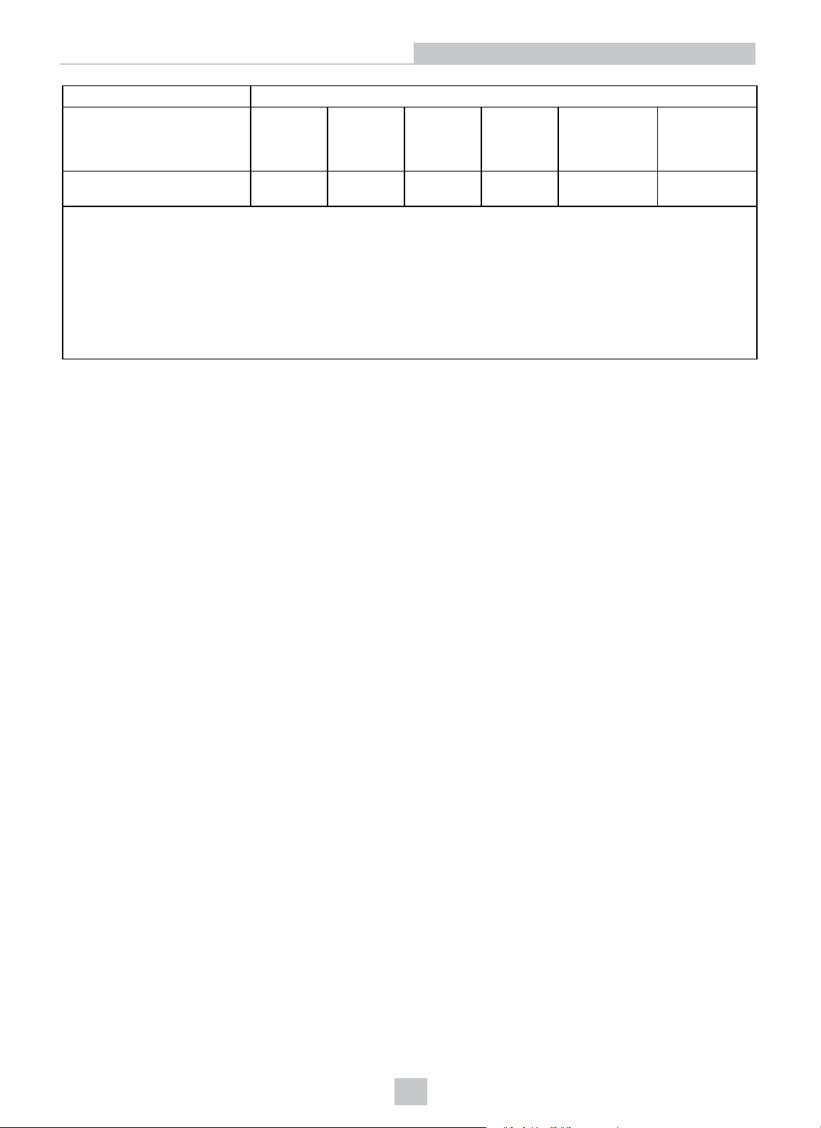
Hazardous Substances 有 害 物 质
Part Name
部件名称
Regulatory Model R00049
Base Station
This table is prepared in accordance with the provisions of SJ/T 11364.
这个标签是根据SJ / T 11364 的 规 定 准 备 的 。
O: Indicates that said hazardous substance contained in all of the homogeneous materials for this part is below the limit
requirement of GB / T26572 - 2011.
表示本部件所有均质材料中含有的有害物质低于GB / T26572 - 2011 的 限 量 要 求 。
X: Indicates that said hazardous substance contained in at least one of the homogeneous materials used for this part is
above the limit requirement of GB / T26572 - 2011.
表示用于本部件的至少一种均质材料中所含的危害物质超过GB / T26572 - 2011 的 限 制 要 求 。
Lead (Pb)铅Mercury
(Hg)
汞
X O O O O O
Cadmium
(Cd)
镉
Hexavalent
Chromium
(Cr (VI))
六价铬
Polybrominated
biphenyls
(PBB)
多溴联苯
Polybrominated
diphenyl ethers
(PBDE)
多溴二苯醚
31
Page 32

Precautions
Precautions
WARNING: LASER LIGHT, DO NOT STARE INTO BEAM: CLASS 2 LASER PRODUCT. FAILURE TO FOLLOW
THESE INSTRUCTIONS MAY CAUSE SERIOUS INJURY.
To reduce the risk of injury or equipment damage, observe the following precautions when you install the Cognex
product:
l Route cables and wires away from high-current wiring or high-voltage power sources to reduce the risk of
damage or malfunction from the following causes: over-voltage, line noise, electrostatic discharge (ESD), power
surges, or other irregularities in the power supply.
l Changes or modifications not expressly approved by the party responsible for regulatory compliance could void
the user’s authority to operate the equipment.
l Ensure that the cable bend radius begins at least six inches from the connector. Cable shielding can be
degraded or cables can be damaged or wear out faster if a service loop or bend radius is tighter than 10X the
cable diameter.
l This device should be used in accordance with the instructions in this manual.
l All specifications are for reference purposes only and can change without notice.
32
Page 33

Copyright © 2019
Cognex Corporation. All Rights Reserved.
 Loading...