

Page 1

DataMan
®
Fixed Mount Readers
Reference Manual
04/19/2017
Version: 5.7.0.36
Page 2

Legal Notices
The software described in this document is furnished under license, and may be used or copied only in accordance with
the terms of such license and with the inclusion of the copyright notice shown on this page. Neither the software, this
document, nor any copies thereof may be provided to, or otherwise made available to, anyone other than the licensee.
Title to, and ownership of, this software remains with Cognex Corporation or its licensor. Cognex Corporation assumes
no responsibility for the use or reliability of its software on equipment that is not supplied by Cognex Corporation.
Cognex Corporation makes no warranties, either express or implied, regarding the described software, its
merchantability, non-infringement or its fitness for any particular purpose.
The information in this document is subject to change without notice and should not be construed as a commitment by
Cognex Corporation. Cognex Corporation is not responsible for any errors that may be present in either this document or
the associated software.
Companies, names, and data used in examples herein are fictitious unless otherwise noted. No part of this document
may be reproduced or transmitted in any form or by any means, electronic or mechanical, for any purpose, nor
transferred to any other media or language without the written permission of Cognex Corporation.
Copyright © 2017. Cognex Corporation. All Rights Reserved.
Portions of the hardware and software provided by Cognex may be covered by one or more U.S. and foreign patents, as
well as pending U.S. and foreign patents listed on the Cognex web site at: http://www.cognex.com/patents.
The following are registered trademarks of Cognex Corporation:
Cognex, 2DMAX, Advantage, AlignPlus, Assemblyplus, CheckitwithChecker, Checker, CognexVisionforIndustry,
CognexVSOC, CVL, DataMan, DisplayInspect, DVT, EasyBuilder, Hotbars, IDMax, In-Sight, LaserKiller, MVS-8000,
OmniView, PatFind, PatFlex, PatInspect, PatMax, PatQuick, SensorView, SmartView, SmartAdvisor, SmartLearn,
UltraLight, VisionSolutions, VisionPro, VisionView
The following are trademarks of Cognex Corporation:
The Cognex logo, 1DMax, 3D-Locate, 3DMax, BGAII, CheckPoint, CognexVSoC, CVC-1000, FFD, iLearn, In-Sight
(design insignia with cross-hairs), In-Sight2000, InspectEdge, Inspection Designer, MVS, NotchMax, OCRMax,
PatMaxRedLine, ProofRead, SmartSync, ProfilePlus, SmartDisplay, SmartSystem, SMD4, VisiFlex, Xpand
Other product and company trademarks identified herein are the trademarks of their respective owners.
2
Legal Notices
Page 3

Table of Contents
Legal Notices 2
Table of Contents 3
About This Manual 6
Symbols 6
Safety Information 7
Warnings And Notices 7
Mechanical Information 8
DataMan 50 Reader Dimensions 8
DataMan 60 Reader Dimensions 9
DataMan 70 Series Reader Dimensions 10
DataMan 150 Reader Dimensions 11
DataMan 260 Reader Dimensions 12
DataMan 300 Series Reader Dimensions 13
DataMan 360 Series Reader Dimensions 15
DataMan 503 Reader Dimensions 16
Service Procedures 17
DataMan 50 Service Procedures 17
DataMan 60 Service Procedures 18
DataMan 70 Service Procedures 19
DataMan 150 and 260 Series Service Procedures 21
DataMan 300 and 360 Series Service Procedures 25
DataMan 503 Service Procedures 34
Mounting Requirements 35
Grounding 36
Thermal and Environmental Requirements 37
DataMan 50, 150, 260, 300, 360 and 503 IP Rating 37
DataMan 60 and 70 IP Rating 37
Electrical Information 38
DataMan 50 and 60 Discrete I/O Connector 38
DataMan 50 and 60 USB & Flying Leads I/O Cable 38
DataMan 50 and 60 RS-232 & Flying Leads I/O Cable 39
DataMan 50 and 60 Digital Input Lines 39
DataMan 50 and 60 External Wiring Examples: Digital Input Lines 40
DataMan 50 and 60 Digital Output Lines 41
DataMan 50 and 60 External Wiring Examples: Digital Output Lines 43
DataMan 70 and 150 Discrete I/O Connector 44
DataMan 70 and 150 RS-232 Cable 44
DataMan 150 Flying Leads Cable 45
DataMan 260 Discrete I/O Connector 46
DataMan 260 Ethernet Cable 47
DataMan 260 Acquisition Triggering 48
DataMan 260 High-Speed Output Lines 49
DataMan 260 High-Speed Output Wiring 49
DataMan 300 and 360 Series Readers Discrete I/O Connector 51
DataMan 300 and 360 Series Readers External Light Control 52
3
Table of Contents
Page 4

DataMan 300 and 360 Series Readers Power Requirements 52
DataMan 300 and 360 Series Readers Acquisition Triggering 52
DataMan 300 and 360 Series Readers High Speed Output Lines 52
DataMan 300 and 360 Series Readers High Speed Output Wiring 54
DataMan 503 Discrete I/O Connector 55
DataMan 503 RS-232 Serial Connector 55
DataMan 503 External Light Control 56
DataMan 503 High-Speed Output Wiring 56
DataMan 503 Power Requirements 57
Connecting the Encoder to a DataMan 58
Optics and Lighting 59
DataMan 50 and 60 Reading Distances and Field of View 59
DataMan 70, 150 and 260 Reading Distances and Field of View 61
DataMan 300 and 360 Series Readers Reading Distances and Field of View 66
Scan Map for DataMan 300 and 360 Series Readers Using a 10.3 mm Lens 66
Scan Map for DataMan 300 and 360 Series Readers Using a 16 mm Lens 67
Scan Map for DataMan 300 and 360 Series Readers Using a 19 mm Lens 68
Scan Map for DataMan 300 and 360 Series Readers Using a 25 mm Lens 69
DataMan 503 Readers Reading Distance and Field of View 70
Scan Map for DataMan 503 Series Readers Using a 16 mm Lens Module 70
Scan Map for DataMan 503 Series Readers Using a 25 mm Lens Module 71
Scan Map for DataMan 503 Series Readers Using a 35 mm Lens Module 71
CS-Mount Lens Characteristics 72
DataMan 503 CS-Mount Lens Characteristics 72
Internal Lighting 73
DataMan 50 and 60 Internal Lighting 73
DataMan 70, 150 and 260 Internal Lighting 73
DataMan 300 and 360 Series Readers Internal Lighting 73
External Lighting 76
DataMan 50 and 60 External Lighting 76
DataMan 50 and 60 Illumination Strobe Output 76
DataMan 50 and 60 External Load Strobe Output 78
DataMan 300 and 360 Series Readers External Lighting 78
DataMan 50, 60, 300 and 360 External Lighting Duration 80
DataMan 503 External Lighting Duration 81
Operations Guide 82
Trigger Modes 82
Self-Trigger 82
Manual 82
Burst 82
Continuous 82
Single 82
Presentation 82
Package Detection Support 83
Test Mode 83
Code Training 84
Automatic Code Training for DPM Symbols 84
Image Buffering and Image Recording 84
Retrieving Buffered Images 85
4
Table of Contents
Page 5

DataMan Master/Slave Configuration 85
Master 85
Slaves 86
Data Formatting 86
Limitations 86
Synchronized Acquisition 86
Using C/CS-Mount Lenses 88
Aperture Setting 88
Selecting Optimum Focus 88
Optimizing Performance 88
Read Interval and Timeout Configuration 88
Optimizing Burst Trigger Parameters 88
Reducing DataMan Processing Requirements 89
Avoiding Reflections and Glare 89
Application Guide 90
Understanding Your Application Envelope 90
Tote Scanning 91
Side Scanning 92
Side Scanning (Large Field) 92
Print Verification (Carton Coding and Print & Apply) 93
Manual Presentation Scanning 94
Precautions 95
5
Table of Contents
Page 6
About This Manual
The DataMan Fixed Mount Readers Reference provides detailed information on the configuration and operation of
DataMan fixed-mount readers. It includes the following sections:
l Safety Information
l Mechanical Information
l Electrical Information
l Optics and Lighting
l Operation
l Application Guide
Symbols
The following symbols indicate safety precautions and supplemental information.
WARNING: This symbol indicates the presence of a hazard that could result in death, serious personal injury or
electrical shock.
CAUTION: This symbol indicates the presence of a hazard that could result in property damage.
Note: Notes provide supplemental information about a subject.
Tip: Tips provide helpful suggestions and shortcuts that may not otherwise be apparent.
6
About This Manual
Page 7
Safety Information
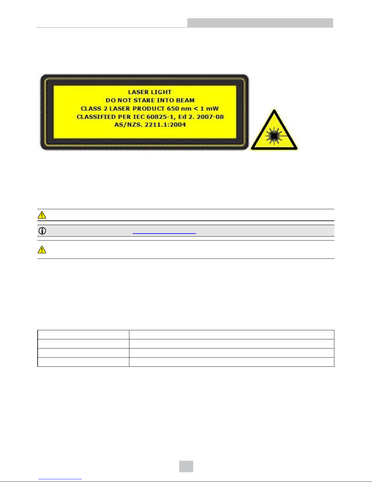
The DataMan 300, 360, and 503 series readers have laser light.
If you need more information on the collection, reuse, and recycling systems, please contact your local or regional waste
administration.
You may also contact your supplier for more information on the environmental performance of this product.
Warnings And Notices
CAUTION: IP protection is ensured only when all connectors are attached to cables or shielded by a sealing cap.
Note: For product support, contact http://support.cognex.com.
CAUTION: Use of controls or adjustments or performance of procedures other than those specified herein may
result in hazardous radiation exposure.
l Do not attempt to service or repair this product - return it to Cognex for service.
l Do not permit anyone other than Cognex Corporation to service, repair, or adjust this product.
l Do not attempt to open or modify this device except as described in this document.
l Do not direct or reflect laser light toward people or reflective objects.
l Do not operate this device if it is damaged or if the covers or seals are missing or damaged.
This Laser Product is designated as Class 2 during all procedures of operation.
Wavelength 650 nm
Laser power for classification < 1mW
Beam Diameter < 3mm at aperture
Divergence < 1.5 mrad
7
Safety Information
Page 8
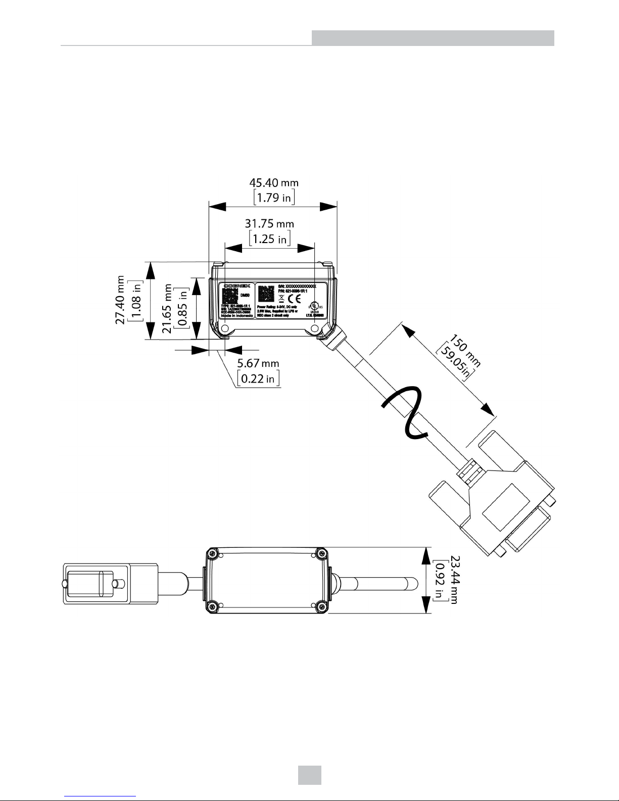
Mechanical Information
This section provides information on various mechanical features of the DataMan 50, DataMan 60, DataMan 70,
DataMan 150, DataMan 260, DataMan 300, DataMan 360 and DataMan 503 series readers, such as dimensions, lens
replacement, mounting information, as well as thermal and environmental requirements.
DataMan 50 Reader Dimensions
8
Mechanical Information
Page 9
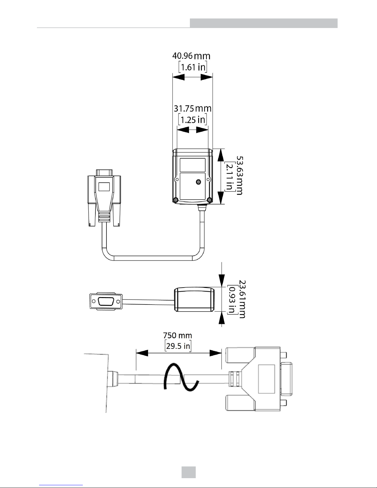
DataMan 60 Reader Dimensions
9
Mechanical Information
Page 10
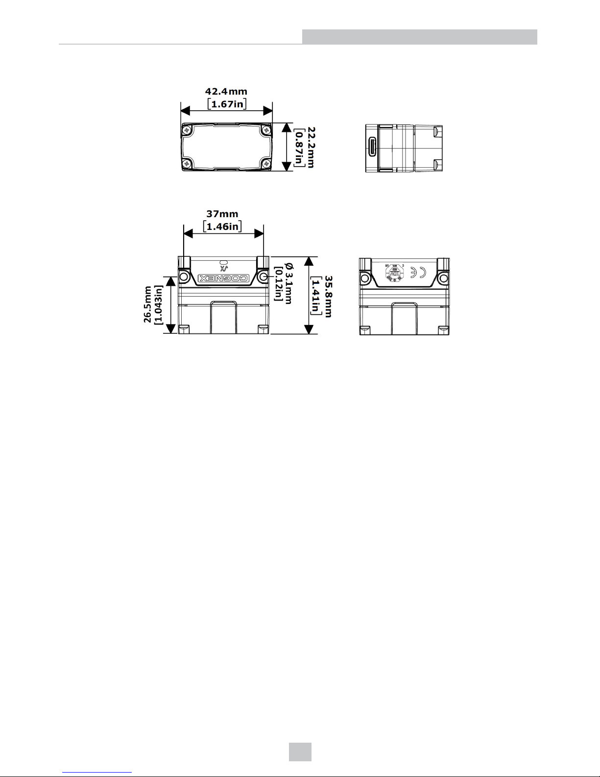
DataMan 70 Series Reader Dimensions
10
Mechanical Information
Page 11
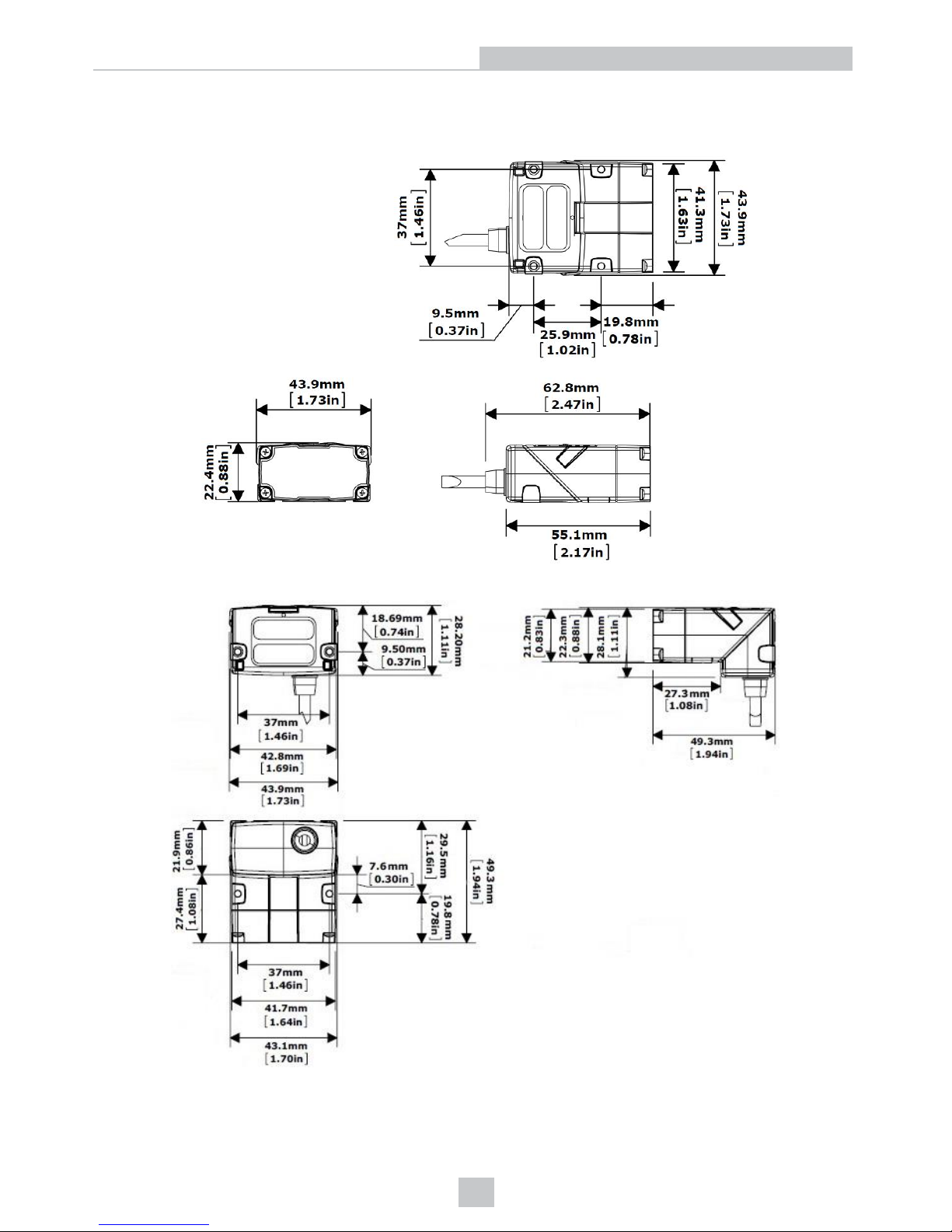
DataMan 150 Reader Dimensions
DataMan 150 dimensions in the straight configuration:
DataMan 150 dimensions in the angled configuration:
11
Mechanical Information
Page 12
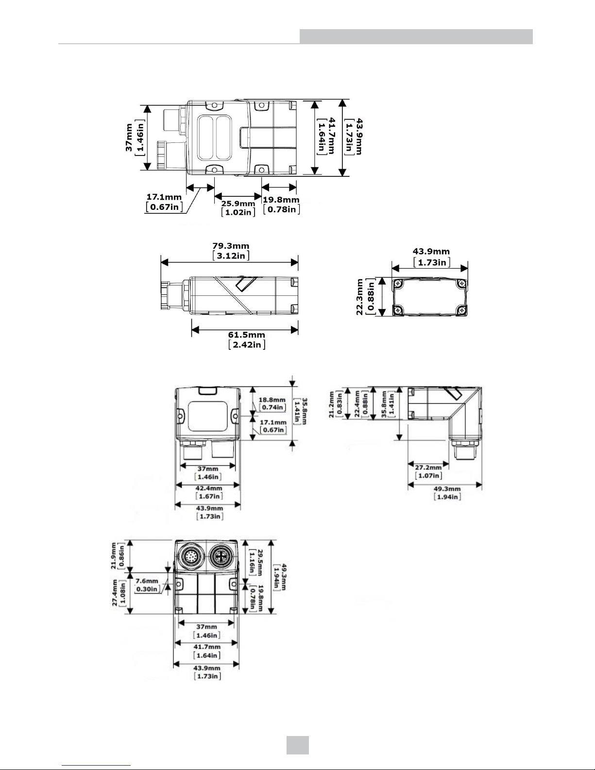
DataMan 260 Reader Dimensions
DataMan 260 dimensions in the straight configuration:
DataMan 260 dimensions in the angled configuration:
12
Mechanical Information
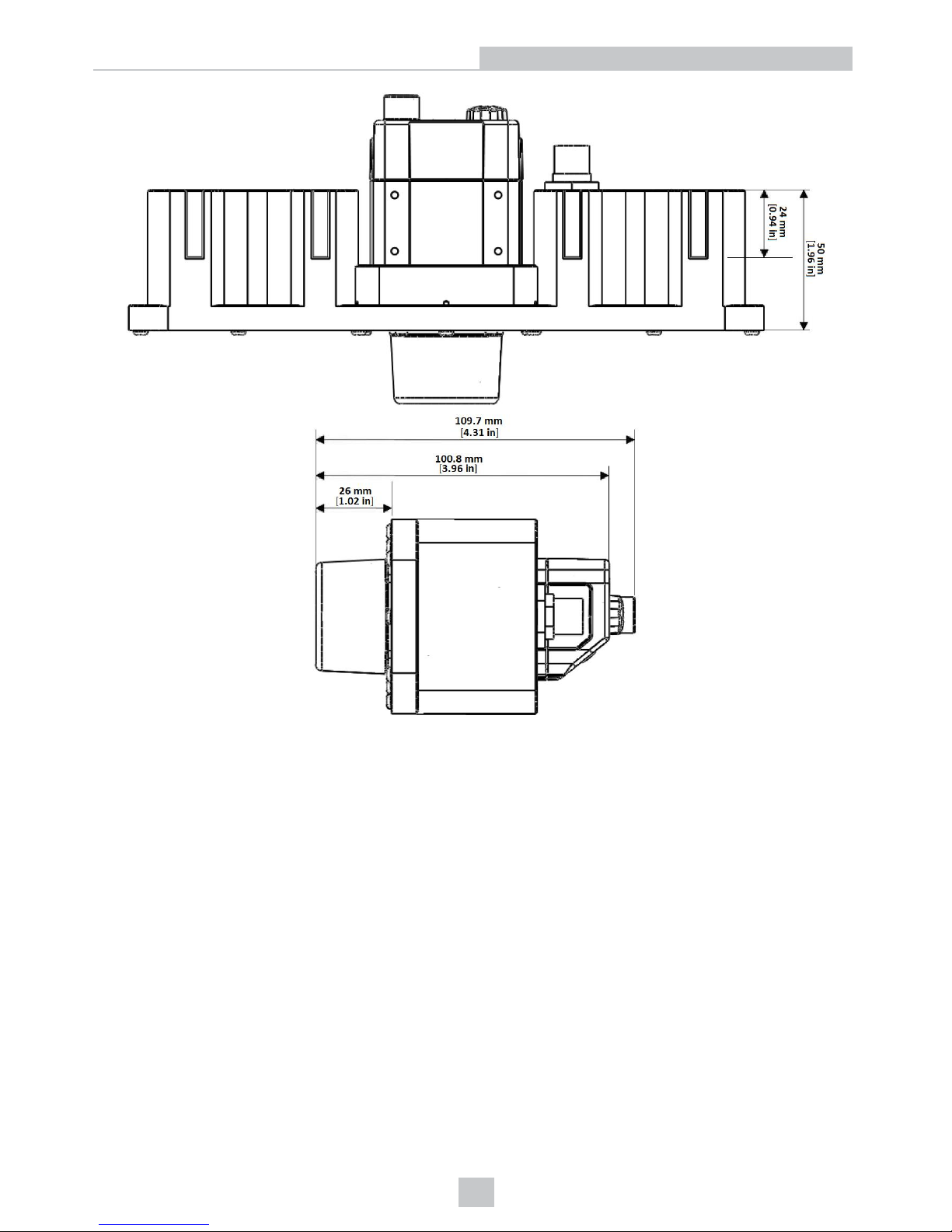
Page 13
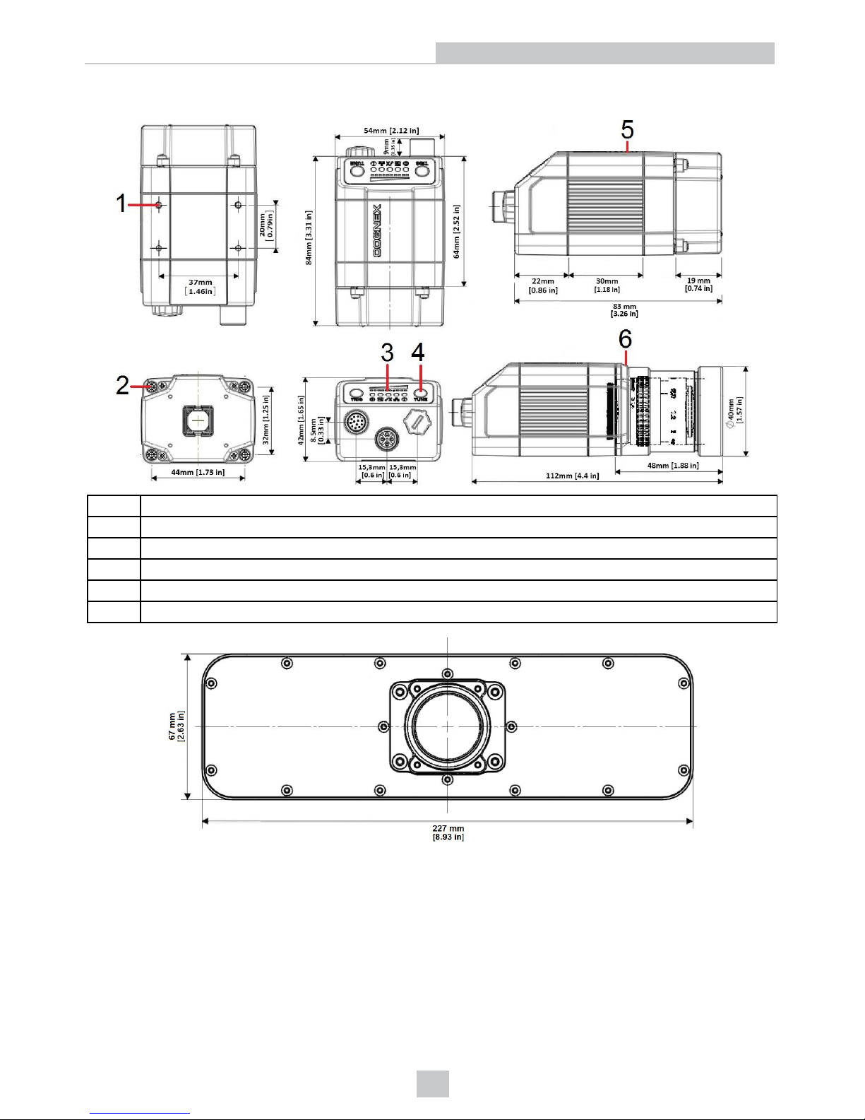
DataMan 300 Series Reader Dimensions
1 M3-5 (4x) mounting holes of the device
2 M3-6 (4x) mounting holes for external illumination
3 Illumination lights
4 Operating buttons
5 S-Mount (M12) Lens version
6 C-Mount Lens version
13
Mechanical Information
Page 14
14
Mechanical Information
Page 15
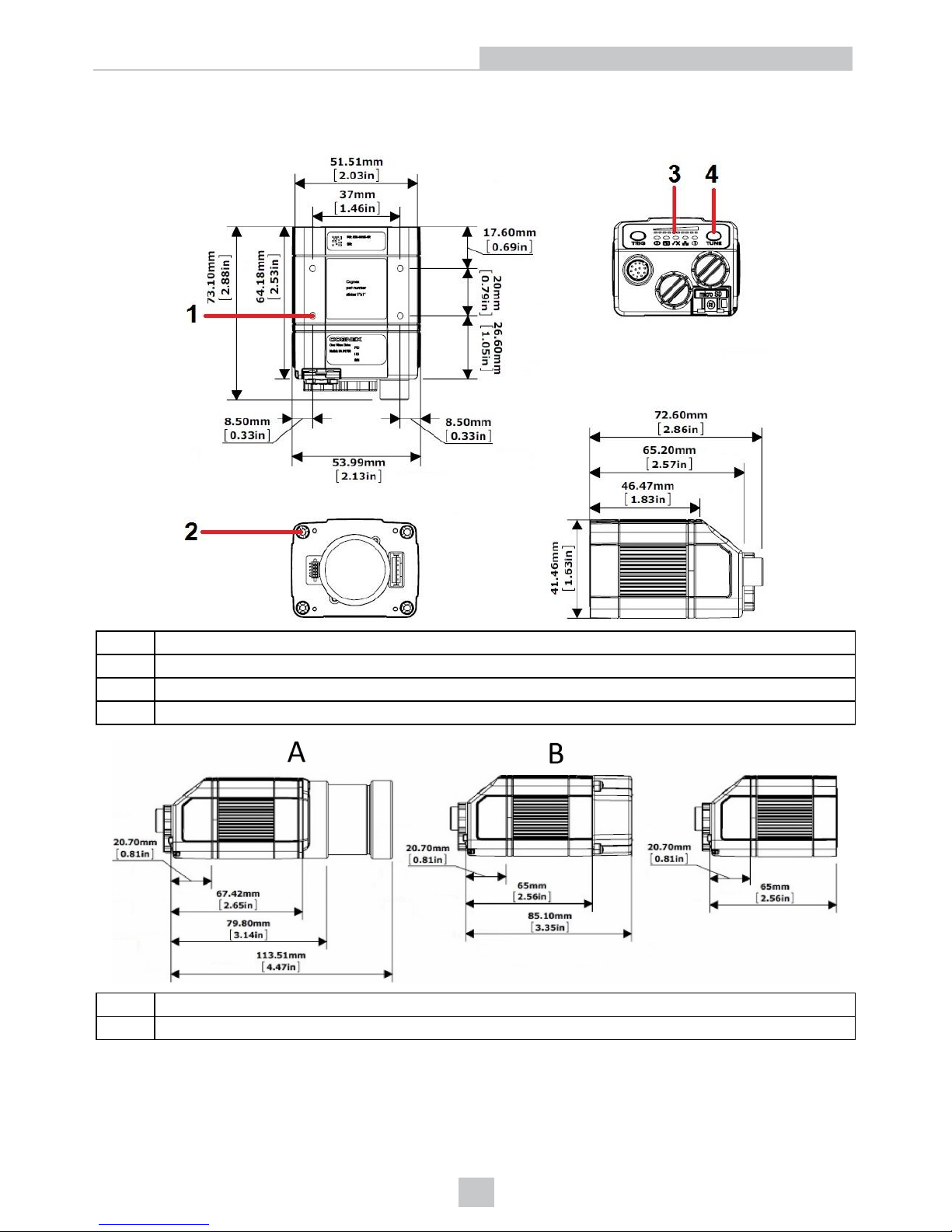
DataMan 360 Series Reader Dimensions
DataMan 360 dimensions without lens and with C-mount and S-mount lens options:
1 M3-5 (4x) mounting holes of the device
2 M3-6 (4x) mounting holes for external illumination
3 Illumination lights
4 Operating buttons
A C-Mount Lens version
B S-Mount (M12)Lens version
15
Mechanical Information
Page 16
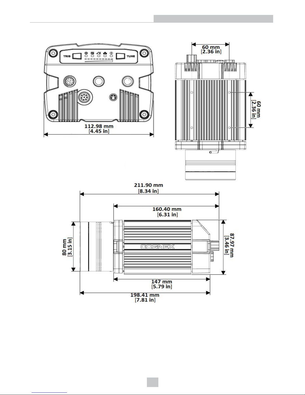
DataMan 503 Reader Dimensions
16
Mechanical Information
Page 17
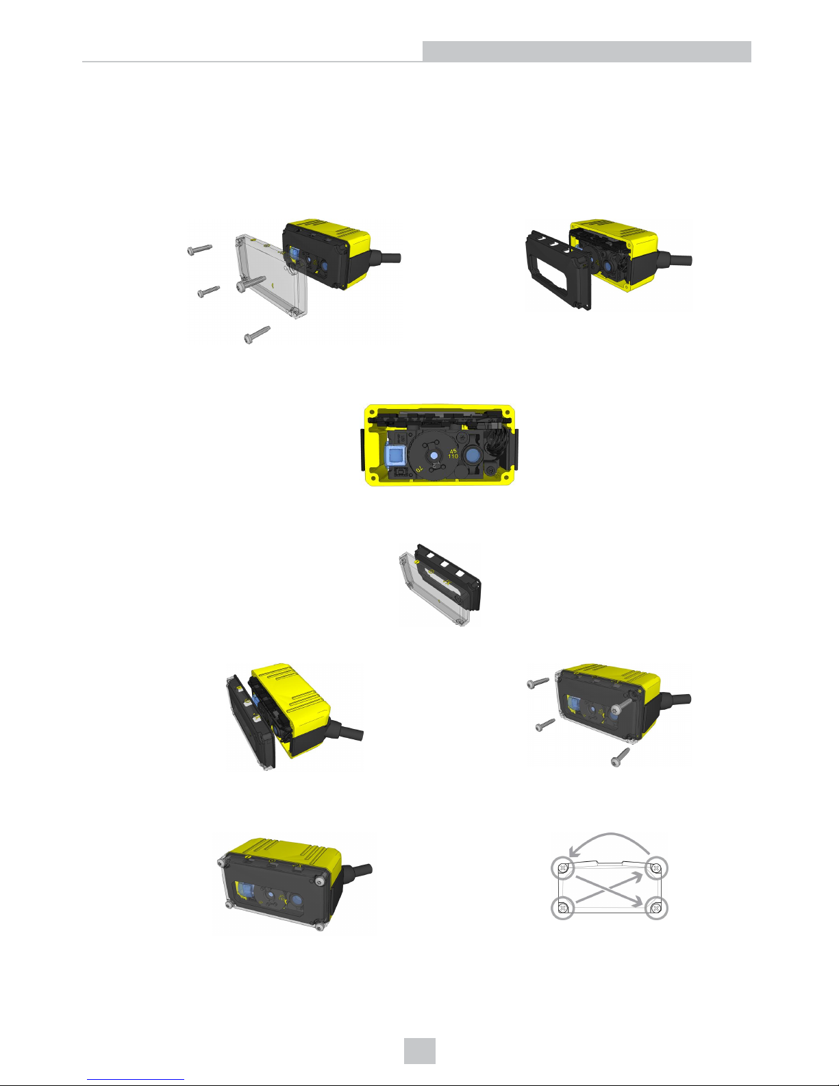
Service Procedures
DataMan 50 Service Procedures
DataMan 50 can operate in one of three distance ranges. Perform the following steps to set the focus position:
1. Remove the screws, the lens cover and the rubber part.
2. Set the focus position using a coin. Do not use a coin thicker than 2 mm. If no coin is available, use the edge of
the back cover.
3. Make sure that the sealing and the sealing surface are clean before mounting.
4. Line up the holes with the icons and attach the rubber part to the front window.
5. Attach both to the housing and add the four screws.
6. Tighten the screws in the order shown in the image below. The maximum torque for the cover screws is 8 N-cm
(0.7 pound-inch).
17
Mechanical Information
Page 18
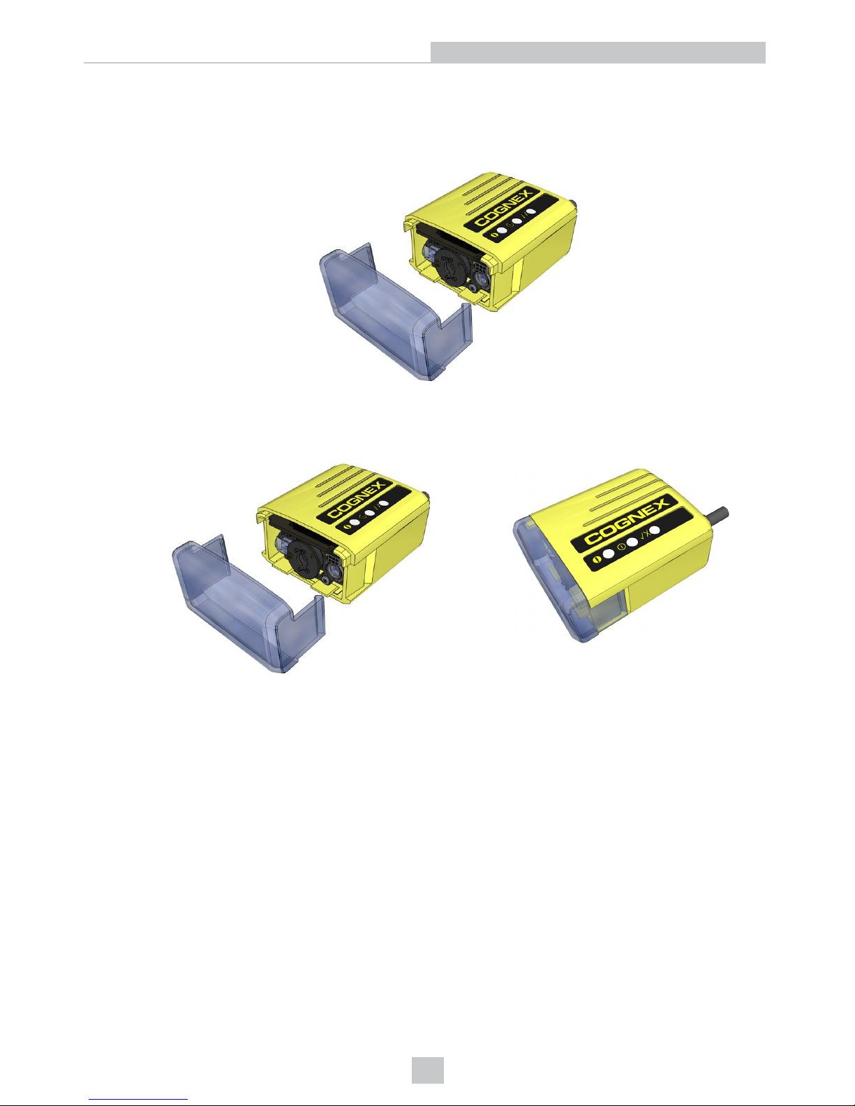
DataMan 60 Service Procedures
DataMan 60 can operate in one of three distance ranges. Perform the following steps to set the focus position:
1. Remove the lens cover.
2. Set the focus position to 45, 70, or 110: turn the lens cap clockwise (45->70->110) to focus to a larger distance;
turn the lens cap counter-clockwise (110->70->45) to focus to a shorter distance.
3. Reattach the front cover.
18
Mechanical Information
Page 19
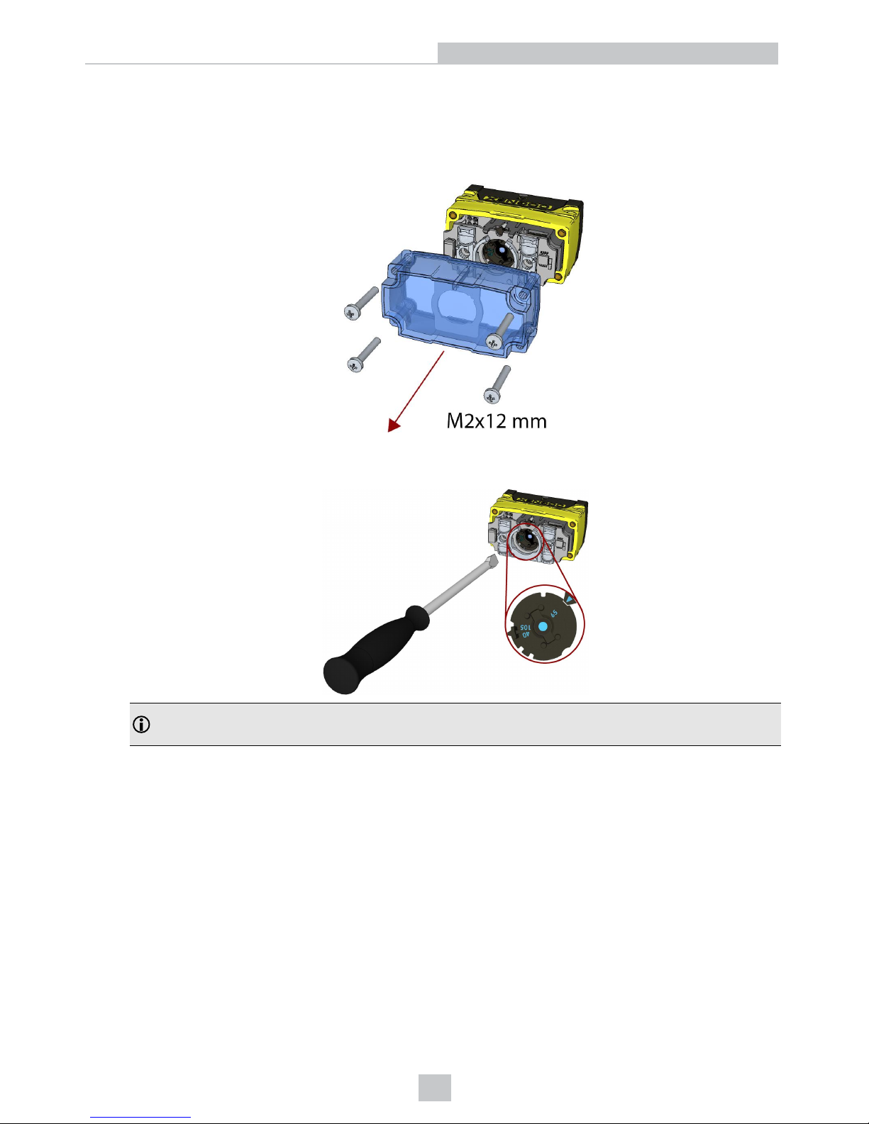
DataMan 70 Service Procedures
DataMan 70 can operate in one of three distance ranges. Follow the steps below to set the focus position.
1. Remove the screws and the front cover.
2. Using a flathead screwdriver, set the focus position from the front. Always turn clockwise to focus to a larger
distance and counterclockwise to focus to a shorter distance.
Note: If an optical filter has been mounted, first disconnect the DataMan 70 reader from power and remove
the illumination module with the filter before adjusting the focus.
19
Mechanical Information
Page 20
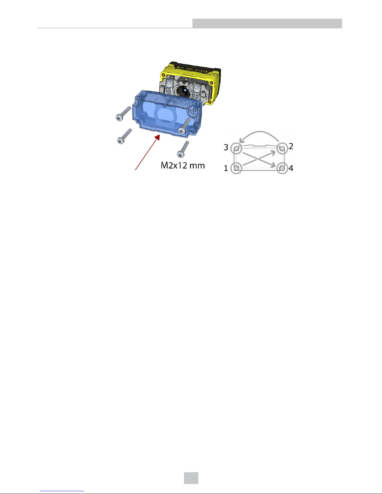
3. Remount the front cover. Observing the tightening sequence below, tighten all four screws to 9 Ncm using a
torque wrench.
20
Mechanical Information
Page 21
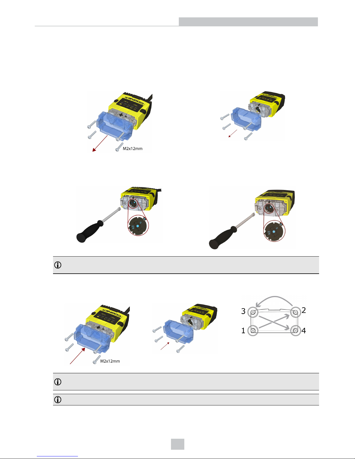
DataMan 150 and 260 Series Service Procedures
Setting the Focus Position of a DataMan 150 or DataMan 260 Reader
DataMan 150 and 260 can operate in one of three distance ranges. Follow the steps below to set the focus position.
1. Remove the screws and the front cover.
DataMan 150 DataMan 260
2. Using a flathead screwdriver, set the focus position from the front. Always turn clockwise to focus to a larger
distance and counterclockwise to focus to a shorter distance.
DataMan 150 DataMan 260
Note: If an optical filter has been mounted, first disconnect the DataMan 150 or 260 reader from power and
remove the illumination module with the filter before adjusting the focus.
3. Remount the front cover. Observing the tightening sequence below, tighten all four screws to 9 Ncm using a
torque wrench.
DataMan 150 DataMan 260
Note: If you use an optical filter and the illumination was removed, remount the illumination module first and
then remount the front cover.
Note: The rib in the front cover must be oriented to the top side.
21
Mechanical Information
Page 22
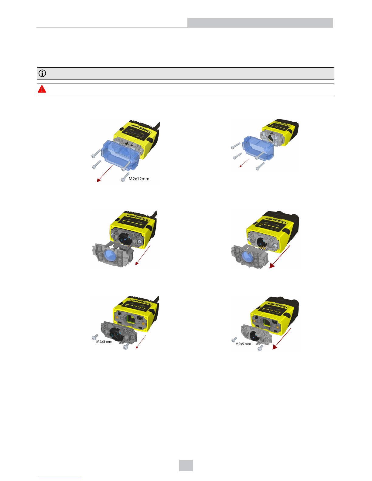
Changing from a 6.2 mm Lens to a 16 mm Lens on a DataMan 150 or DataMan 260
Reader
Perform the following steps to change a 6.2 mm lens to a 16 mm lens on your DataMan 150 or 260 reader.
Note: Disconnect the DataMan 150 or 260 reader from power before changing lenses.
WARNING: This modification must be made in a dust-free and ESD safe area.
1. Remove the front cover: unscrew the four screws and take off the LEDcover.
DataMan 150 DataMan 260
2. Remove the illumination module.
DataMan 150 DataMan 260
3. Unscrew the two Phillips head screws and remove the 6.2 mm lens mount.
DataMan 150 DataMan 260
22
Mechanical Information
Page 23
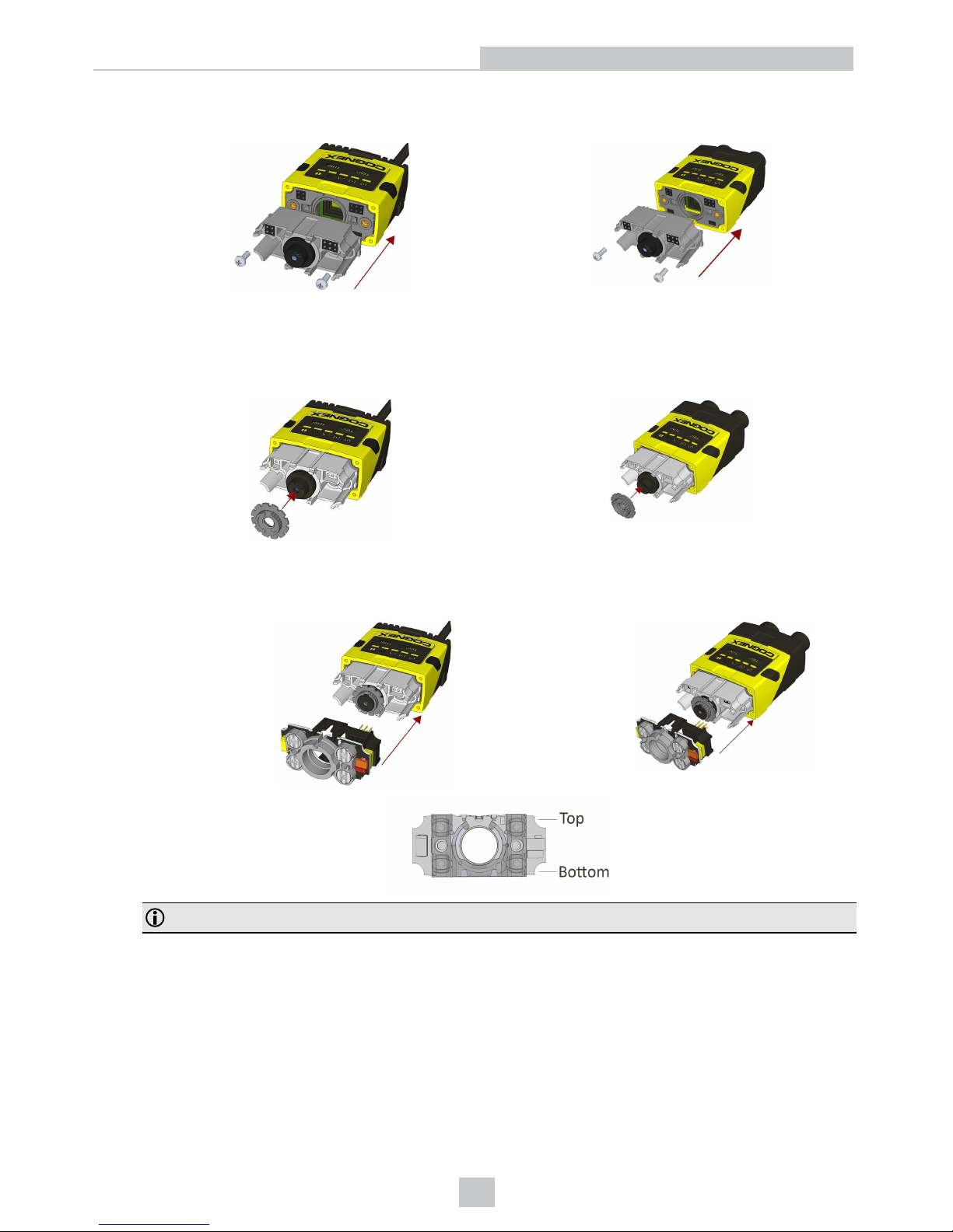
4. Attach the 16 mm lens mount.
DataMan 150 DataMan 260
5. Fasten the two Phillips head screws to 0.06 Nm using a torque wrench.
6. In the case of a manual focus lens, press the 16 mm lens cap onto the lens. The lens has 12 cutouts so it can be
locked in steps of 30 degrees.
DataMan 150 DataMan 260
7. Attach the illumination board.
DataMan 150 DataMan 260
Note: Take care to attach the illumination with the right orientation.
23
Mechanical Information
Page 24
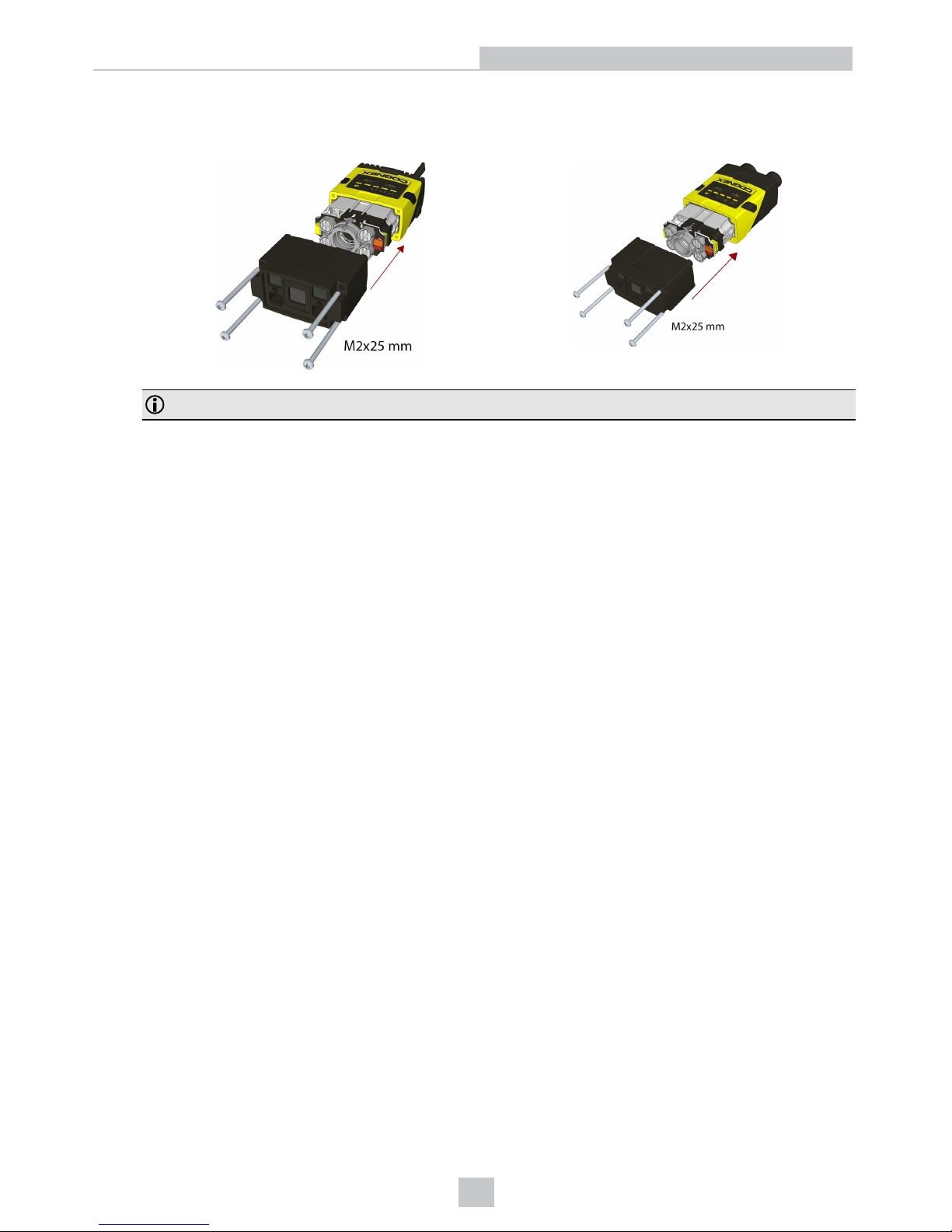
8. Attach the extended front cover. Observing the tightening sequence below, tighten all four screws to 9 Ncm using
a torque wrench.
DataMan 150 DataMan 260
Note: The rib in the front cover must be oriented to the top side.
24
Mechanical Information
Page 25
DataMan 300 and 360 Series Service Procedures
Replacing a 10.3 mm Lens
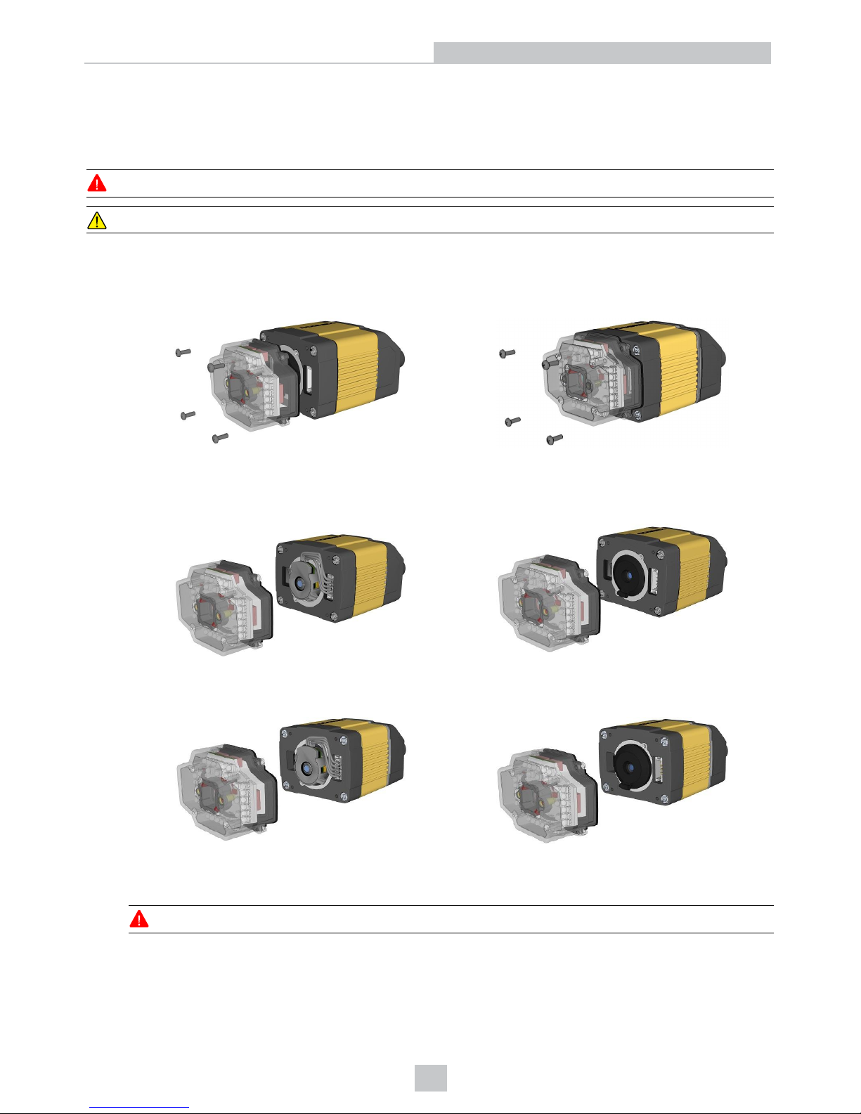
To remove and replace a 10.3 mm lens of a DataMan 300 or 360 series reader, perform the following steps:
WARNING: Disconnect the DataMan reader from power before continuing.
CAUTION: Do not leave the image sensor exposed to the environment.
1. Remove and retain the four screws at the corners of the front cover.
DataMan 300 DataMan 360
2. Remove the front cover. The first image shows a reader with a liquid lens attached to the 10.3 mm lens. The
second image shows a reader with a 10.3 mm lens only.
DataMan 300
DataMan 360
3. If you have a liquid lens module attached to your 10.3 mm lens, carefully disconnect the liquid lens module cable.
If you only have a 10.3 mm lens inserted, jump to step 5 of this procedure.
WARNING: Do not pinch or pull the cable.
25
Mechanical Information
Page 26
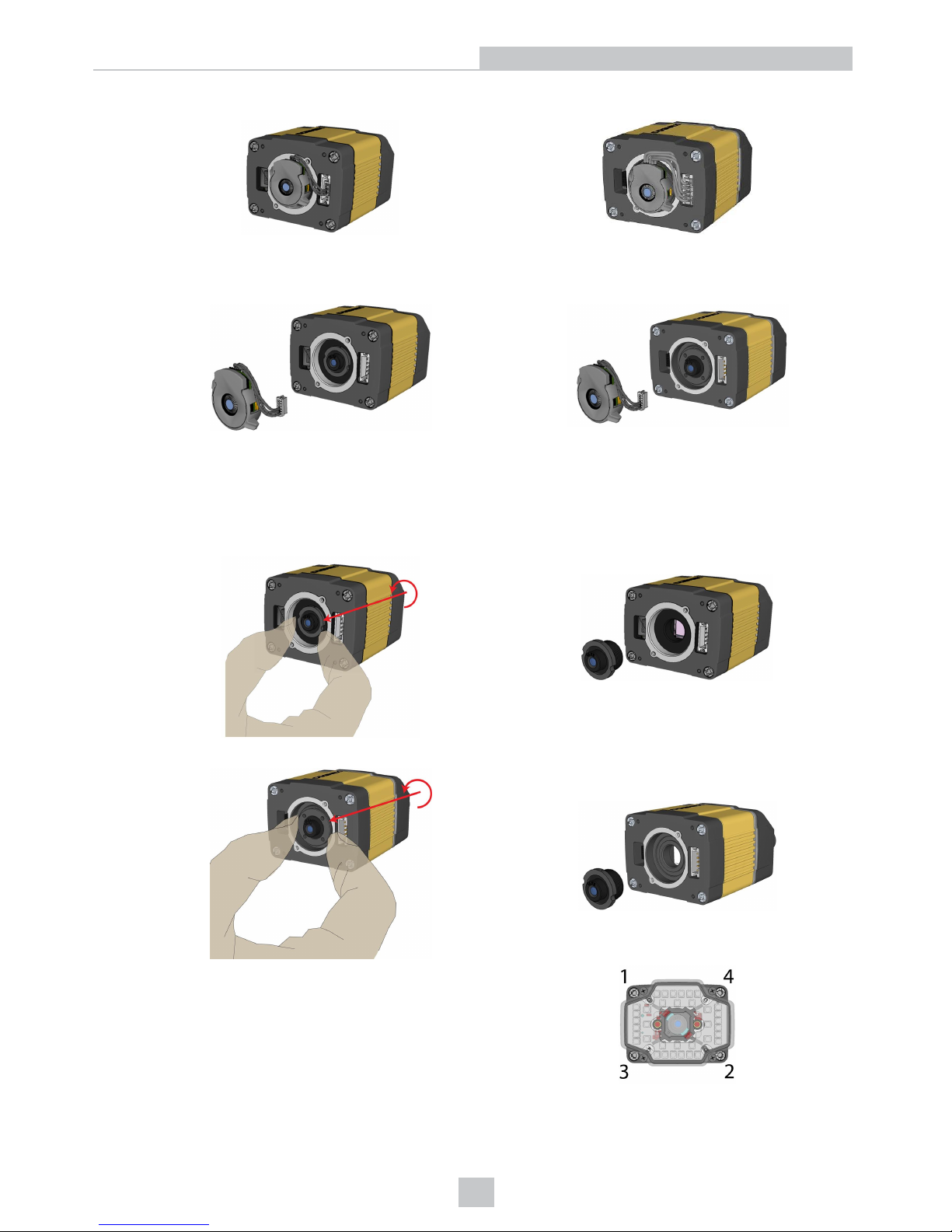
DataMan 300 DataMan 360
4. Loosen the lens locking ring and withdraw the module.
DataMan 300 DataMan 360
When reinstalling the module, observe the following precautions:
l Make sure that the liquid lens cable is not pinched, pulled or crimped during installation.
5. Loosen the locking ring and withdraw the lens.
DataMan 300
DataMan 360
When reattaching the front cover, tighten the screws in
the sequence shown below and observe a torque limit
of 9 N-cm (0.8 Lb-In).
26
Mechanical Information
Page 27
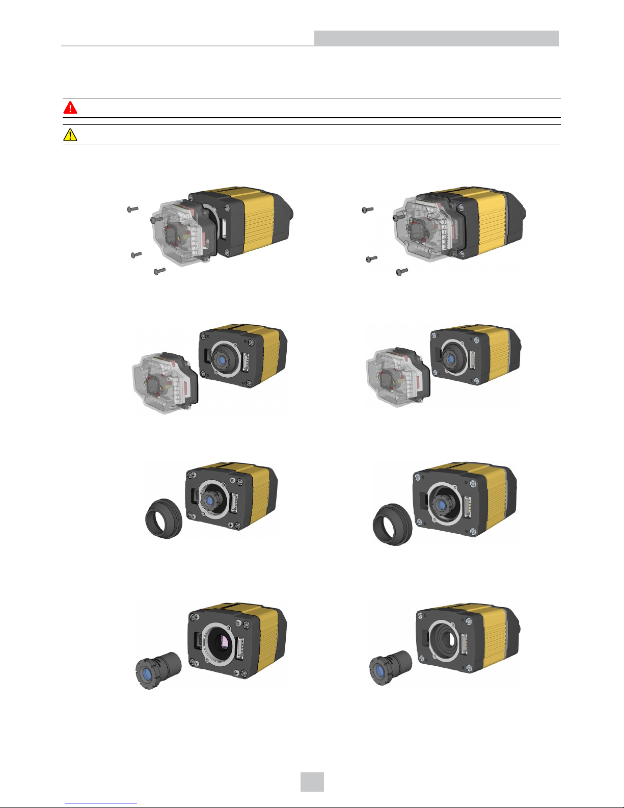
Replacing a 16 mm (SHD) Lens
To remove and replace a 16 mm (SHD) lens of a DataMan 300 or 360 series reader, perform the following steps:
WARNING: Disconnect the DataMan reader from power before continuing.
CAUTION: Do not leave the image sensor exposed to the environment.
1. Remove and retain the four screws at the corners of the front cover.
DataMan 300 DataMan 360
2. Remove the front cover.
DataMan 300 DataMan 360
3. Remove the rubber lens-locking cone from the lens.
DataMan 300 DataMan 360
4. Remove the lens.
DataMan 300 DataMan 360
When replacing the lens, observe the following precaution:
27
Mechanical Information
Page 28
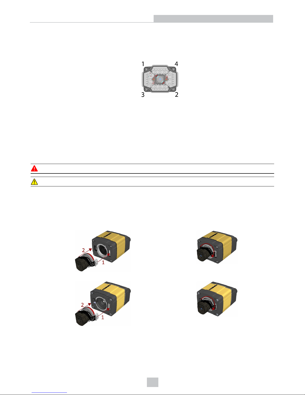
l Avoid rotating the lens when you insert it. Press the rubber lens-locking cone into the reader until it snaps
into place inside the C-mount threads and around the nose of the 16 mm lens.
When reattaching the front cover, tighten the screws in the sequence shown and observe a torque limit of 9 N-cm
(0.8 Lb-In).
Installing a 19 mm Liquid Lens
The possible hardware configurations using a 19 mm liquid lens with a DataMan 300 or 360 series reader are the
following:
l DM3xx-system + DM300-LENS-19LL + DM300-CMCOV-SH
l DM3xx-system + DM300-LENS-19LL + DM300-EXT + DM300-HPIL-RE
l DM3xx-system + DM300-LENS-19LL + DM300-EXT + DM300-HPIL-RE-P
To install a 19 mm liquid lens of a DataMan 300 or 360 series reader, perform the following steps:
WARNING: Disconnect the DataMan reader from power before continuing.
CAUTION: Do not leave the image sensor exposed to the environment.
With a DM300-CMCOV-SH Cover
1. First, attach the liquid lens cable to the unit.
2. Fix the lens by screwing in the knurled ring. Do not rotate the lens itself. Ensure that the cable and text are at the
12 o'clock position, as shown below.
DataMan 300
DataMan 360
28
Mechanical Information
Page 29
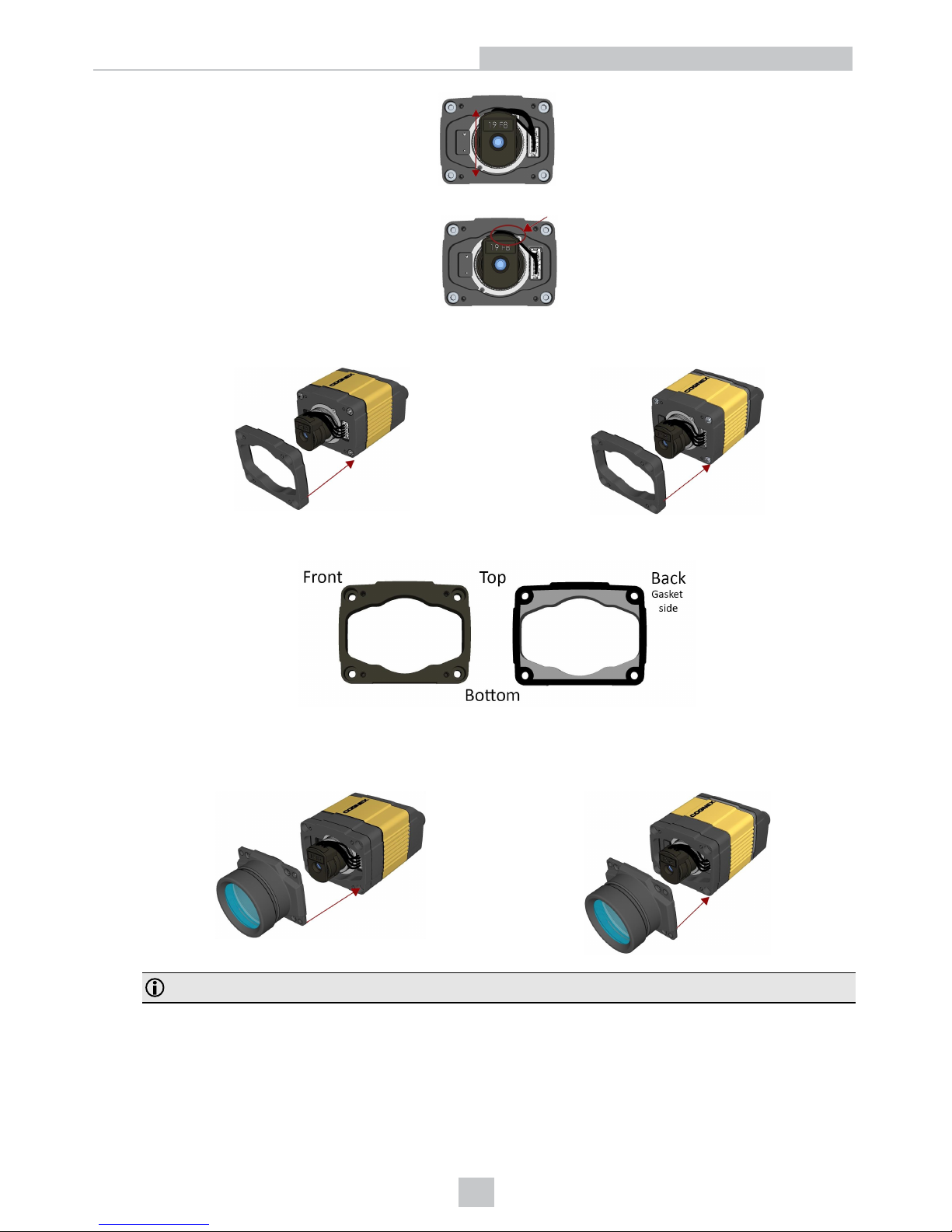
.
3. Push the wires into the space behind the lens.
4. Place the spacer over the front of the unit.
DataMan 300 DataMan 360
Ensure that the gasket side is toward and lines up with the unit.
5. Blow out the cover with compressed air.
6. Place the cover on the unit.
DataMan 300 DataMan 360
Note: Ensure that the top of each piece of the assembly lines up and the gasket does not stick out.
29
Mechanical Information
Page 30
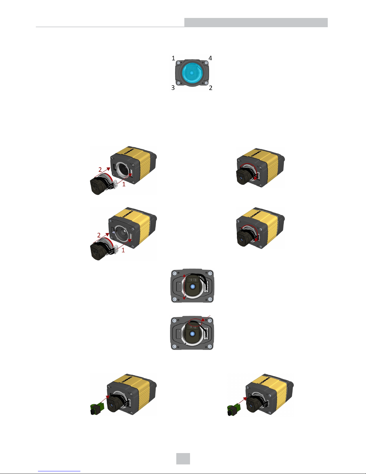
7. Screw in the four 196-1156R screws using a size 2.5 metric torque driver. Tighten the screws in the sequence
shown and observe a torque limit of 0.4 N-m.
With a DM300-HPIL-RE or DM300-HPIL-RE-P Cover
1. First, attach the liquid lens cable to the unit.
2. Fix the lens by screwing in the knurled ring. Do not rotate the lens itself. Ensure that the cable and text are at the
12 o'clock position, as shown below.
DataMan 300
DataMan 360
3. Push the wires into the space behind the lens.
4. Install the electrical extender.
DataMan 300 DataMan 360
30
Mechanical Information
Page 31
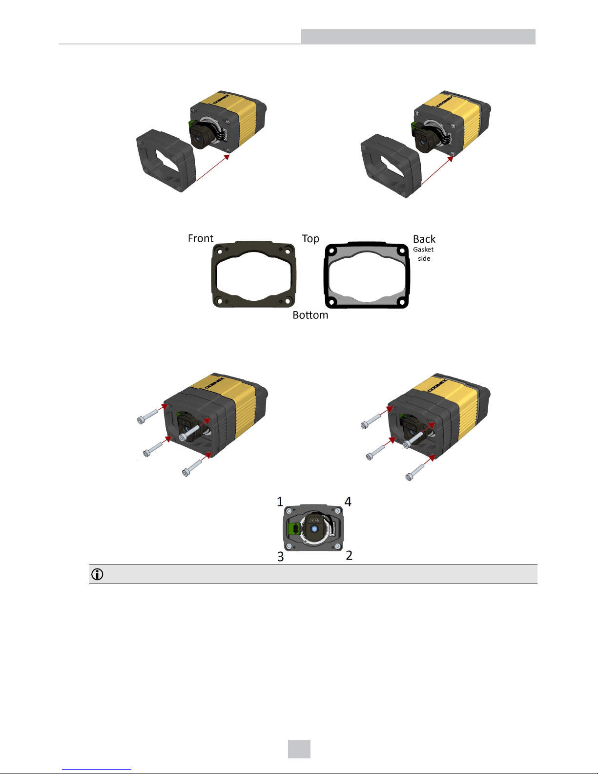
5. Place the spacer over the front of the unit.
DataMan 300 DataMan 360
Ensure that the gasket side is toward and lines up with the unit.
6. Screw in the four 196-1156R screws using a size 2.5 metric torque driver. Tighten the screws in the sequence
shown and observe a torque limit of 0.4 N-m.
DataMan 300 DataMan 360
Note: Ensure that the top of each piece of the assembly lines up and the gasket does not stick out.
31
Mechanical Information
Page 32
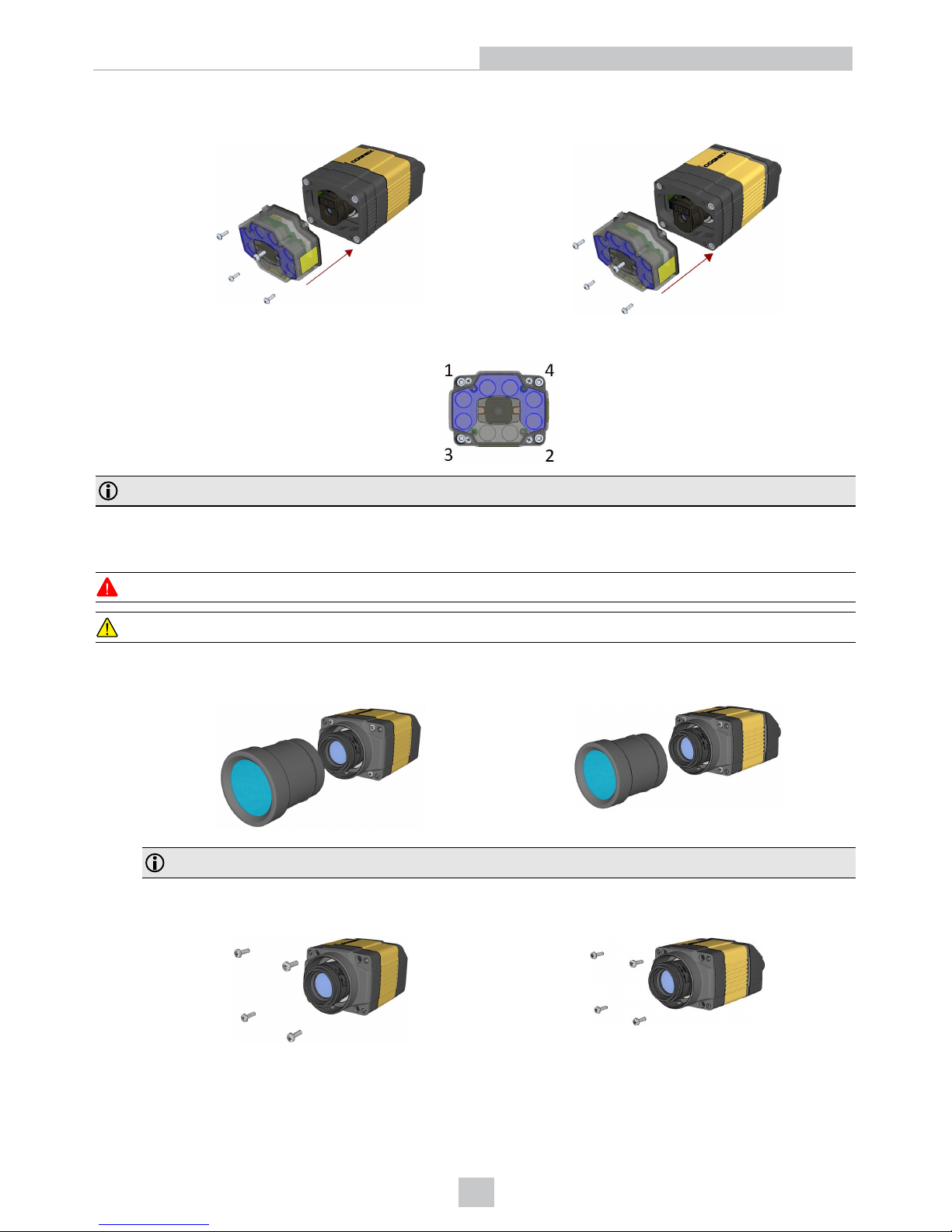
7. Place the cover on the unit.
DataMan 300 DataMan 360
8. Screw in the four screws. Tighten the screws in the sequence shown below and observe a torque limit of 9 N-cm.
Note: The protection foil must be removed from both light (outer) and lens (center) foils of the polarized cover.
Replacing a C-Mount Lens
To remove and replace a C-Mount lens of a DataMan 300 or 360 series reader, perform the following steps:
WARNING: Disconnect the DataMan reader from power before continuing.
CAUTION: Do not leave the image sensor exposed to the environment.
1. Remove the front cover.
DataMan 300 DataMan 360
Note: Do not unscrew the front-most part of the nose of the cover to avoid risking the glass lens falling out.
2. Remove the screws from the C-mount cover base.
DataMan 300 DataMan 360
32
Mechanical Information
Page 33
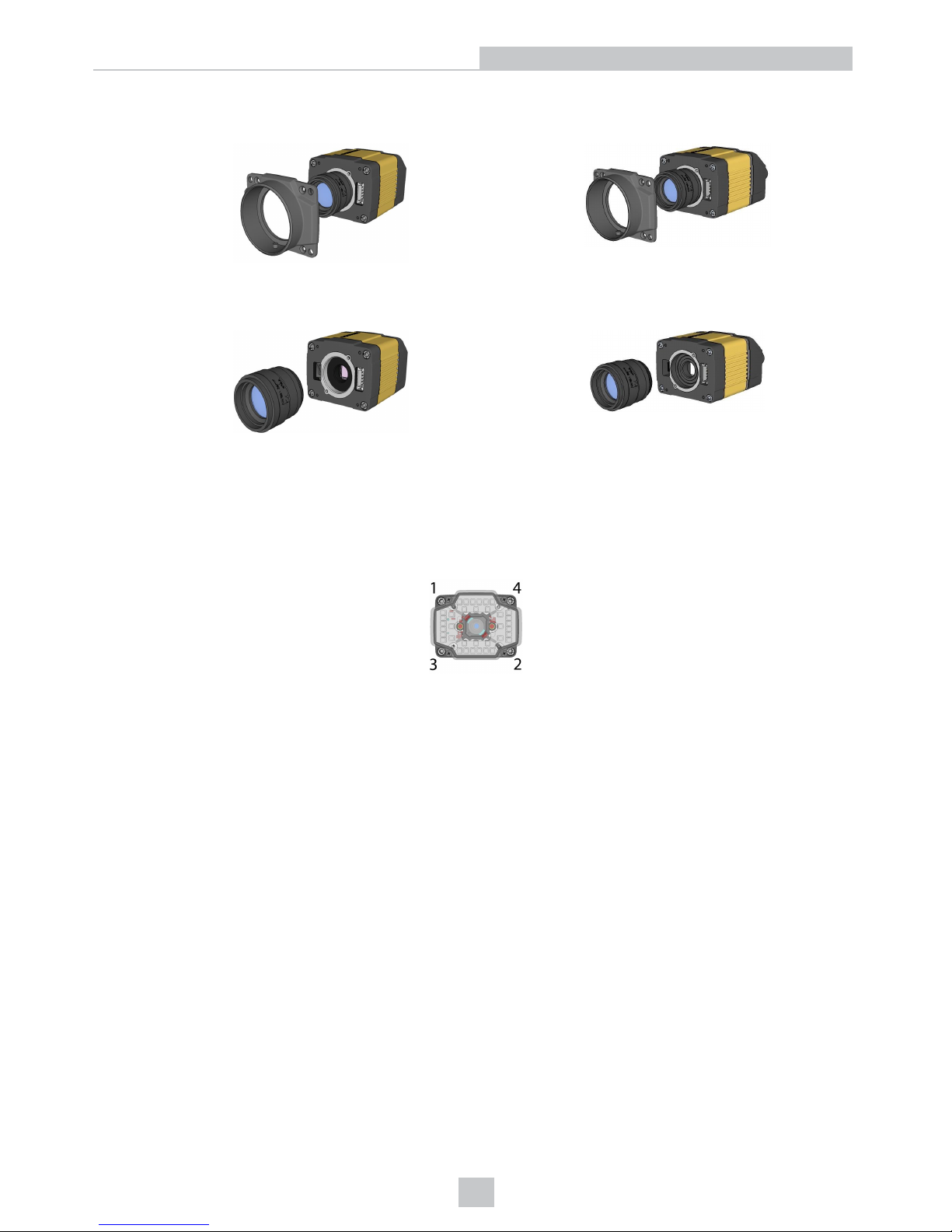
3. Remove the C-Mount cover base.
DataMan 300 DataMan 360
4. Remove the lens.
DataMan 300 DataMan 360
When replacing the lens, observe the following precaution:
l When you attach the front cover, align the peg on the reader and the slot on the cover so that the cover locks in
place.
When reattaching the C-mount cover base, tighten the screws in the sequence shown and observe a torque limit of 9 Ncm (0.8 Lb-In).
33
Mechanical Information
Page 34

DataMan 503 Service Procedures
Replacing a C, S, or CS-Mount Lens
To remove and replace a CS-Mount lens of a DataMan 503 reader, perform the following steps:
WARNING: Disconnect the DataMan reader from power before continuing.
CAUTION: Do not leave the image sensor exposed to the environment.
1. Remove the front cover.
2. Unscrew the lens.
3. Screw in the new lens.
4. Reattach the cover.
When replacing the lens, observe the following precaution:
l When reattaching the front cover, make sure that the peg on the reader and the slot on the cover are properly
aligned.
34
Mechanical Information
Page 35

Mounting Requirements
The DataMan 150, 260, 300, 360 and 503 series readers provide four threaded attachment points, located as shown in
the previous sections:
l DataMan 70 Series Reader Dimensions
l DataMan 150 Series Reader Dimensions
l DataMan 260 Series Reader Dimensions
l DataMan 300 Series Reader Dimensions
l DataMan 360 Series Reader Dimensions
l DataMan 503 Reader Dimensions
The attachment points have the following characteristics:
l M3 thread
l 5 mm thread depth
l 9 N-cm (0.8 Lb-In) maximum torque
CAUTION: Use all four attachment points when mounting your DataMan reader.
35
Mechanical Information
Page 36
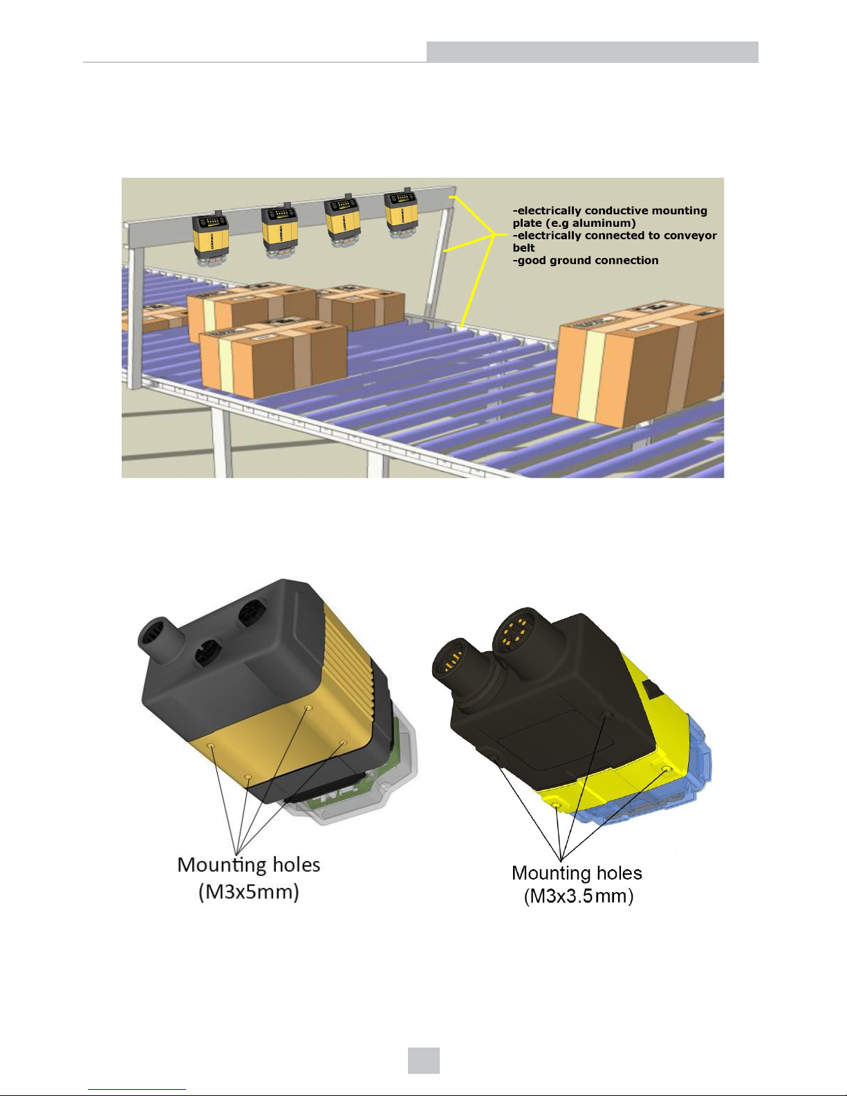
Grounding
If you want to mount a DataMan fixed mount reader to a bracket or a plate, make sure that those parts make a proper
connection to ground (PE). Cognex recommends that you use lock-washers between the mounting screws and the
bracket to ensure permanent ground conductivity.
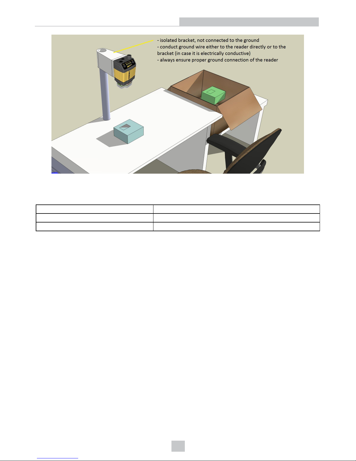
If you want to mount your reader to an electrically isolated bracket, the reader needs to be individually grounded.
For this purpose, Cognex recommends that you connect at least one of the 4 mounting holes on the bottom of the device
with a minimum 22 gauge grounding wire to system ground (PE). Use lock-washers to ensure a permanent and robust
connection.
36
Mechanical Information
Page 37
Thermal and Environmental Requirements
See the following table for thermal and environmental requirements:
Operating temperature 0 ºC — 40 ºC (32 ºF — 104 ºF)
Storage temperature -10 ºC — 60 ºC (-14 ºF — 140 ºF)
Maximum humidity 95% (non-condensing)
DataMan 50, 150, 260, 300, 360 and 503 IP Rating
The DataMan 50, 503, and the DataMan 150, 260, 300 and 360 series readers provide IP65 protection against dust and
water intrusion. In order to meet this rating, the following conditions must be met:
l All connectors must have cables connected or be sealed with protective plugs.
l The reader front cover and lens cover must be correctly installed.
l The requirements for temperature, vibration, and shock must be met.
DataMan 60 and 70 IP Rating
The DataMan 60 and 70 readers provide IP40 protection against dust and water intrusion. In order to meet this rating, the
following conditions must be met:
l All connectors must have cables connected or be sealed with protective plugs.
l The reader front cover and lens cover must be correctly installed.
l The requirements for temperature, vibration, and shock must be met.
37
Mechanical Information
Page 38
Electrical Information
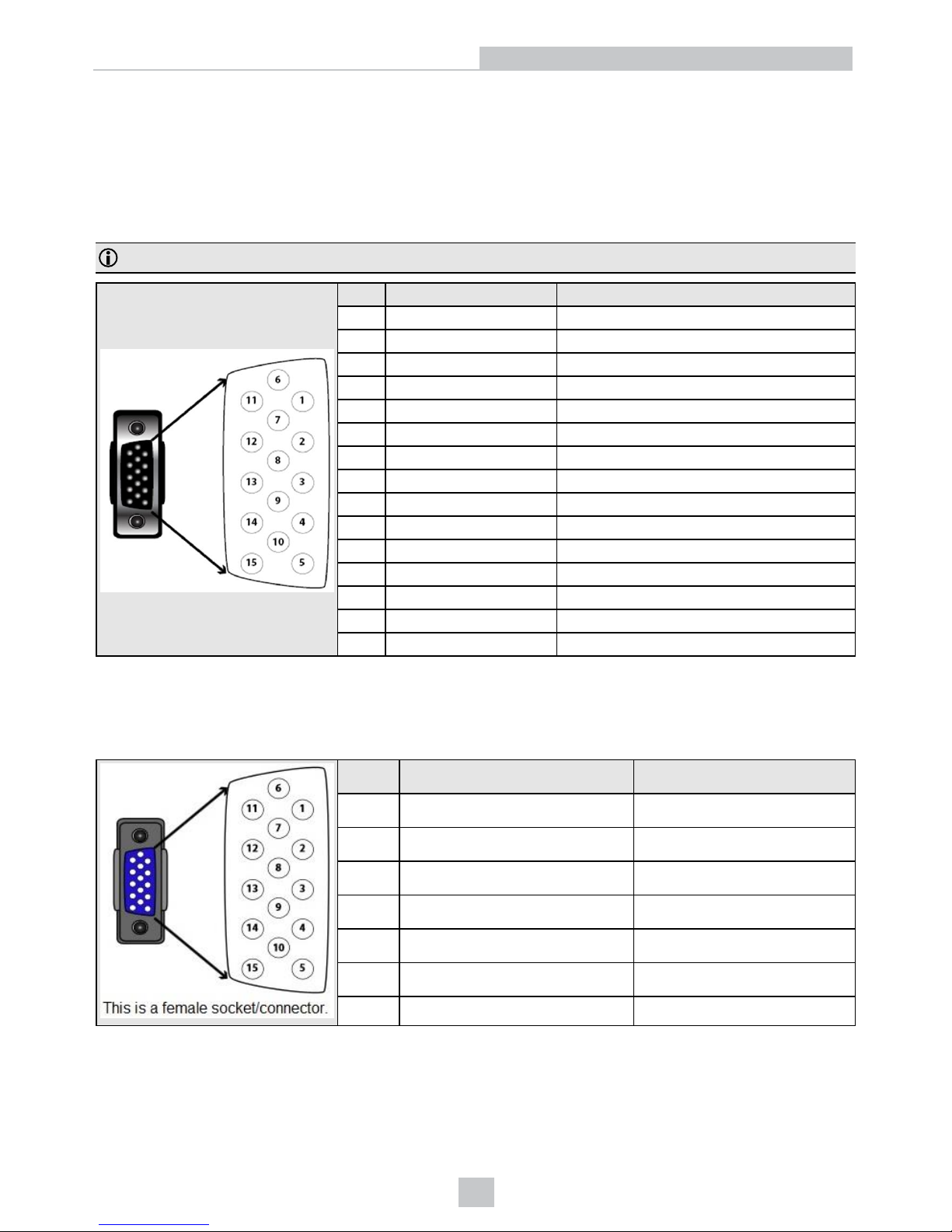
DataMan 50 and 60 Discrete I/O Connector
The I/O cable provides access to trigger and high-speed outputs. Unused wires can be clipped short or tied back using a
tie made of non-conductive material. For RS-232, use the Power Supply return path for ground.
Note: GND (Pin 4) is connected to the reader housing, cable shield, and DB15 shell.
PIN Color Signal
1 Brown Reserved
2 Green TxD
3 Green/Black RxD
4 Red & Red/Black GND
5 Brown/White DC+ (system power, 5-24 VDC)
6 Blue RTS
7 Blue/White Output-0
8 White Input-0
9 White/Black Input-1
10 Light Blue CTS
11 Light Blue/Black Output-1
12 Light Blue/Yellow Output-Common
13 Light Blue/Green Output-Strobe
14 Yellow Reserved
15 Yellow/Black Reserved
DataMan 50 and 60 USB & Flying Leads I/O Cable
You can connect a cable with USB & flying leads to the cable that is attached to the device. The following table shows
the pinout and color description of the flying leads.
PIN Color Signal
4 Black GND
7 Blue/White Output-0
8 White Input-0
9 White/Black Input-1
11 Light Blue/Black Output-1
12 Light Blue/Yellow Output-Common
13 Light Blue/Green Output-Strobe
38
Electrical Information
Page 39
DataMan 50 and 60 RS-232 & Flying Leads I/O Cable
You can connect a cable with RS-232 & flying leads to the cable that is attached to the device. The following table shows
the pinout and color description of the flying leads.
PIN Color Signal
4 Black GND
5 Brown/White VDC
7 Blue/White Output-0
8 White Input-0
9 White/Black Input-1
11 Light Blue/Black Output-1
12 Light Blue/Yellow Output-Common
13 Light Blue/Green Output-Strobe
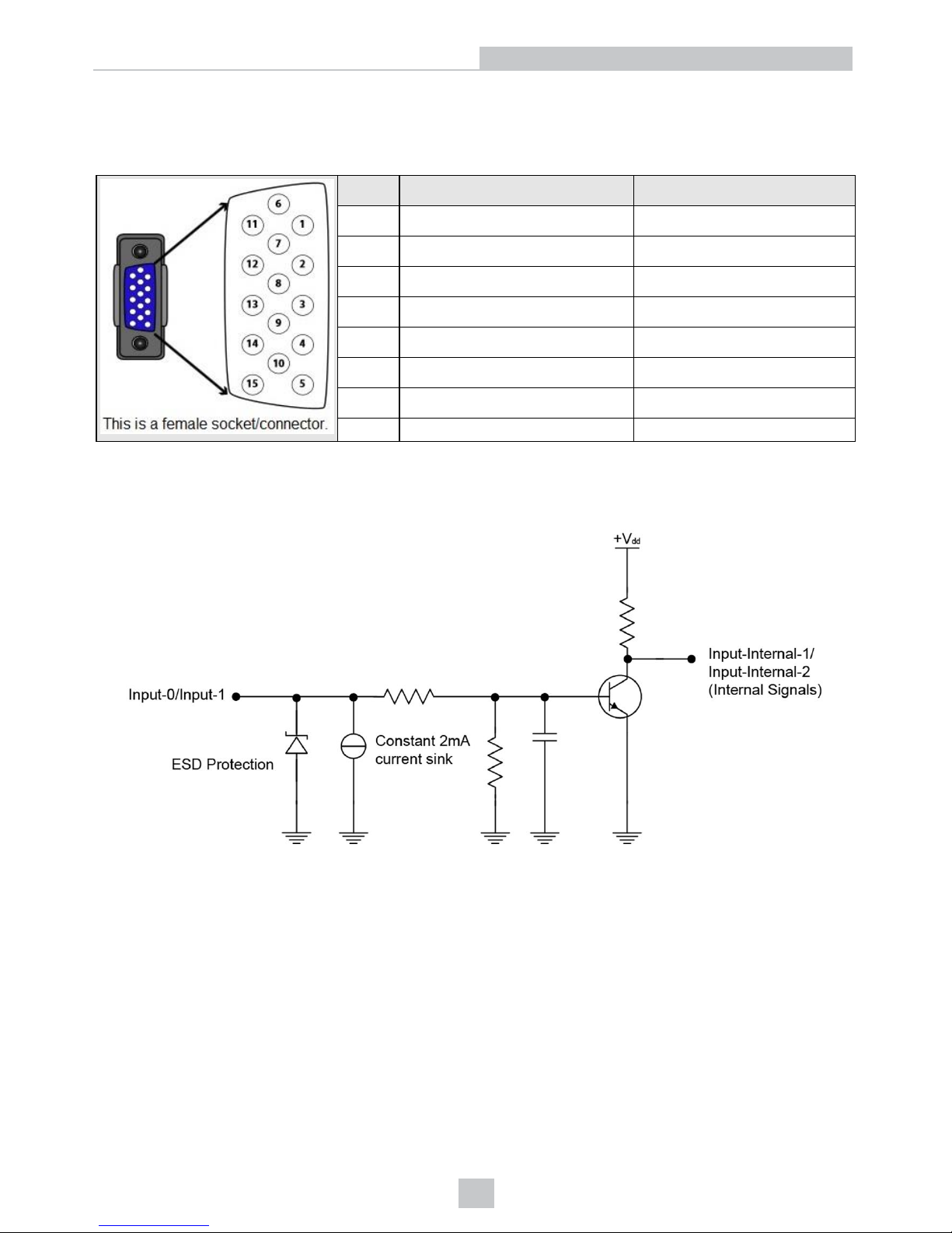
DataMan 50 and 60 Digital Input Lines
Inputs are not galvanic isolated but need to be referenced to ground.
39
Electrical Information
Page 40
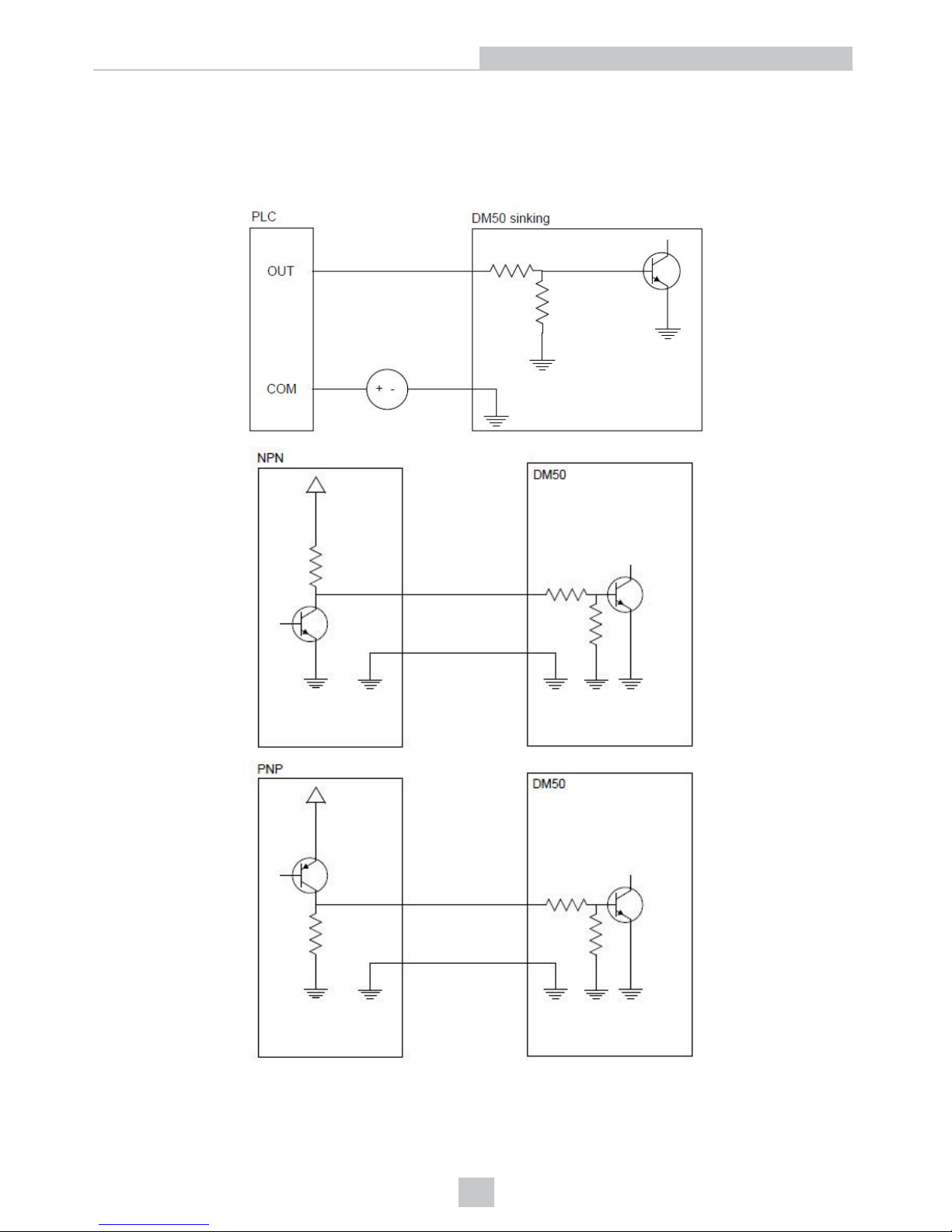
DataMan 50 and 60 External Wiring Examples: Digital Input
Lines
The following figures show external wiring examples for digital input lines for the DataMan 50. The DataMan 60 has the
same characteristics.
40
Electrical Information
Page 41
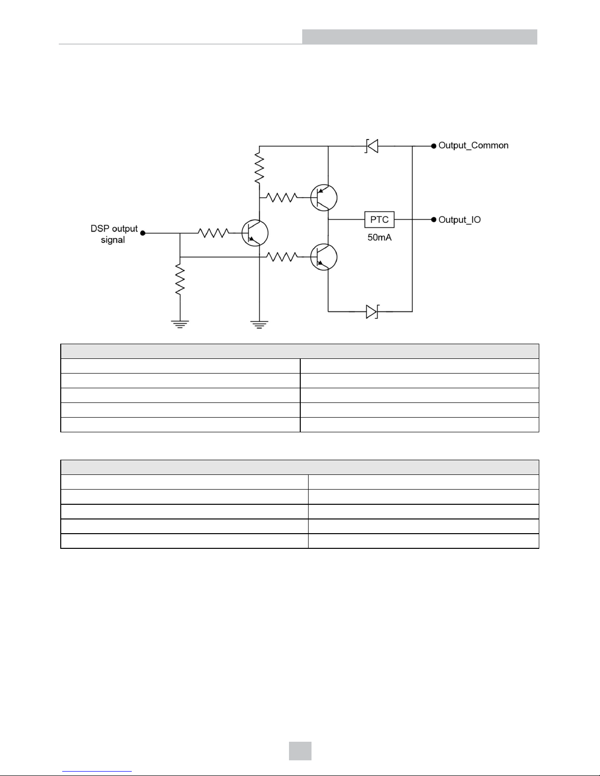
DataMan 50 and 60 Digital Output Lines
The digital outputs can be used as either NPN (pull-down) or PNP (pull-up) lines. For NPN lines, the external load
should be connected between the output and the positive supply voltage (<26V). The outputs pull down to less than 3V
when ON, which causes current to flow through the load. When the outputs are OFF, no current flows through the load.
Outputs are not galvanic isolated but need to be referenced to ground.
NPN (pull down) output type characteristics
Applied voltage 26 VDC or less
Residual voltage 0.85V or less
Maximum sink current 25mA
Short-circuit current 100mA or less
Short-circuit protection multifuse – 50mA
PNP (pull up) output type characteristics
Applied voltage 26 VDC or less
Residual voltage 0.8V or less
Maximum sink current 25mA
Short-circuit current 50mA or less
Short-circuit protection multifuse – 50mA
41
Electrical Information
Page 42
42
Electrical Information
Page 43
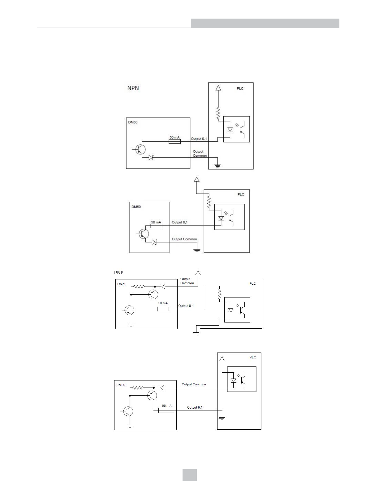
DataMan 50 and 60 External Wiring Examples: Digital Output
Lines
The following figures show external wiring examples for digital input lines for the DataMan 50. The DataMan 60 has the
same characteristics.
43
Electrical Information
Page 44
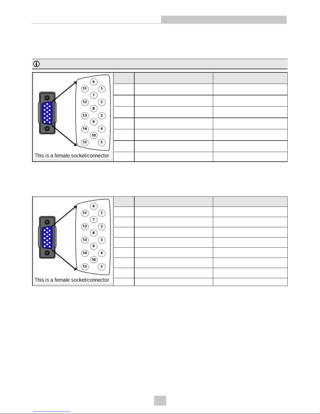
DataMan 70 and 150 Discrete I/O Connector
You can connect a cable with USB & flying leads (DM-USBIO-00) to the cable that is attached to the device. The
following table shows the pinout and color description of the flying leads.
Note: GND (Pin 4) is connected to the reader housing, cable shield, and DB15 shell.
PIN Color Signal
4 Black GND
7 Blue/White Output-0
8 White Input-0
9 White/Black Input-1
11 Light Blue/Black Output-1
12 Light Blue/Yellow Output-Common
13 Light Blue/Green Input-Common
DataMan 70 and 150 RS-232 Cable
You can connect a cable with RS-232 & flying leads (DM-RS232IO-00) to the cable that is attached to the device. The
following table shows the pinout and color description of the flying leads.
PIN Color Signal
4 Black GND
5 Brown/White VDC
7 Blue/White Output-0
8 White Input-0
9 White/Black Input-1
11 Light Blue/Black Output-1
12 Light Blue/Yellow Output-Common
13 Light Blue/Green Input-Common
44
Electrical Information
Page 45
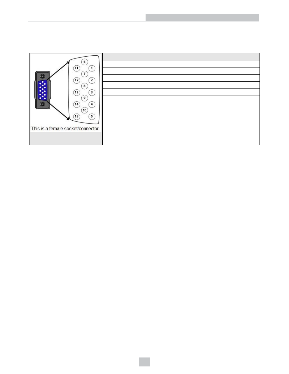
DataMan 150 Flying Leads Cable
You can connect a cable with flying leads (DM50-PWRIO-05) to the cable that is attached to the device. The following
table shows the pinout and color description of the flying leads.
PIN Color Signal
2 Green TxD
3 Green/Black RxD
4 Red GND
5 Brown/White DC+(system power, 5-24 VDC)
6 Blue RTS
7 Blue/White Output-0
8 White Input-0
9 White/Black Input-1
10 Light Blue CTS
11 Light Blue/Black Output-1
12 Light Blue/Yellow Output-Common
13 Light Blue/Green Input-Common
45
Electrical Information
Page 46
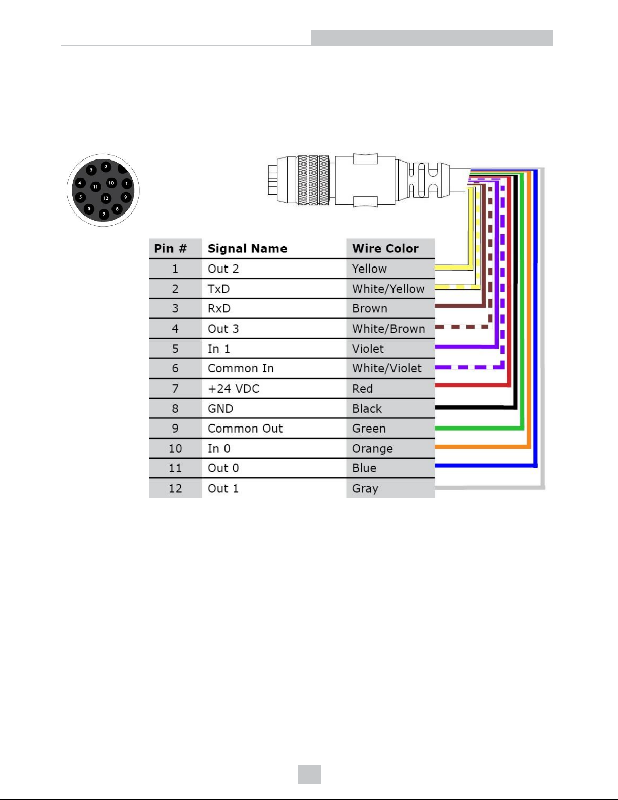
DataMan 260 Discrete I/O Connector
The I/O breakout cable (CCBL-05-01) provides access to trigger and high-speed outputs. Unused wires can be clipped
short or tied back using a tie made of non-conductive material. For RS-232, use the Power Supply return path for ground.
The drawing on the left shows the plug on the device.
Signal: 24 VDC Ethernet Model
46
Electrical Information
Page 47
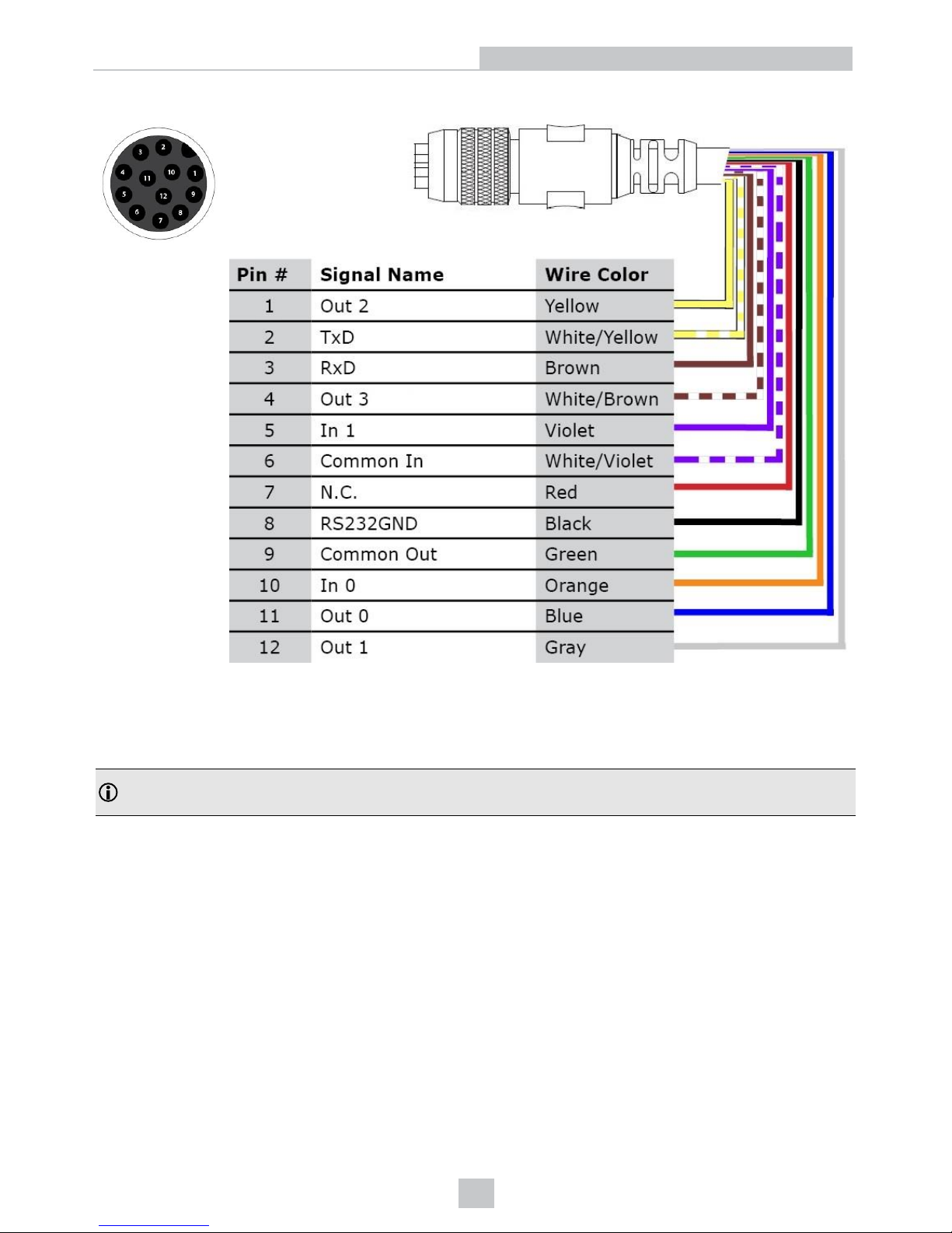
Signal: PoE Ethernet Model
DataMan 260 Ethernet Cable
The Ethernet cable (CCB-84901-2001-05) provides Ethernet connection for network communications. The Ethernet
cable can be connected to a single device or provide connections to multiple devices via a network switch or router.
Note: Cables are sold separately.The wiring for this cable follows standard industrial Ethernet M12 specifications.
This differs from the 568B standard.
47
Electrical Information
Page 48
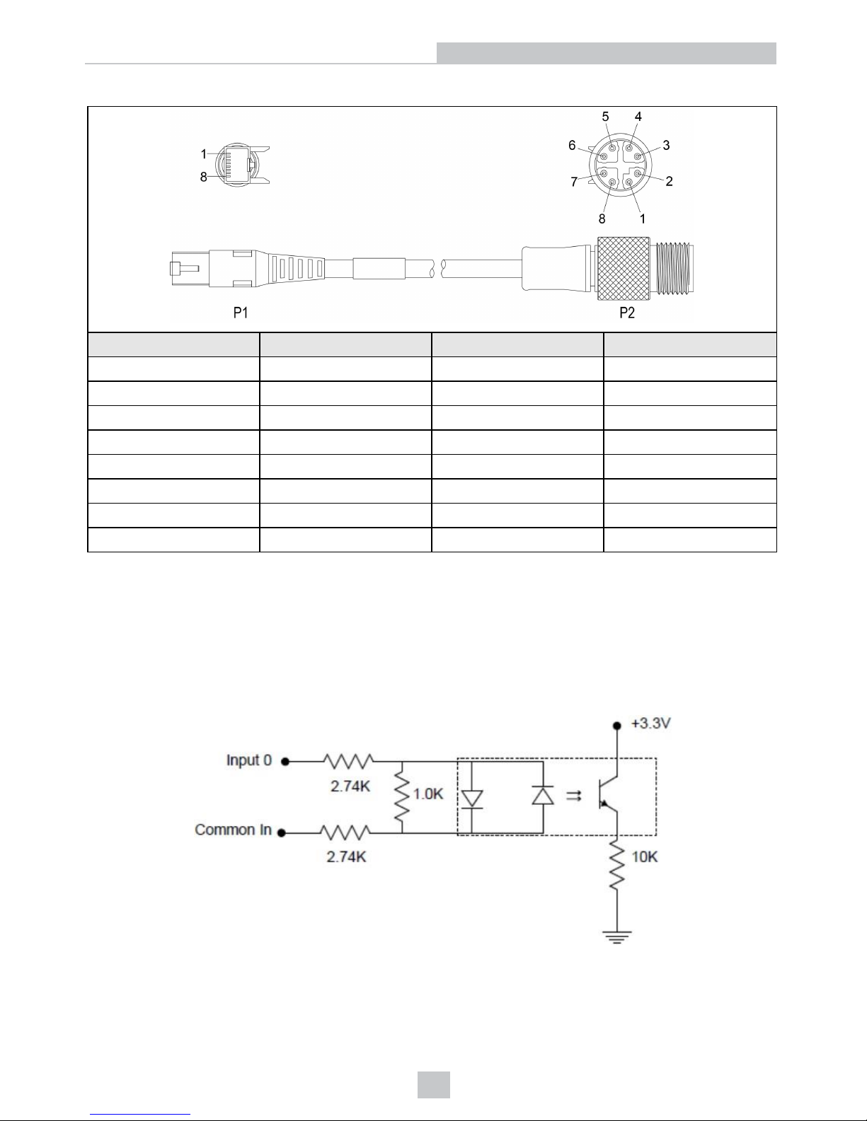
X-coded to RJ45 Cable
P1 Pin Number Wire Color Signal Name P2 Pin Number
1 White/Orange TxRx A + 1
2 Orange TxRx A - 2
3 White/Green TxRx B + 3
4 Blue TxRx C + 8
5 White/Blue TxRx C - 7
6 Green TxRx B - 4
7 White/Brown TxRx D + 5
8 Brown TxRx D - 6
DataMan 260 Acquisition Triggering
The acquisition trigger input on the reader is opto-isolated.
To trigger from an NPN (pull-down) type photo-detector or PLC output, connect In 0 to +24V and connect Common In to
the output of the detector. When the output turns on, it pulls Common In down to 0V, turning the opto-coupler on.
To trigger from a PNP (pull-up) photo-detector or PLC output, connect In 0 to the output of the detector and connect
Common In to 0V. When the output turns on, it pulls In 0 up to 24V, turning the opto-coupler ON.
28V maximum across input pins - Transition approximately 12V (Min).
48
Electrical Information
Page 49
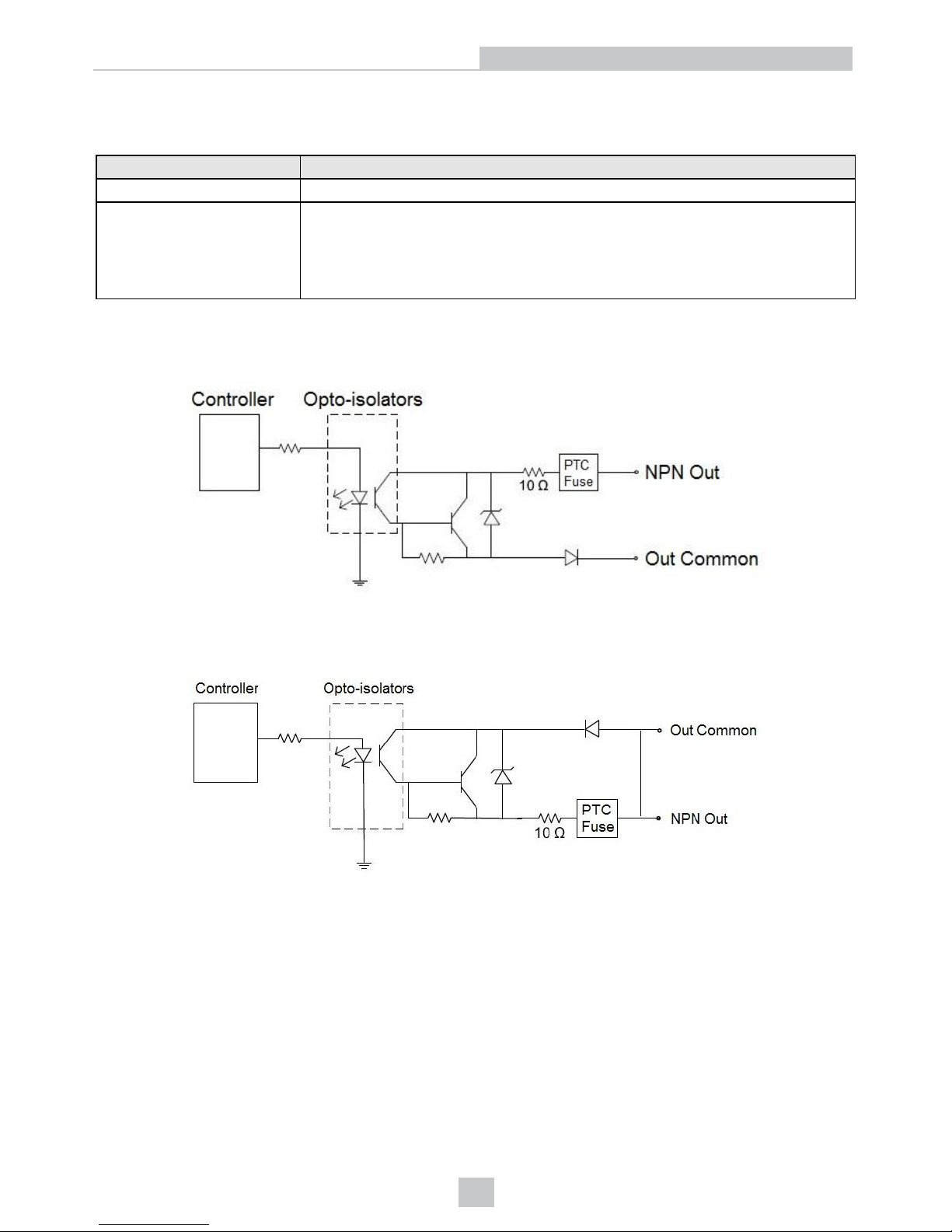
DataMan 260 High-Speed Output Lines
The high-speed outputs can be used as either NPN (pull-down) or PNP (pull-up) lines.
Specification Description
Voltage 28V maximum through external load
Current
50mA maximum sink current
OFF state leakage current 100µA
External load resistance 240 Ohms to 10K Ohms
Each line rated at a maximum 50mA, protected against over-current, short circuits and
transients from switching inductive loads. High current inductive loads require external
protection diode.
For NPN lines, the external load should be connected between the output and the positive supply voltage (<28V). The
outputs pull down to less than 3VDC when ON, which causes current to flow through the load. When the outputs are
OFF, no current flows through the load.
For PNP lines, the external load should be connected between the output and the negative supply voltage (0VDC).
When connected to a 24VDC power supply, the outputs pull up greater than 21VDC when ON, and current flows through
the load. When the outputs are OFF, no current flows through the load.
DataMan 260 High-Speed Output Wiring
To connect to an NPN-compatible PLC input, connect Output 0 or Output 1 directly to the PLC input. When enabled, the
output pulls the PLC input down to less than 3V.
49
Electrical Information
Page 50
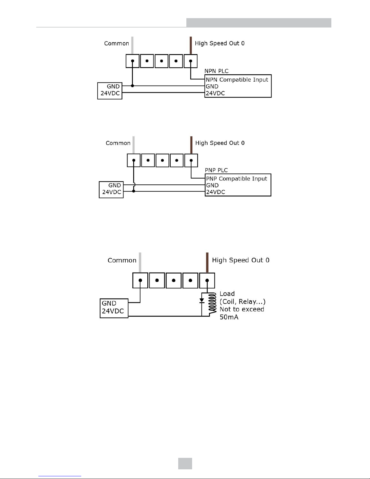
To connect to a PNP-compatible PLC input, connect Output 0 or Output 1 directly to the PLC input. When enabled, the
output pulls the PLC input up to greater than 21VDC.
To connect the high-speed outputs to a relay, LED or similar load, connect the negative side of the load to the output and
the positive side to +24VDC. When the output switches on, the negative side of the load is pulled down to less than 3V,
and 24 appears across the load. Use a protection diode for a large inductive load, with the anode connected to the
output and the cathode connected to +24VDC.
50
Electrical Information
Page 51
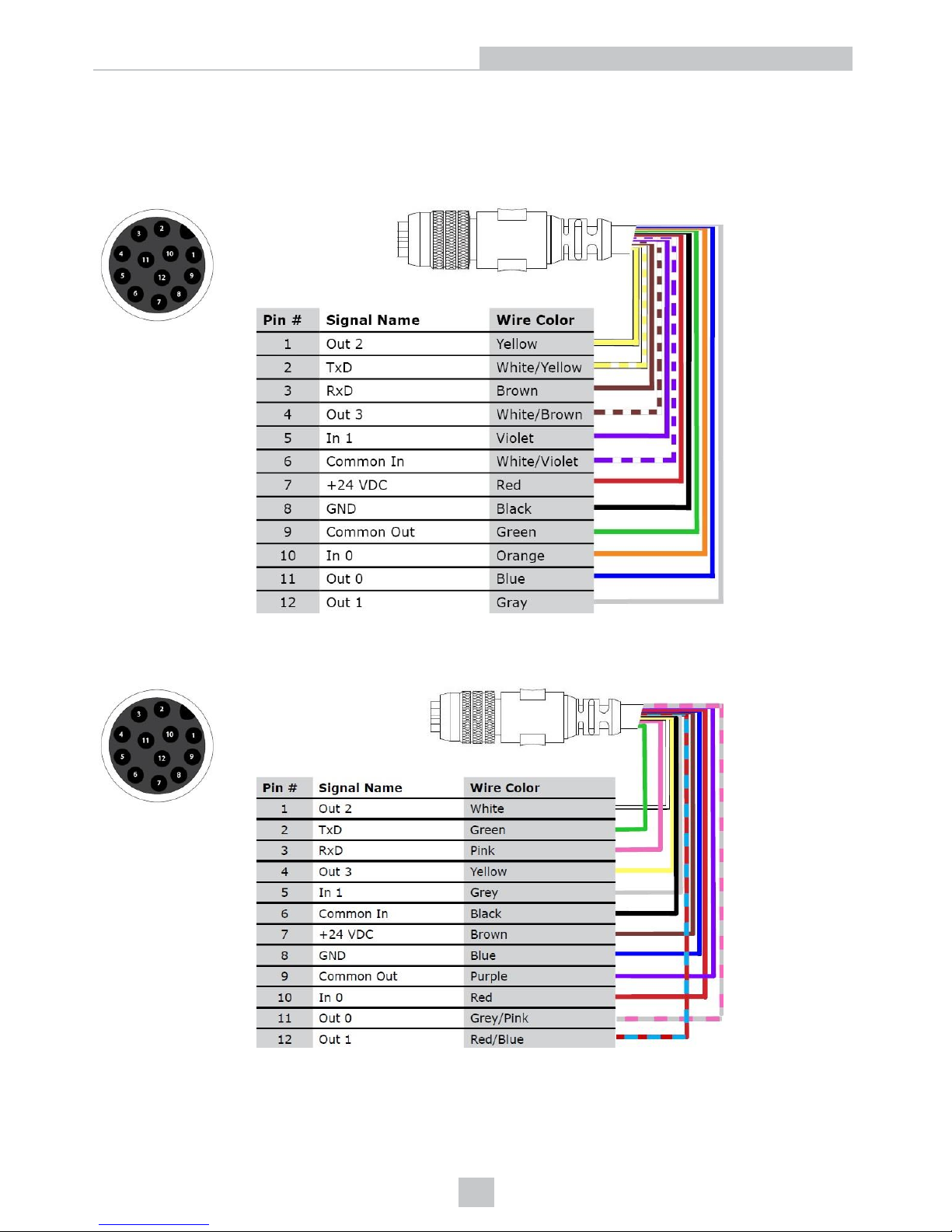
DataMan 300 and 360 Series Readers Discrete I/O Connector
The I/O cable (CCBL-05-01) provides access to trigger and high-speed outputs. Unused wires can be clipped short or
tied back using a tie made of non-conductive material. For RS-232, use the Power Supply return path for ground.
The drawing on the left shows the plug on the device.
The following figure shows the pin-out numbering on the device, and information about the I/O cable on the DataMan
300 or 360 series reader. This is the I/O cable with part number CCB-M12xM12Fy-xx.
51
Electrical Information
Page 52
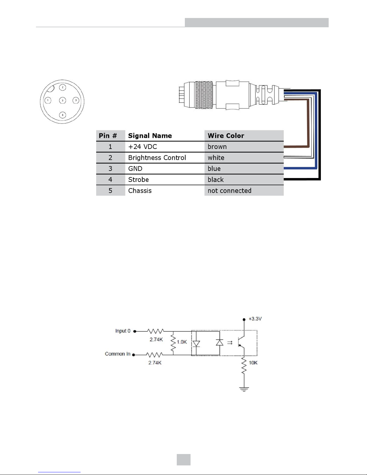
DataMan 300 and 360 Series Readers External Light Control
A 4-pin cable is provided for the external light control.
The drawing on the left shows the socket on the device. This socket does not work if the external light is connected to
one of the outputs on the breakout cable.
Current load: average: 500mA, peak: 1A (max. 100µs).
DataMan 300 and 360 Series Readers Power Requirements
For the DataMan 300 and 360 series readers, 24VDC power is provided through the I/O+RS232+24V cable. Maximum
power consumption is 5W (internal illumination) or 18W (internal and external lights).
DataMan 300 and 360 Series Readers Acquisition Triggering
The acquisition trigger input on the reader is opto-isolated.
To trigger from an NPN (pull-down) type photo-detector or PLC output, connect Common In to +24VDC and connect In to
the output of the detector. When the output turns on, it pulls In down to 0VDC, turning the opto-coupler on.
To trigger from an PNP (pull-up) photo-detector or PLC output, connect In 0 to the output of the detector and connect
Common In to 0VDC. When the output turns on, it pulls In 0 up to 24VDC, turning the opto-coupler ON.
26.4V maximum across input pins – Transition approximately 12V (Min).
DataMan 300 and 360 Series Readers High Speed Output Lines
The high-speed outputs can be used as either NPN (pull-down) or PNP (pull-up) lines.
52
Electrical Information
Page 53
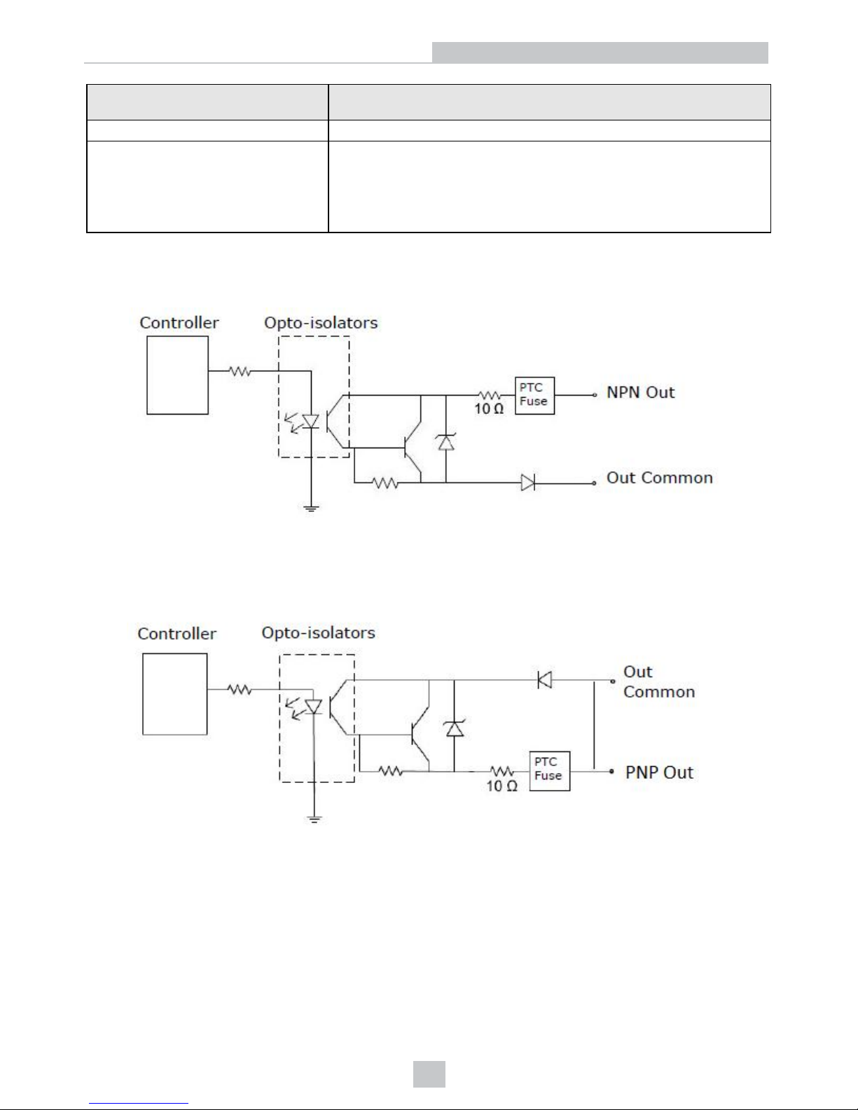
Specification DataMan 300 and 360 Series Readers and DataMan 503 Reader
Description
Voltage 26.4V maximum through external load
Current
50mA maximum sink current
OFF state leakage current 100µA
External load resistance 240 Ohms to 10K Ohms
Each line rated at a maximum 50mA, protected against over-current, short
circuits and transients from switching inductive loads. High current inductive
loads require external protection diode.
For NPN lines, the external load should be connected between the output and the positive supply voltage (<26.4VDC).
The outputs pull down to less than 3VDC when ON, which causes current to flow through the load. When the outputs are
OFF, no current flows through the load.
For PNP lines, the external load should be connected between the output and the negative supply voltage (0VDC).
When connected to a 24VDC power supply, the outputs pull up greater than 21VDC when ON, and current flows through
the load. When the outputs are OFF, no current flows through the load.
53
Electrical Information
Page 54
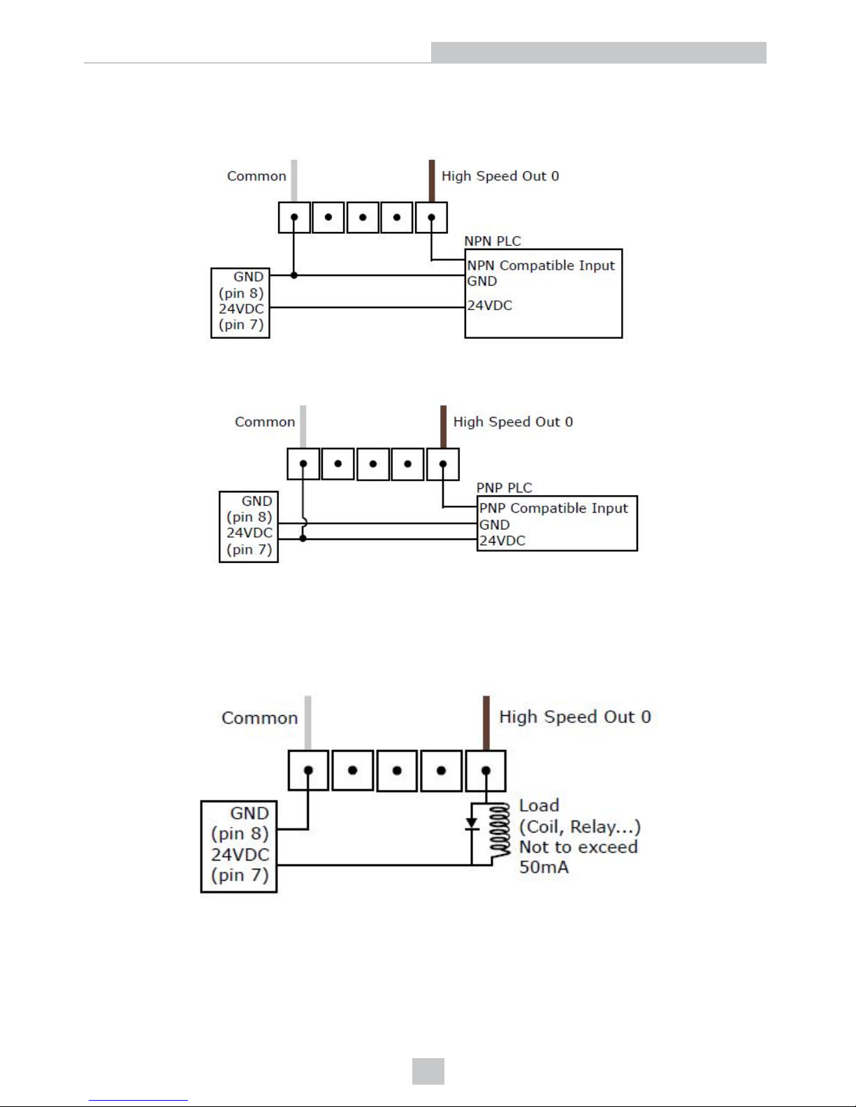
DataMan 300 and 360 Series Readers High Speed Output Wiring
To connect to an NPN-compatible PLC input, connect Output 0, Output 1, Output 2, or Output 3 directly to the PLC input.
When enabled, the output pulls the PLC input down to less than 3VDC.
To connect to a PNP-compatible PLC input, connect Output 0, Output 1, Output 2 or Output 3 directly to the PLC input.
When enabled, the output pulls the PLC input up to greater than 21VDC.
To connect the high-speed outputs to a relay, LED or similar load, connect the negative side of the load to the output and
the positive side to +24VDC. When the output switches on, the negative side of the load is pulled down to less than
3VDC, and 24 appears across the load. Use a protection diode for a large inductive load, with the anode connected to
the output and the cathode connected to +24VDC.
54
Electrical Information
Page 55
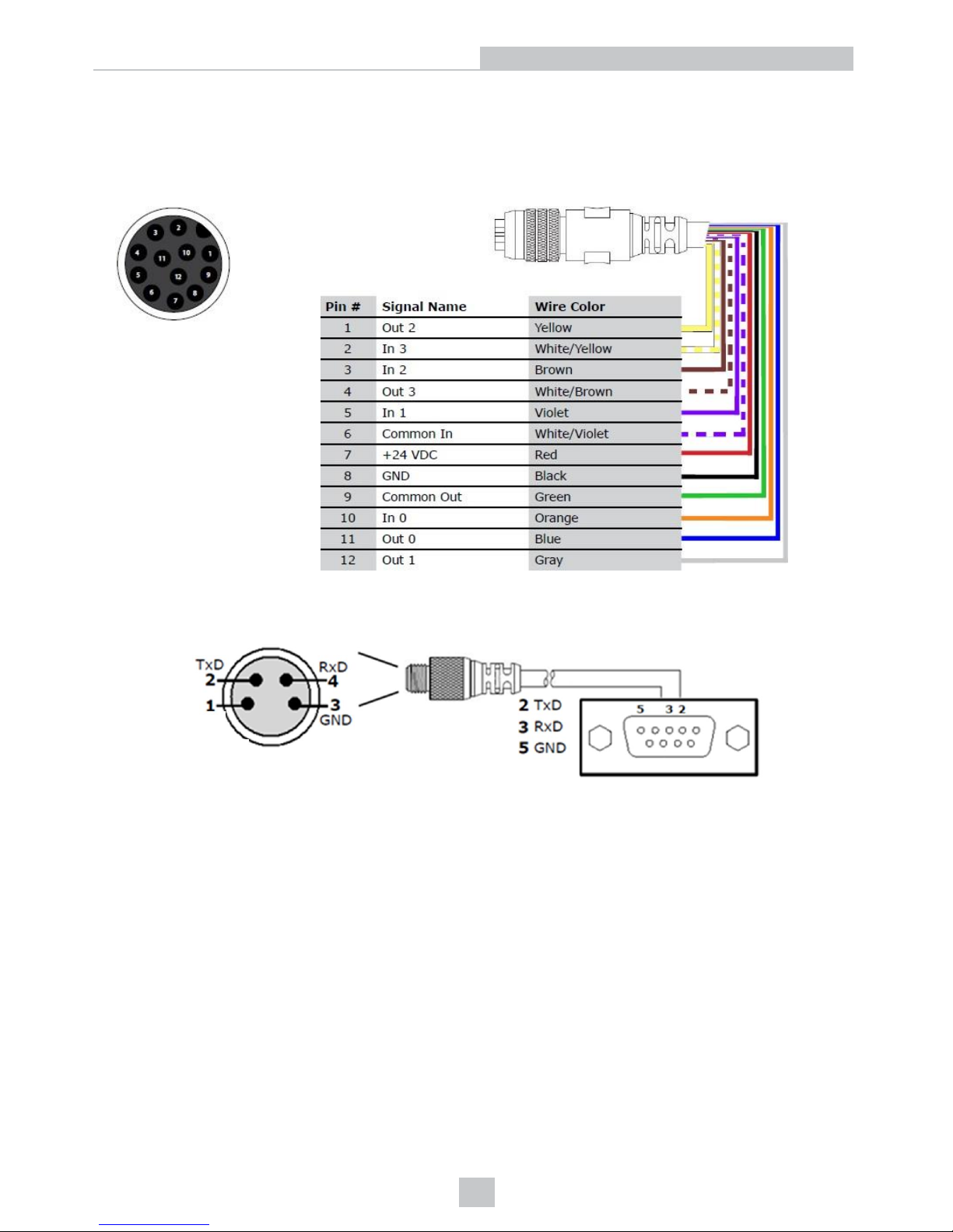
DataMan 503 Discrete I/O Connector
The Breakout cable provides access to trigger and high-speed outputs.Unused wires can be clipped short or tied back
using a tie made of non-conductive material.
The drawing on the left shows the plug on the device.
DataMan 503 RS-232 Serial Connector
55
Electrical Information
Page 56
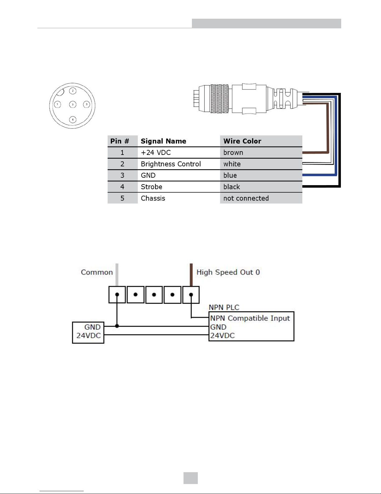
DataMan 503 External Light Control
A 4-pin cable is provided for the external light control.
The drawing on the left shows the socket on the device. This socket does not work if the external light is connected to
one of the outputs on the I/O cable.
Current load: average: 500mA, peak: 1A (max. 100µs).
DataMan 503 High-Speed Output Wiring
To connect to an NPN-compatible PLC input, connect Output 0, Output 1, Output 2, or Output 3 directly to the PLC input.
When enabled, the output pulls the PLC input down to less than 3VDC.
To connect to a PNP-compatible PLC input, connect Output 0 or Output 1 directly to the PLC input. When enabled, the
output pulls the PLC input up to greater than 21VDC.
56
Electrical Information
Page 57
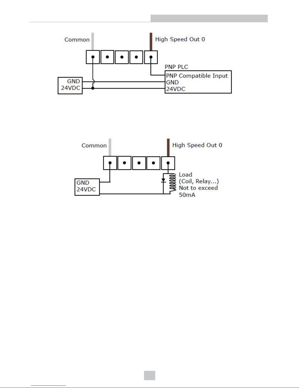
To connect the high-speed outputs to a relay, LED or similar load, connect the negative side of the load to the output and
the positive side to +24VDC. When the output switches on, the negative side of the load is pulled down to less than
3VDC, and 24 appears across the load. Use a protection diode for a large inductive load, with the anode connected to
the output and the cathode connected to +24VDC.
DataMan 503 Power Requirements
For the DataMan 503 readers, 24VDC power is provided through the I/O+RS232+24V cable. Maximum power
consumption is 13W (High-Power Lighting Module).
57
Electrical Information
Page 58
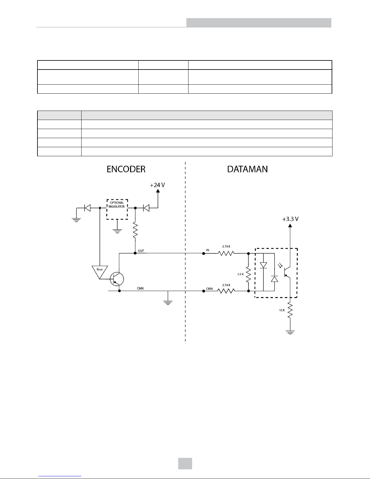
Connecting the Encoder to a DataMan
Encoder is supported on the following DataMan devices and with the following conditions:
DM50, DM60, DM70, DM150 unidirectional One input counts encoder ticks
DM260, DM300, DM503 bidirectional
• One input counts encoder ticks
• Second input for direction information
DM360 bidirectional 2 inputs for quadrature modulated signals
The encoder has four wires. The color coding of the wires is the following:
Wire Color Signal Name
Red +24VDC
Black common- can be connected to either +24VDC (NPN) or ground (PNP)
White the output connected to the input line of the DataMan reader
Bare ground
According to the speed of the line, set the number of pulses per revolution on the wheel by using the switches on the
encoder (for more information, see the encoder documentation). The number of pulses, however, must not exceed 150
Hz.
In the DataMan Setup Tool, configure the use of your DataMan reader with the encoder in the Pulse Encoder tab of the
System Settings pane.
58
Electrical Information
Page 59
Optics and Lighting
This section contains information about the image formation components of the DataMan 50, 60, 70, 150, 260, 503 and
DataMan 300 and 360 series readers.
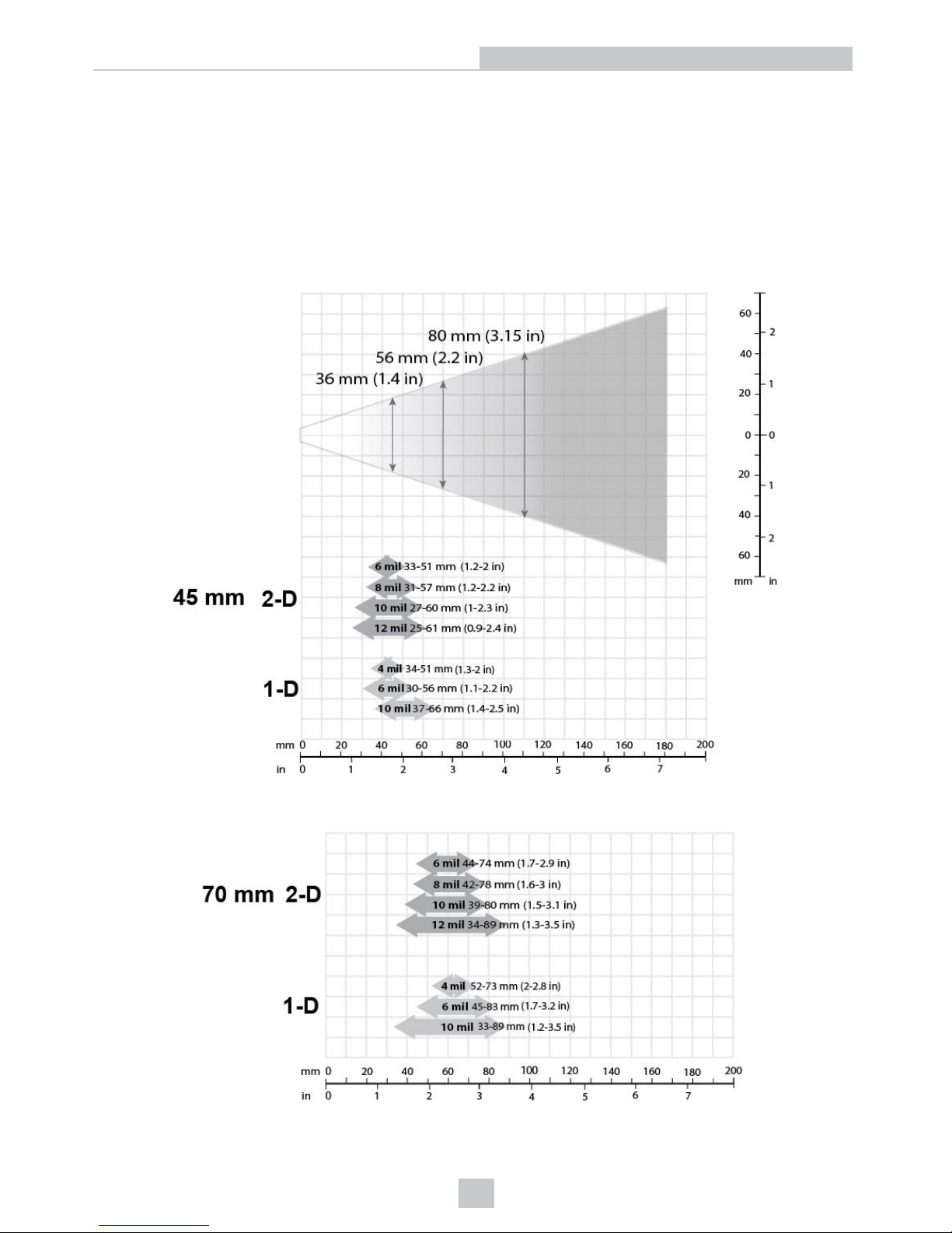
DataMan 50 and 60 Reading Distances and Field of View
The following chart shows the horizontal field of view for the DataMan 50 and 60 at a range of working distances,
together with the supported range of reading distances at 45 mm focus position.
This chart shows the supported range of reading distances at 70 mm focus position.
59
Optics and Lighting
Page 60
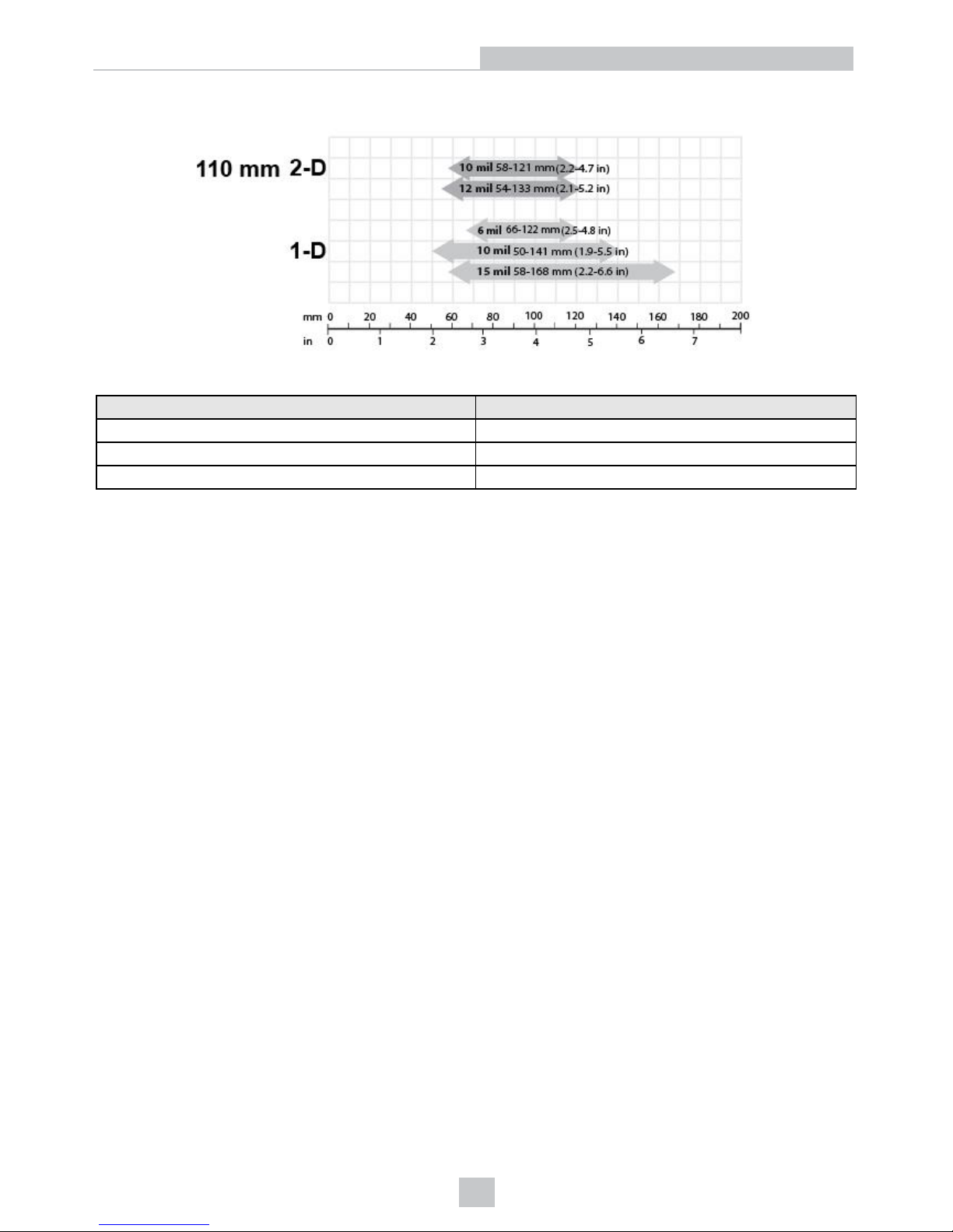
This chart shows the supported range of reading distances at 110 mm focus position.
The following table shows the Field of View widths at various distances.
Distances in mm DM50/DM60
45 36
70 56
110 80
60
Optics and Lighting
Page 61
DataMan 70, 150 and 260 Reading Distances and Field of View
DataMan 70, 150 and 260 Readers with a 6.2 mm Lens
Short Range (Focused to 105 mm)
The following tables show the field of view (FoV) widths of the 6.2 mm lens focused to 105 mm at various distances.
DM70, DM150 or DM260
Distances in mm 2D min. code 1D min. code
40 4 MIL 4 MIL
65 5 MIL 4 MIL
105 10 MIL 6 MIL
DM72, DM152 or DM262
Distances in mm 2D min. code 1D min. code
40 3 MIL 2 MIL
65 4 MIL 2 MIL
105 7 MIL 5 MIL
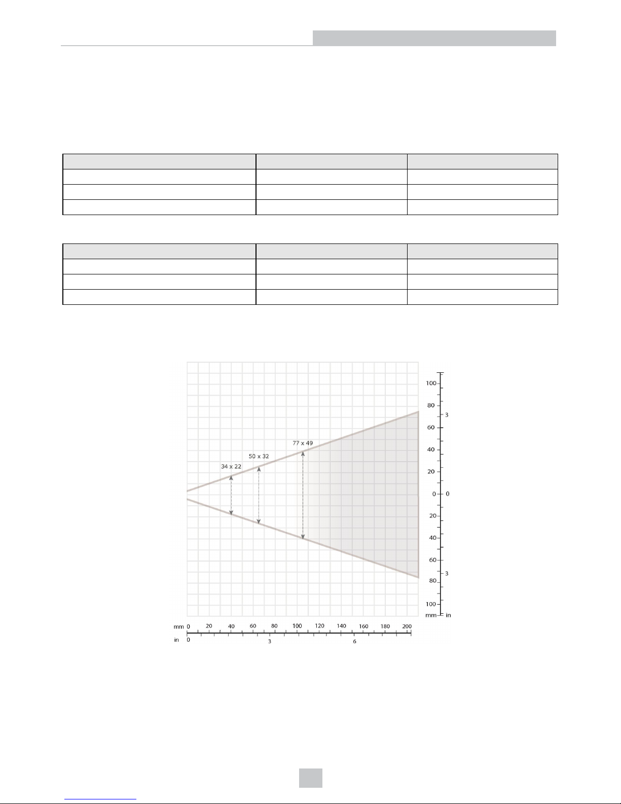
The following maps show the field of view (FoV) of the DataMan 70, DataMan 150 or DataMan 260 readers with a 6.2
mm lens. The horizontal and vertical field of view is shown for working distances of 40 mm, 65 mm and 105 mm.
DM70, DM150 or DM260 + 6.2 mm Lens
61
Optics and Lighting
Page 62
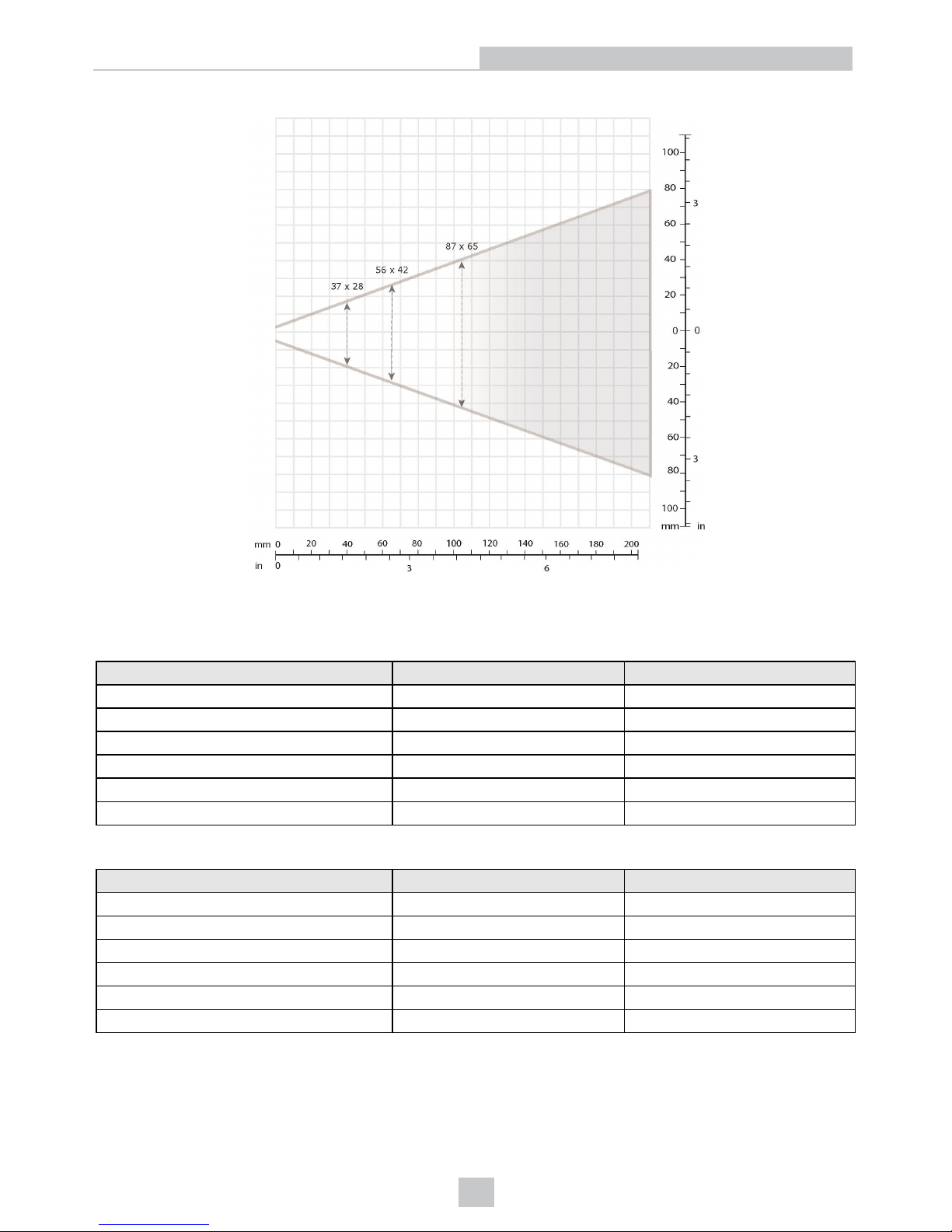
DM72, DM152 or DM262 + 6.2 mm Lens
Long Range (Focused to 190 mm)
The following tables show the FoV widths of the 6.2 mm lens focused to 190 mm at various distances.
DM150 or DM260
Distances in mm 2D min. code 1D min. code
150 12 MIL 6 MIL
190 15 MIL 10 MIL
225 18 MIL 10 MIL
375 30 MIL 15 MIL
500 35 MIL 20 MIL
1 m - 35MIL
DM152 or DM262
Distances in mm 2D min. code 1D min. code
150 12 MIL 5 MIL
190 10 MIL 6 MIL
225 15 MIL 6 MIL
375 20 MIL 10 MIL
500 25 MIL 15 MIL
1 m - 30MIL
62
Optics and Lighting
Page 63
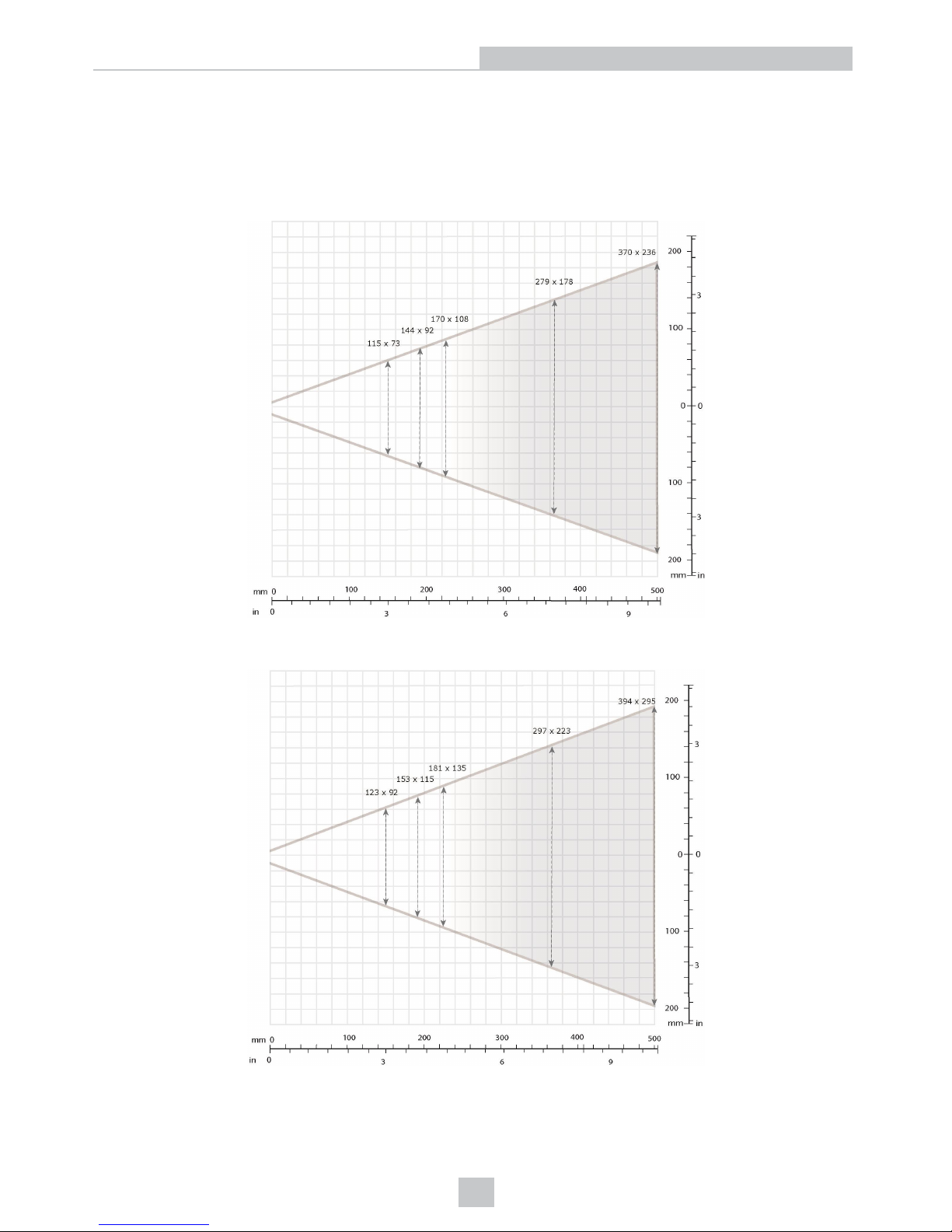
The following maps show the field of view (FoV) of the DataMan 150 or DataMan 260 readers with a 6.2 mm lens.
The horizontal and vertical field of view is shown for working distances of 150 mm, 190 mm, 225 mm, 375 mm and 500
mm.
DM150 or DM260 + 6.2 mm Lens
DM152 or DM262 + 6.2 mm Lens
63
Optics and Lighting
Page 64
DataMan 150 or DataMan 260 Readers with a 16 mm Lens
The following tables show the field of view (FoV) widths of the 16 mm lens at various distances.
DM150 or DM260
Distances in mm 2D min. code 1D min. code
80 3 MIL 2 MIL
150 5 MIL 3 MIL
190 6 MIL 4 MIL
225 7 MIL 4 MIL
375 12 MIL 5 MIL
500 15 MIL 10 MIL
1 m 25 MIL 15MIL
DM152 or DM262
Distances in mm 2D min. code 1D min. code
80 2 MIL 2 MIL
150 3 MIL 2 MIL
190 4 MIL 2 MIL
225 4 MIL 3 MIL
375 7 MIL 4 MIL
500 10 MIL 6 MIL
1 m 20 MIL 15MIL
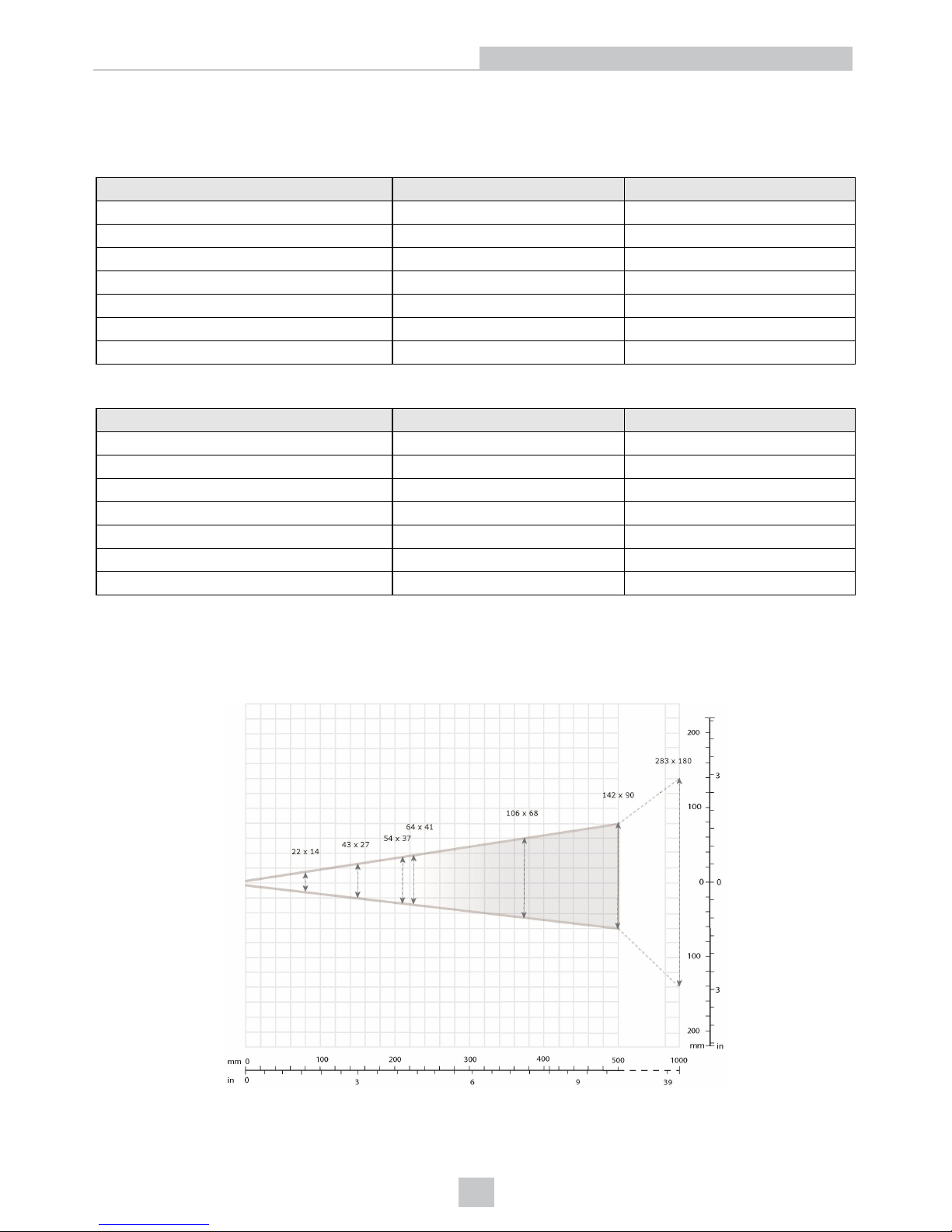
The following maps show the FoV of the DataMan 150/260 and DataMan 152/262 readers with a 16 mm lens. The
horizontal and vertical field of view is shown for working distances of 80 mm, 150 mm, 225 mm, 375 mm, 500 mm and
1000 mm.
DM150 or DM260 + 16 mm Lens
64
Optics and Lighting
Page 65
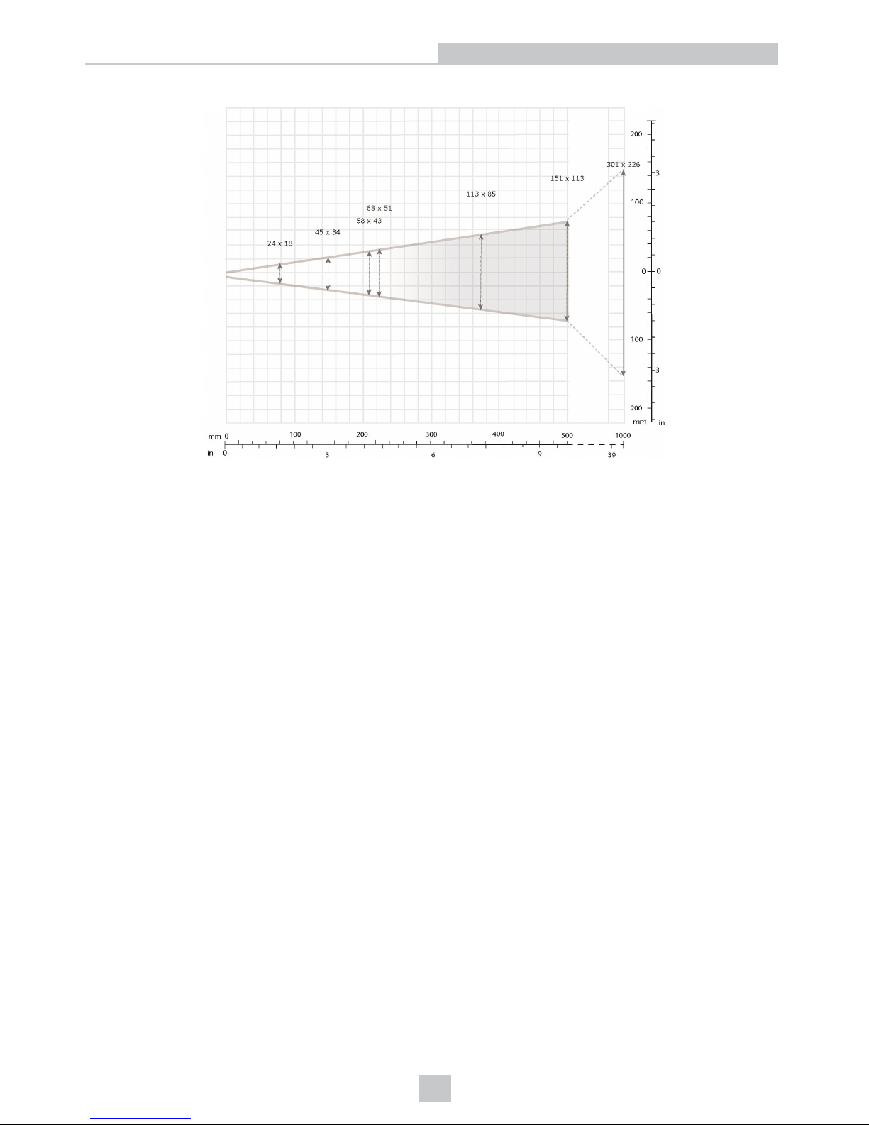
DM152 or DM262 + 16 mm Lens
65
Optics and Lighting
Page 66
DataMan 300 and 360 Series Readers Reading Distances and
Field of View
The DataMan 300 and 360 series readers: DataMan 300/360, DataMan 302/362, and DataMan 303/363 have different
fields of view because of the different regions of the sensor used by each reader.
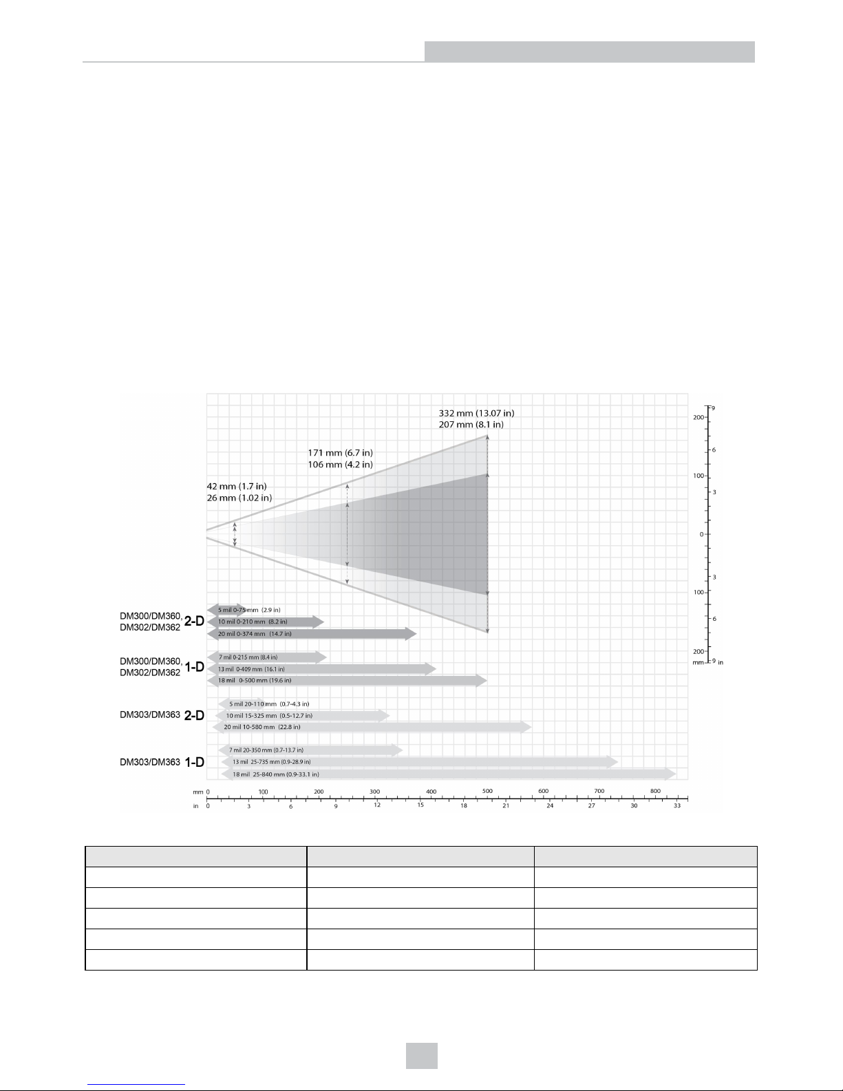
Scan Map for DataMan 300 and 360 Series Readers Using a 10.3 mm Lens
The map below shows the field of view of the DataMan 300/360, DataMan 302/362 and DataMan 303/363 readers with a
10.3 mm lens (with or without a liquid lens).
The FoV values are shown as follows:
l outer: DM302/362, DM303/363
l inner: DM300/360
The reading distances for the DM300/360 and DM302/362 readers are the same. The DM303/363 features a higher
resolution and more pixels in about the same sensor size.
The following table shows the Field of View widths in mm at various distances.
Distances in mm DM300, DM360 DM302/303, DM362/363
50 26 42
100 46 74
150 66 106
250 106 171
500 207 332
66
Optics and Lighting
Page 67
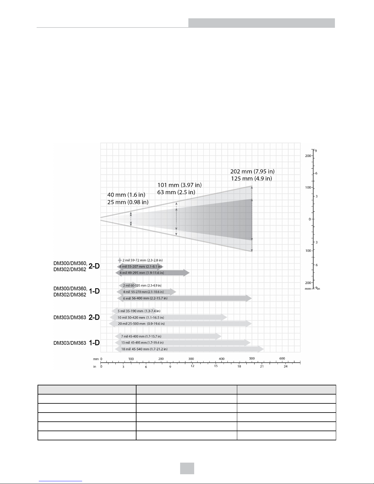
Scan Map for DataMan 300 and 360 Series Readers Using a 16 mm Lens
This map shows the field of view of the DataMan 300/360, DataMan 302/362 and DataMan 303/363 readers with a 16
mm lens.
The FoV values are shown as follows:
l outer: DM302/362, DM303/363
l inner: DM300/360
The reading distances for the DM300/360 and DM302/362 readers are the same. The DM303/363 features a higher
resolution and more pixels in about the same sensor size.
To make sure that your DM303/363 reader is able to decode at the minimum reading distances, use the reader in
combination with the extension kit or without the front cover.
The following table shows the Field of View widths in mm at various distances.
Distances in mm DM300, DM360 DM302/303, DM362/363
50 13 20
100 25 40
150 38 60
250 63 101
500 125 202
67
Optics and Lighting
Page 68
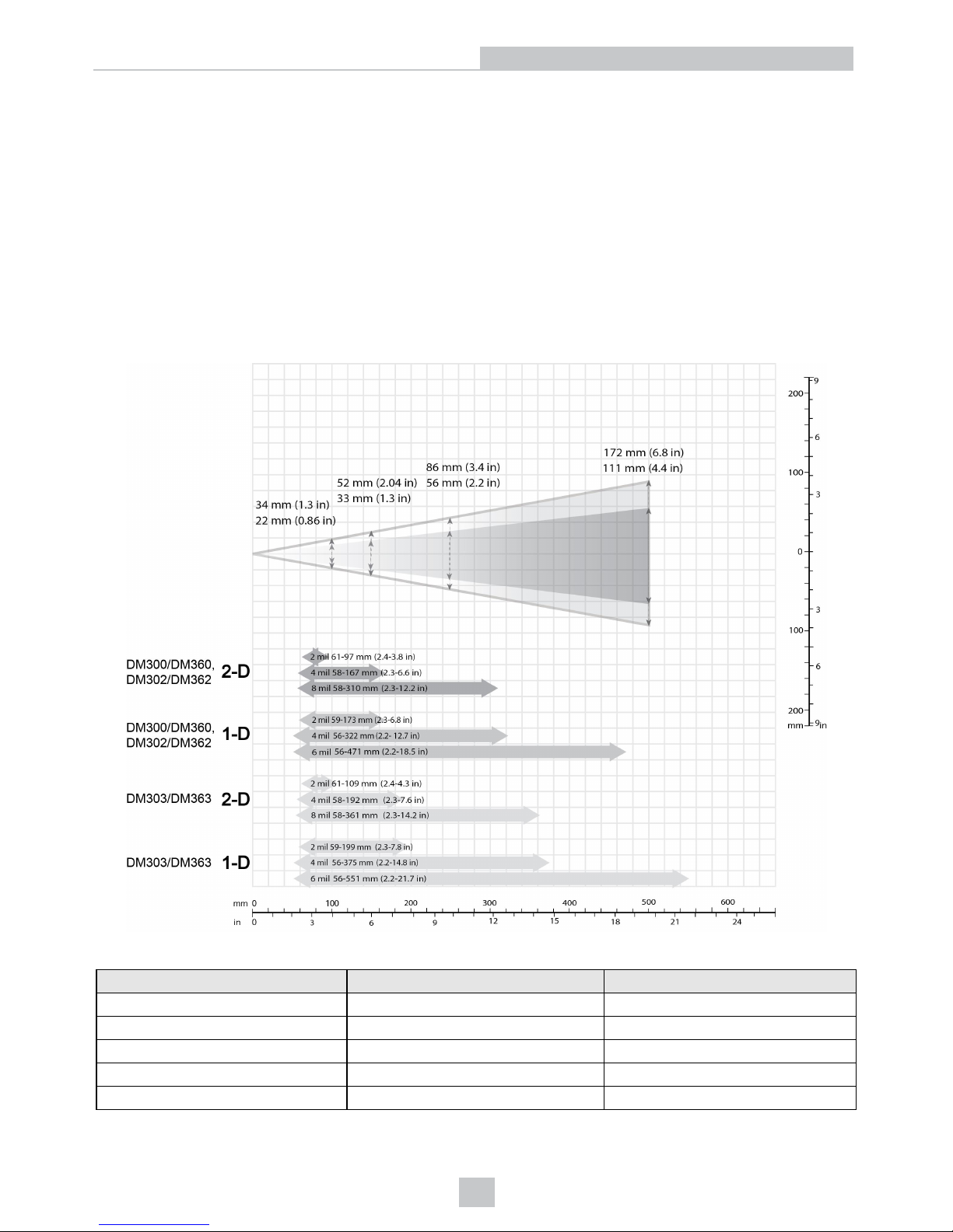
Scan Map for DataMan 300 and 360 Series Readers Using a 19 mm Lens
This map shows the field of view of the DataMan 300/360, DataMan 302/362 and DataMan 303/363 readers with a 19
mm lens (with or without a liquid lens).
The FoV values are shown as follows:
l outer: DM302/362, DM303/363
l inner: DM300/360
The reading distances for the DM300/360 and DM302/362 readers are the same. The DM303/363 features a higher
resolution and more pixels in about the same sensor size.
To make sure that your DM303/363 reader is able to decode at the minimum reading distances, use the reader in
combination with the extension kit or without the front cover.
The following table shows the Field of View widths in mm at various distances.
Distances in mm DM300, DM360 DM302/303, DM362/363
50 11 17
100 22 34
150 33 52
250 56 86
500 111 172
68
Optics and Lighting
Page 69
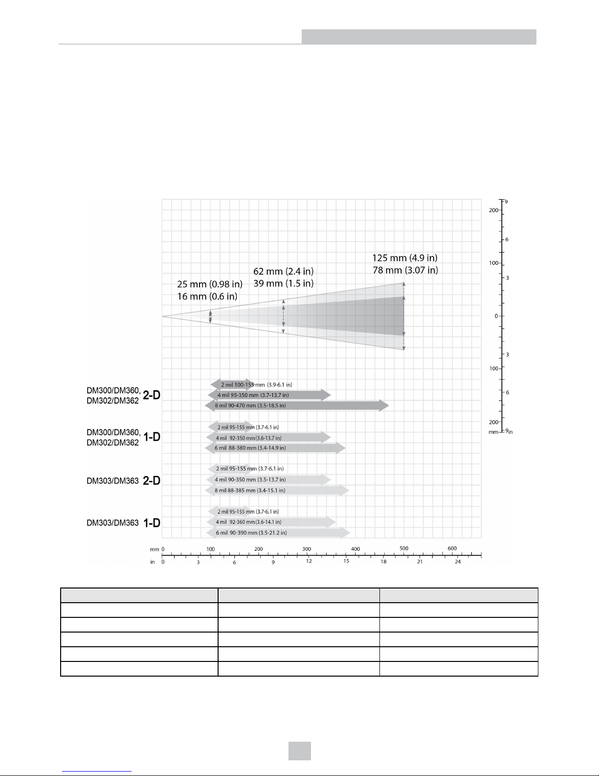
Scan Map for DataMan 300 and 360 Series Readers Using a 25 mm Lens
This map shows the field of view of the DataMan 300/360, DataMan 302/362, and DataMan 303/363 readers with a 25
mm lens.
The FoV values are shown as follows:
l outer: DM302/362, DM303/363
l inner: DM300/360
The reading distances for the DM300/360 and DM302/362 readers are the same. The DM303/363 features a higher
resolution and more pixels in about the same sensor size.
The following table shows the Field of View widths in mm at various distances.
Distances in mm DM300, DM360 DM302/303, DM362/363
50 8 12
100 16 25
150 23 37
250 39 62
500 78 125
69
Optics and Lighting
Page 70
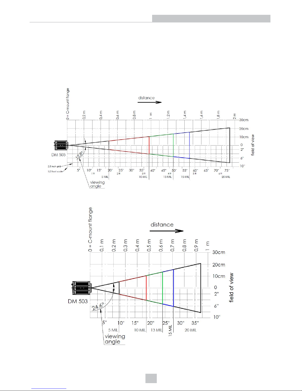
DataMan 503 Readers Reading Distance and Field of View
The following scan maps show the reading distance and field of view charts for the various lenses that can be used with
the DataMan 503 reader.
Scan Map for DataMan 503 Series Readers Using a 16 mm Lens Module
The following map shows the reading distance and field of view charts for the DataMan 503 reader with a 16 mm lens for
1-D codes. The minimum 1-D resolution is at 1.2 pixels per module.
The following map shows the reading distance and field of view charts for the DataMan 503 reader with a 16 mm lens for
2-D codes. The minimum 2-D resolution is at 2.5 pixels per module.
70
Optics and Lighting
Page 71
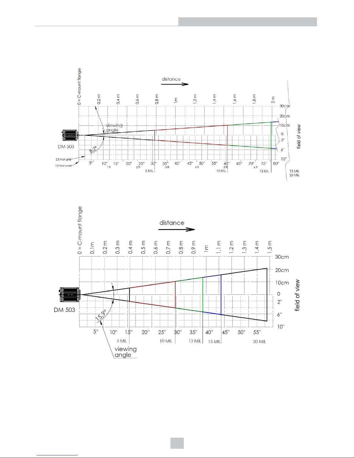
Scan Map for DataMan 503 Series Readers Using a 25 mm Lens Module
The following map shows the reading distance and field of view charts for the DataMan 503 reader with a 25 mm lens for
1-D codes. The minimum 1-D resolution is at 1.2 pixels per module.
The following map shows the reading distance and field of view charts for the DataMan 503 reader with a 25 mm lens for
2-D codes. The minimum 2-D resolution is at 2.5 pixels per module.
Scan Map for DataMan 503 Series Readers Using a 35 mm Lens Module
The following map shows the reading distance and field of view charts for the DataMan 503 reader with a 35 mm lens for
1-D codes. The minimum 1-D resolution is at 1.2 pixels per module.
71
Optics and Lighting
Page 72
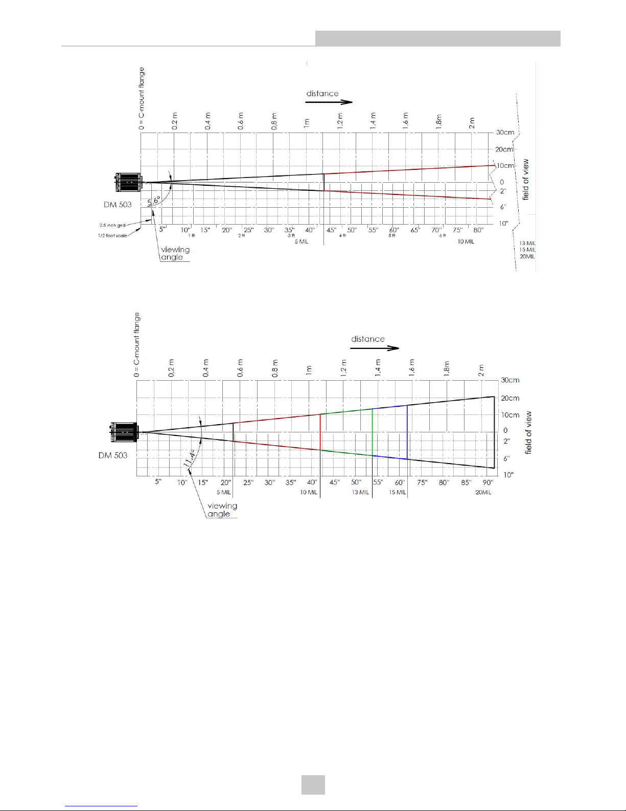
The following map shows the reading distance and field of view charts for the DataMan 503 reader with a 35 mm lens for
2-D codes. The minimum 2-D resolution is at 2.5 pixels per module.
CS-Mount Lens Characteristics
This section provides information on using CS-mount lenses.
DataMan 503 CS-Mount Lens Characteristics
CS-mount lenses must meet the following requirements to be used with DataMan 503:
l No aspect of the lens may protrude past the end of the lens threads.
l The threads must be no more than 4 mm deep.
l The maximum size lens barrel that fits within the CS-mount lens cover is 30 mm long (measured from lens mount
base) and 28 mm in diameter. You can remove the lens (and front) covers from DataMan to fit a larger lens, but
the reader will not maintain its IP rating.
72
Optics and Lighting
Page 73

Internal Lighting
This section describes the working mechanism of the built-in lighting of DataMan 50, 60, 70, 150, 260, 503 and DataMan
300 and 360 series readers.
DataMan 50 and 60 Internal Lighting
All DataMan 50 and 60 readers include built-in (internal) lighting. During operation, the DataMan 50 and 60
automatically regulate image exposure time and imager gain to produce usable image quality at the highest possible
frame rate.
As the working distance between the reader and code increases, additional light intensity or longer exposure times are
required to maintain the same image quality. When the maximum illumination intensity is reached, the frame rate may be
reduced to permit a longer exposure time.
DataMan 70, 150 and 260 Internal Lighting
All DataMan 70, 150 and 260 readers include built-in (internal) lighting. During operation, the DataMan 70, 150 and 260
automatically regulate image exposure time and imager gain to produce usable image quality at the highest possible
frame rate.
As the working distance between the reader and code increases, additional light intensity or longer exposure times are
required to maintain the same image quality. When the maximum illumination intensity is reached, the frame rate may be
reduced to permit a longer exposure time.
DataMan 300 and 360 Series Readers Internal Lighting
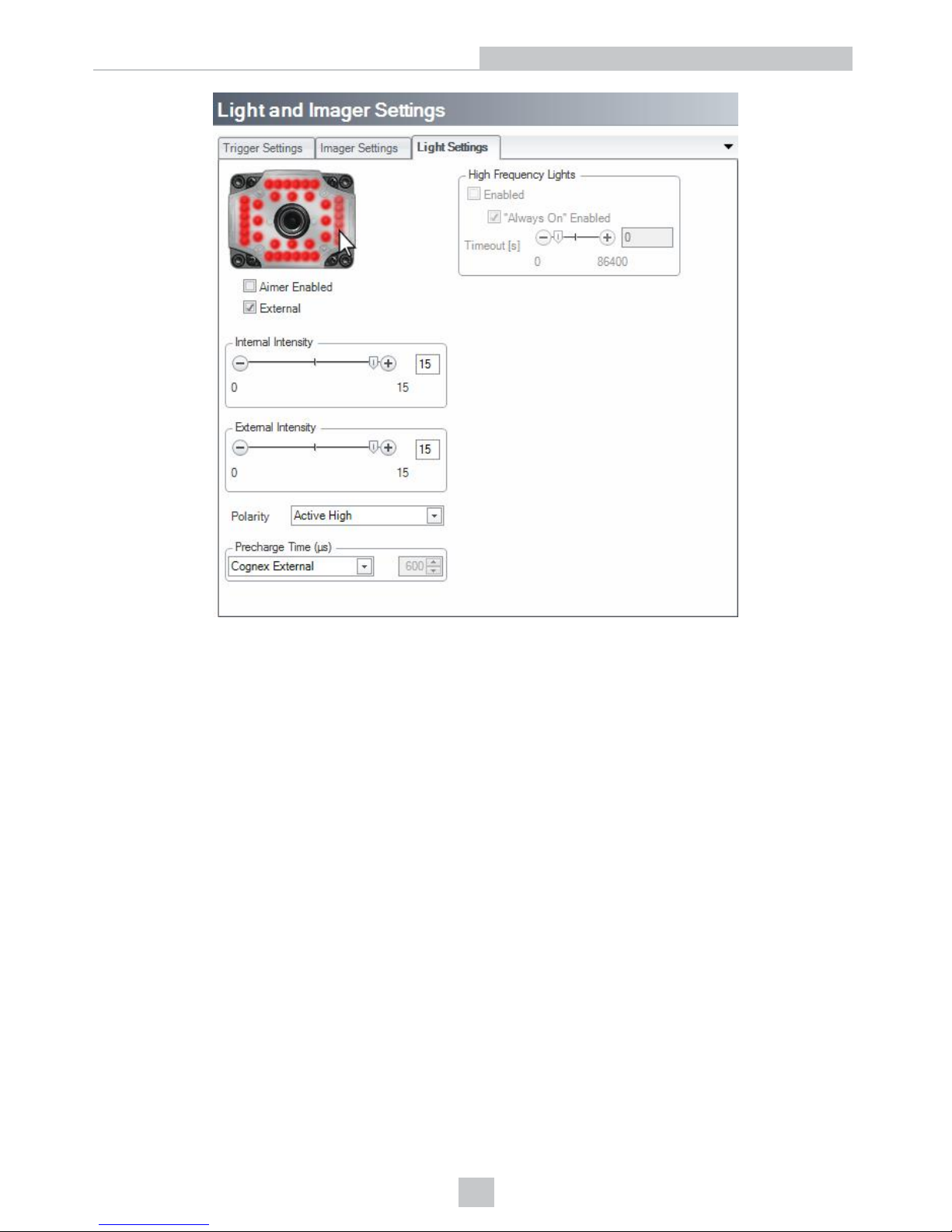
The internal illumination module offers two rings of LEDs with four quadrants each. Each quadrant is controllable
individually, that is, ON/OFF and intensity.
You can turn the quadrants ON or OFF by clicking on the dots (representing the LEDs) on the front image of the DataMan
300 or 360 in the DataMan Setup Tool’s Light and Imager Settings pane. The quadrants that are ON are displayed in
red, as shown in the example below.
73
Optics and Lighting
Page 74
74
Optics and Lighting
Page 75
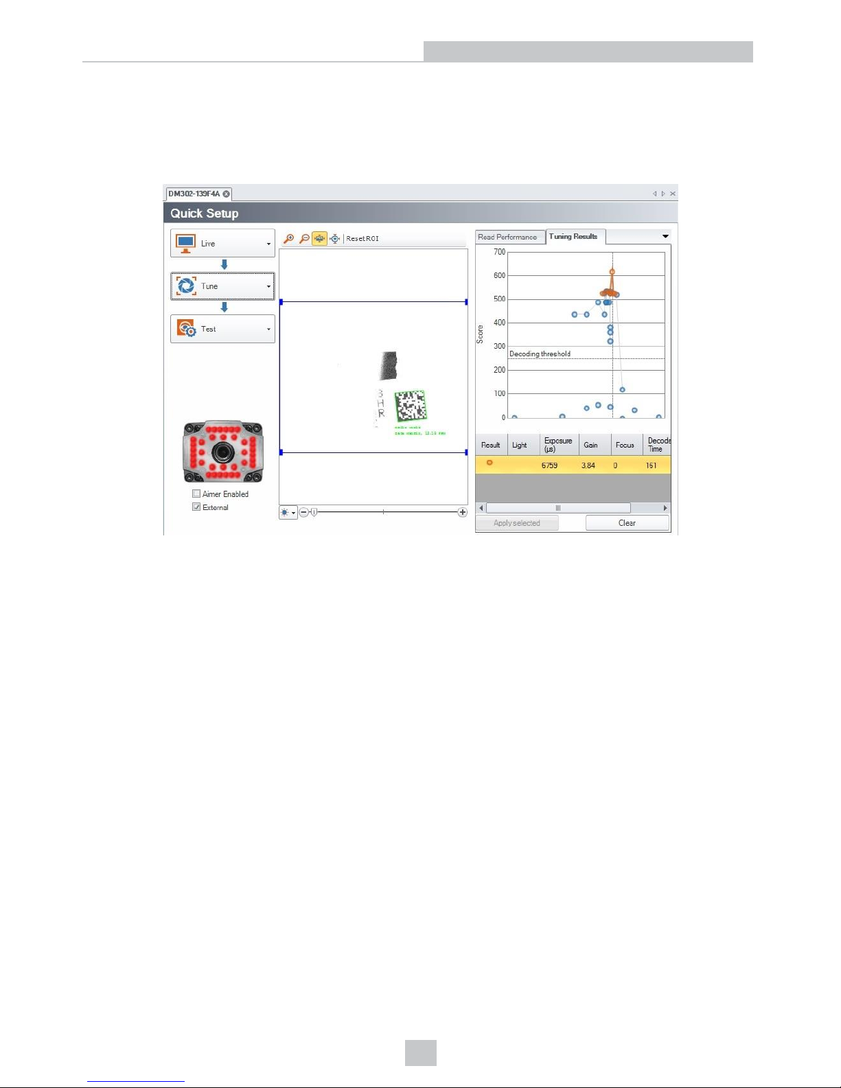
Tuning
By tuning, your DataMan 300 or DataMan 360 series reader automatically selects the best settings for the given reading
situation, based on parameters of illumination, camera and decoder properties, and focal distance. Use this feature to
create an optimum setting to read your DataMatrix codes. In the following example, the best situation is when all
quadrants are turned on.
75
Optics and Lighting
Page 76
External Lighting
This section details the external lighting options for DataMan 50, 60, 503 and DataMan 300 and 360 series readers.
DataMan 50 and 60 External Lighting
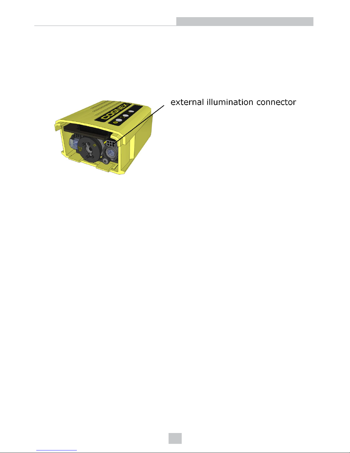
The DataMan 50 and 60 readers have a dedicated output for external light control. In addition, the DataMan 60 has an
external illumination connector on the front side of the reader.
You can control the intensity output of the external illumination connector if the external illumination you use supports
this control. Go to the Light Settings tab of the DataMan Setup Tool’s Light and Imager Settings pane, check the
External checkbox and change the intensity according to your needs.
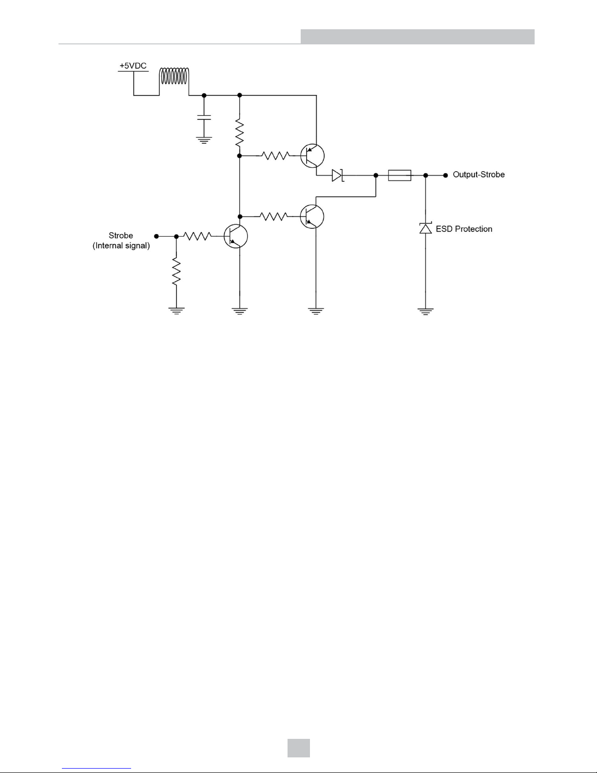
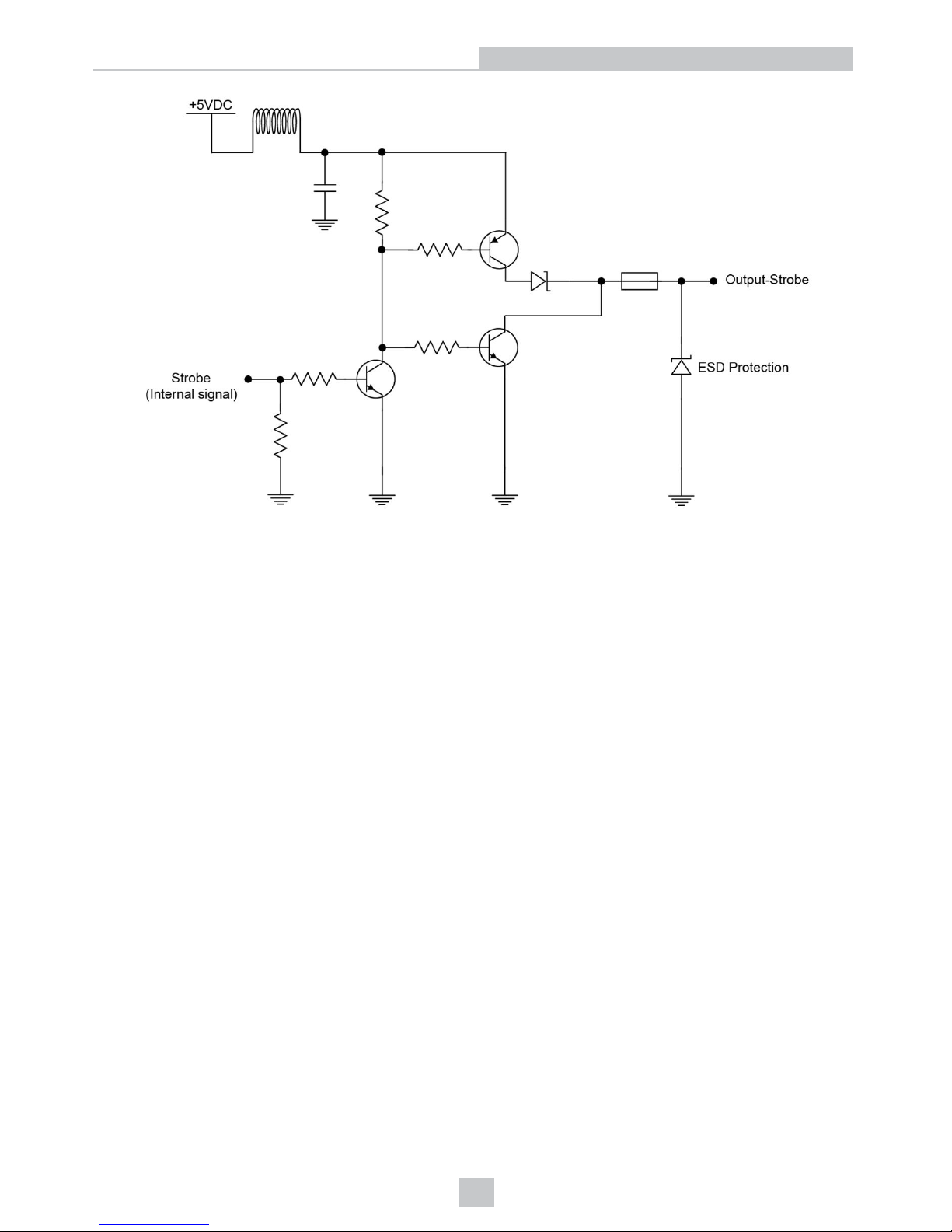
DataMan 50 and 60 Illumination Strobe Output
The strobe output is provided by a diode that is added to the push-pull circuit, with series to the pull-up transistor. This
diode blocks the higher voltage when the output is pulled up when used as open-collector type driving, but enables the
driving of high level in TTL mode.
TTL output type characteristics
High level 4.0-5.0V
Low level 0-0.4V
Output current 25 mA
Short-circuit current 125 mA
Short-circuit proection multifuse – 50mA
Open-collector output type characteristics
Output voltage range 0-26V
Low level 0-0.4V
Output current 25 mA max
Short-circuit current 125 mA
Short-circuit protection multifuse – 50 mA
The following figure shows the wiring diagram of the illumination strobe output.
76
Optics and Lighting
Page 77
77
Optics and Lighting
Page 78
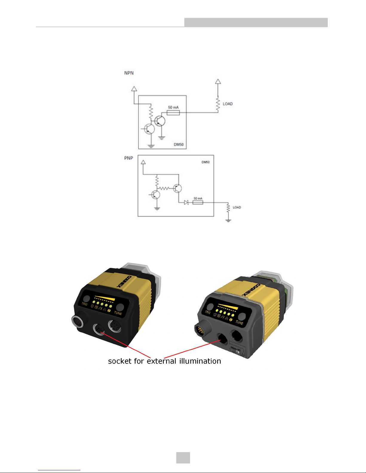
DataMan 50 and 60 External Load Strobe Output
The following image shows the external load strobe output for the DataMan 50. The DataMan 60 has the same
characteristics.
DataMan 300 and 360 Series Readers External Lighting
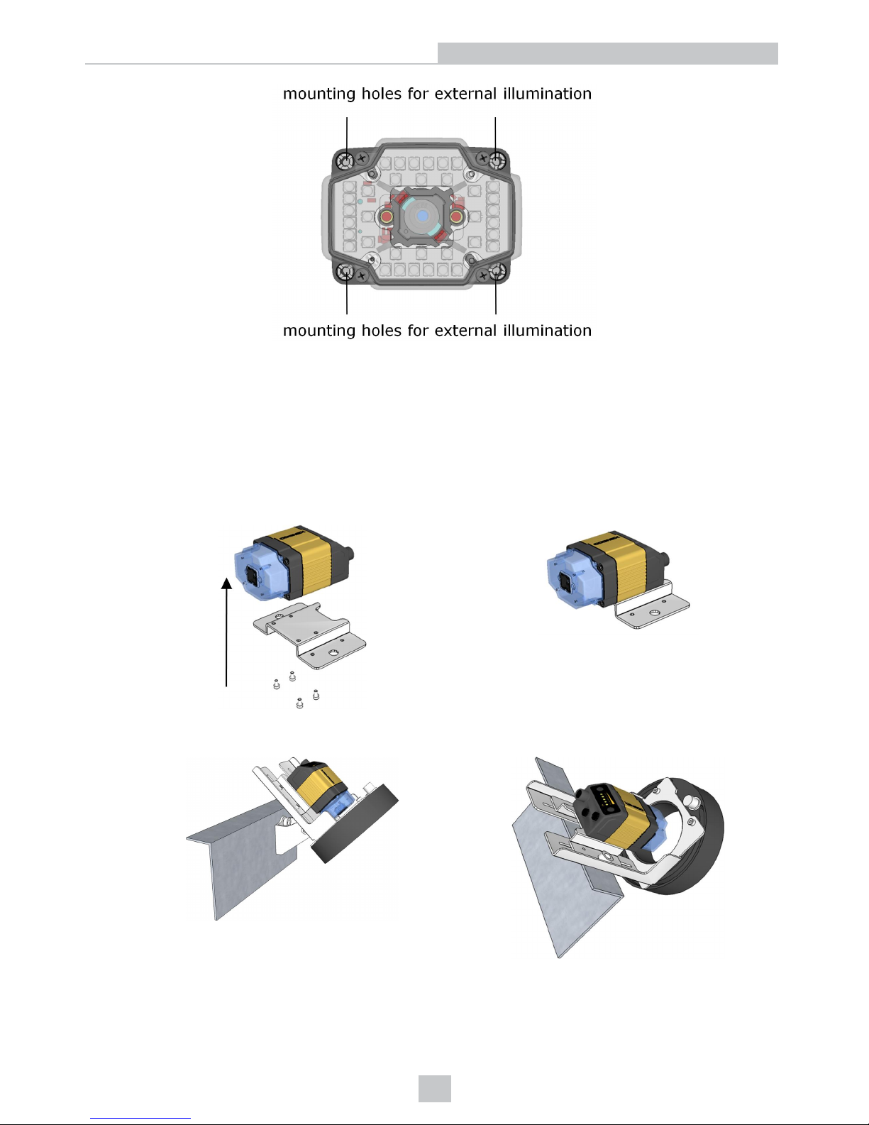
On the back of the reader, there is a socket dedicated to external light control.
There are four mounting holes on the front of the reader to mount external illumination.
78
Optics and Lighting
Page 79
You can control the intensity output of the external illumination connector if the external illumination you use supports
this control. Go to the Light Settings tab of the DataMan Setup Tool’s Light and Imager Settings pane, check the
External checkbox and change the intensity according to your needs.
External Light Mounting Brackets
You can mount your reader using external light mounting brackets. The brackets are intended to mount any of the
different lights to the reader. They can also be used to mount the reader (with lights attached) to your machine. Pivot
mounting, as illustrated, is optional. Perform the following steps:
1. Mount your reader on the camera plate and attach the screws.
2. Mount your reader with the camera plate attached to any of the external light bracket adapters.
Choose one of the following light options:
79
Optics and Lighting
Page 80
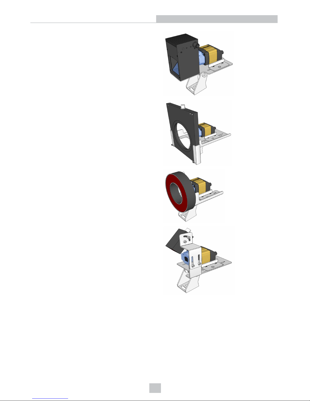
l Using coaxial (DOAL) light
l Using dark field light
l Using ring light
l Using spot light
DataMan 50, 60, 300 and 360 External Lighting Duration
In all cases, as soon as the trigger is detected, external illumination is turned on. There is a 600 µSec pre-charge time
before exposure starts; the lighting is on during this period. In the DataMan Setup Tool’s Light and Imager Settings pane,
you can select Automatic Exposure (autoregulation) or Manual Exposure (non-autoregulation) according to your needs.
If you use a DataMan 302 reader with full Field of View (FoV), consider the following:
80
Optics and Lighting
Page 81

l In non-autoregulation cases, exposure occurs for an amount of time you specify. You can configure this time in
the DataMan Setup Tool’s Light and Imager Settings pane. When exposure ends, illumination is turned off.
Altogether, the exposure duration equals the exposure time you set and the 600 µSec pre-charge time.
l If autoregulation is enabled, the duration can vary depending on the maximum allowed exposure value
configured and the computed exposure time (which will be different for each acquisition). To calculate a ”worst
case” duration, set a maximum exposure value, and the longest the lights will be on is
600 uSec precharge time + max exposure time
Exposure occurs for the amount of time determined by autoregulation. When exposure ends, illumination is turned off. If
you use a reduced FoV for a DataMan 50, 60, 300 or 360 reader, the image transfer time will scale proportionally to the
FoV/Sensor size.
DataMan 503 External Lighting Duration
In all cases, as soon as the trigger is detected, external illumination is turned on. There is a user adjustable µSec precharge time before exposure starts; the lighting is on during this period. In the DataMan Setup Tool’s Light and Imager
Settings pane, you can select Automatic Exposure (autoregulation) or Manual Exposure (non-autoregulation) according
to your needs.
l In non-autoregulation cases, exposure occurs for an amount of time you specify. You can configure this time in
the DataMan Setup Tool’s Light and Imager Settings pane. When exposure ends, illumination is turned off.
Altogether, the exposure duration equals the exposure time you set, the adjusteble µSec pre-charge time, plus a
maximum 17,15 ms image transfer time.
l If autoregulation is enabled, the duration can vary depending on the maximum allowed exposure value
configured and the computed exposure time (which will be different for each acquisition). To calculate a ”worst
case” duration, set a maximum exposure value, and the longest the lights will be on is
Max. allowed precharge time + max exposure time
Exposure occurs for the amount of time determined by autoregulation. When exposure ends, illumination is turned off.
81
Optics and Lighting
Page 82

Operations Guide
This section contains information about configuring and using your DataMan reader.
Trigger Modes
The fixed-mount DataMan readers provide the following trigger modes:
Self-Trigger
DataMan fixed mount readers support self-triggered operation. In self-trigger mode, the reader automatically detects and
decodes codes in its field of view. The high-speed image acquisition and processing capabilities of the DataMan allow it
to detect and decode codes.
Self-trigger mode has the following characteristics:
l Ease of setup. No external trigger is required.
l Flexible timing. Parts can arrive at irregular intervals.
l Maximum throughput.
Manual
Manual triggering starts acquiring and attempting to decode images when you send an external trigger. The reader
continues to acquire and attempt to decode images until you stop the external triggering. 2-D DPM codes are
automatically learned.
Manual trigger mode is typically used during debugging or system design.
Burst
Burst triggering acquires a pre-defined number of images when an external trigger is signaled, then attempts to decode
the acquired images. You can control the interval between the acquired images. The number of images acquired per
burst depends on the size of the region of interest that you specify.
Continuous
Continuous triggering begins acquiring images based on a single external trigger and continues to acquire and decode
images at a user-specified interval until a symbol is found, or until multiple images containing as many codes as
specified in multicode mode are located. The external trigger can be configured as a latch (acquisition continues while
the line is held high) or acquisition can be started on the first pulse, stopped on the second pulse. If you scan items on a
conveyor, make sure that each item reaches trigger OFF before the next item generates trigger ON.
Single
Single triggering acquires a single image and attempts to decode any symbol it contains, or more than one symbol in
cases where multicode is enabled. The reader relies on an external trigger source.
Presentation
Presentation triggering repeatedly scans for a symbol and decodes it whenever one is detected. The reader relies on an
internal timing mechanism to acquire images.
82
Operations Guide
Page 83
Presentation mode is similar to manual trigger mode, without using the trigger as a signal to start acquisition.
Package Detection Support
You can connect your package detection sensor to one of the digital inputs of your DataMan reader. When the reader
receives a signal that a package is detected, images that the reader collected are not discarded at the end of the trigger.
This way you can make sure that there was a package there, only the code was not readable. Looking at the No Read
images will help you find out why there was no decode results.
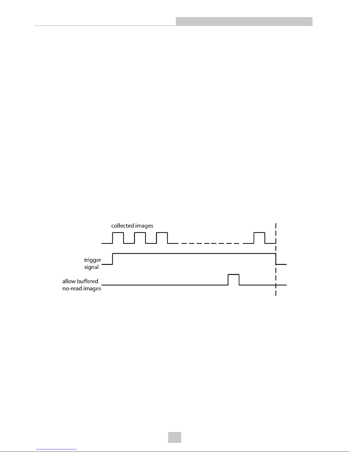
Package detection is only supported with Continuous trigger mode. Continuous (external) trigger mode means that the
trigger stops if the event generating the trigger stopped, or if there is a good read. Until the trigger stops, the reader
collects images. These are No Read images (otherwise the trigger would stop).
You can use this feature in a stand-alone configuration, or in a master/slave configuration. In the latter case, connect the
sensor to the Master device. The Master will initiate a request to save images and collect the images from the slaves.
To make sure that the No Read images are collected, perform the following:
1. Connect your package detection device to one of the Inputs of your reader.
2. On the Inputs tab of the DataMan Setup Tool’s System Settings pane, check Allow Buffered No-Read Images
on the input you connected your reader to.
3. On the Image Buffering tab of the DataMan Setup Tool's Buffering and Transfer pane, change What Results to
Buffer to All, or No Read.
l In the case of All, good reads are also saved together with No Reads.
l In the case of No Read, the image is buffered if the reader fails to read.
The following diagram shows the working mechanism:
The signal from the sensor tells the reader not to discard the collected images at the end of the trigger event.
Test Mode
Test mode lets you configure and test a reader that is connected to a production line without needing to slow down or
stop your line. To enter Test mode,
l Press the button (to which you previously assigned this function) on the device for 3 seconds
l Send a DataMan Control Command (DMCC)
l Click the Test Mode button in the DataMan Setup Tool
While in test mode, the reader, by default, ignores all external trigger sources and disables all input and output lines.
Test mode provides two ways for you to test your reader configuration:
83
Operations Guide
Page 84

l Check Automatic Triggering, and the reader will simulate external triggers at the interval that you specify. This
allows you to examine the result of each trigger and images with the configuration used in production but at a
slower rate. Because inputs and outputs are disabled, the reader will not interfere with the normal operation of
your line.
l If you click Accept Trigger Batch, the reader will accept and process a limited number of external triggers (you
can specify the number) at production speed. You can then examine these results and corresponding images to
verify how the reader is processing triggers in production.
If need, you can enable both inputs and outputs during test mode, but you may encounter I/O process latencies.
Code Training
You can train the DataMan fixed mount readers for single or multiple codes. Training can improve performance, since
the reader does not have to determine code parameters as it reads the codes.
Code training is only supported for the following trigger modes:
l Burst
l Continuous
l Self (internal trigger)
l Single (external trigger)
You can train codes in the following ways:
l With an image showing the code or codes to train present in the DataMan Setup Tool's Image Toolview, click the
Train Code button on the Quick Setup pane.
l Use the TRIGButton tab in the System Settings pane to configure the button to train codes, then present the
codes to the reader and press and hold the button for 3 seconds.
l Use the Inputs tab in the System Settings pane to configure a discrete input to perform code training.
Automatic Code Training for DPM Symbols
Manual and Presentation modes automatically train 2-D symbols. This improves robustness on DPM symbologies when
reading consecutive parts of the same type. Sequential dissimilar parts will still decode.
Image Buffering and Image Recording
You can configure the DataMan fixed-mount readers to store selected images in the memory of the reader.
You can select the following options on which images to store:
l No images.
l No-read images. (Images where the reader was triggered but either no code was present or the code could not
be decoded.)
l Images where a code was successfully decoded.
l All images.
If you select all images or no-read images, you can specify a sampling rate to control the number of images that are
buffered.
84
Operations Guide
Page 85
Retrieving Buffered Images
You can use the DataMan Setup Tool to view and download images from your DataMan device, or you can configure the
DataMan reader to automatically transfer the buffered images to an FTP server that you specify.
For more information, see the DataMan Setup Tool Quick Reference Guide.
DataMan Master/Slave Configuration
Overview
If you have multiple DataMan fixed mount readers connected to the same network, you can configure multiple readers to
use group triggering. Readers configured to use group triggering all acquire an image simultaneously, and then
combine their individual read results to form a composite result.
There are two important aspects to group triggering:
l Readers configured for group triggering consolidate reader results from among all readers in the group and
transmit them from the master reader only. This simplifies the task of collecting and processing read results from
multiple readers.
l Readers configured for group triggering can be triggered simultaneously based on a single input trigger signal
received by the master reader.
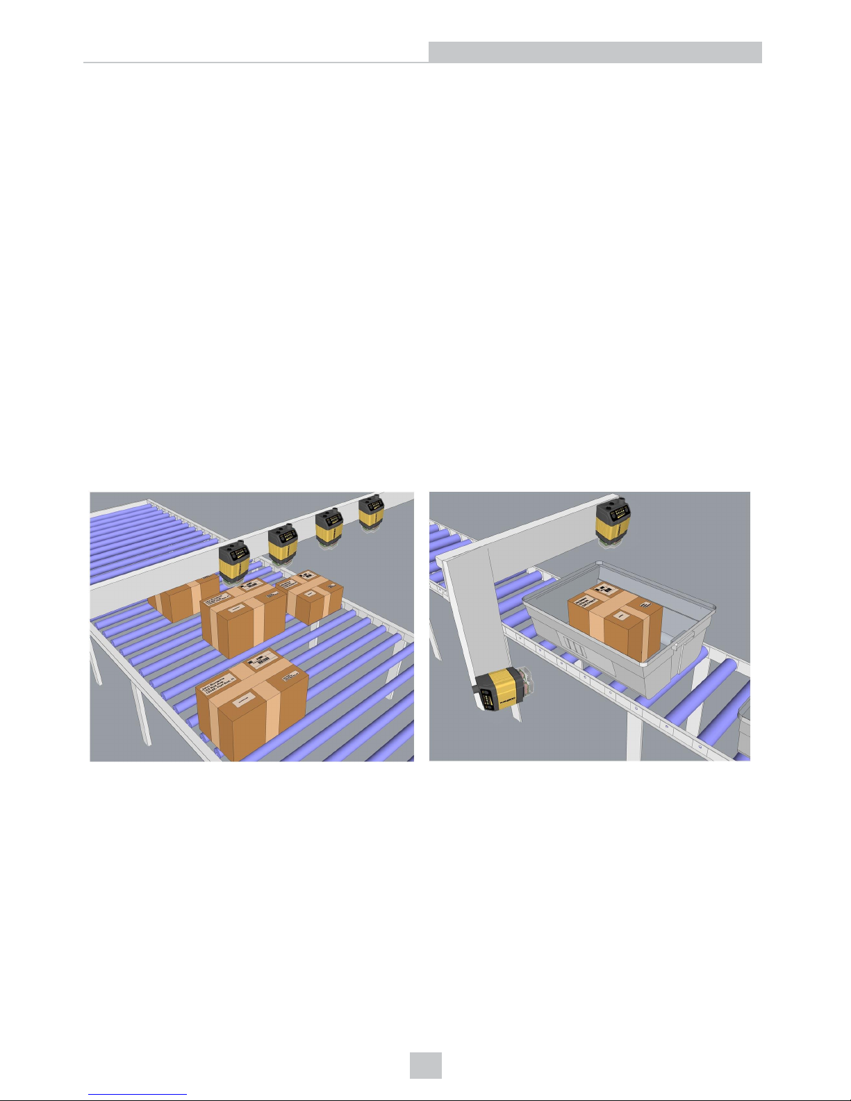
Master/Slave configurations are typically used to expand the field of view for broad conveyor applications and to read
codes from multiple surfaces of packages or objects:
Master
Within a group, one reader is defined as the master. When the master reader is triggered (regardless of what type of
trigger it uses), all the readers in the group are also triggered. For self-trigger mode, you must designate the master
reader explicitly. For externally triggered modes (single, burst, and continuous), whichever reader receives the trigger is
designated the master for that acquisition. (In most cases, only a single reader in the group will be connected to the
external trigger.)
To account for network latency, you specify a trigger delay for the master reader in the group. When the master is
triggered, it immediately sends triggers to the other group members, but delays its own acquisition for the specified
delay, allowing the trigger signal to reach the other readers. You can also configure a separate trigger timeout, which will
85
Operations Guide
Page 86
cause the master reader to wait for a specified period of time for slave readers to send data before collecting the results
and transmitting them.
After a read attempt, only the master reader transmits a result. It combines all of the available results from the other
readers in the group in the same way that multicode results are combined.
Slaves
In many applications, the master/slave configuration is set to trigger the slave readers whenever the master reader is
triggered. If the slave readers are configured for Self triggering, then they will also trigger whenever they detect a code. In
this case, the master reader will generate and transmit a read result whenever any reader detects a code. This result
aggregation greatly simplifies multiple reader operation.
Data Formatting
When the reader is triggered, the result string will be formatted as you specified, before it is transmitted to the master
reader for aggregation. Note, however, that you have to check Standard Formatting Enabled for the master and supply
the formatting tokens you want to use for the slaves. Any data formatting that you specify for the master reader will be
applied to the formatted result strings produced by the slave readers. The data formatting pane includes a token that
allows you to insert the name of the reader generating the result string; you can use this to identify which reader
produced which result.
Limitations
l No image buffering and recording is supported for any reader that is part of a group.
l Presentation mode triggering is not supported.
l Master-Slave triggering only works correctly if Master and Slave use specific, allowed combinations of trigger
modes. They are the following:
l Self/Self
l Single/Burst, Single/Single, Burst/Burst, Burst/Single
l Manual/Continuous, Manual/Manual, Continuous/Continuous, Continuous/Manual
Synchronized Acquisition
Synchronized Acquisition is only available for the DataMan 503. In Single, Burst, Continuous, and Self trigger modes, it
is possible to synchronize image acquisition on multiple devices using the synchronization interface.
Synchronization allows using one shared strobe illumination to expose all sensors simultaneously. You can synchronize
multiple readers, with optionally triggering them in a defined sequence to avoid that opposing readers blind each other.
Note: This and other imager settings will not get synchronized by this mechanism - for example, you must configure
exposure and gain on each reader individually.
This feature only synchronizes the actual image acquisition, triggering happens through the existing master-slave
mechanism.
Enable Synchronized Exposure on the DataMan Setup Tool’s Master/Slave pane. Set the Acquisition Delay (μs)
(relative to the received signal through the synchronization interface) on each reader individually to optionally define an
exposure sequence in case the illumination of some readers might affect other readers.
You must also set which two readers on the ends of the synchronization interface bus are bus terminators by checking
the End of Sync Cable checkbox for the currently connected devices at the end of a sync cable.
86
Operations Guide
Page 87
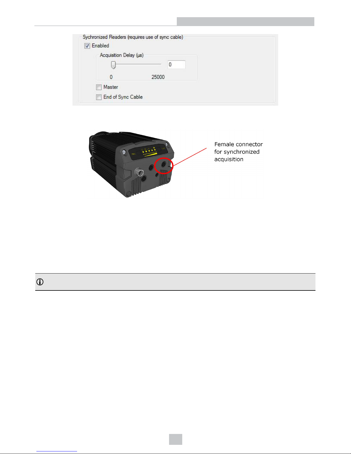
Connecting DataMan 503 Devices Through the Synchronized Acquisition Cable
Plug the synchronized acquisition cable into the dedicated connector on the DataMan 503.
If you are connecting more than two DataMan 503 devices, you need a Y connector with female ends to be able to use
the synchronized acquisition cables.
Synchronized Acquisition based on Precision Time Protocol (PTP)
Synchronized acquisition based on PTP is only available for DataMan 36x readers. In Single, Burst, Continuous, and
Self trigger modes, it is possible to synchronize image acquisition on multiple devices using the synchronization
interface.
Synchronization allows using one shared strobe illumination to expose all sensors simultaneously. You can synchronize
up to 16 readers, with optionally triggering them in a defined sequence to avoid that opposing readers blind each other.
Note: This and other imager settings will not get synchronized by this mechanism - for example, you must configure
exposure and gain on each reader individually.
This feature only synchronizes the actual image acquisition, triggering happens through the existing master-slave
mechanism.
Enable PTP on the DataMan Setup Tool’s Master/Slave pane under Synchronized Readers (IE1588). Set Slave Only
accordingly on each reader individually to define Master/Slave reader relations.
87
Operations Guide
Page 88

Using C/CS-Mount Lenses
Aperture Setting
Because of the extreme sensitivity of the DataMan image sensor, for most applications, a small aperture (F8 or less)
provides sufficient light for full-rate image processing while also maximizing depth of field.
Selecting Optimum Focus
You can enter live video, but for best focus optimization, place the reader in automatic trigger mode and adjust the focus
until the peak read rate is obtained.
Optimizing Performance
Read Interval and Timeout Configuration
Careful configuration of the read interval (Self and Continuous triggering) or timeout value (Burst mode) can improve
read rates and throughput.
l If your application uses clearly printed symbols, you can improve performance by reducing the interval or timeout
value. This is because DataMan acquires images at such a high rate that a shorter timeout or interval allows the
reader multiple chances to decode the symbol.
l If your application experiences poorly printed or degraded symbols, increasing the interval or timeout value can
improve performance by allowing the DataMan to spend more time decoding difficult images.
In all cases, make sure that you specify an interval that allows the reader to capture at least one image of the symbol.
Optimizing Burst Trigger Parameters
Since a Burst trigger is ideal for moving applications, it is necessary to determine the correct burst size and interval in
order to capture the desired length of the part as it moves under the camera. Once the interval time is determined, you
can adjust the size of the burst depending on the length of the part. The variables necessary for this calculation are:
1. Line speed in mm per second
2. Code size w/quiet zone in mm
3. FOV = Field of View (x or y) in mm
You can then use the following equation to determine the interval time:
Interval Time = 1000 * ((FOV – 2(Code Size)) / Line Speed)
Once the interval time is determined, the size of the burst can be adjusted depending on the length of the code to
capture. The max object length in mm is:
Burst Size * (FOV – (2*Code Size))
The (2 * Code Size) variable allows for overlap of the frames taken. This takes into consideration the condition where the
code is slightly out of the field of view in one frame (acquisition). The (2 * Code Size) will overlap the field of view
between successive frames and allow the code to be viewed in the field of view of the next frame.
88
Operations Guide
Page 89
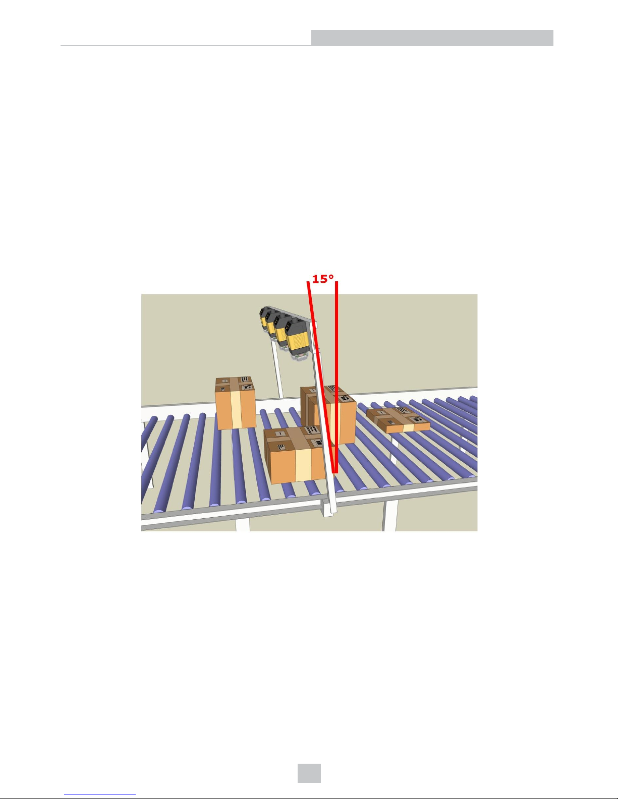
Reducing DataMan Processing Requirements
The more information that you can provide to DataMan about your application, the less work – and processing time – will
be required to decode symbols.
l Only enable the symbologies that your application uses. Disabling unused symbologies reduces processing
time.
l Train codes.
l Only enable extended mode decoding if your application requires it.
Avoiding Reflections and Glare
If the DataMan is mounted perpendicular to the surface containing the code to be read, reflections from the built-in
illumination system can cause reflections and glare that may reduce decoding performance.
You can avoid this problem by mounting the reader at a 15° angle from vertical.
89
Operations Guide
Page 90
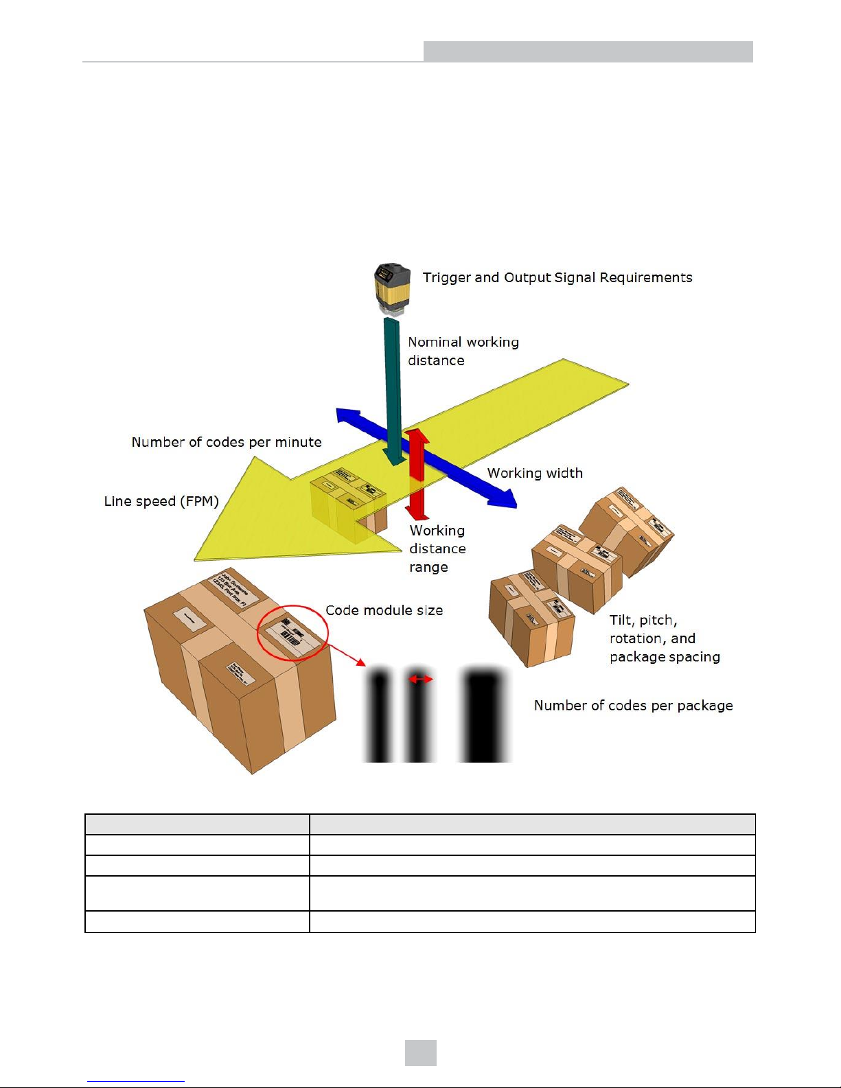
Application Guide
This section provides specific recommendations tailored to specific types of applications. Except for the sections about
Multi-Reader Configurations and Variable Size Box Conveyer, all sections apply to all the DataMan fixed-mount readers.
Understanding Your Application Envelope
A wide variety of factors affects the performance and capabilities of the DataMan in a given application. You can think of
this collection of factors as your application’s envelope:
The following table describes the different parameters that define a DataMan application envelope.
Parameter Description
Linespeed The linear speed of the part surface containing the code to decode.
Nominal working distance How far the code is from the front of the DataMan.
Working distance range The range of distances, with respect to the nominal working distance, at which
codes may be present.
Working width The width of the area in which codes may appear.
90
Application Guide
Page 91
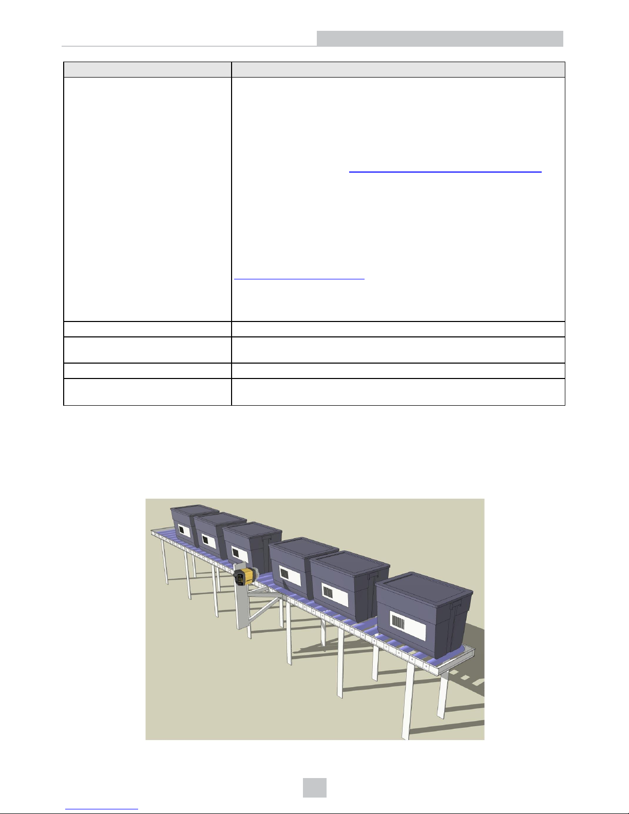
Parameter Description
Tilt, pitch, rotation, and package
spacing
The degree to which a code may be rotated, tilted, or pitched with respect to a
plane perpendicular to the DataMan optical axis.
Package spacing means a distance in time. If you use a conveyor that moves
very fast, you need more space between the boxes. If it moves very slow, you
need less space. In general, the minimum time distance between boxes must
be greater than the distance between trigger on and trigger off.
Tilt and pitch should be limited to 15-20 degrees in most cases, while rotation
may be absent or may occur up to 360 degrees (omnidirectional reading).
As described in the section Reducing DataMan Processing Requirements, the
more information that you can provide to DataMan about your application, the
less work – and processing time – will be required to decode symbols.
l Only enable the symbologies that your application uses. Disabling
unused symbologies reduces processing time.
l Train codes.
l Only enable extended mode decoding if your application requires it.
Avoiding Reflections and Glare, you should mount the reader so that the
surface containing the code to be read is not perpendicular to the reader. If
your application includes tilt or pitch, make sure that the reader is mounted so
that even at maximum tilt or pitch, the reader still is angled with respect to the
surface being read.
Code module size The size of a code element (typically the smallest bar) in Mils.
Codes per minute The maximum number codes that pass in front of the reader location per
minute.
Codes per image The number of codes visible at the same time.
Trigger and output signal requirements Whether an external trigger signal is available or a discrete output signal is
required.
The following sections describe typical application envelopes for typical DataMan code reading applications, along with
suggested configuration values.
Tote Scanning
Tote scanning applications typically involve reading a single barcode that is relatively well-fixtured.
91
Application Guide
Page 92
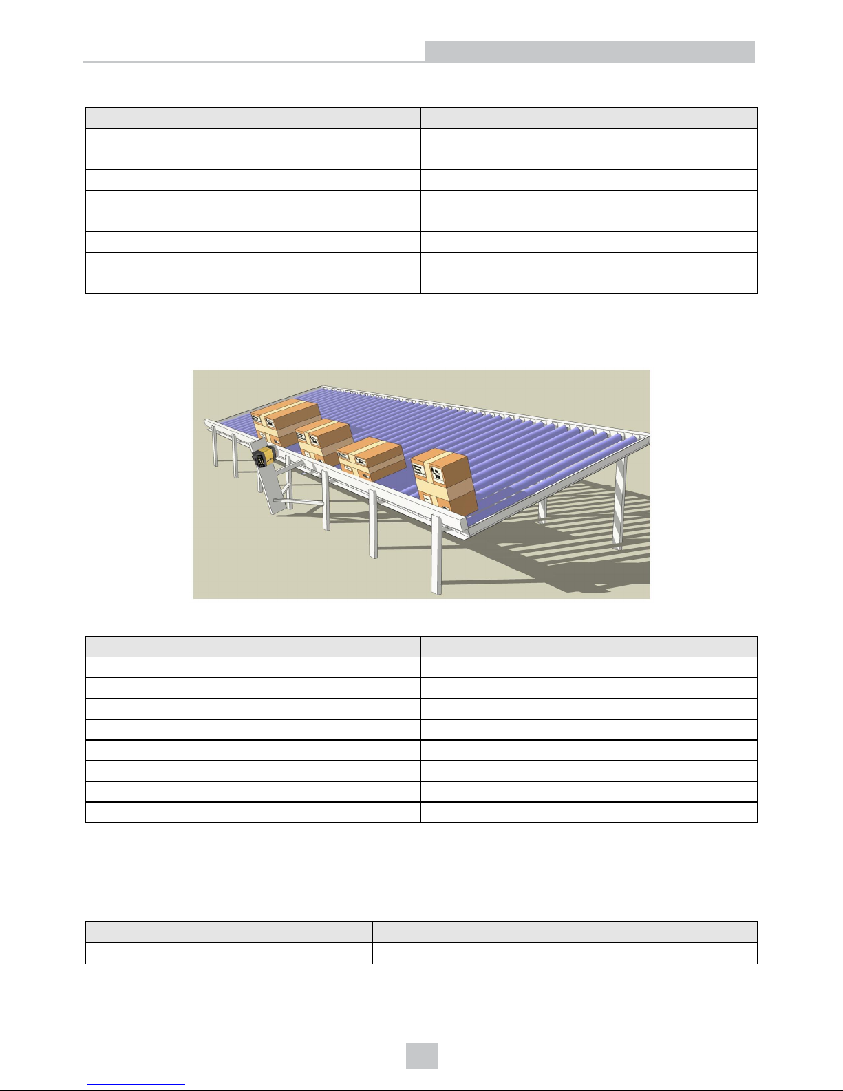
The following table lists typical values for this application:
Parameter Typical Values
Line speed 50 FPM
Nominal working distance 6-12"
Working distance range +/- 5"
Working width 6"
Tilt, pitch, and rotation +/- 2°
Code module size 20 Mil
Codes per minute 20-30
Trigger and output signals Optional
Side Scanning
Side scanning applications typically involve reading a single barcode at a consistent distance but a variable offset.
The following table lists typical values for this application:
Parameter Typical Values
Line speed 200-300 FPM
Nominal working distance 6-12"
Working distance range +/- 1"
Working width 12-24"
Tilt, pitch, and rotation +/- 2°
Code module size 20 Mil
Codes per minute 100-200
Trigger and output signals Optional
Side Scanning (Large Field)
Side scanning applications typically involve reading a single barcode at a consistent distance but a variable offset.
The following table lists typical values for this application:
Parameter Typical Values
Line speed 200-300 FPM
92
Application Guide
Page 93
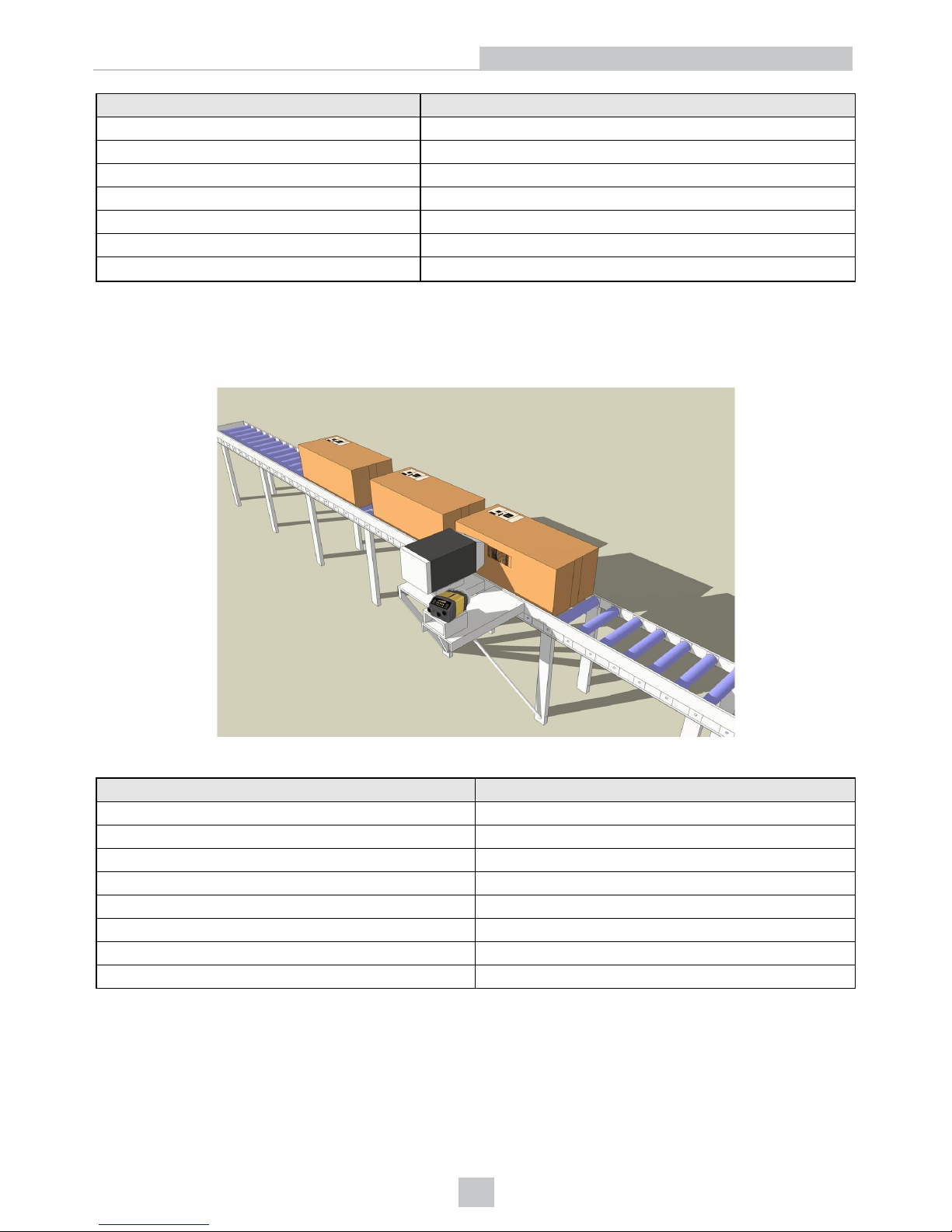
Parameter Typical Values
Nominal working distance 6-12"
Working distance range +/- 1"
Working width 12-24"
Tilt, pitch, and rotation +/- 2°
Code module size 20 Mil
Codes per minute 100-200
Trigger and output signals Optional
Print Verification (Carton Coding and Print & Apply)
This configuration reads and verifies codes from packages immediately after they are applied. The codes may be printed
directly on the object (carton coding) or on a label (print & apply).
The following table lists the typical values for this application:
Parameter Typical Values
Line speed 200-300 FPM
Nominal working distance 5-10"
Working distance range +/- 0.5"
Working width 2-4"
Tilt, pitch, and rotation +/- 2° (pitch, tilt, and rotation)
Code module size 20 Mil
Codes per minute up to 200
Trigger and output signals Likely
93
Application Guide
Page 94
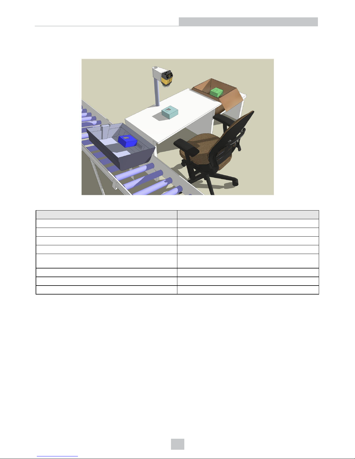
Manual Presentation Scanning
This configuration reads codes from objects presented manually.
The following table lists the typical values for this application:
Parameter Typical Values
Line speed N/A
Nominal working distance 10-20"
Working distance range +/- 10-
Working width 10-20
Tilt, pitch, and rotation
+/- 20° (pitch and tilt)
360° (rotation)
Code module size 20 Mil
Codes per minute 10-20
Trigger and output signals Possible
94
Application Guide
Page 95

Precautions
Observe these precautions when installing the Cognex product, to reduce the risk of injury or equipment damage:
l To reduce the risk of damage or malfunction due to over-voltage, line noise, electrostatic discharge (ESD), power
surges, or other irregularities in the power supply, route all cables and wires away from high-voltage power
sources.
l Changes or modifications not expressly approved by the party responsible for regulatory compliance could void
the user’s authority to operate the equipment.
l Cable shielding can be degraded or cables can be damaged or wear out more quickly if a service loop or bend
radius is tighter than 10X the cable diameter. The bend radius must begin at least six inches from the connector.
l Class A Equipment (broadcasting and communication equipment for office work): Seller and user shall be
notified that this equipment is suitable for electromagnetic equipment for office work (Class A) and can be used
outside the home.
l This device should be used in accordance with the instructions in this manual.
l All specifications are for reference purpose only and may be changed without notice.
95
Precautions
Page 96

Copyright © 2017
Cognex Corporation. All Rights Reserved.
 Loading...