

Page 1

COGNEX
®
DataMan
®
503
Quick Reference Guide
Page 2

ii DataMan 503 Quick Reference Guide DataMan 503 Quick Reference Guide iii
Section Title
•
Page 2
1
Getting Started
About DataMan 503 • For More Information • DataMan
503 Systems • DataMan 503 Accessories
Page 4
1
DataMan Software
Page 20
3
Start the Setup Tool • Troubleshooting an Ethernet
Connection • Industrial Protocols • Use the Setup Tool
Menu Bar • Triggering • Training the Reader • ScriptBased Data Formatting • Package Detection Support
1
Connections, Optics, and Lighting
Page 35
4
Acquisition Triggering • I/O Cable • RS-232 Cable •
External Light Control • High-Speed Output Lines •
High-Speed Output Wiring
1
Compliance Information, Warnings
and Notices
Page 42
5
DataMan 503 Specications • Compliance Statements •
Warnings and Notices
Setting Up Your DataMan
Reader Layout • Dimensions • Installing the Lens
• Setting Focus • Installing DataMan Software and
Connecting the Reader
2
Page 10
Page 3
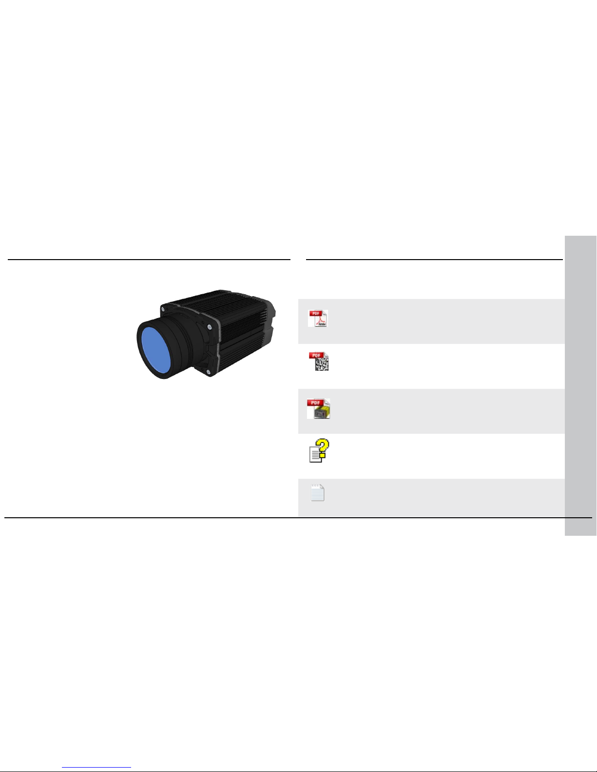
DataMan Fixed Mount Readers Reference is a complete
online hardware reference for the DataMan 300, 500, and 503.
Cognex->DataMan Software v x.x->Documentation-> <language> ->Reference Manual
4 DataMan 503 Quick Reference Guide DataMan 503 Quick Reference Guide 5
About DataMan 503
For More Information...
The DataMan 503 is a highperformance, xed-mount ID
reader that offers the following
advanced features:
• Ultra-sensitive custom image
sensor that allows short
exposures to freeze part
motion.
• High-performance processing
unit that provides extremely
short cycle times.
• Automatic regulation of
exposure time and gain
to provide maximum
performance.
• Electronically controlled
solid-state variable focus system.
• Dynamically congurable network-based multiple-reader decoding
(“master-slave”).
The DataMan 503 provides advanced Ethernet connectivity, support for
serial and discrete I/O, as well as advanced options for lighting and optics.
The DataMan 503 is packaged in a rugged, IP65-rated housing, and
it provides numerous ease-of-use features, including one-button code
training.
This document provides basic information about how to congure and
use the DataMan 503. Additional information is available through the
Windows Start menu or the Setup Tool Help menu after you install the
DataMan software on your PC:
DataMan Communications & Programming Guide shows
how to integrate your DataMan reader with your automation
software and factory network.
Cognex->DataMan Software v x.x->Documentation-> Communications &
Programming
DataMan Reader Conguration Codes provides printable
2-D codes that you can use to congure the DataMan reader.
Cognex->DataMan Software v x.x->Documentation-> <language> ->Reader
Conguration Codes
DataMan Questions and Answers provides context-sensitive
information. You can view this help inside the setup tool or as a
standalone help le.
Cognex->DataMan Software v x.x->Documentation-> <language> ->DM503->Questions
and Answers
Release Notes list detailed system requirements and additional
information about this DataMan software release.
Cognex->DataMan Software v x.x->Documentation-> DataMan v x.x.y Release Notes
Page 4
6 DataMan 503 Quick Reference Guide DataMan 503 Quick Reference Guide 7
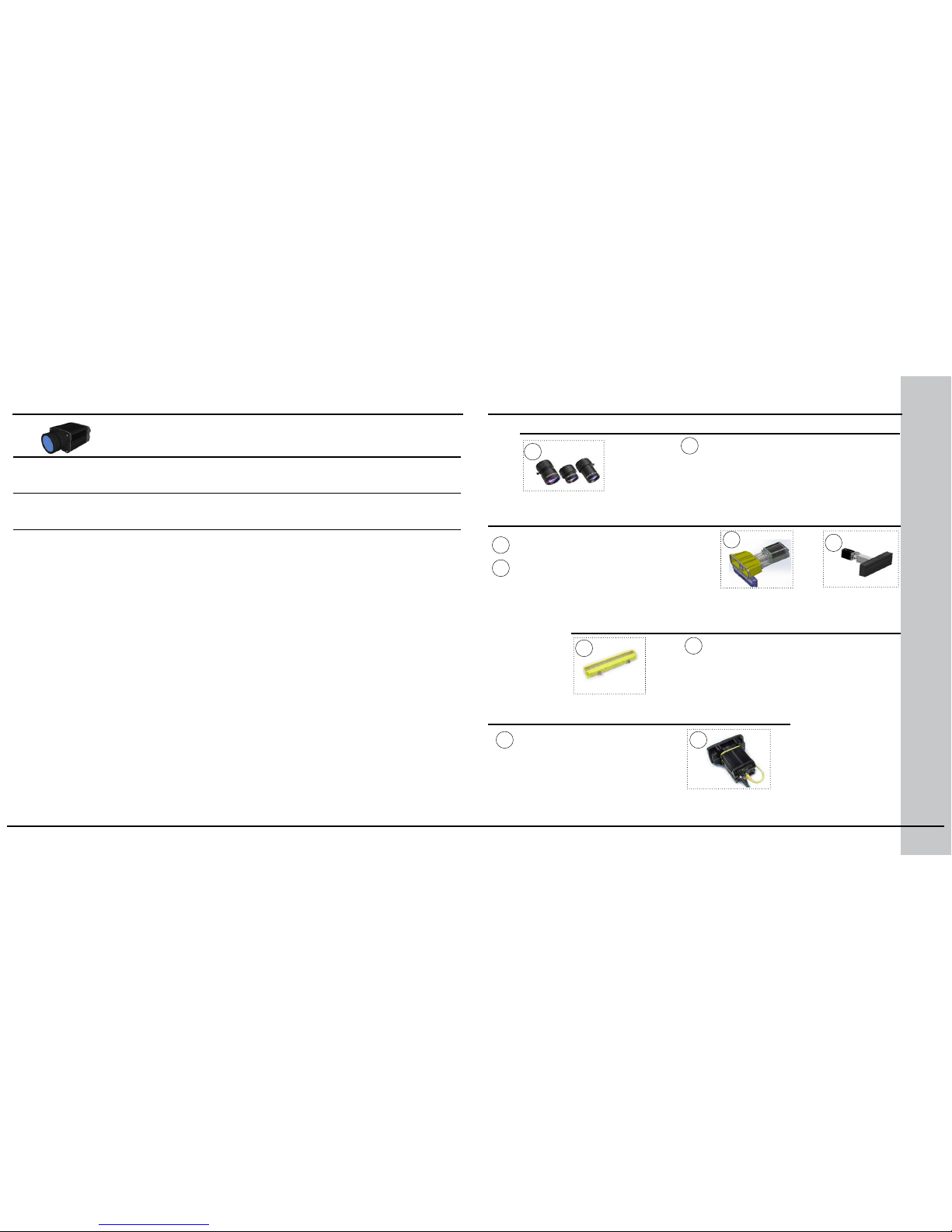
DataMan 503 Systems
High-Speed
Part Moving
Applications
Omni-
directional
Code Reading
1DMax™ —
Best-In-Class
1-D Reading
IDQuick™ —
High-Speed
2-D Reading
DataMan 503QL
(DMR-503QL-xx)
√ √ √
DataMan 503X
(DMR-503X-xx)
√ √ √ √
16 mm, 25 mm and 35 mm lens
(LEC-CFFxx-F8)
(xx species focal length)
Xpand 15 (DMA-FOVE-15)
1
1
C-MOUNT LENS OPTIONS
FIELD OF VIEW EXPANDERS
2
3
EXTERNAL LIGHT
4
HIGH POWER ILLUMINATIONS
5
(DM503-HPIA-xxx)
5
Xpand 25 (DMA-FOVE-25)
SVL Light Bar (IVSL-YLW300-xxx)
DataMan 503 Accessories
2
3
4
Page 5
8 DataMan 503 Quick Reference Guide DataMan 503 Quick Reference Guide 9
Quick Reference Guide
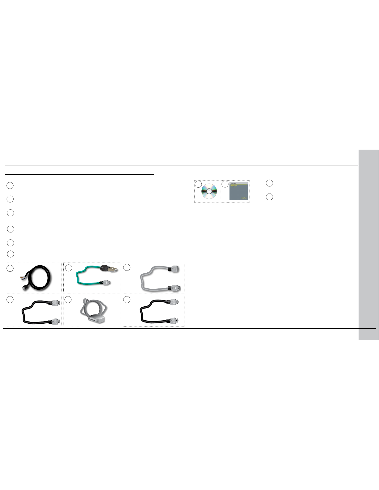
(this document) (590-7163)
Ethernet M12 to RJ45 cable (CCB-84901-y00x-xx)
(y straight/angled, x-xx species length)
Connection cable 24V, I/O (CCBL-05-01)
External light cable (CCB-M12x4MS-xxx)
(xxx species length)
6
7
8
6
7
8
CABLES
9
9
I/O extension cable, 5m straight (CKR-200-CBL-EXT)
10
RS-232 M8 to SUB-D cable (CCB-M8X4-xx)
10
Synchronization Cable (DM503-SYNC-012 - 1.2 meter, DM503-SYNC-05 - 5 meter)
11
CD-ROM, AND DOCUMENTATION
12
13
CD-ROM (Setup Tool and Drivers)
206-6400-400
12
13
DataMan 503 Accessories
11
Page 6
External illumination
mounting points
Mounting holes
(M3 x 5mm)
Tuning
button
Trigger
button
Power
Train and
trigger status
Good/
bad read
Network
Error
Ethernet
External light
control
Power,
I/O
Peak meter
RS-232
Synchronized
Acquisition
10 DataMan 503 Quick Reference Guide DataMan 503 Quick Reference Guide 11
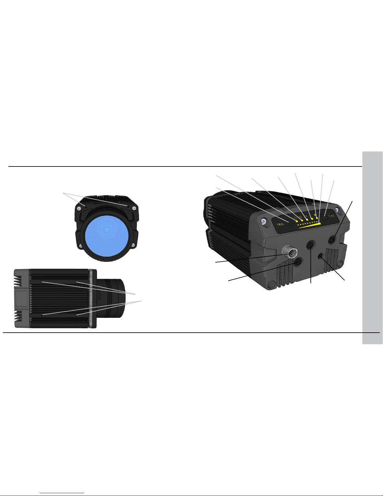
Reader Layout
The following image shows the layout of the DataMan 503 series reader.
• Power: GREEN = Power ON
• Signal: GREEN = trained / YELLOW = untrained / BLINK OFF =
trigger detected
• Good/bad read: GREEN = good read / RED = bad read
• Network: YELLOW = link up / BLINK = activity
• Error: RED = error
• Peak meter: decode yield, train progress/quality
Page 7
12 DataMan 503 Quick Reference Guide DataMan 503 Quick Reference Guide 13
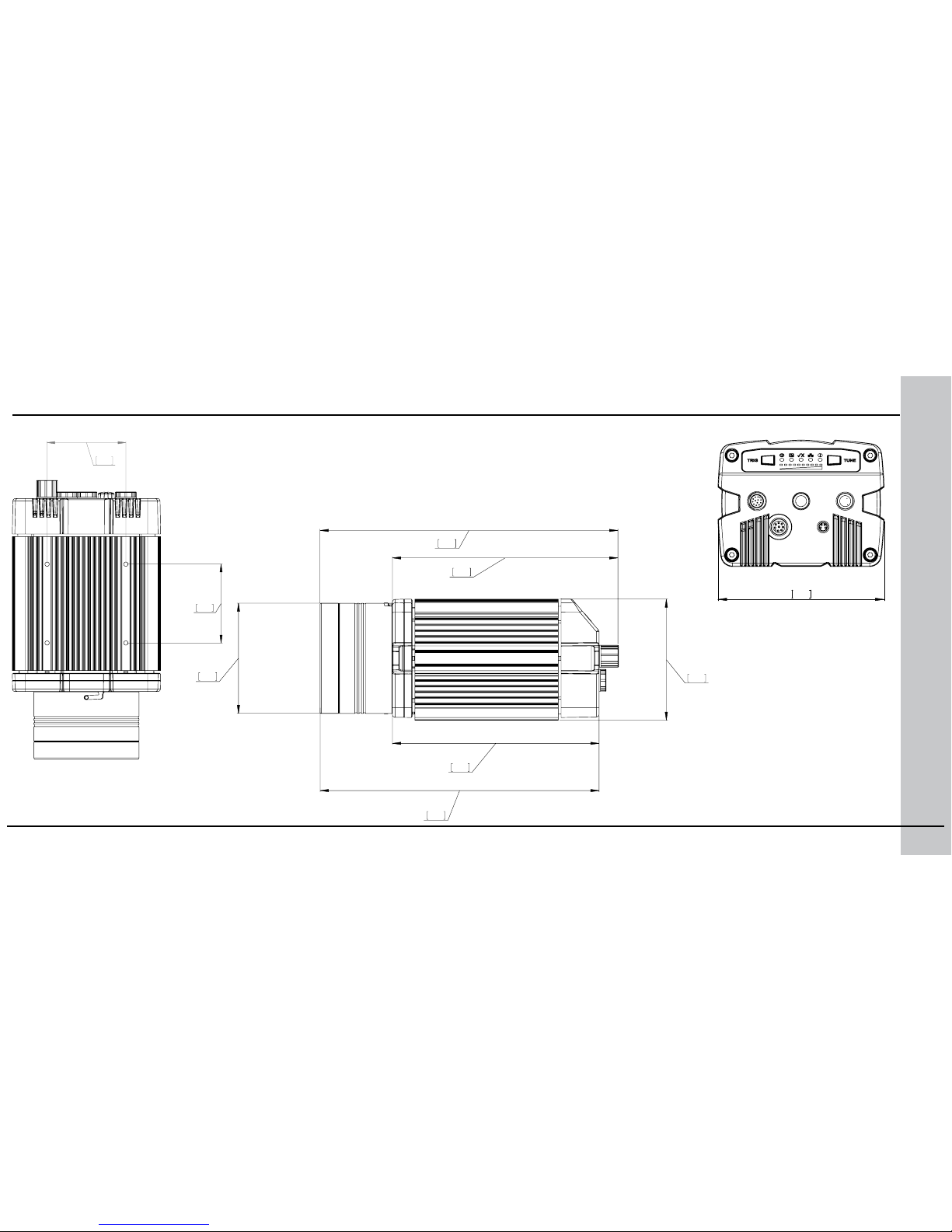
Dimensions
Observe the following DataMan 503 dimensions when installing your reader.
112.98
4.45
60
2.36
60
2.36
198.41
7.81
147
5.79
211.90
8.34
160.40
6.31
87.97
3.46
80
3.15
Page 8
14 DataMan 503 Quick Reference Guide DataMan 503 Quick Reference Guide 15
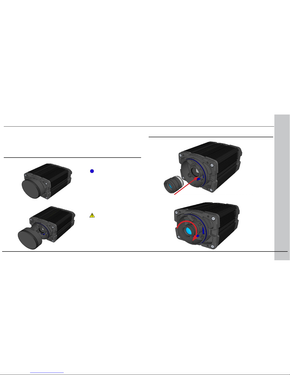
Installing the Lens
1
Unscrew the protective
cover from the lens
mount.
Remove the front cover, if attached, and lens cover.
i
Installing C-Mount Lens
Insert and thread lens into the reader.
DataMan 503 ships with no lens installed. You must install a standard C-mount
lens before using your reader.
For reading distances and eld of view charts, see the DataMan Fixed Mount
Reference, available through the Windows Start menu or the Setup Tool Help
menu.
Do not leave the DataMan
sensor exposed to the
environment!
2
Page 9
16 DataMan 503 Quick Reference Guide DataMan 503 Quick Reference Guide 17
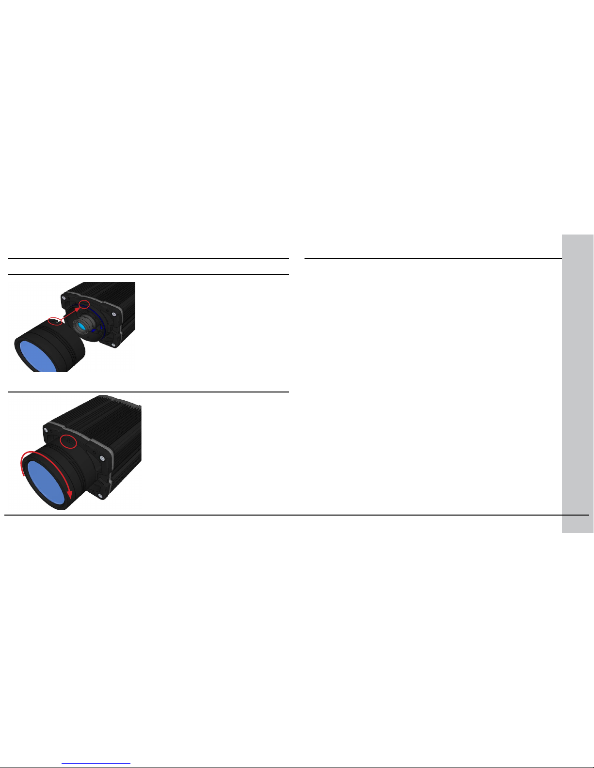
Align the peg on the reader and the slot on the cover, and re-attach it.
Installing C-Mount Lens (continued)
Lock the cover in place.
3
4
There is a range of reading distances available for different code
sizes and focus positions. To set focus on your reader, use the Focus
Feedback option on the Setup Tool’s Results Display pane.
For maximizing the performance of Focus Feedback, observe the
following:
• Use a focus target (such as the one supplied with this Quick
Reference Guide) that includes high-contrast features and is big
enough that it lls at least a 100x100 pixel region in the center of the
eld of view at the desired working distance.
• Make sure the target is perfectly at (avoid oppy pieces of paper).
• Make sure that the target is perfectly perpendicular to the optical axis
of the reader.
• Make sure that the rest of the eld of view (such as the part not
covered by the focus target) does not contain any high-contrast
features. For example, you would ideally ll the entire eld of view
with a white card or sheet of paper (no shadows), then position the
focus target in the middle.
• The supplied focus target (120x120mm) is appropriate for typical
working distances. If you are using a working distance such that the
target does not completely ll the image, make sure that there are
no high-contrast features visible outside of the target (see previous
bullet).
Setting Focus
Perform the following steps to use Focus Feedback:
1. Connect the reader to the Setup Tool.
2. On the Results Display pane, check the Focus Feedback option and
enable Live Display.
Page 10
18 DataMan 503 Quick Reference Guide DataMan 503 Quick Reference Guide 19
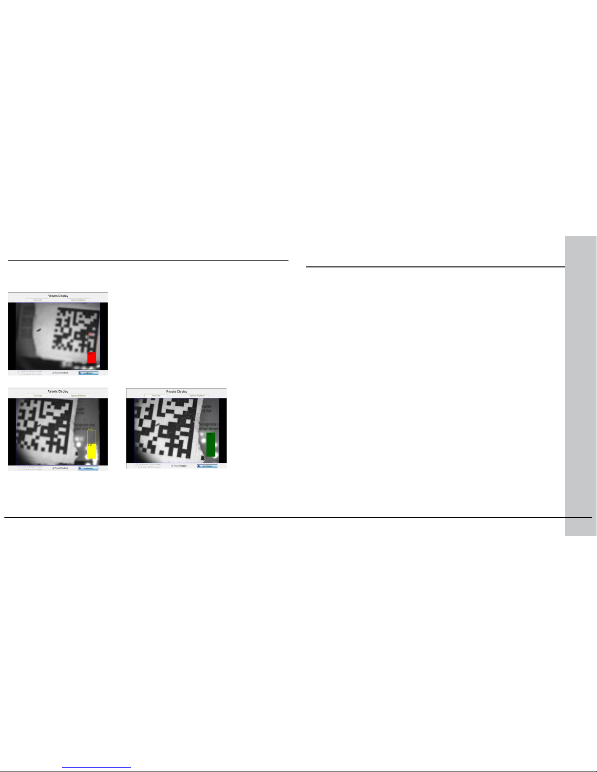
Position the reader in a way that the focus
column becomes green. This makes sure that
the lens is in focus and you will be able to
decode the image.
Setting Focus (Continued)
3. The Focus Feedback column is displayed in colors ranging from red (bad
focus) through yellow to green (sharp focus).
CONNECT YOUR READER
1. Connect the I/O+24V cable to your reader.
2. For a network connection, connect your reader, through an Ethernet
cable, to your network.
3. Connect the cable to a 24V power supply. Safety Note: Do not use
power supply with maximum current above 40A.
INSTALL DATAMAN SOFTWARE AND CONNECT
1. Check the DataMan Release Notes for a full list of system
requirements.
2. Insert CD-ROM and follow the on-screen prompts until you
successfully completed the DataMan Software installation process.
3. Connect the DataMan 503 Series reader to your PC.
4. Launch the Setup Tool and click Refresh.
Detected readers will appear under COM ports or Network devices,
or both.
5. Select a reader from the list and click Connect.
Installing DataMan Software and
Connecting the Reader
Page 11
20 DataMan 503 Quick Reference Guide DataMan 503 Quick Reference Guide 21
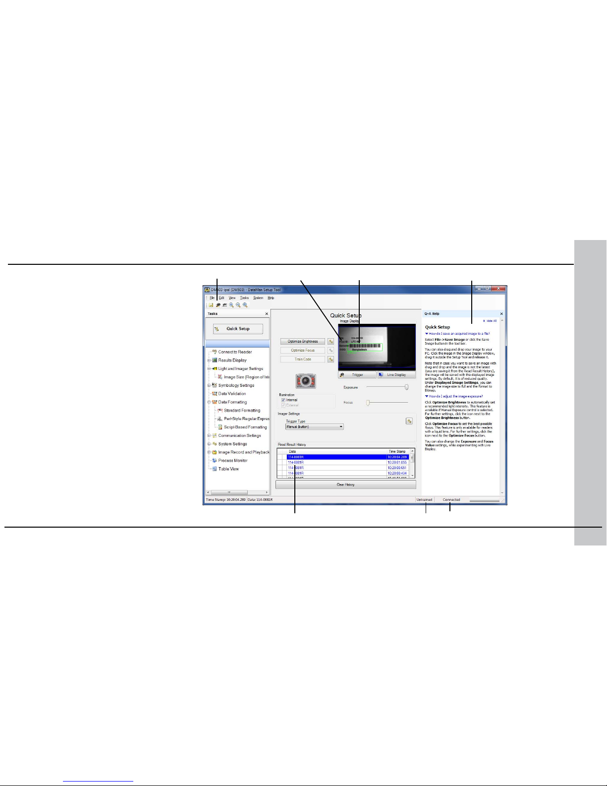
Start the Setup Tool
Quick Setup
Congure your reader in a few basic steps
Connect to Reader
Establish a connection to the reader
Results Display
View results
Light and Imager Settings
Choose a trigger type and other acquisition
parameters
System Settings
Congure input and output signals
Table View
See all the selectable values in the Setup Tool
in one table
Trigger button
Read history
Connect the reader to the Setup Tool to
congure it with the type of symbologies
it will decode as well as other parameters,
such as the type of trigger it will use and the
format of the results it will generate.
Region of interest Latest image
Context based help
Train status Connection status
Page 12
22 DataMan 503 Quick Reference Guide DataMan 503 Quick Reference Guide 23
Troubleshooting an Ethernet Connection
Based on your network conguration, the Setup Tool may not be able to
communicate with the reader and it will not appear in the list of Network
devices.
First check your Ethernet connection with the reader and click Refresh in the
Setup Tool. Next, scan the Enable DHCP code in the Reader Conguration
Codes document available from the Start menu. This might allow the reader to
acquire a suitable IP address from a DHCP server on your subnet.
If the reader still does not appear, you can use either the Add Device or
Force Network Settings options in the Setup Tool.
If you know the IP address of the reader, use the Add Device option. If you
do not know the IP address, use the Force Network Settings options. Either
method should allow the DataMan 503 reader to appear in the list of Network
devices so that you can connect to it through the Setup Tool and your
Ethernet connection.
You can also use the RS-232 connection to congure the reader with
parameters that allow it to communicate over your Ethernet network.
Industrial Protocols
The DataMan 503 series readers support the following industrial
protocols:
• EtherNet/IP™
• PROFINET
• MC Protocol
• Modbus TCP
There are three ways to enable or disable Industrial Protocols. Using
either method, a reboot is required for the changes to come into effect.
• Enable the protocols using the Industrial Protocols pane of the
Setup Tool (under Communication Settings).
• Scan the appropriate Reader Conguration codes (see Reader
Conguration Codes available through the Windows Start menu or
the Setup Tool Help menu).
• Send the appropriate DMCC (see Command Reference available
through the Windows Start menu or the Setup Tool Help menu).
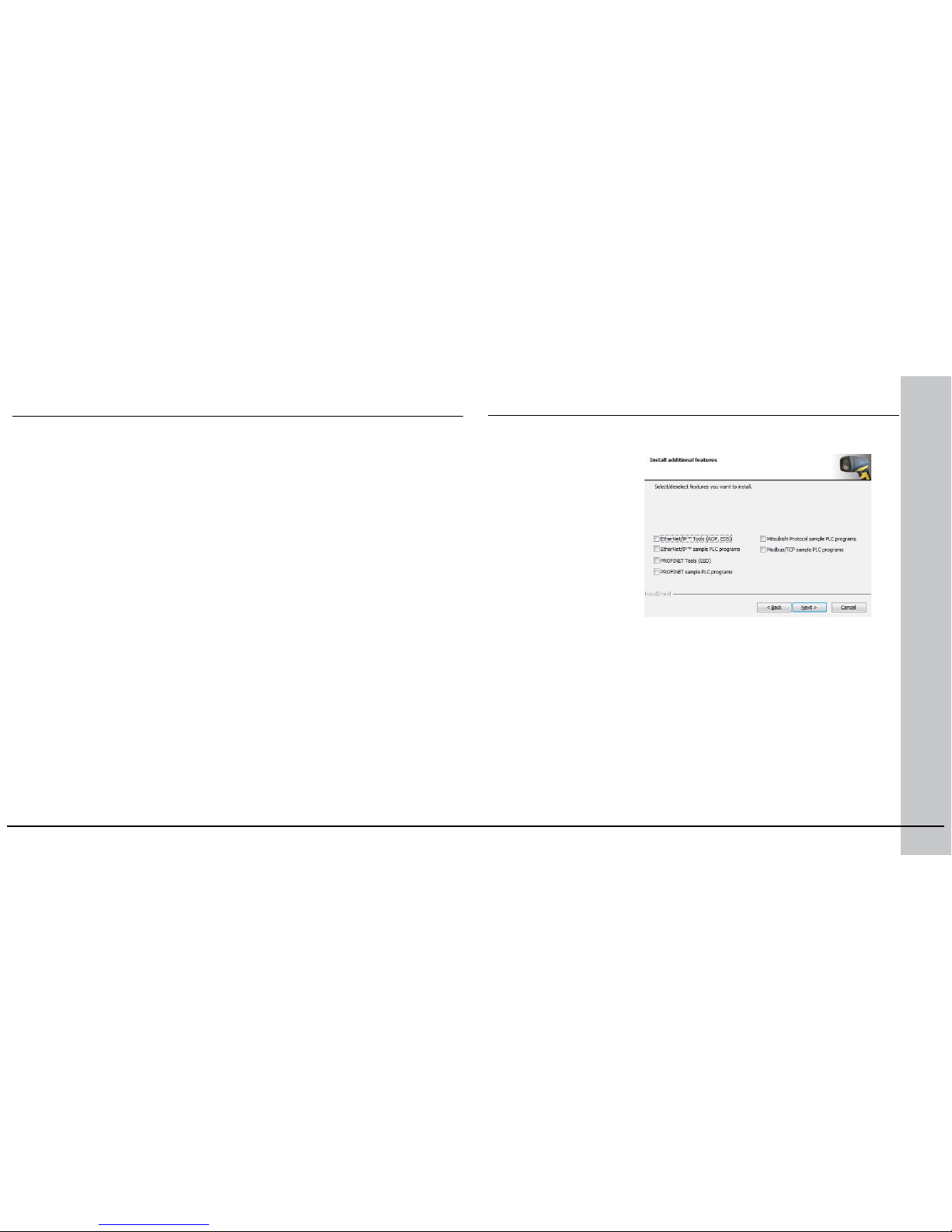
Select industrial
protocol samples and
tools you want to use
when you install the
DataMan Software.
For more information on using the industrial protocols, read the
DataMan Communications and Programming Guide available through
the Windows Start menu or the Setup Tool Help menu.
Page 13
24 DataMan 503 Quick Reference Guide DataMan 503 Quick Reference Guide 25
Use the Setup Tool Menu Bar
The In1 button on the toolbar creates a virtual rising edge signal on Input
1. Use the In1 button to activate various actions such as training a code,
optimizing brightness or setting a match string without a physical input 1
channel.
Each reader can store its current set of runtime parameters to a conguration
(.cfg) le, which contains information such as the enabled symbologies and
how any output data should be formatted.
The same conguration le can be loaded onto multiple readers, as the le
does not contain identication information such as the IP address or device
name of the reader used to create it.
A reader can also generate a Cognex device conguration (.cdc) le, which
stores the set of runtime parameters plus any identication data, such as
the name of the device, its IP address, subnet mask, and so on. Cognex
recommends generating a device conguration le for each reader to allow you
to restore a reader to its operating state with minimal effort.
Use the File menu of the Setup Tool to manage .cfg and .cdc les, export
parameters, or to load, save, or train uploaded images.
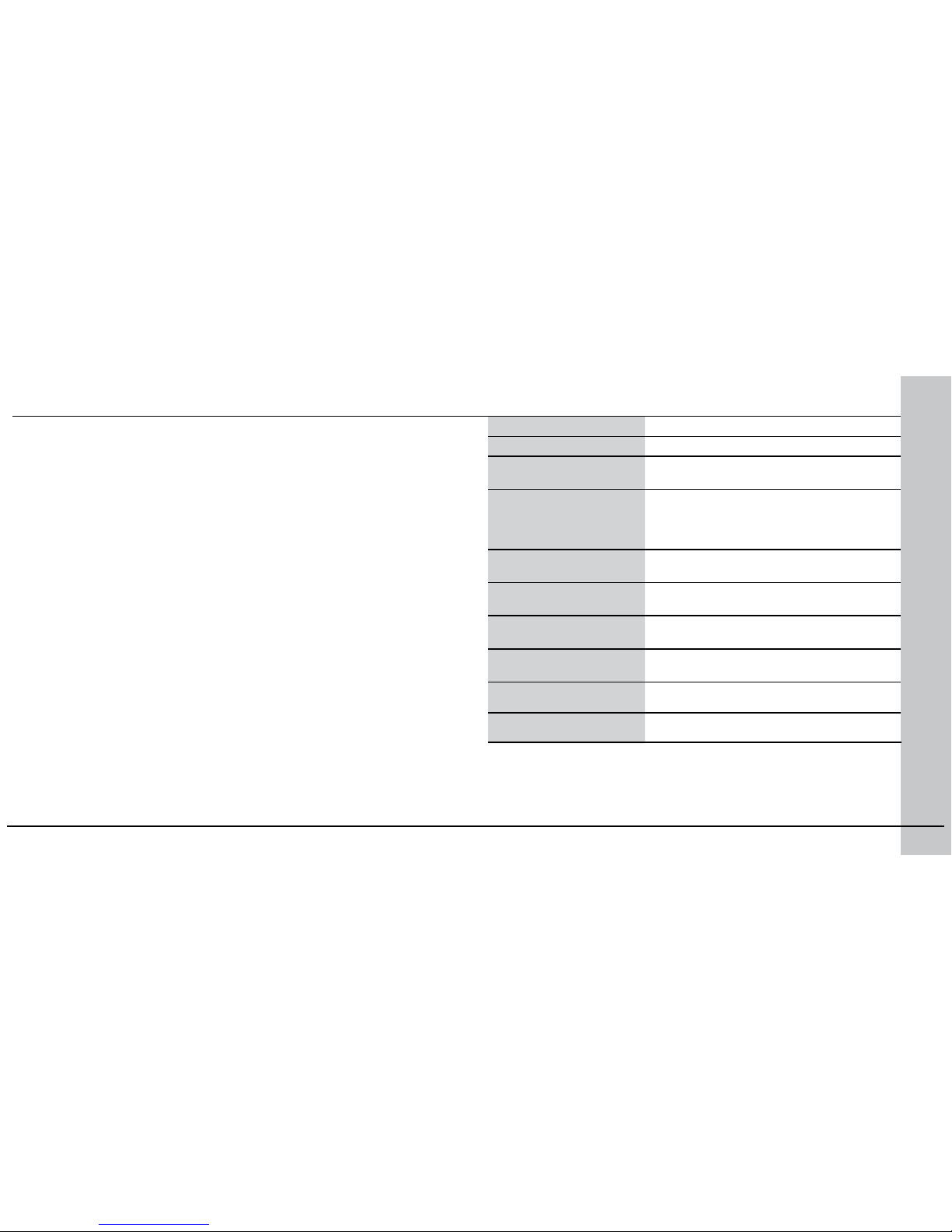
File Menu
Open Conguration Open a saved .cfg conguration le.
Save Conguration Create a .cfg conguration le of current
runtime parameters.
Restore Device Load a saved device conguration .cdc
le, with run-time parameters plus
device-specic information for a particular
DataMan 503 reader.
Backup Device Create a device conguration .cdc le for a
specic reader.
Export Parameters Save (all or only the non-default)
parameters of your device in a text le.
Load Image Load an 8-bit uncompressed grey-scale
.bmp or .jpg image for analysis.
Save Image Save the latest acquired image with the
.jpg or .bmp le format.
Save Burst Images Save the latest batch of burst images.
Train Image Upload an image to be used for training.
Page 14
26 DataMan 503 Quick Reference Guide DataMan 503 Quick Reference Guide 27
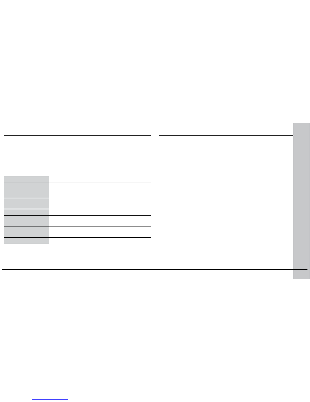
System Menu
Save Settings Save the current parameters to non-volatile memory,
which allows the reader to restore these settings
each time you reboot it.
Reset Conguration Reset all conguration parameters in RAM (volatile
memory) to the default settings.
Update Firmware Update the reader software.
Upload Feature Key Unlock additional features available in the reader
software if you have the right key.
Show Device Log Error and exception conditions, such as missed
triggers and trigger overruns are logged.
Delete Device Log Clear your device log.
Use the Help menu to display Setup Tool version information.
Use the Setup Tool Menu Bar (Continued)
Use the Edit menu for standard Cut, Copy and Paste operations.
Use the View menu to view reader information (serial number, rmware
version, and so on) and to enable and disable various elements of the Setup
Tool, and the Tasks menu to switch between various Setup Tool options.
Use the System menu to manage the current settings on the reader and to
upgrade the features it currently supports:
DataMan 503 Triggering
DataMan 503 supports self-triggered operation. In self-trigger mode,
at an interval you congure, the reader automatically detects and
decodes codes in its eld of view. The high-speed image acquisition
and processing capabilities of the DataMan 503 allow it to detect and
decode codes at up to 80 codes per second, multiple decodes per scan.
If you set a higher re-read delay than the trigger interval, there is a code
output only once until the code is out of the eld of view for the duration
of the re-read delay.
DataMan 503 also supports these additional trigger modes:
• Single (external trigger): Acquires a single image and attempts to
decode any symbol it contains, or more than one symbol in cases
where multicode is enabled. The reader relies on an external trigger
source.
• Presentation: Scans, decodes and reports a single code in the eld of
view. The reader relies on an internal timing mechanism to acquire
images.
• Manual: Begins acquiring images when you press the trigger button
on the reader, and continues acquiring images until a symbol is found
and decoded or you release the button.
• Burst: Performs multiple image acquisitions based on an external
trigger and decodes any symbol appearing in a single image or within
a sequence of images, or multiple symbols in a single image or within
a sequence of images when multicode is enabled. You can control the
number of images within each burst and the interval between image
acquisitions.
• Continuous: Begins acquiring images based on a single external
trigger and continues to acquire and decode images until a symbol
is found and decoded, or until multiple images containing as many
codes as specied in multicode mode are located, or until the trigger
Page 15
28 DataMan 503 Quick Reference Guide DataMan 503 Quick Reference Guide 29
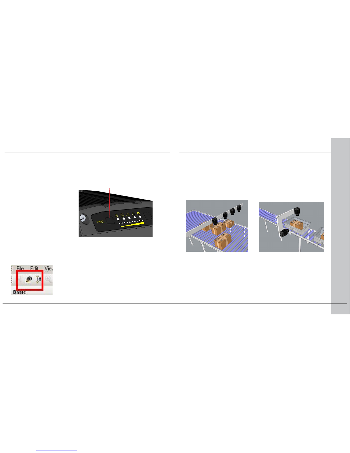
• Press the trigger button on
the reader.
• Send a pulse on the I/O cable:
• Trigger + (red/blue)
• Trigger - (white)
• Send a trigger command over
the RS-232 connection or
Ethernet connection.
• Press <CTRL>-T on the
keyboard.
• Click the Trigger button in the
Setup Tool:
If you are using external triggering you can use any of these methods to
trigger DataMan 503:
is released. You can congure your reader to acquire images based on the start
and stop signal from separate digital IO pulses.
DataMan 503 Triggering (Continued)
Multi-Reader Triggering
For trigger modes other than Presentation, the DataMan 503 supports
multi-reader triggering, also known as master-slave conguration. In
this conguration, you congure multiple DataMan 503 readers as a
group. Whenever any reader in the group is triggered, all the readers
are triggered and the results from all the readers are assembled and
transmitted by a single reader that you designate as the master.
Multi-reader triggering is used to support extended eld of view reading
and reading codes from multiple product surfaces:
To congure multi-reader triggering, select the Master/Slave pane in
the Setup Tool (under System Settings). For more information, see
the DataMan Fixed Mount Readers Reference.
Page 16
30 DataMan 503 Quick Reference Guide DataMan 503 Quick Reference Guide 31
Synchronized Acquisition
In Single, Burst, Continuous, and Self trigger modes, it is possible to
synchronize image acquisition on multiple devices using the synchronization
interface.
Synchronization allows using one shared strobed illumination to expose all
sensors simultaneously. You can synchronize up to 16 readers, with optionally
triggering them in a dened sequence to avoid that opposing readers blind
each other.
Note that this and other imager settings will not get synchronized by this
mechanism - for example, you must congure exposure and gain on each
reader individually.
This feature only synchronizes the actual image acquisition, triggering happens
through the existing master-slave mechanism.
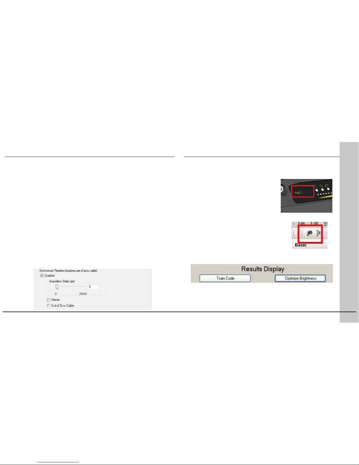
Enable Synchronized Exposure on the Setup Tool’s Master/Slave pane.
Set the Acquisition Delay (µs) (relative to the received signal through the
synchronization interface) on each reader individually to optionally dene an
exposure sequence in case the illumination of some readers might affect other
readers.
You must also set which two readers on the ends of the synchronization
interface bus are bus terminators by checking the End of Sync Cable
checkbox for the currently connected devices at the end of a sync cable.
Training the Reader
Training your reader with the expected symbology can decrease the
time required to decode successive symbols. To train your reader, rst
switch to Single mode, then place a code in front of the reader and do
one of the following:
• Press and hold the trigger button for a
minimum of 3 seconds.
• Click and hold the trigger button in
the Setup Tool for a minimum of 3
seconds.
• Click Train Code in the Results Display pane.
You can now switch to Burst, Continuous or Self trigger modes if
necessary. NOTE that only a single symbol of each symbology kind can
be trained.
• Upload the code through File menu Train Image.
Page 17
32 DataMan 503 Quick Reference Guide DataMan 503 Quick Reference Guide 33
Training Feedback
The middle LED on the reader glows green to indicate that it is currently
trained, or yellow to indicate that it is not trained.
Connect the reader to the Setup Tool to untrain it and allow it to recognize
other enabled symbologies.
Incremental Training for Multiple Symbologies
If you want to train the reader to recognize multiple symbologies, you can
present a single image showing all the desired symbologies and perform the
training procedure previously described.
If you cannot present a single image showing all the necessary symbologies,
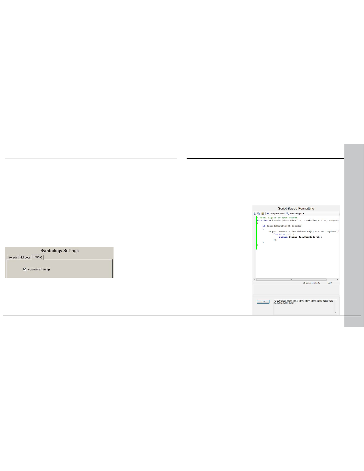
you can enable incremental training on the Training tab of the Symbology
Settings pane:
With incremental training enabled, you can train the reader using multiple
images showing the symbologies you expect to decode. The reader will train
each new symbology while retaining the existing trained symbologies.
Script-Based Data Formatting
In addition to standard formatting possibilities, you have the option to
write a script inside the Setup Tool. When script-based formatting is
enabled, you can dene a JavaScript module to format data according
to your needs.
The script not only allows you to have different data formatting
combinations, but you can also perform operations on the output
channel, for example, to pull output 1 up. You can congure read results
exibly and congure reader events before the result returns.
Enter your script on the
Script-Based Formatting
pane under Data Formatting.
For the details of how
to write the script and
for scripting examples,
please see the DataMan
Communications and
Programming Guide. You can
nd scripting samples in the
right-click context menu of
the Script-Based Formatting
pane.
You can open your own
scripts through the Setup
Tool’s File menu Open
Script... option.
Training the Reader (Continued)
Page 18
34 DataMan 503 Quick Reference Guide DataMan 503 Quick Reference Guide 35
Package Detection Support
You can connect your package detection sensor to one of the digital inputs
of your DataMan reader. When the reader receives a signal that a package is
detected, images that the reader collected are not discarded at the end of the
trigger. This way you can make sure that there was a package there, only the
code was not readable. Looking at the No Read images will help you nd out
why there was no decode results.
Package detection is only supported with Continuous trigger mode.
To make sure that the No Read images are collected, perform the following:
1. Connect your package detection device to one of the Inputs of your reader.
2. On the Setup Tool’s System Settings pane’s Inputs tab, check Allow
Buffered No-Read Images on the input you connected your reader to.
3. On the Setup Tool’s Image Record and Playback pane, change What
Images to Buffer to All, or No Read.
• In case of All, good reads are also saved together with No Reads.
• In case of No Read the image is buffered if the reader fails to read.
For more information, see the DataMan Fixed Mount Readers Reference,
available through the Windows Start menu or the Setup Tool Help menu.
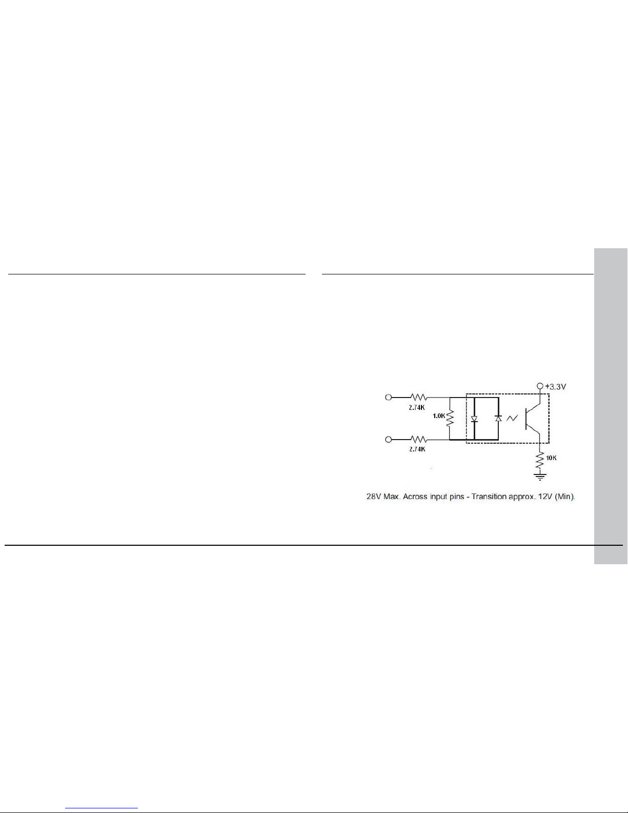
The acquisition trigger input on the reader is opto-isolated. To trigger
from an NPN (pull-down) type photo-detector or PLC output, connect
In 0 to +24V and connect Common In to the output of the detector.
When the output turns on, it pulls Common In down to 0V, turning the
opto-coupler on.
To trigger from an PNP (pull-up) photo-detector or PLC output, connect
In 0 to the output of the detector and connect Common In to 0V.
When the output turns on, it pulls In 0 up to 24V, turning the optocoupler ON.
In 0
Common In
Acquisition Triggering
Page 19
36 DataMan 503 Quick Reference Guide DataMan 503 Quick Reference Guide 37
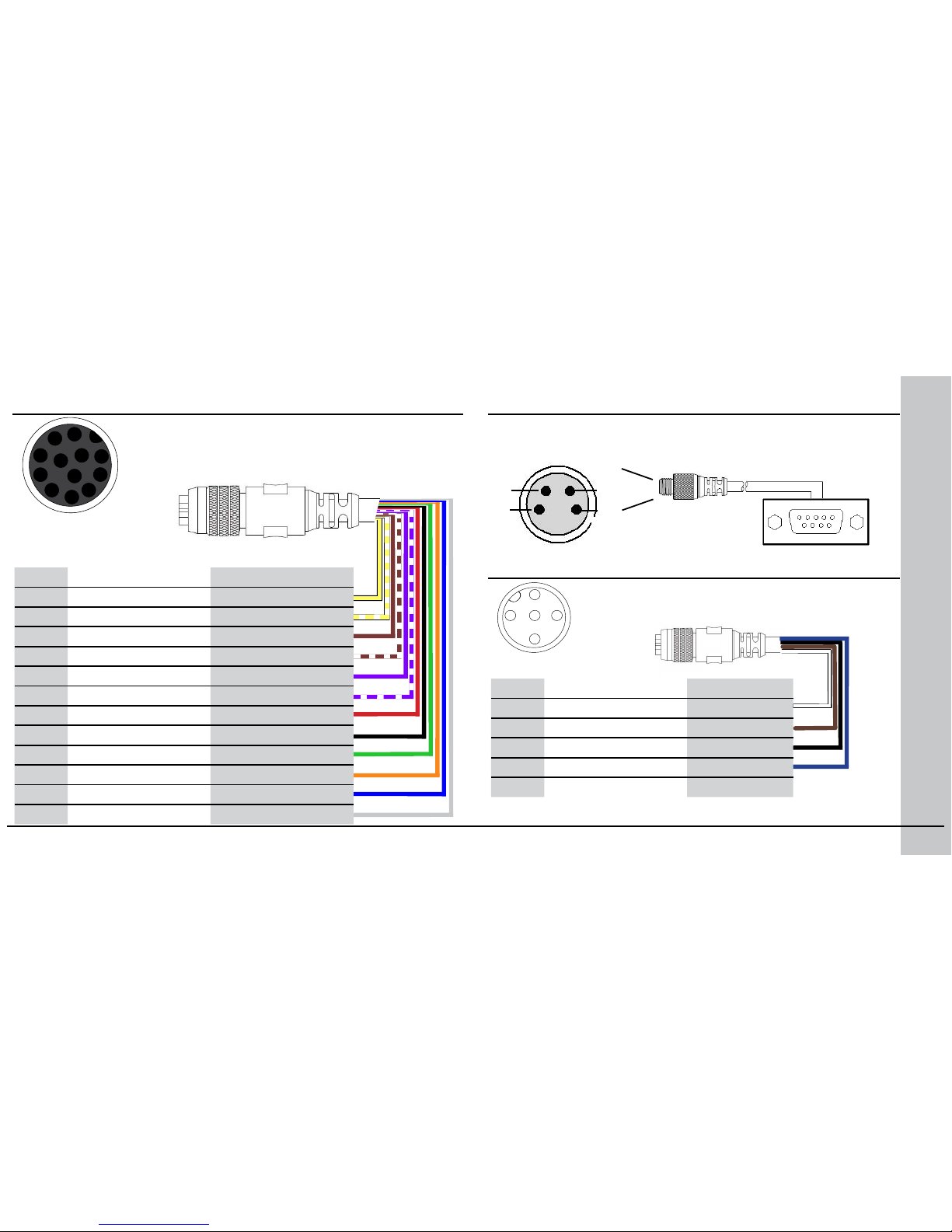
I/O Cable
The I/O cable provides access to trigger and high-speed
outputs. Unused wires can be clipped short or tied back
using a tie made of non-conductive material.
RS-232 Cable
The RS-232 cable provides an optional connection between the reader
and your PC.
2
4
RxD
3
GND
TxD
1
3
RxD
2
TxD
5
GND
2
3
5
External Light Control
A 4-pin cable is provided for the external light control.
1
2
3
4
5
Current load: average: 500mA, peak: 1A (max. 100µs).
NOTE that this socket does not work if the external light is connected to
one of the outputs on the I/O cable.
Pin # Signal Name Wire Color
1 +24 VDC white
2 Brightness Control brown
3 GND black
4 Strobe blue
5 Chassis not connected
Pin # Signal Name Wire Color
1 Out 2 Yellow
2 In 3 White/Yellow
3 In 2 Brown
4 Out 3 White/Brown
5 In 1 Violet
6 Common In White/Violet
7 +24 VDC Red
8 GND Black
9 Common Out Green
10 In 0 Orange
11 Out 0 Blue
12 Out 1 Gray
The above drawing shows
the plug on the device.
10
12
1
9
8
7
6
5
11
4
3
2
Page 20
38 DataMan 503 Quick Reference Guide DataMan 503 Quick Reference Guide 39
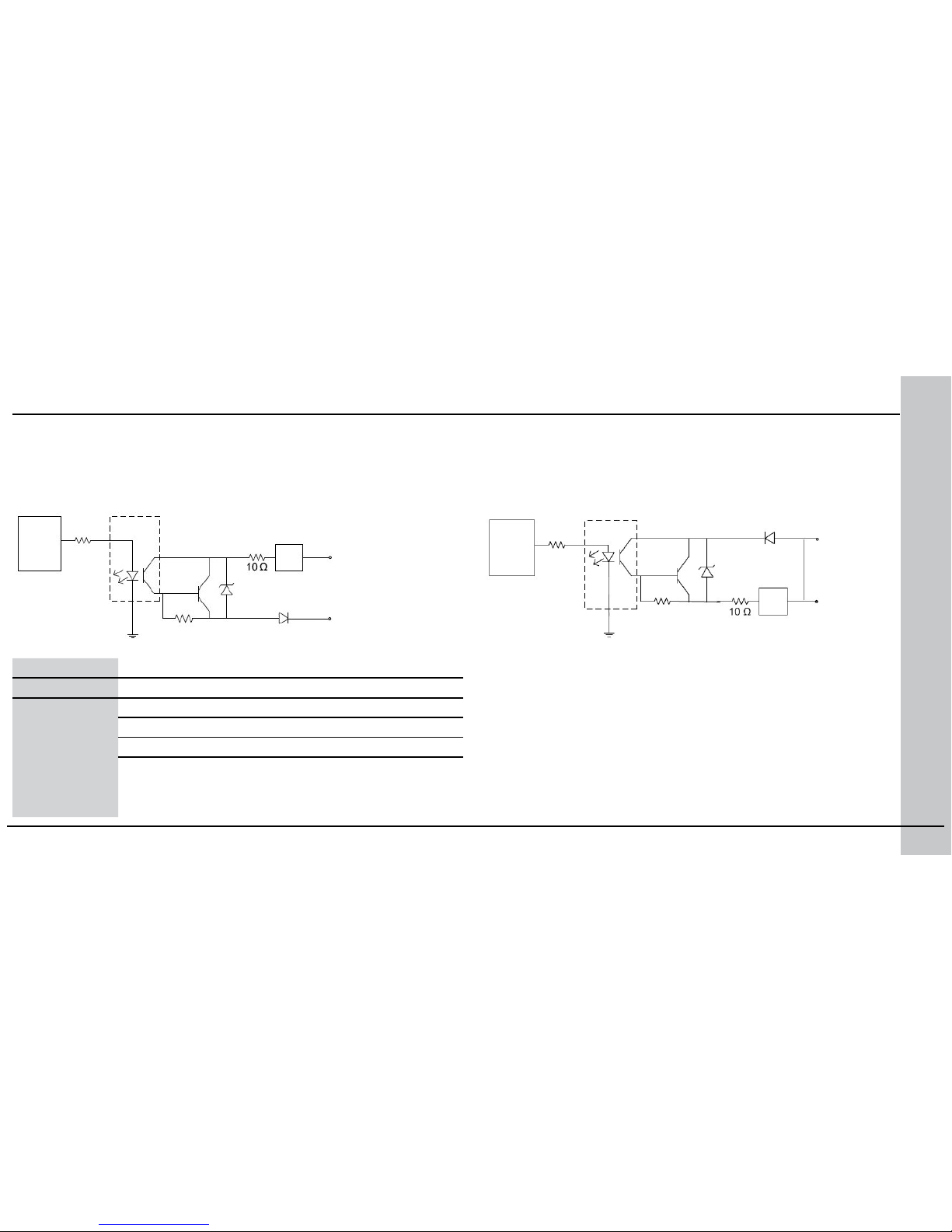
High-Speed Output Lines
The high-speed outputs can be used as either NPN (pull-down) or PNP (pull-up)
lines. For NPN lines, the external load should be connected between the output
and the positive supply voltage (<28V). The outputs pull down to less than 3V
when ON, which causes current to ow through the load. When the outputs are
OFF, no current ows through the load.
Controller
Opto-isolators
NPN Out
Out Common
Specification Description
Voltage 28V maximum through external load
Current 50mA maximum sink current
OFF state leakage current 100µA
External load resistance 240 Ohms to 10K Ohms
Each line rated at a maximum 50mA, protected against
over-current, short circuits and transients from switching
inductive loads. High current inductive loads require
external protection diode.
PTC
Fuse
For PNP lines, the external load should be connected between the output
and the negative supply voltage (0V). When connected to a 24VDC
power supply, the outputs pull up greater than 21V when ON, and
current ows through the load. When the outputs are OFF, no current
ows through the load.
Out
Common
PNP Out
Controller
Opto-isolators
PTC
Fuse
Page 21
40 DataMan 503 Quick Reference Guide DataMan 503 Quick Reference Guide 41
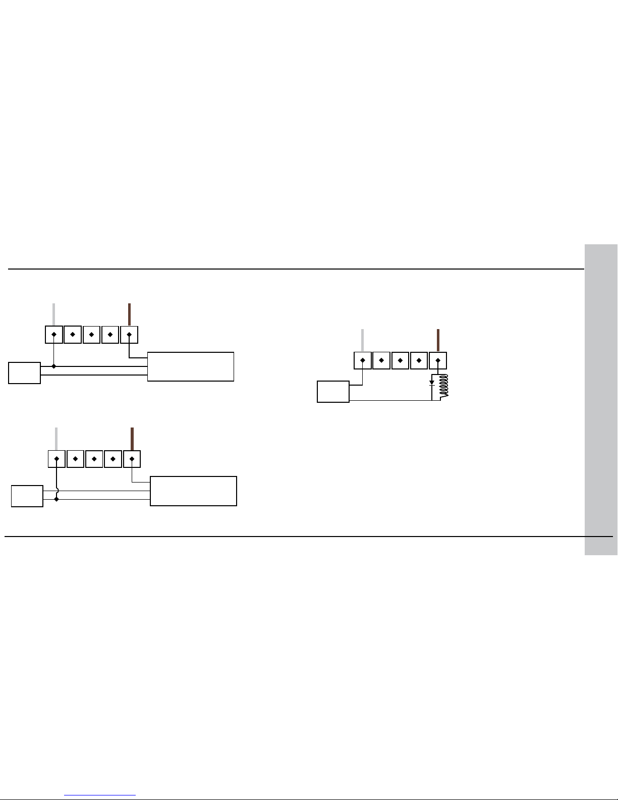
High Speed Output Wiring
To connect to an NPN-compatible PLC input, connect Output 0 or Output 1
directly to the PLC input. When enabled, the output pulls the PLC input down to
less than 3V.
GND
24VDC
Common
High Speed Out 0
NPN PLC
NPN Compatible Input
GND
24VDC
To connect to a PNP-compatible PLC input, connect Output 0 or Output 1
directly to the PLC input. When enabled, the output pulls the PLC input up to
greater than 21V.
GND
24VDC
Common
High Speed Out 0
PNP PLC
PNP Compatible Input
GND
24VDC
GND
24VDC
Common
Load
(Coil, Relay...)
Not to exceed
50mA
High Speed Out 0
To connect the high-speed outputs to a relay, LED or similar load,
connect the negative side of the load to the output and the positive side
to +24V. When the output switches on, the negative side of the load
is pulled down to less than 3V, and 24 appears across the load. Use a
protection diode for a large inductive load, with the anode connected to
the output and the cathode connected to +24V.
Page 22
42 DataMan 503 Quick Reference Guide DataMan 503 Quick Reference Guide 43
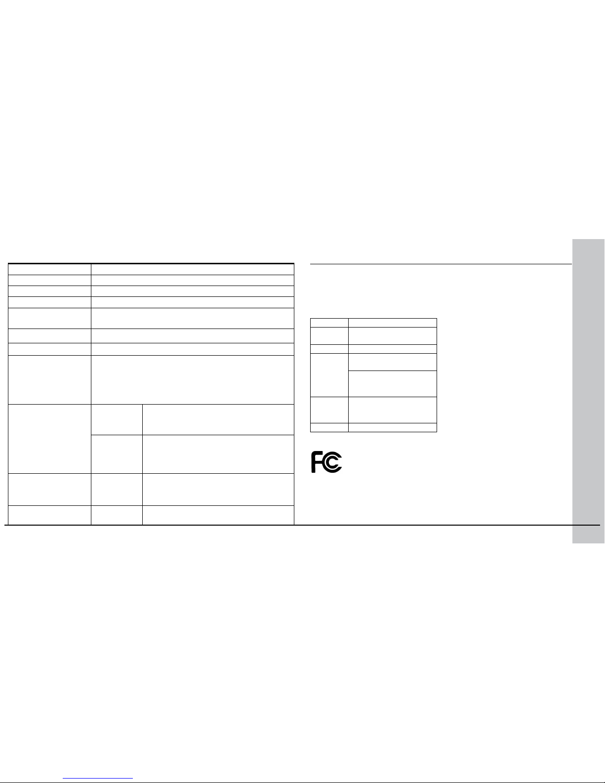
Weight 1602 g
Operating Temperature 0ºC — 45ºC (32ºF — 113ºF)
Storage Temperature -10ºC — 60ºC (-14ºF — 140ºF)
Maximum Humidity 95% (non-condensing)
Environmental IP65 (with cable or protection cap attached to all connectors, front cover
properly installed)
Vibration IEC 60068-2-6,60068-2-27
RS-232 RxD, TxD according to TIA/EIA-232-F
Codes
Data Matrix
TM
(IDMax: ECC 0, 50, 80, 100, 140, and 200; IDQuick:
ECC200)
QR Code and microQR Code, MaxiCode
UPC/EAN/JAN
Codabar, Interleaved 2 of 5, Code 39, Code 128, and Code 93, Pharma,
Postal, RSS/CS, PDF 417, MicroPDF 417
Discrete I/O operating
limits
HS Output
0,1
I
MAX @ 24 VDC 50 mA
RMAX @ 12 VDC 150 Ω
@ 24 VDC 470 Ω
Input 0 (Trigger)
Input 1
V
IH ±12 — ±28 V
VIL 0 — ±7 V
ITYP @ 12 VDC 2.0 mA
@ 24 VDC 4.2 mA
Power Supply Requirements
24V +/- 10%
Maximum current: 500 mA (at 25ºC)
Maximum power: 18W (external lights)
Light Connector Current load Average: 500mA
Peak: 1A (max. 100µs)
DataMan 503 Specications
The DataMan 503 series meets or exceeds the requirements of all appli-
cable standards organizations for safe operation. However, as with any
electrical equipment, the best way to ensure safe operation is to operate
them according to the agency guidelines that follow. Please read these
guidelines carefully before using your device.
Regulator Specication
USA FCC Part 15, Subpart B,
Class B
Canada ICES-003, Class B
European
Community
EN55022:2006 +A1:2007,
Class B
EN55024:1998 +A1:2001
+A2: 2003
EN60950
Australia C-TICK, AS/NZS CISPR 22 /
EN 55022 for Class B Equip-
ment
Japan J55022, Class B
FCC Class B Compliance Statement
This equipment has been tested and found to comply with the limits
for a Class B digital device, pursuant to Part 15 of the FCC rules. These
limits are designed to provide reasonable protection against harmful
interference when the equipment is operated in a commercial environment. This equipment generates, uses, and can radiate radio frequency
Compliance Statements
Page 23
44 DataMan 503 Quick Reference Guide DataMan 503 Quick Reference Guide 45
Cognex Corporation shall not be liable for use of our product with equipment (i.e., power supplies, personal computers, etc.) that is not CE
marked and does not comply with the Low Voltage Directive.
For European Community Users
Cognex complies with Directive 2002/96/EC OF THE EUROPEAN PARLIAMENT AND OF THE COUNCIL of 27 January 2003 on waste electrical and
electronic equipment (WEEE).
This product has required the extraction and use of natural resources for
its production. It may contain hazardous substances that could impact
health and the environment, if not properly disposed.
In order to avoid the dissemination of those substances in our environment and to diminish the pressure on the natural resources, we encourage you to use the appropriate take-back systems for product disposal.
Those systems will reuse or recycle most of the materials of the product
you are disposing in a sound way.
The crossed out wheeled bin symbol informs you that the
product should not be disposed of along with municipal
waste and invites you to use the appropriate separate
take-back systems for product disposal.
If you need more information on the collection, reuse, and recycling systems, please contact your local or regional waste administration.
You may also contact your supplier for more information on the environmental performance of this product.
Compliance Statements (Continued)
energy and, if not installed and used in accordance with the instructions, may
cause harmful interference to radio communications. Operation of this equipment in a residential area is likely to cause harmful interference, in which case
the user will be required to correct the interference at personal expense.
Canadian Compliance
This Class B digital apparatus complies with Canadian ICES-003.
Cet appareil numérique de la classe B est conforme à la norme NMB-003 du
Canada.
C-Tick Statement
Conforms to AS/NZS CISPR 22/ EN 55022 for Class B Equipment.
European Compliance
The CE mark on the product indicates that the system has been tested to and
conforms to the provisions noted within the 2004/108/EEC Electromagnetic
Compatibility Directive and the 2006/95/EEC Low Voltage Directive.
For further information please contact:
Cognex Corporation
One Vision Drive
Natick, MA 01760
USA
Page 24
46 DataMan 503 Quick Reference Guide DataMan 503 Quick Reference Guide 47
Warnings and Notices
CAUTION: IP protection is ensured only when all connectors are attached
to cables or shielded by a sealing cap.
FAILURE TO FOLLOW THESE INSTRUCTIONS MAY CAUSE
SERIOUS INJURY
• Do not attempt to service or repair this product -- return it to Cognex
for service.
• Do not permit anyone other than Cognex Corporation to service,
repair, or adjust this product.
• Do not attempt to open or modify this device except as described in
this document.
• Do not operate this device if it is damaged or if the covers or seals
are missing or damaged.
For assistance contact Cognex Corporation at http://support.cognex.com
Page 25
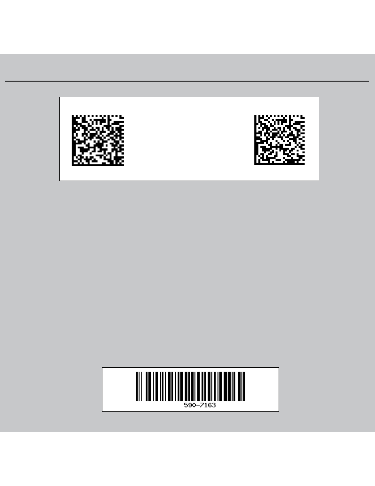
Reset Scanner to
Factory Defaults
Reboot Scanner
Reader Control Codes
P/N 590-7163
Copyright © 2013 Cognex Corporation All Rights Reserved. This document may not be
copied in whole or in part, nor transferred to any other media or language, without the
written permission of Cognex Corporation. The hardware and portions of the software
described in this document may be covered by one or more of the U.S. patents listed
on the Cognex web site http://www.cognex.com/patents.asp. Other U.S. and foreign
patents are pending. Cognex, the Cognex logo, and DataMan are trademarks, or
registered trademarks, of Cognex Corporation.
Reset Scanner to
Factory Defaults
Reboot Scanner
 Loading...