

Page 1
DataMan
®
50
Quick Reference Guide
04/18/2017
Version: 5.7.0.102
Page 2

Precautions
Observe these precautions when installing the Cognex product, to reduce the risk of
injury or equipment damage:
l To reduce the risk of damage or malfunction due to over-voltage, line noise,
electrostatic discharge (ESD), power surges, or other irregularities in the
power supply, route all cables and wires away from high-voltage power
sources.
l Changes or modifications not expressly approved by the party responsible
for regulatory compliance could void the user’s authority to operate the
equipment.
l Cable shielding can be degraded or cables can be damaged or wear out
more quickly if a service loop or bend radius is tighter than 10X the cable
diameter. The bend radius must begin at least six inches from the
connector.
l This device should be used in accordance with the instructions in this
manual.
l Allspecifications are for reference purpose only and may be changed
without notice.
2
Page 3
Product Overview
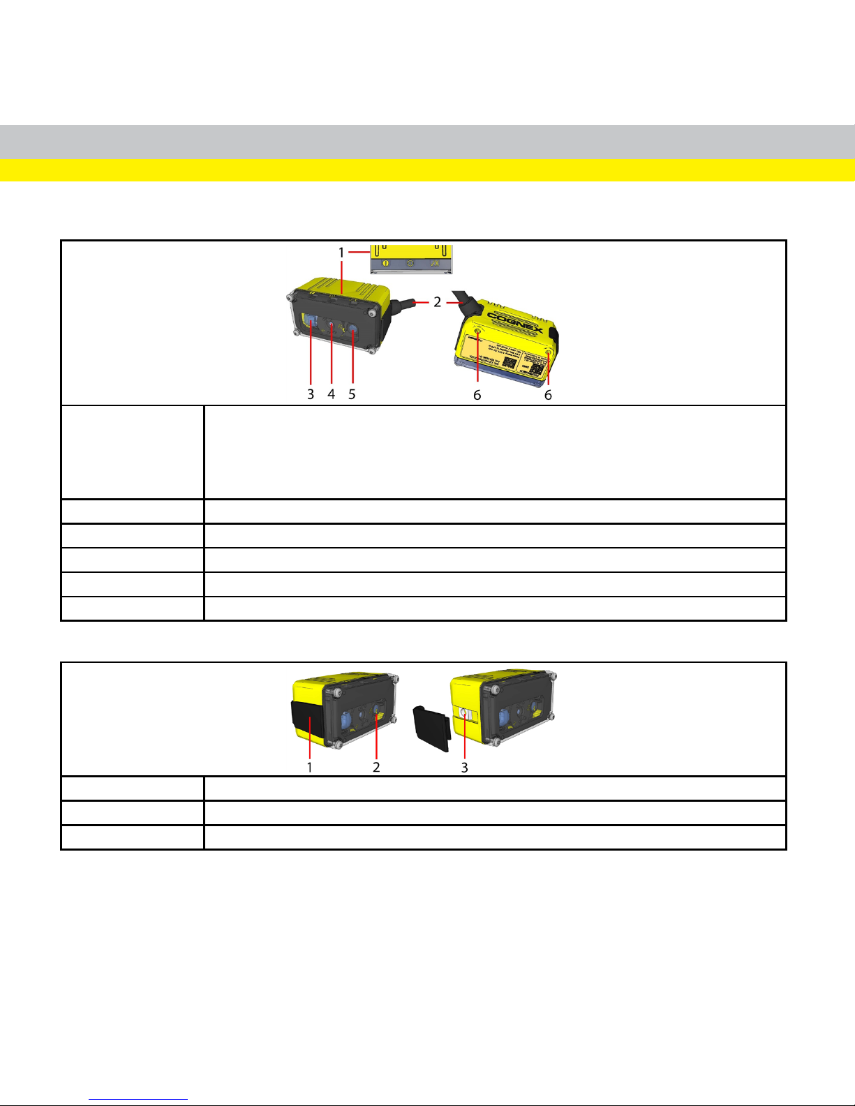
1 Status LEDs:
- Power: YELLOW = Power ON
- Communication: Flashing YELLOW
- Good / bad read: GREEN = good read / RED = bad read
- Error: RED = error, check device log
2 Cable
3
Internal illumination
4
3-position M12 lens
5 LED aimer
6 Mounting holes (M3 x 3.5 mm)
1 Remove side cover to access square nut (M3)
2 Yellow arrow indicates selected focus position
3 Hidden square nut as an alternative mounting option
3
Page 4
DataMan 50 Accessories
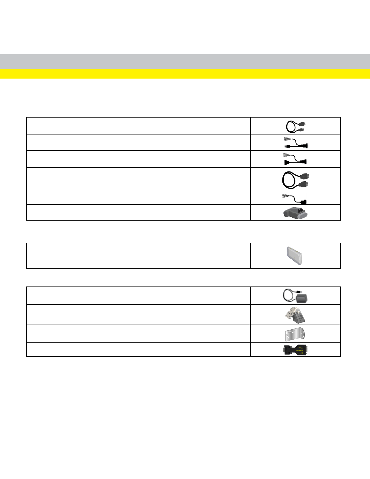
CABLES
USB Cable, 1.5 m (DM100-USB-000),
USB Cable, 3 m (DM100-USB-030)
USB and Flying Leads I/O Cable, 2.0 m (DM-USBIO-00)
RS-232 and Flying Leads I/O Cable, 2.5 m (DM-RS232IO-00)
RS-232 Cable, 1.5 m (DM100-RS232-000),
Extension Cable, 5 m (DM100-EXTCBL-000)
Flying Leads Connection Cable, 5 m (DM50-PWRIO-05)
RS-232/USB adapter connector (DM100-PATCH-000)
LENS COVERS
Clear Front Cover (DM-50-CLCOV)
ESD-safe Front Cover (DM50-CLCOV-ESD)
OTHER
Power Supply, 6 V (DM100-PWR-000)
Pivot Mounting Bracket (DM100-PIVOTM-00)
Universal Mounting Bracket (DM50-UBRK-000)
Control Box (DM-CTRLBOX-00)
4
Page 5
Dimensions
5
Page 6
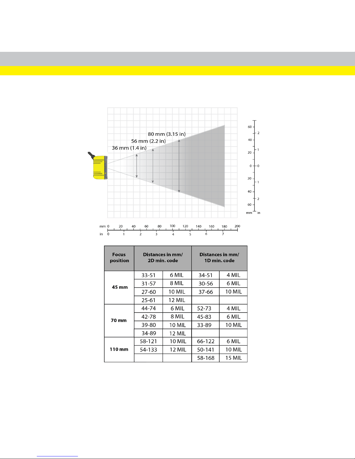
Field of View and Reading Distances
6
Page 7
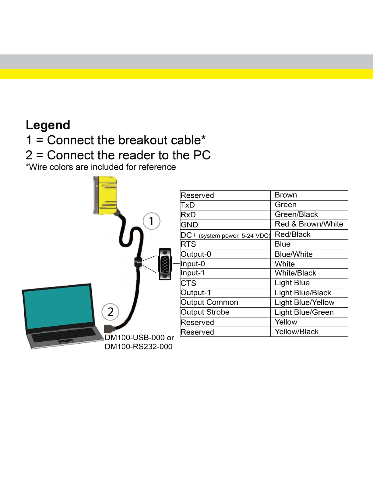
Connecting the Reader
7
Page 8
Installation
Installation procedures and specifications are presented in detail in the DataMan®50
Reference Manual, which is installed with the DataMan Setup Tool. From the
Windows Start menu, select the following to access the manual: All Programs >
Cognex > DataMan Software vx.x.x > Documentation.
Note:
l Cables are sold separately.
l If any of the standard components appear to be missing or damaged,
immediately contact your Cognex Authorized Service Provider (ASP)
or Cognex Technical Support.
CAUTION: Allcable connectors are “keyed” to fit the connectors on the
reader; do not force the connections or damage may occur.
Mounting
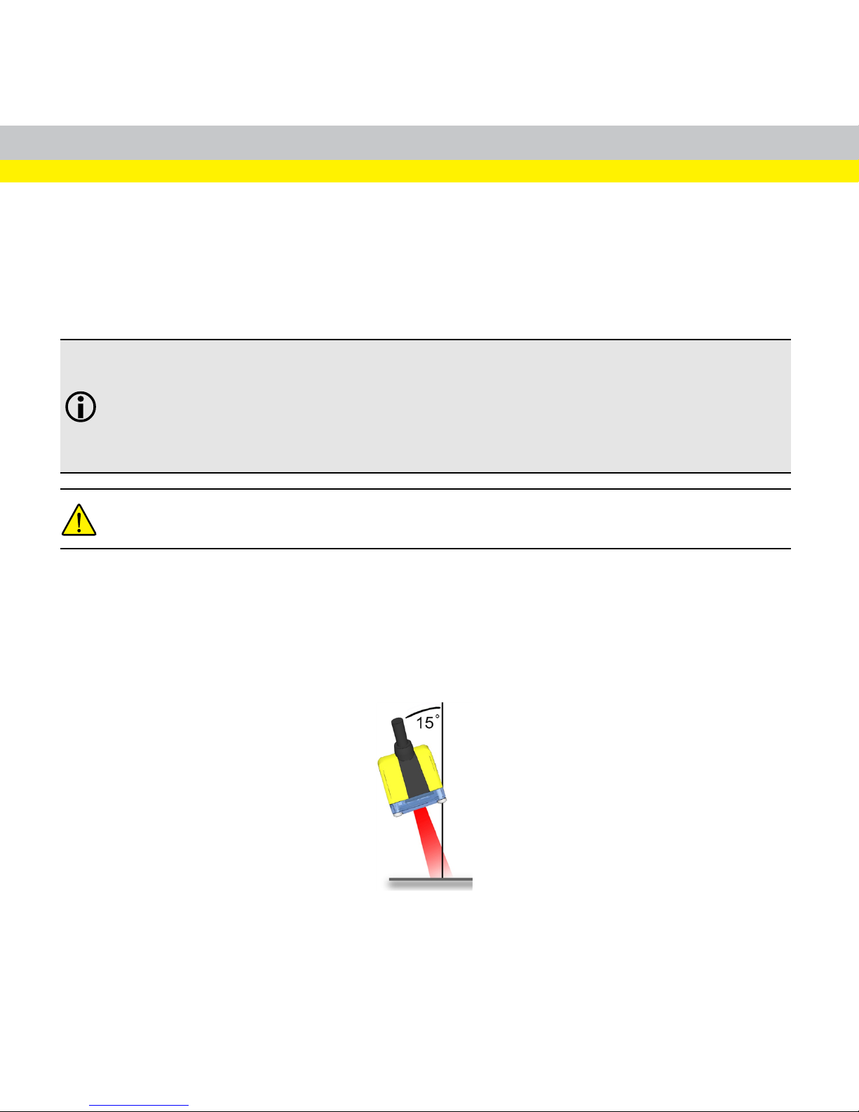
Mounting the DataMan reader at a slight angle (15°) can reduce reflections and
improve performance.
Use the set of mounting holes on the rear part to mount the DataMan reader.
8
Page 9
Connect the Breakout Cable
Note: Unused wires can be clipped short or tied back using a tie made of non-
conductive material. For RS-232, use the Power Supply return path for
ground.
1. Verify that the power supply being used is unplugged and not receiving
power.
2. Connect the cable on the back of the device to either a USB adapter cable
with power tab or to an RS-232 adapter cable with power tab.
3. Connect a 6 V power supply.
4. Restore power to the power supply and turn it on if necessary.
9
Page 10

Install Software and Documentation and
Connect the Reader
Follow the steps below to connect your reader to power and network:
1. Connect the USB or RS-232 cable to your reader.
2. Connect the cable to a power supply.
To configure a DataMan 50 reader, the DataMan Setup Tool software must be
installed on a networked PC. The DataMan Setup Tool is available from the
DataMan support site: http://www.cognex.com/support/dataman.
1. After installing the software, connect the DataMan 50 reader to your PC.
2. Launch the DataMan Setup Tool and click Refresh.
3. Select your DataMan 50 reader from the list and click Connect.
10
Page 11
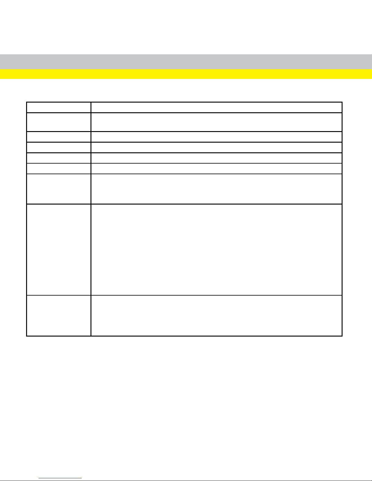
DataMan 50 Specifications
Weight
76 g
(including cable)
Operating
Temperature
0 ºC — 40 ºC (32 ºF — 104 ºF)
Storage Temperature -10 ºC — 60 ºC (-14 ºF — 140 ºF)
Maximum Humidity 95% (non-condensing)
Environmental
IP65 if sealing is installed properly
LED Safety IEC 62471: Exempt risk group, no further labeling is required.
Codes
1-D barcodes: Codabar, Code 39, Code 128, and Code 93, Interleaved 2 of 5, Pharma,
Postal, UPC/EAN/JAN
2-D barcodes: Data Matrix™
QR Code and microQR Code, MaxiCode, RSS/CS, PDF 417, MicroPDF 417
Discrete I/O
Operating Limits
Output 0,1
I
MAX
@ 24 VDC 25 mA
V
MAX
26
V
Output 2
Source V
TYP
4 V
Sink V
IH
4 V - V
PSU
V
IL
0 — 2 V
Input 0 (Trigger)
Input 1
V
IH
4 — 26 V
V
IL
0 — 2 V
I
TYP
3 mA
Power Supply
Requirements
V
PSU
4,5 — 26 VDC
2.5 W maximum
LPS or NEC class 2 power supply
11
Page 12
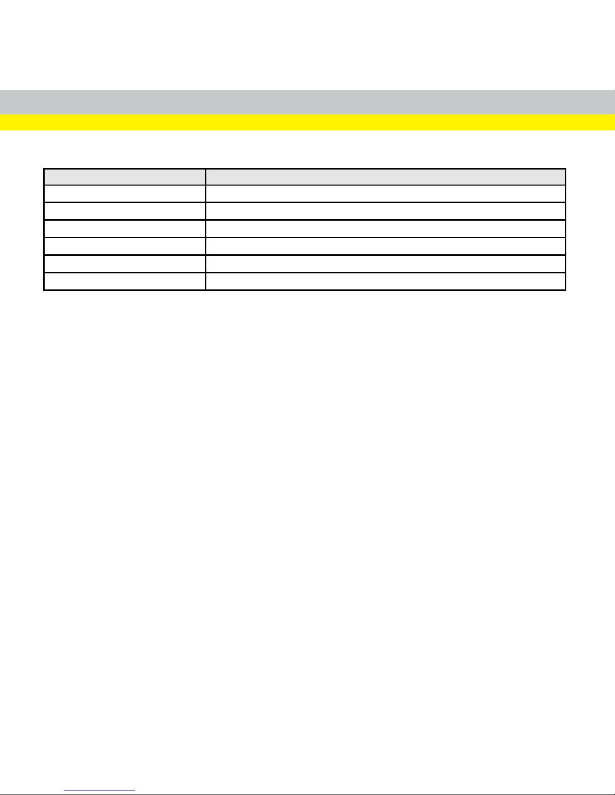
DataMan 50 Imager Specifications
Specification DataMan 50 Series Imager
Image Sensor 1/3 inch CMOS
Image Sensor Properties 4.51 mm x 2.88 mm (H x V), 6.0 µm square pixels
Image Resolution (pixels) 752 x 480
Electronic Shutter Speed 18 µs to 25 ms exposure
Image Acquisition up to 60 fps at full resolution
Lens Type 6.2 mm, F:5,3 focal position M12 lens with IR blocking filter
12
Page 13
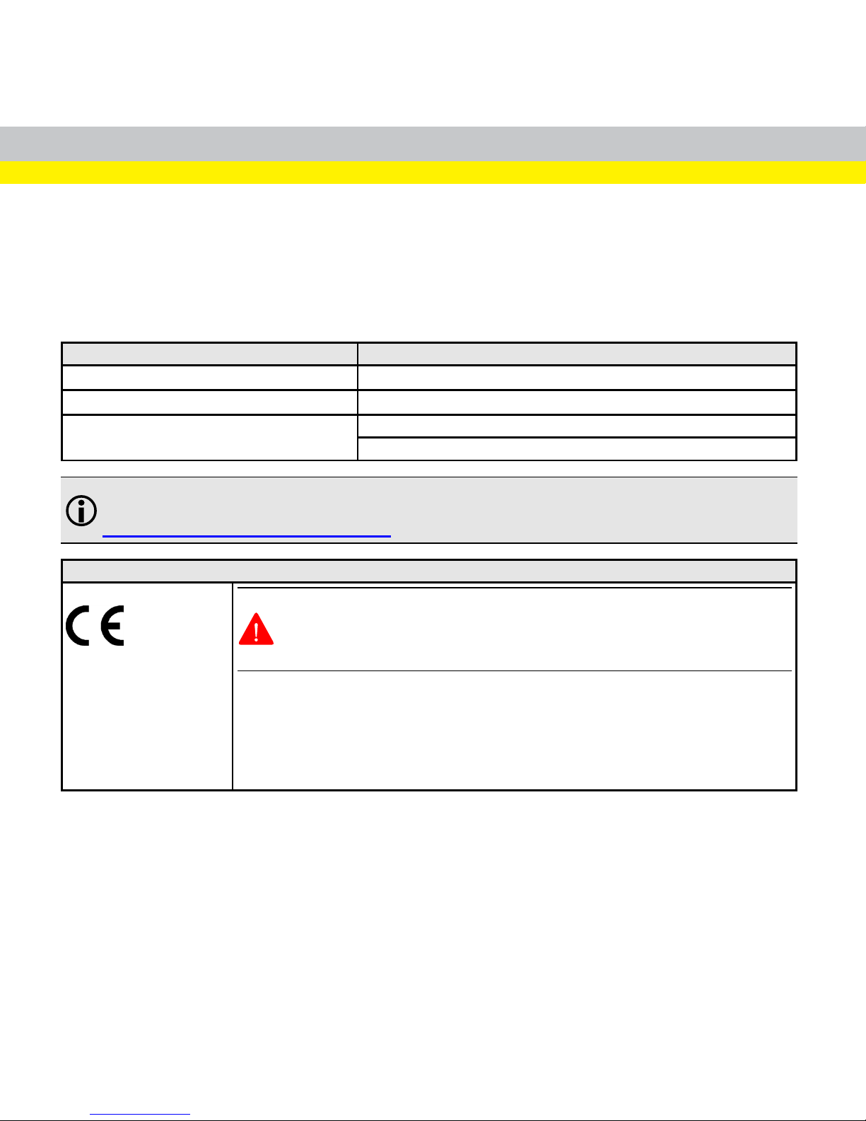
Compliance Statements
DataMan 50 readers meet or exceed the requirements of all applicable standards
organizations for safe operation. However, as with any electrical equipment, the best
way to ensure safe operation isto operate them according to the agency guidelines
that follow. Please read these guidelines carefullybefore using your device.
Regulator Specification
USA
FCC Part 15, Subpart B, Class A
Canada ICES-003, Class A
European Community
EN55022, Class A
EN55024
Note: For the most up-to-date CE declaration and regulatory conformity
information, please refer to the Cognex online support site:
http://www.cognex.com/Support.
Safety and Regulatory
European Compliance
WARNING: This is a class A product. In a domestic environment this product
may cause radio interference in which case the user may be required to take
adequate measures.
The CE mark on the product indicates that the system has been tested to and conforms
with the provisions noted within the 2014/30/EU Electromagnetic Compatibility. For
further information please contact: Cognex Corporation, One Vision Drive Natick, MA
01760 USA.
Cognex Corporation shall not be liable for use of our product with equipment (i.e.,
power supplies, personal computers, etc.) that is not CE marked.
13
Page 14
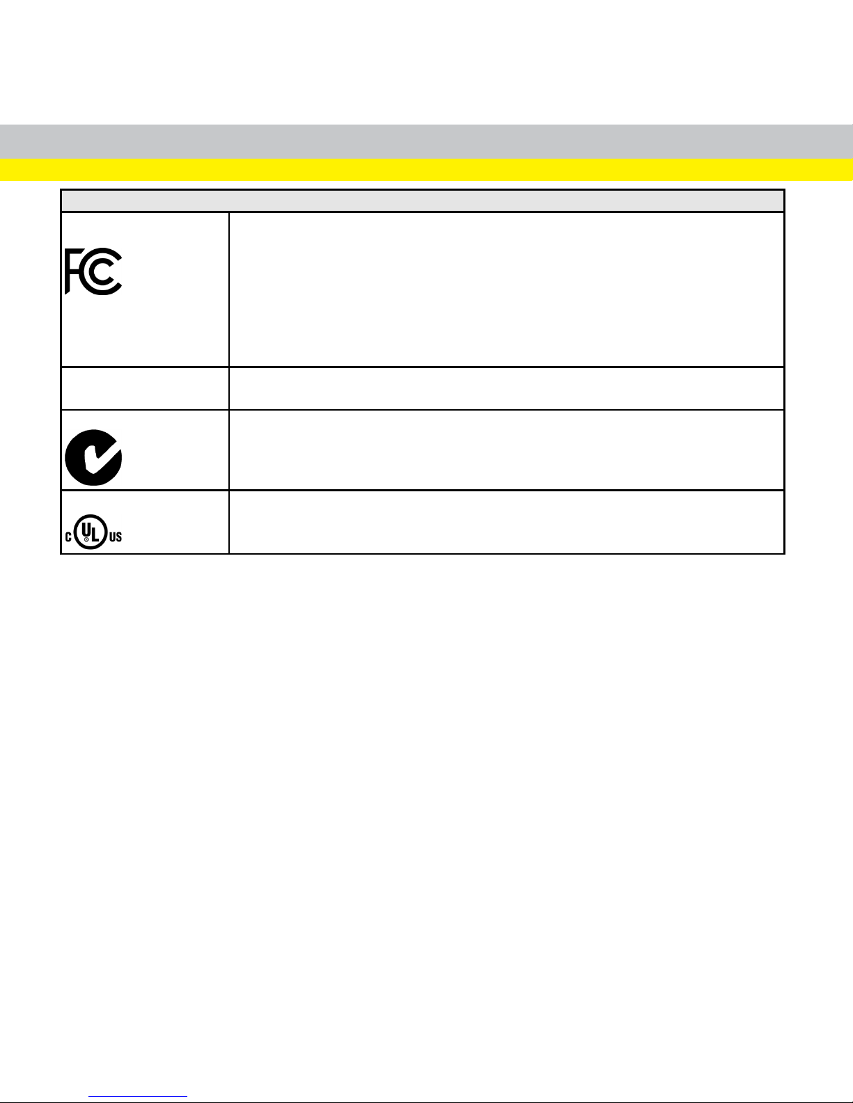
Safety and Regulatory
FCC Class A
Compliance Statement
This equipment has been tested and found to comply with the limits for a Class A digital
device, pursuant to Part 15 of the FCC rules. These limits are designed to provide
reasonable protection against harmful interference when the equipment is operated in
commercial environment. This equipment generates, uses, and can radiate radio
frequency energy and, if not installed and used in accordance with the instructions, may
cause harmful interference to radio communications. Operation of this equipment in a
residential area is likely to cause harmful interference, in which case the user will be
required to correct the interference at personal expense.
Canadian Compliance
This Class A digital apparatus complies with Canadian ICES-003. Cet appareil
numérique de la classe A est conforme à la norme NMB-003 du Canada.
C-Tick Statement
Conforms to AS/NZS CISPR 22/ EN 55022 for Class A Equipment.
UL and cUL Statement
IEC 60950-1:2005 (2nd Edition); Am 1:2009
LED Safety Statement
This device has been tested in accordance with IEC62471, and has been certified to
be under the limits of Exempt Risk Group. No further labeling is required.
For European Community Users
Cognex complies with Directive 2012/19/EU OF THE EUROPEAN PARLIAMENT
AND OF THE COUNCIL of 4 July 2012 on waste electrical and electronic equipment
(WEEE).
This product has required the extraction and use of natural resources for its
production. It may contain hazardous substances that could impact health and the
environment, if not properly disposed.
14
Page 15
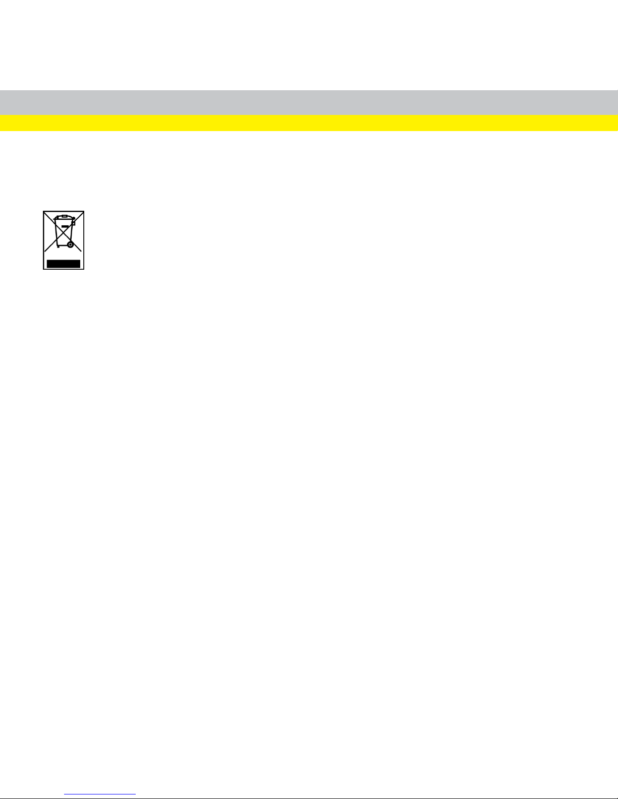
In order to avoid the dissemination of those substances in our environment and to
diminish the pressure on the natural resources, we encourage you to use the
appropriate take-back systems for product disposal. Those systems willreuse or
recycle most of the materials of the product you are disposing in a sound way.
The crossed out wheeled bin symbol informs you that the product should not
be disposed of along with municipal waste and invites you to use the appropriate
separate take-back systems for product disposal.
If you need more information on the collection, reuse, and recycling systems, please
contact your local or regional waste administration.
You may also contact your supplier for more information on the environmental
performance of this product.
15
Page 16
China RoHS
Hazardous Substances 有 害物 质
Part Name
部 件 名 称
Lead (Pb)铅Mercury
(Hg)
汞
Cadmium
(Cd)
镉
Hexavalent
Chromium
(Cr (VI))
六 价 铬
Polybrominated
biphenyls (PBB)
多 溴 联 苯
Polybrominated
diphenyl ethers
(PBDE)
多 溴 二 苯醚
DM50
X O O O O O
This table is prepared in accordance with the provisions of SJ/T 11364.
这 个 标 签是 根据 SJ / T 11364 的规 定准 备的 。
O: Indicates that said hazardous substance contained in all of the homogeneous materials for this part is below the
limit requirement of GB / T26572 - 2011.
表 示 本 部件 所有 均质 材料 中含 有的 有 害 物 质低 于GB / T26572 - 2011 的 限量 要求 。
X: Indicates that said hazardous substance contained in at least one of the homogeneous materials used for this
part is above the limit requirement of GB / T26572 - 2011.
表 示 用 于本 部件 的至 少一 种均 质材 料 中 所 含的 危害 物质 超过 GB / T26572 - 2011 的限 制要 求 。
16
Page 17

Copyright © 2017
Cognex Corporation. All Rights Reserved.
 Loading...