

Page 1

®
DataMan
Quick Reference Guide
150
4/24/2015
Version 5.5.0
Page 2

Legal Notices
Legal Notices
The software described in this document is furnished under license, and may be used or copied only in accordance with
the terms of such license and with the inclusion of the copyright notice shown on this page. Neither the software, this
document, nor any copies thereof may be provided to, or otherwise made available to, anyone other than the licensee.
Title to, and ownership of, this software remains with Cognex Corporation or its licensor. Cognex Corporation assumes
no responsibility for the use or reliability of its software on equipment that is not supplied by Cognex Corporation.
Cognex Corporation makes no warranties, either express or implied, regarding the described software, its
merchantability, non-infringement or its fitness for any particular purpose.
The information in this document is subject to change without notice and should not be construed as a commitment by
Cognex Corporation. Cognex Corporation is not responsible for any errors that may be present in either this document or
the associated software.
Companies, names, and data used in examples herein are fictitious unless otherwise noted. No part of this document
may be reproduced or transmitted in any form or by any means, electronic or mechanical, for any purpose, nor
transferred to any other media or language without the written permission of Cognex Corporation.
Copyright © 2015. Cognex Corporation. All Rights Reserved.
Portions of the hardware and software provided by Cognex may be covered Cognex Corporation. All Rights Reserved.
by one or more U.S. and foreign patents, as well as pending U.S. and foreign patents listed on the Cognex web site at:
http://www.cognex.com/patents.
The following are registered trademarks of Cognex Corporation:
Cognex, 2DMAX, Advantage, Alignplus, Assemblyplus, CheckitwithChecker, Checker, CognexVisionforIndustry,
CognexVSOC, CVL, DataMan, DisplayInspect, DVT, EasyBuilder, Hotbars, IDMax, In-Sight, LaserKiller, MVS-8000,
OmniView, PatFind, PatFlex, PatInspect, PatMax, PatQuick, SensorView, SmartView, SmartAdvisor, SmartLearn,
UltraLight, VisionSolutions, VisionPro, VisionView
The following are trademarks of Cognex Corporation:
The Cognex logo, 1DMax, 3D-Locate, 3DMax, BGAII, CheckPoint, CognexVSoC, CVC-1000, FFD, iLearn, In-Sight
(design insignia with cross-hairs), In-Sight2000, InspectEdge, Inspection Designer, MVS, NotchMax, OCRMax,
ProofRead, SmartSync, ProfilePlus, SmartDisplay, SmartSystem, SMD4, VisiFlex, Xpand, PowerGrid, Hotbars2
Other product and company trademarks identified herein are the trademarks of their respective owners.
2
Page 3

Table of Contents
Table of Contents
Legal Notices 2
Table of Contents 3
Symbols 4
Getting Started 5
About DataMan 150 5
DataMan 150 Accessories 6
DataMan 150 Systems 7
Communication Modules 9
DataMan 150 Cable Pinouts 9
Reader Layout 10
Dimensions 13
Installing an Optical Filter 15
Installing a Liquid Lens 17
Changing from a 6.2 mm Lens to a 16 mm Lens 19
Changing to anIllumination with a Different Color 22
Setting Up Your DataMan 24
Mounting 24
I/O Cable 25
RS-232Cable 25
Flying Leads Cable 26
USB Connections 27
RS-232Connections 28
Wiring the Basic I/O Module 29
Digital Input Wiring Diagrams 30
Digital Output Wiring Diagrams 32
Installing the DataMan Software 34
Setting the Focus Position 35
Field of View and ReadingDistances 37
External Triggering and TriggerModes 38
Trainingand Trigger Modes 38
Training 38
Incremental Training for Multiple Symbologies 39
Tuning 40
Multi-port Connections 40
DataMan 150 Specifications 43
Imager Specifications 43
Precautions 44
Regulations/Conformity 45
3
Page 4
Symbols
The following symbols indicate safety precautions and supplemental information.
WARNING: This symbol indicates the presence of a hazard that could result in death, serious personal injury or
electrical shock.
CAUTION: This symbol indicates the presence of a hazard that could result in property damage.
Note: Notes provide supplemental information about a subject.
Tip: Tips provide helpful suggestions and shortcuts that may not otherwise be apparent.
Symbols
4
Page 5
Getting Started
Getting Started
About DataMan 150
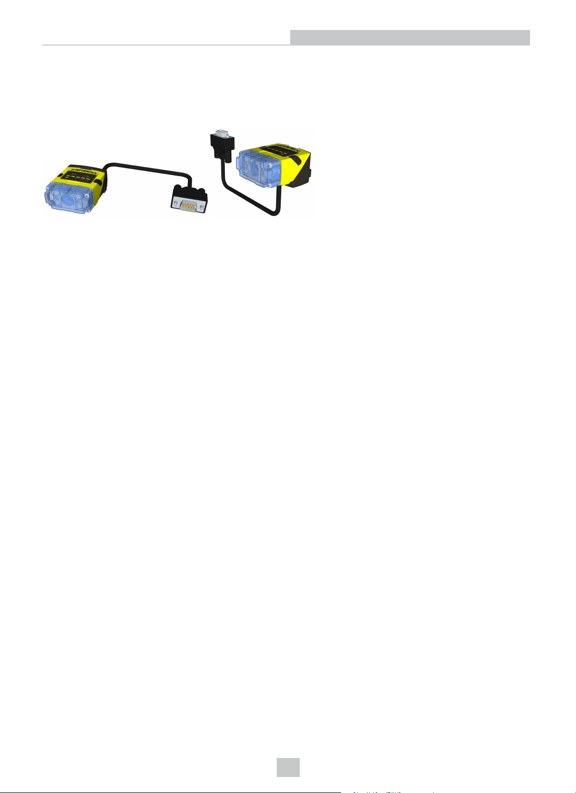
The DataMan 150 readers are best in class ID readers, offering superior performance with the latest ID tools, flexibility to
configure the reader in terms of lighting and optics to optimize the application, and an ease-of-use giving the user the
ability to setup and deploy an application quickly and efficiently all without the need for PC:
l Superior performance, 1-D and 2-D code reading, including HotBars2™ and patent-pending PowerGrid™
l Flexible optics/lighting, including field upgrades, allowing for the protection of your investment
l Ease-of-use, including an auto-tune and trigger button on the reader, the ability to configure the reader in a
straight or right-angle orientation and auto-focus capability utilizing a liquid lens
The DataMan 150 readers provide support for USB and RS-232 communications.
Key highlights:
l 1DMax with HotBars2™, best in class 1-D reading, 2DMax with PowerGrid™, best in class 2-D reading. Reading
codes no other ID reader on the market can.
l Multiple options for LED lighting, along with optical filters and polarizing filters. Options for different powered lens,
with autofocus capabilities for each.
l Intelligent tuning and dynamic configuration of the reader combined to make the installation and setup of the
application a snap.
This document provides basic information about how to configure and use DataMan 150 readers. Additional information
is available through the Windows Start menu or the DataMan Setup Tool Help menu after you install the DataMan
software on your PC:
l The DataMan Communications & Programming Guide shows how to integrate your DataMan reader with your
automation software and factory network.
Cognex->DataMan Software v x.x.x->Documentation->CommunicationsAnd Programming
l The DataMan Reader Configuration Codes document provides printable 2-D codes that you can use to
configure the DataMan reader.
Cognex->DataMan Software v x.x.x->Documentation->English->Reader Configuration Codes
l The DataMan Fixed Mount Readers Reference is a complete online hardware reference for the DataMan fixed-
mount ID readers.
Cognex->DataMan Software v x.x.x->Documentation->English->DM150 ->Fixed Mount Reference Manual
l The DataMan Questions and Answers document provides context-sensitive information. You can view this help
inside the DataMan Setup Tool or as a stand-alone help file.
Cognex->DataMan Software v x.x.x->Documentation->DM150->Questionsand Answers
l The Release Notes list detailed system requirements and additional information about this DataMan software
release.
Cognex->DataMan Software v x.x.x->Documentation->DataMan vx.x.xRelease Notes
5
Page 6
DataMan 150 Accessories
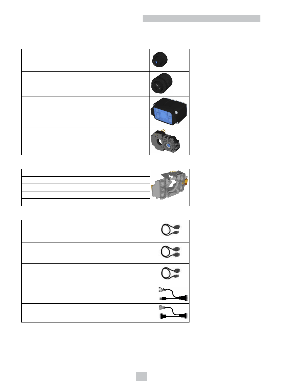
LENS OPTIONS
6.2 mm lens (DM150-LENS-62 )
16 mm lens with extended optics mount (requires the use of
extended front cover) (DM260-LENS-16)
Extended lens cover, used with 16mm lens (DM260-LENS16CVR)
Extended lens cover, used with 16mm lens, polarized (DM260LENS-16CVR-P)
Liquid Lens used with 6.2 mm lens (DM150-LENS-62LL)
16mm lens with Liquid Lens kit including LED Polarized Cover
(DM260-LENS-16LL)
Getting Started
LIGHTOPTIONS
Red LED illumination (DM150-LED-RED)
White LED illumination (DM150-LED-WHT)
Blue LED illumination (DM150-LED-BLU)
IRLED illumination (DM150-LED-IR)
High Powered red LED illumination (DM260-LED-RED-HP)
CABLES
5-meter extension cable* (DM100-EXTCBL-000)
RS-232/USB adapter for Expansion I/O Module (DM100-PATCH-
000)
USB adapter cable with power tap (DM100-USB-000)
USB adapter cable with power tap (DM100-USB-030)
USB & Flying Leads I/O Cable, 2.0 m (DM-USBIO-00)
RS-232 & Flying Leads I/O Cable, 2.5 m (DM-RS232IO-00)
6
Page 7
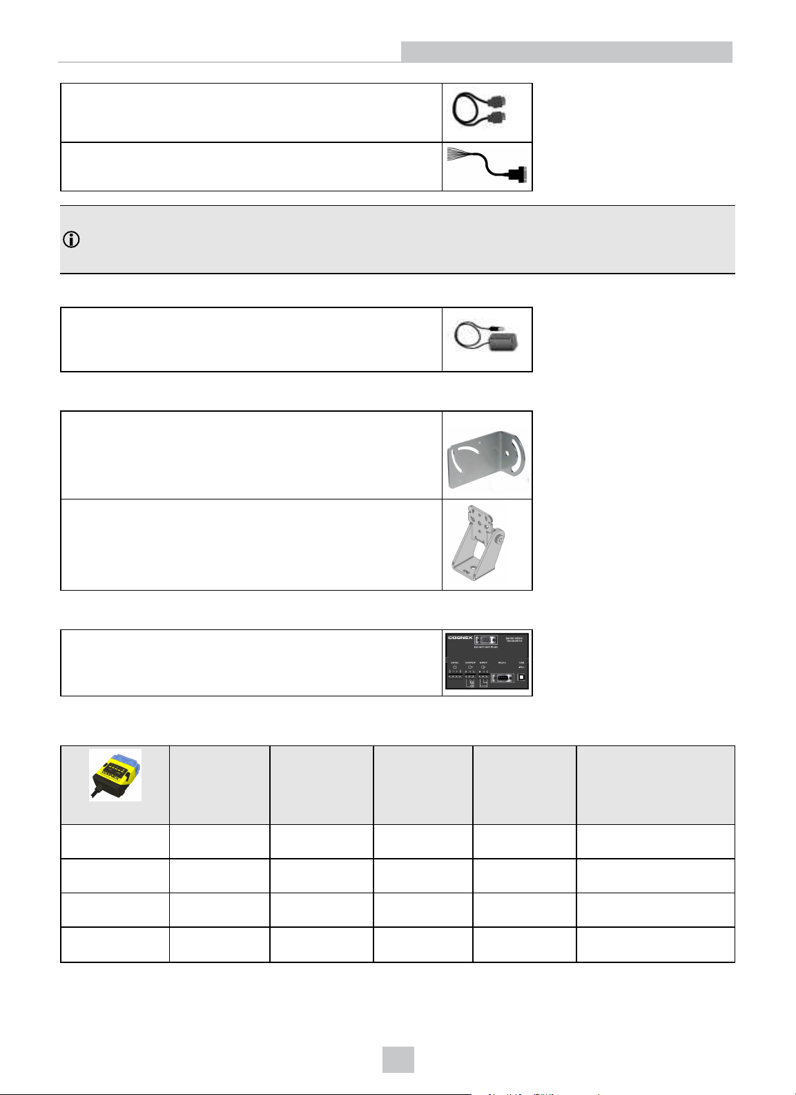
RS-232 adapter cable with power tap (DM100-RS232-000)
Flying Leads Connection Cable, 5 m (DM50-PWRIO-05)
Note: *USB/RS-232 extension connection is possible with the following limitations:
1. The USB connection is shorter than 5m.
2. Serial connection is shorter than 15m.
POWERSUPPLIES
Power supply, 6V (DM100-PWR-000)
MOUNTINGBRACKETS
Mounting bracket (DM100-UBRK-000)
Getting Started
Pivot mounting bracket (DM100-PIVOTM-00)
IOMODULES
DataMan Basic I/O Module (DM100-IOBOX-000)
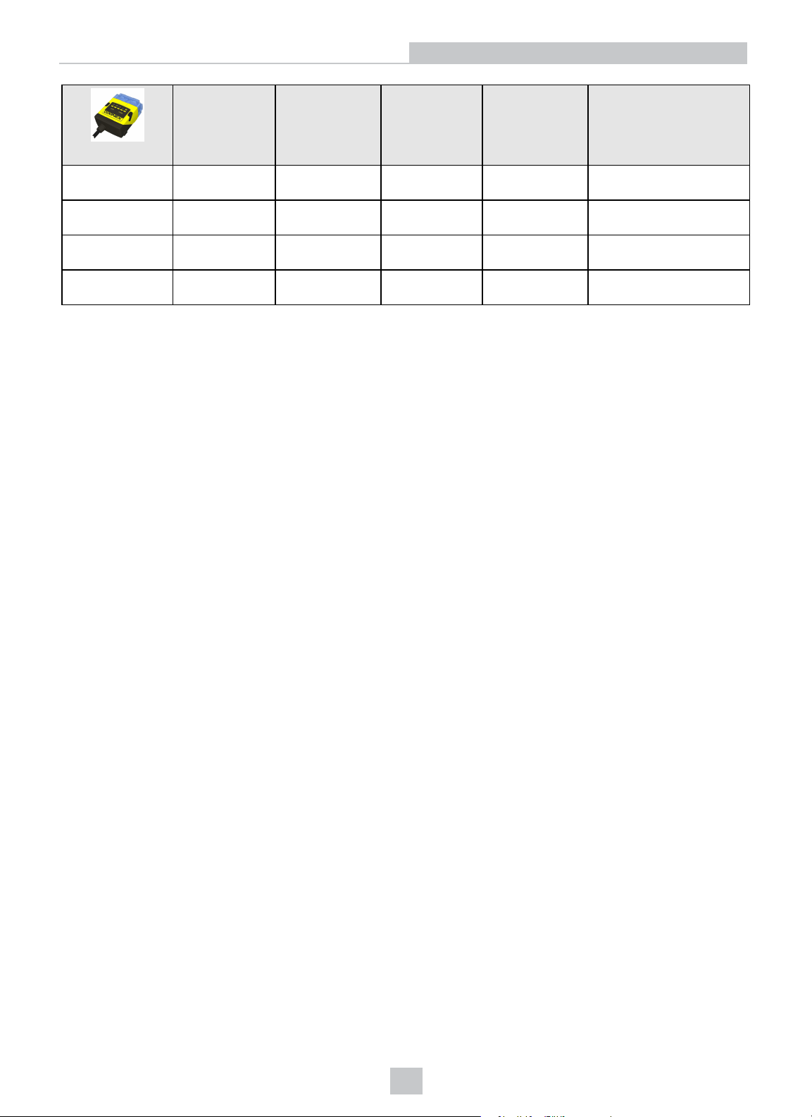
DataMan 150 Systems
DataMan 150S*
(DMR-150S-00)
DataMan 150QL
(DMR-150QL-00)
DataMan 150Q
(DMR-150Q-00)
DataMan 150X
(DMR-150X-00)
Omni-
directional 1-D
Code Reading
√ √ √ 752x480 Global shutter
√ √ 752x480 Global shutter
√ √ 752x480 Global shutter
√ √ √ 752x480 Global shutter
1DMax+™ —
Best-In-Class 1-
D Reading
IDQuick™ —
High-Speed 2-D
Reading
2DMax+™ — for
hard to read
DPM and
damaged 2-D
codes
Resolution
7
Page 8
Getting Started
Omni-
directional 1-D
Code Reading
DataMan 152S*
(DMR-152S-00)
DataMan 152QL
(DMR-152QL-00)
DataMan 152Q
(DMR-152Q-00)
DataMan 152X
(DMR-152X-00)
*Maximum decode rate of 2 codes/sec
√ √ √ 1280x960 Global shutter
√ √ 1280x960 Global shutter
√ √ 1280x960 Global shutter
√ √ √ 1280x960 Global shutter
1DMax+™ —
Best-In-Class 1-
D Reading
IDQuick™ —
High-Speed 2-D
Reading
2DMax+™ — for
hard to read
DPM and
damaged 2-D
codes
Resolution
8
Page 9
Communication Modules
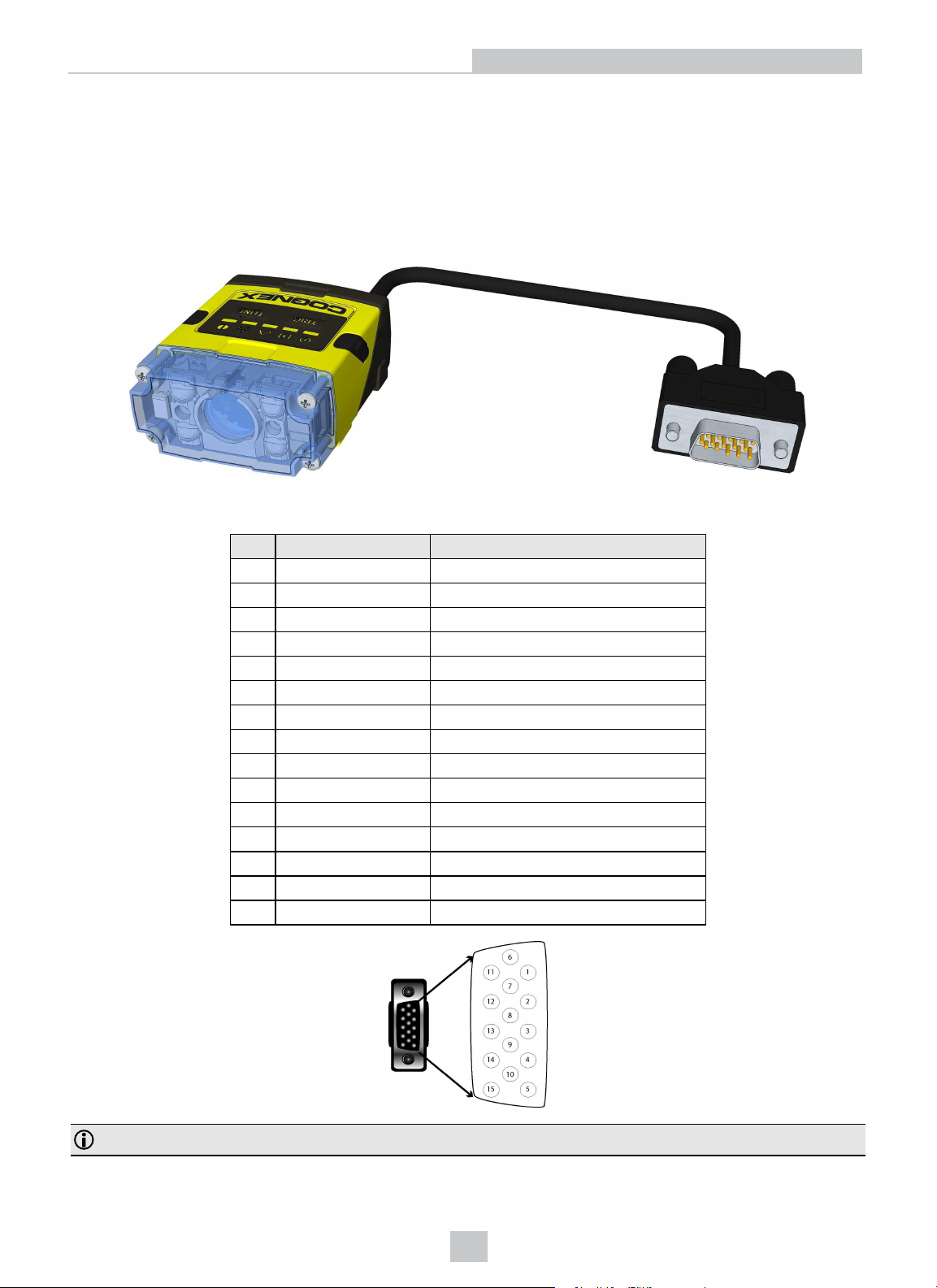
The DataMan 150 is available with the following communication options:
l USB/RS-232
DataMan 150 Cable Pinouts
The I/O module with USB has all signals on a SUB-D 15 connector with the following pinouts:
Getting Started
PIN Color Signal
1 Brown Reserved
2 Green TxD (RS-232)
3 Green/Black RxD (RS-232)
4 Red & Red/Black GND
5 Brown/White DC+ (system power, 5-24 VDC)
6 Blue RTS
7 Blue/White Output-0
8 White Input-0
9 White/Black Input-1
10 Light Blue CTS
11 Light Blue/Black Output-1
12 Light Blue/Yellow Output-Common
13 Light Blue/Green Input-Common
14 Yellow Reserved
15 Yellow/Black Reserved
Note: Pin numbers are shown for cable connector, not I/O module.
9
Page 10
Reader Layout
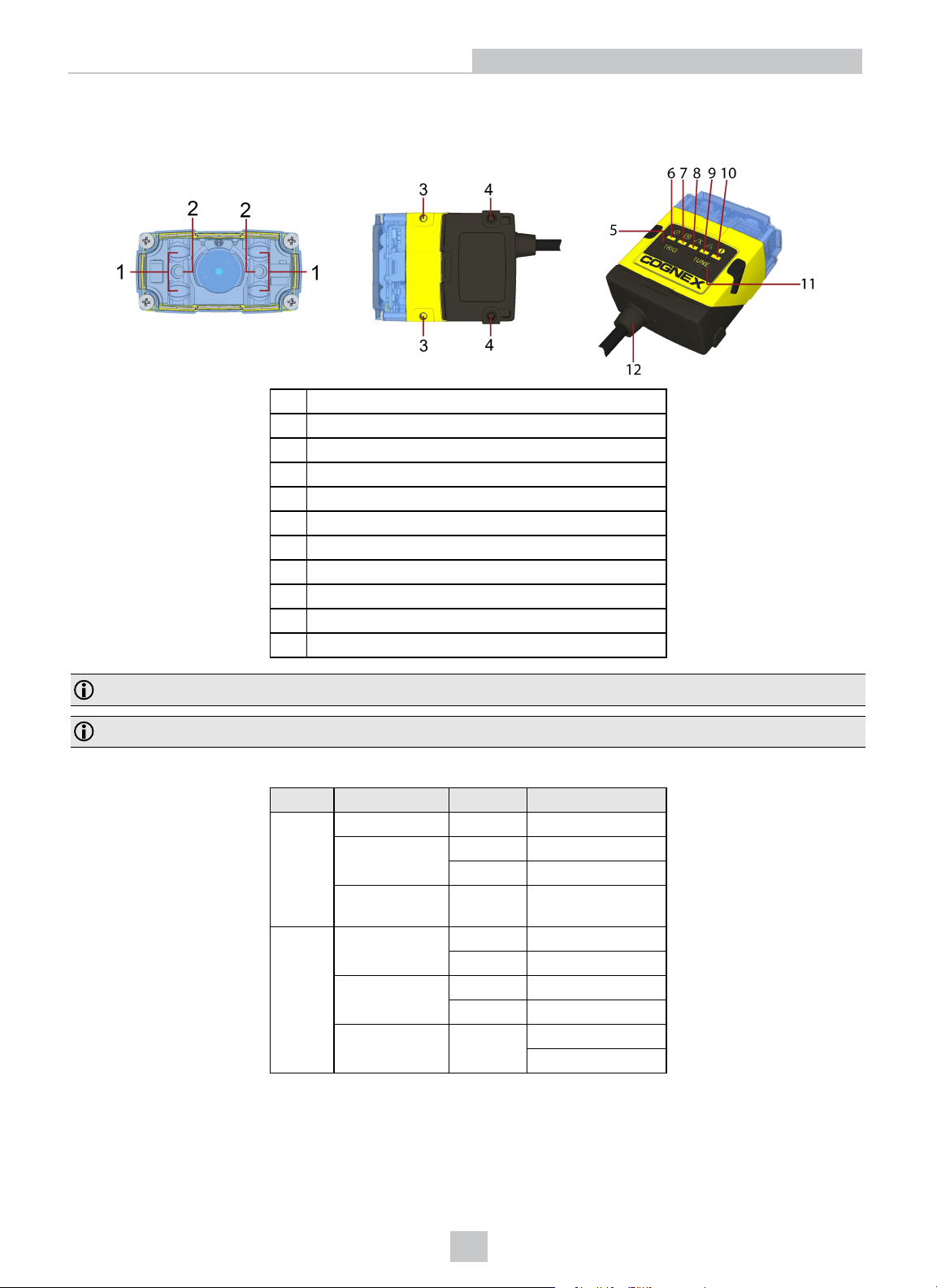
The following images show the built-in lighting system and other features of the DataMan 150 reader.
1 Illumination LEDs
2 LED aimers
3-4* Mounting holes (M3 x 3.5mm)
5 Trigger button
6 Power
7 Train status/Trigger status
8 Good/bad read
9 Communication
10 Error
11 Tune button
12 Power, I/O and RS-232
Getting Started
Note: *Use only one set of mounting holes (either 3 OR 4) for mounting.
Note: The five status LEDs together also function as a peak meter using an orange light.
Indicator LEDs
Type Signal Color Meaning
Status Power GREEN Power ON
Train status GREEN Trained
YELLOW Untrained
Error RED Error - check
device log
Action Good/bad read GREEN Good read
RED Bad read
Communication YELLOW Link up
blink
Peak meter Yellow Tune
Data transfer
Focus
10
Page 11
Getting Started
Changing Orientation
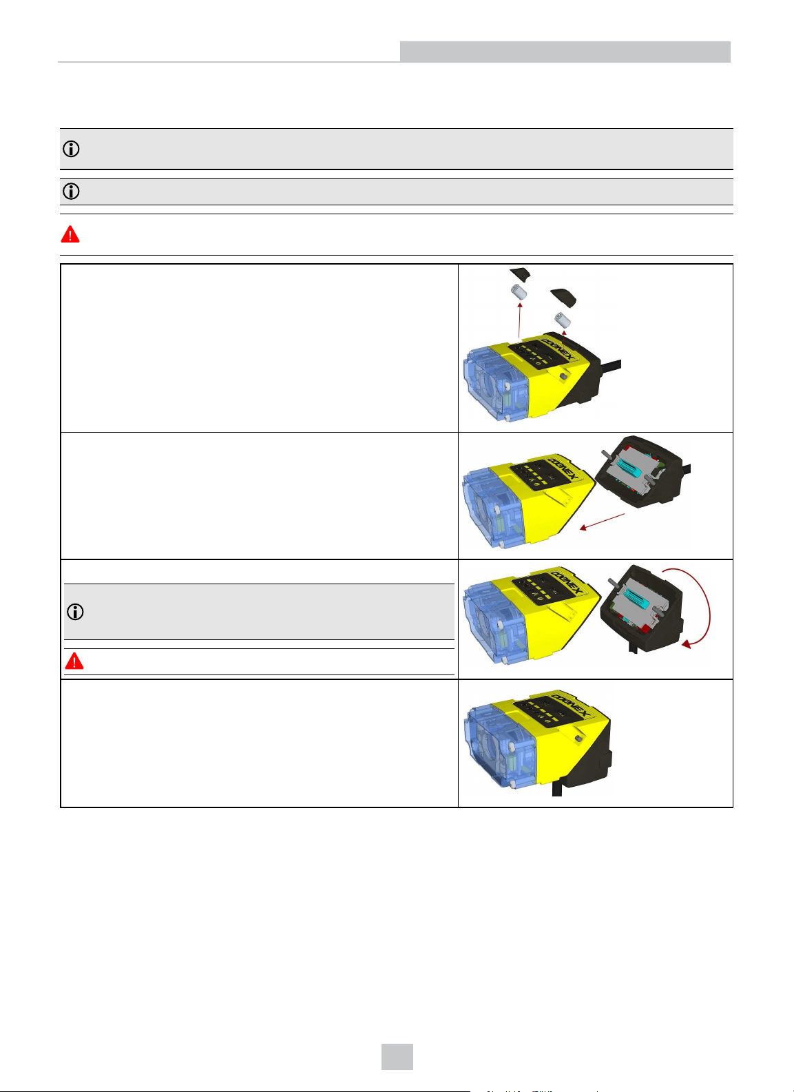
Perform the following steps to change between straight and angled configuration.
Note: Switching between straight and right angle configuration is recommended only up to 10 times in the lifetime
of the reader.
Note: Disconnect the DataMan 150 reader from power before changing the orientation.
WARNING: Make sure that no electrostatic charges are applied to the PCB. (E.g. wear ESD shoes.) If the main
module is separated from the I/O module, take care to assemble them correctly. Otherwise, IP rating can be lost.
1. Remove the screw covers and unscrew the screws.
2. Disconnect the main module and the I/O module by firmly pulling
them apart.
3. Change the orientation.
Note: Make sure that the gasket it properly seated on main
module. Ensure that the flat gasket side is facing away from the
module.
WARNING: Do not touch any electrical component.
5. Connect the I/O module to the main module.
11
Page 12
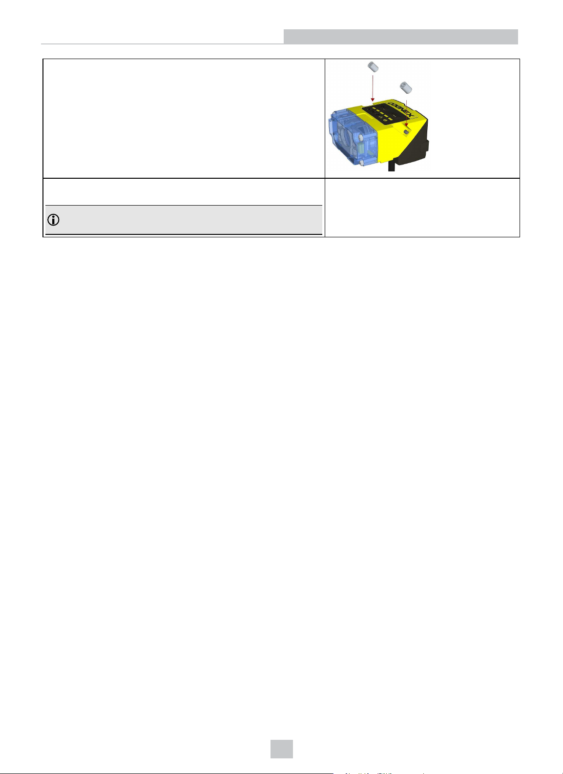
6. Loosely fasten the modules together with the two T10 cap nut
screws until they attach to the housing surface, but do not torque.
7. After each cap nut has been fastened, torque them to 0.12 Nm and
place back the screw covers.
Note: There are unique left and right screw covers. Take care to
attach them correctly.
Getting Started
12
Page 13
Getting Started
Dimensions
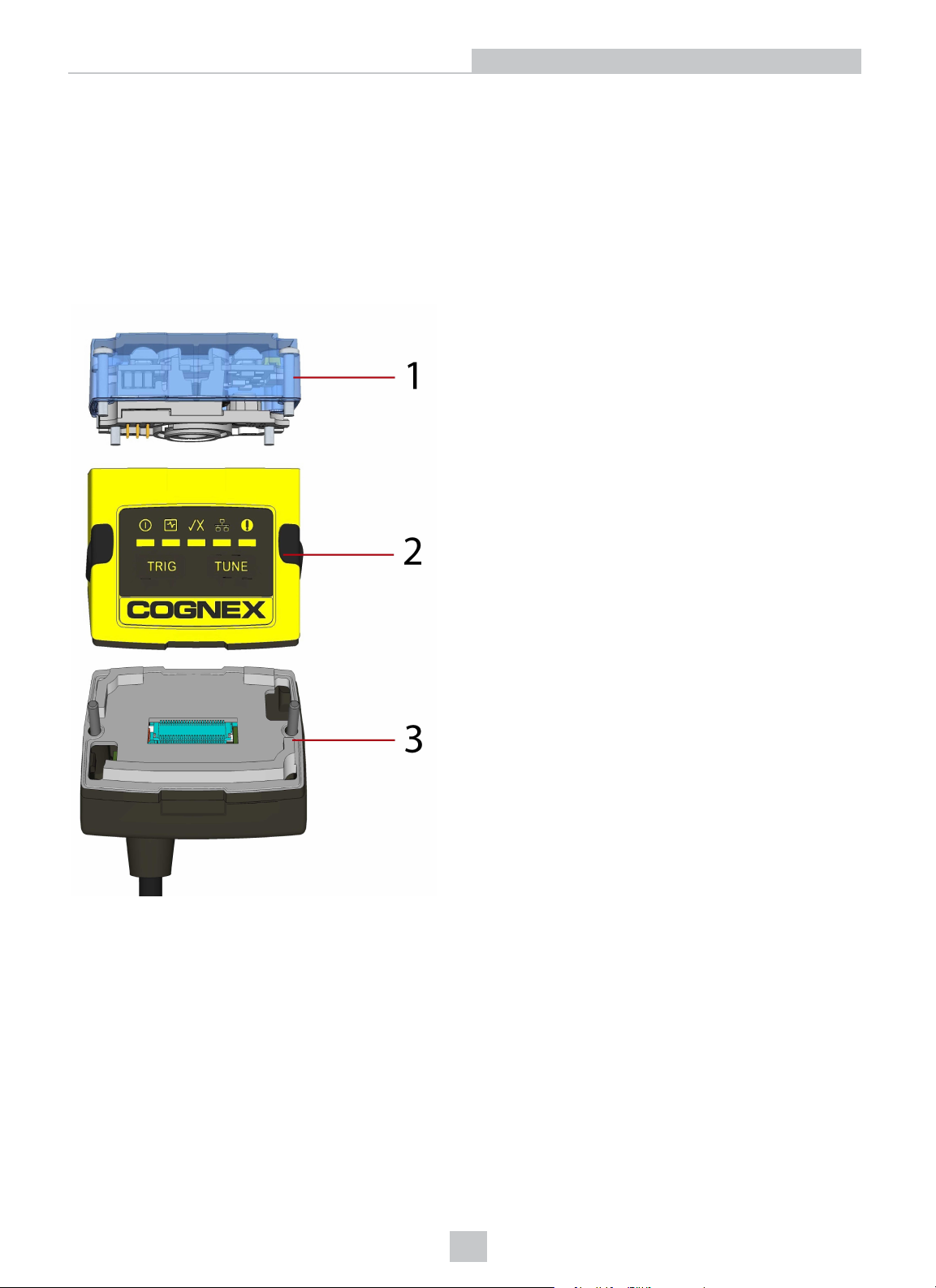
The DataMan 150 consists of three main parts:
1. Optics module (lens including lens mount, illumination and front cover including filter mounting option for a
Diameter (Ø): 12.3mm<Ø<12.7mm, Thickness (t): 1.6mm<t<2mm filter)
2. Main module, including sensor and CPU
3. I/O module
13
Page 14
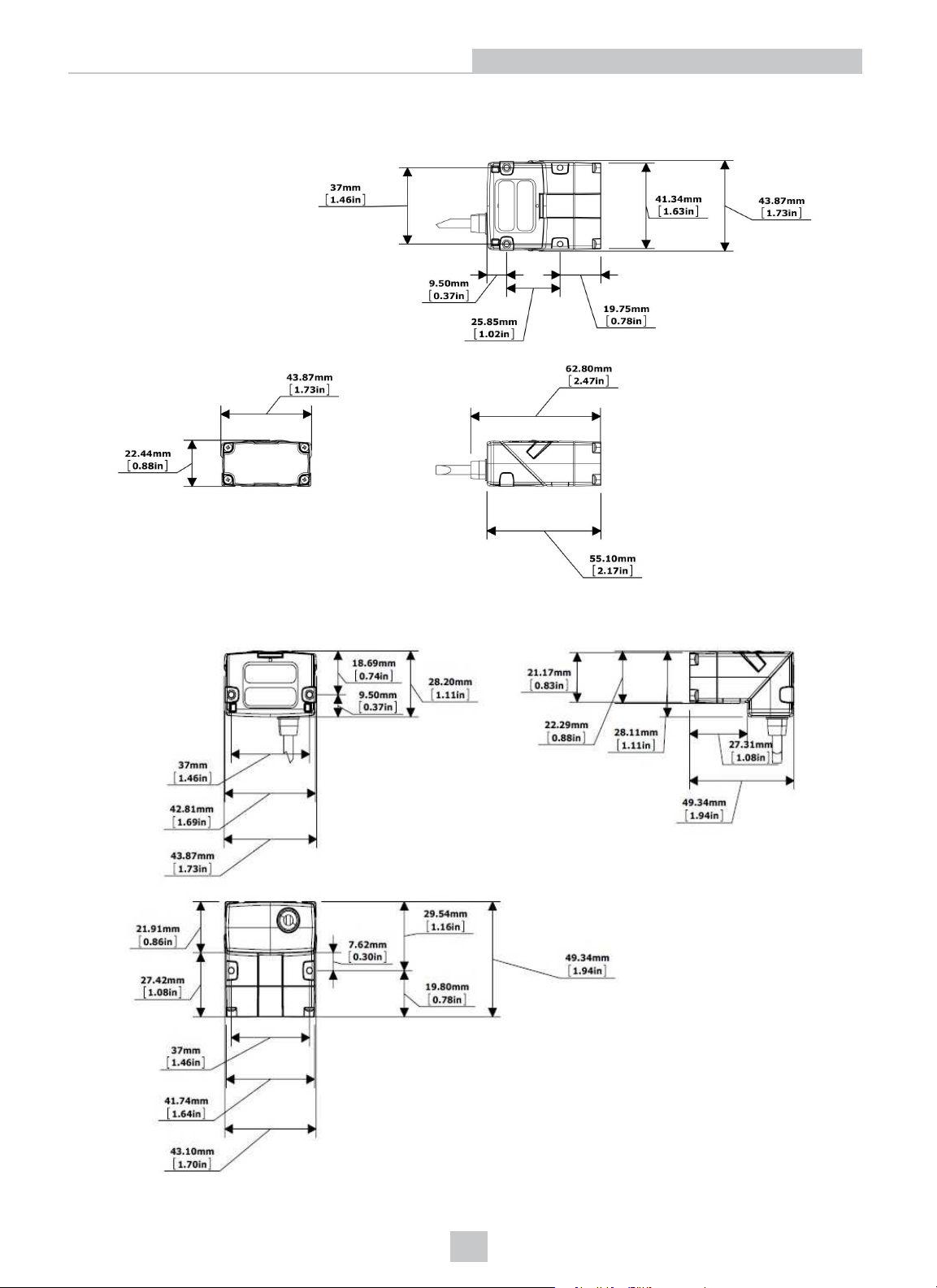
The size of the DataMan 150 in the straight configuration is shown in the following figure:
Getting Started
The size of the DataMan 150 in the angled configuration is shown in the following figure:
14
Page 15
Installing an Optical Filter
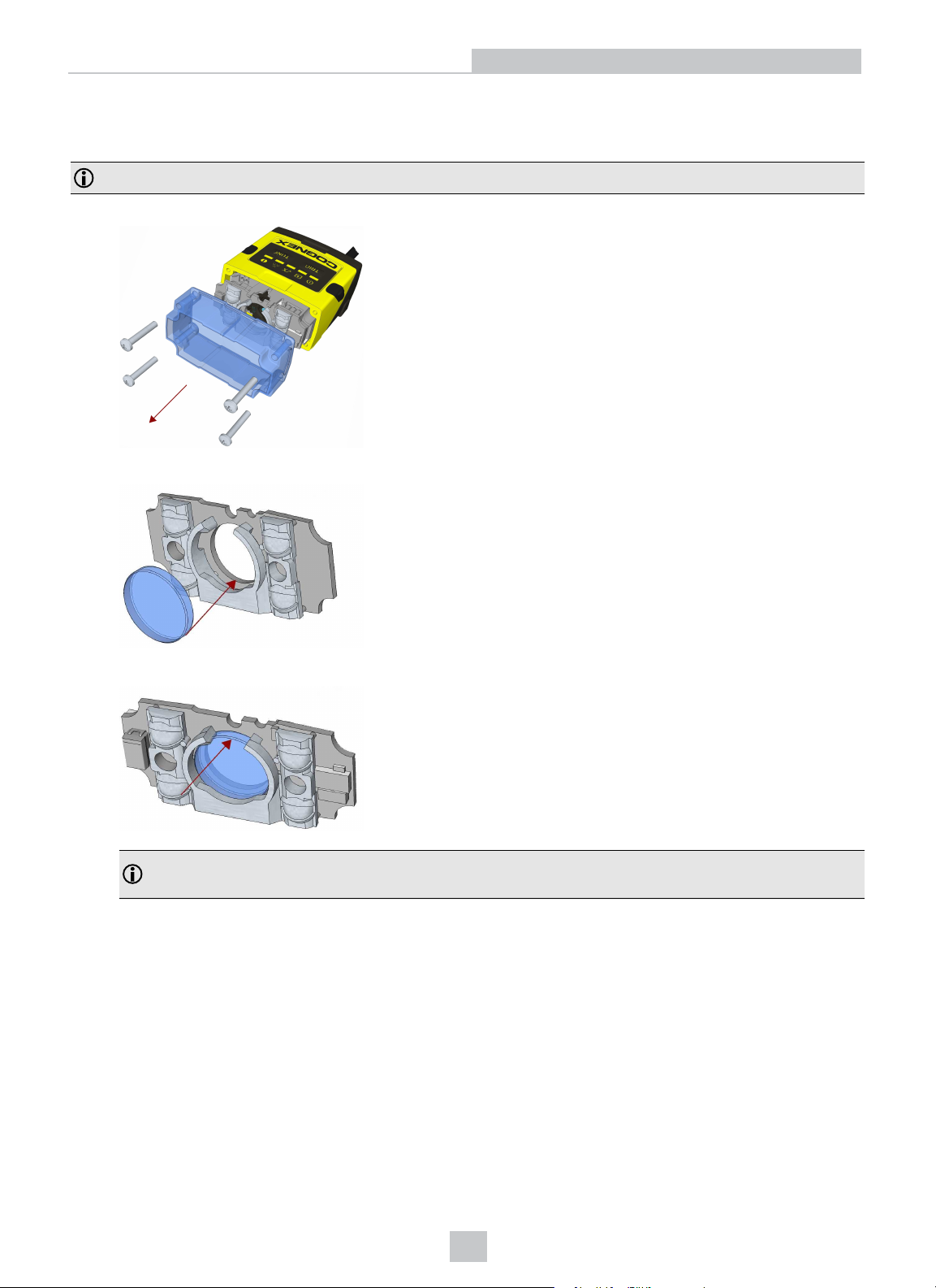
Perform the following steps to install an optical filter in the optics module of the DataMan 150 reader.
Note: Disconnect the DataMan 150 reader from power before installing an optical filter.
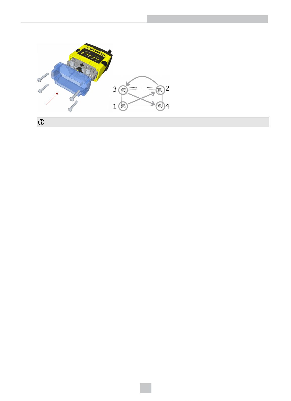
1. First, remove the front cover: unscrew the four screws and take off the LEDcover.
2. Insert the filter at the bottom side of the round opening in the transparent plastic part.
Getting Started
3. Push the top side of the filter firmly until it is sitting flat against the PCB.
Note: Use finger to push the filter in and then a q-tip to clean the filter, or use a q-tip to push the filter into
place.
15
Page 16
Getting Started
4. Attach the front cover. Observing the tightening sequence below, tighten all four screws to 9 Ncm using a torque
wrench.
5.
Note: The rib in the front cover must be oriented to the top side.
16
Page 17
Installing a Liquid Lens
Perform the following steps to install a liquid lens on your DataMan 150 reader.
Note: Disconnect the DataMan 150 reader from power before installing the liquid lens.
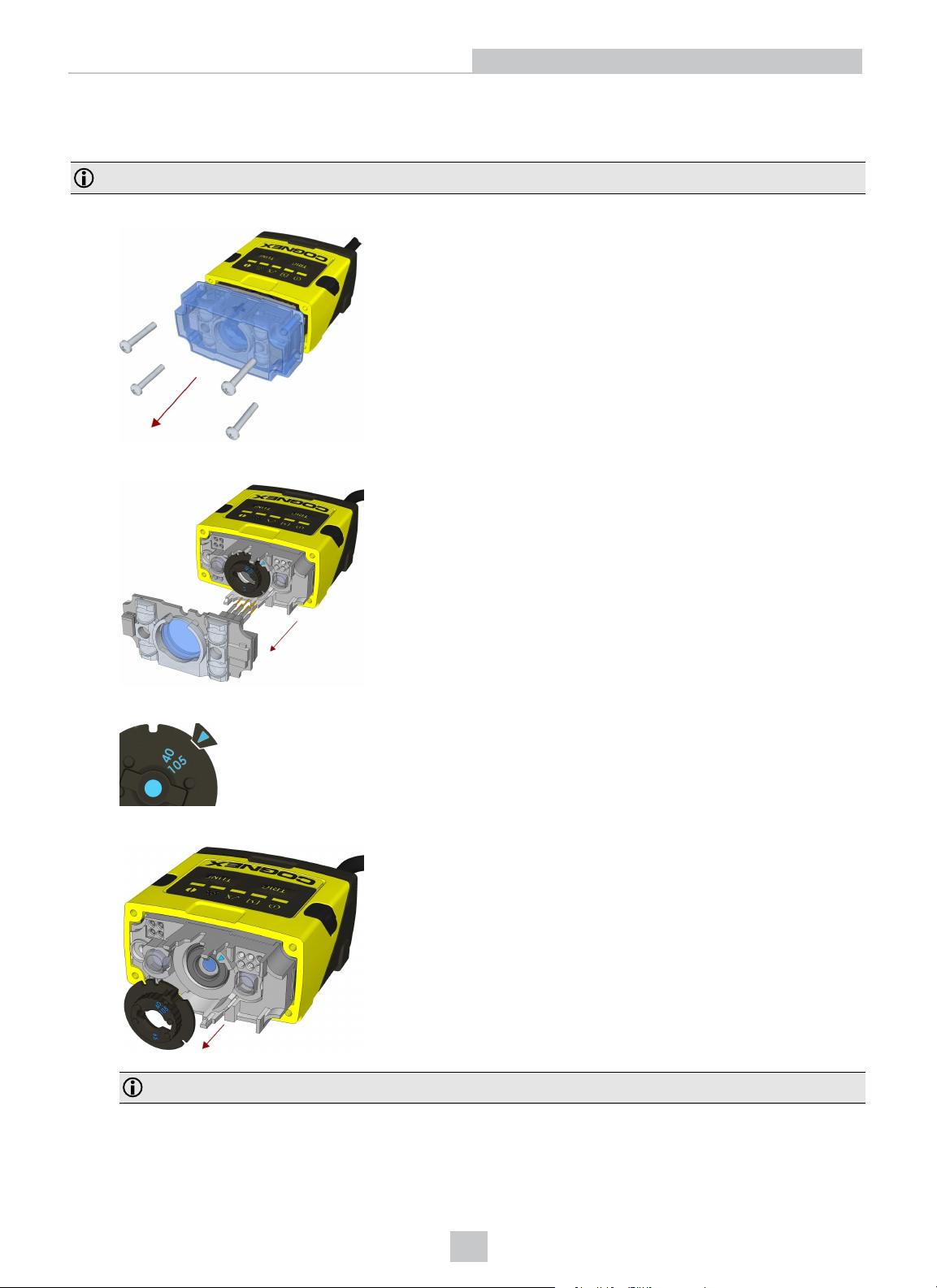
1. Remove the front cover: unscrew the four screws and take off the LEDcover.
2. Remove the illumination module.
Getting Started
3. Turn the lens cap to the 105 mm position.
4. Remove the lens cap from the imager lens by pulling it.
Note: Do not rotate the imager lens while the lens cap is removed. Otherwise, focus calibration will be lost.
17
Page 18
Getting Started
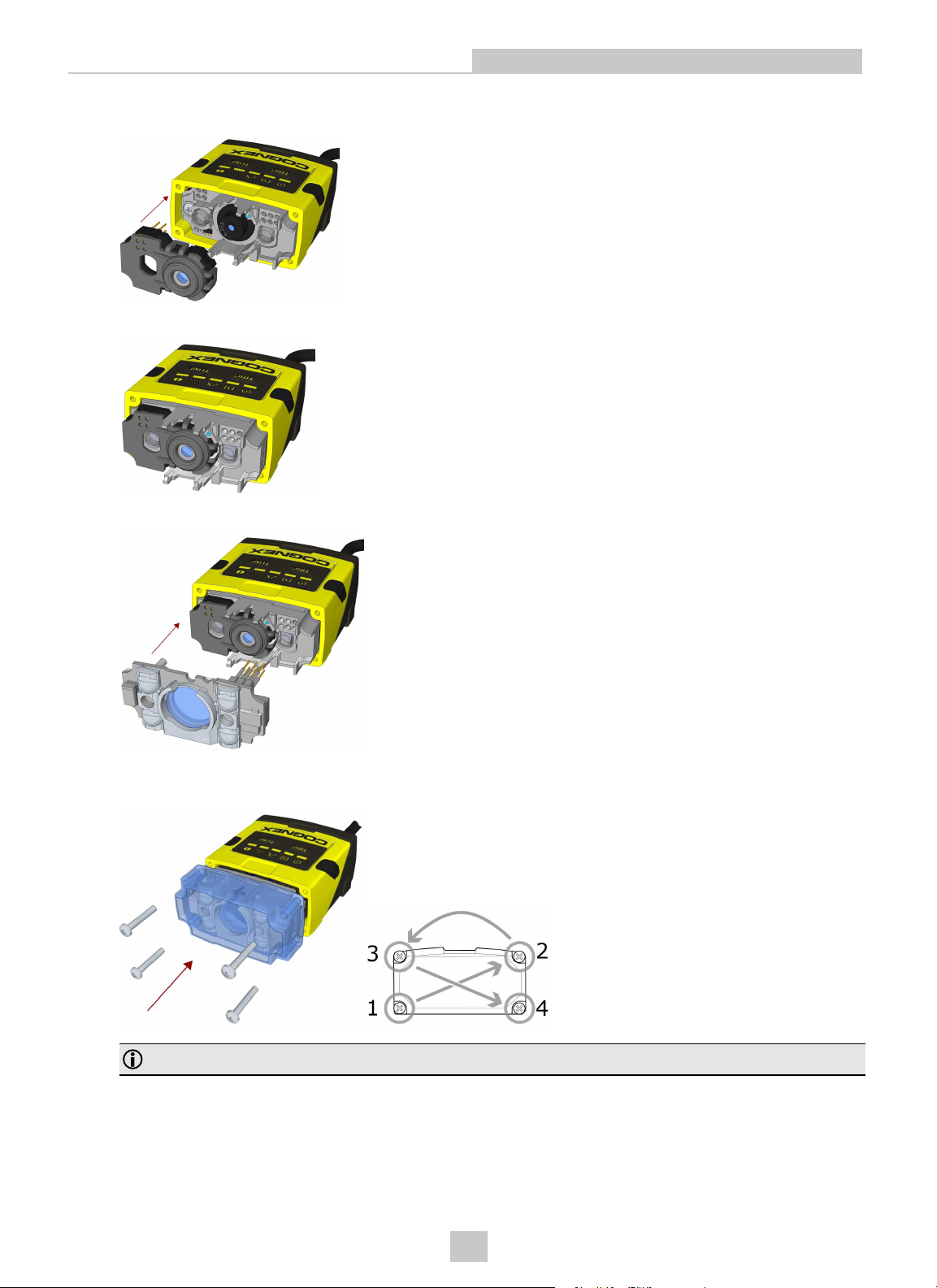
5. Attach the liquid lens accessory by aligning the 2x2 connectors of the liquid lens with the 2x2 sockets on the
optics mount.
6. Press the liquid lens onto the imager lens until you reach the stop.
7. Reattach the illumination.
8. Attach the front cover. Observing the tightening sequence below, tighten all four screws to 9 Ncm using a torque
wrench.
Note: The rib in the front cover must be oriented to the top side.
18
Page 19
Changing from a 6.2 mm Lens to a 16 mm Lens
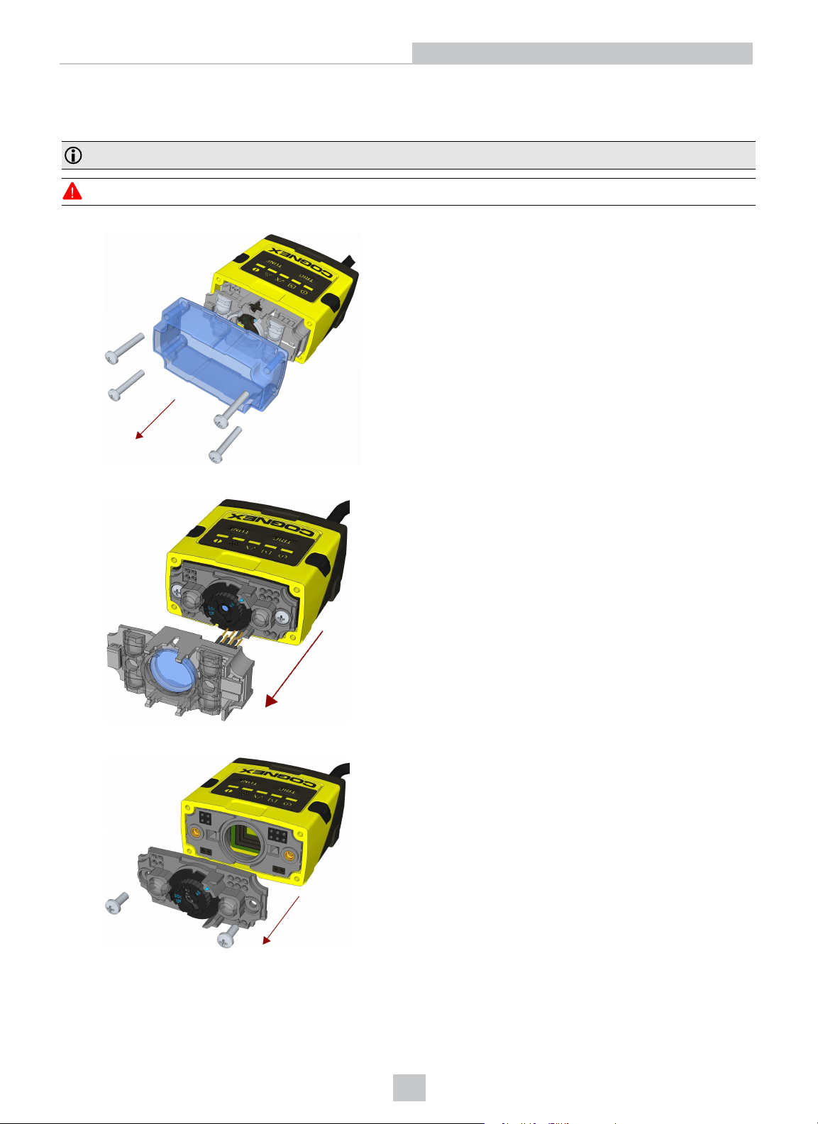
Perform the following steps to change a 6.2 mm lens to a 16 mm lens on your DataMan 150 reader.
Note: Disconnect the DataMan 150 reader from power before changing lenses.
WARNING: This modification must be made in a dust-free and ESD safe area.
1. Remove the front cover: unscrew the four screws and take off the LEDcover.
Getting Started
2. Remove the illumination module.
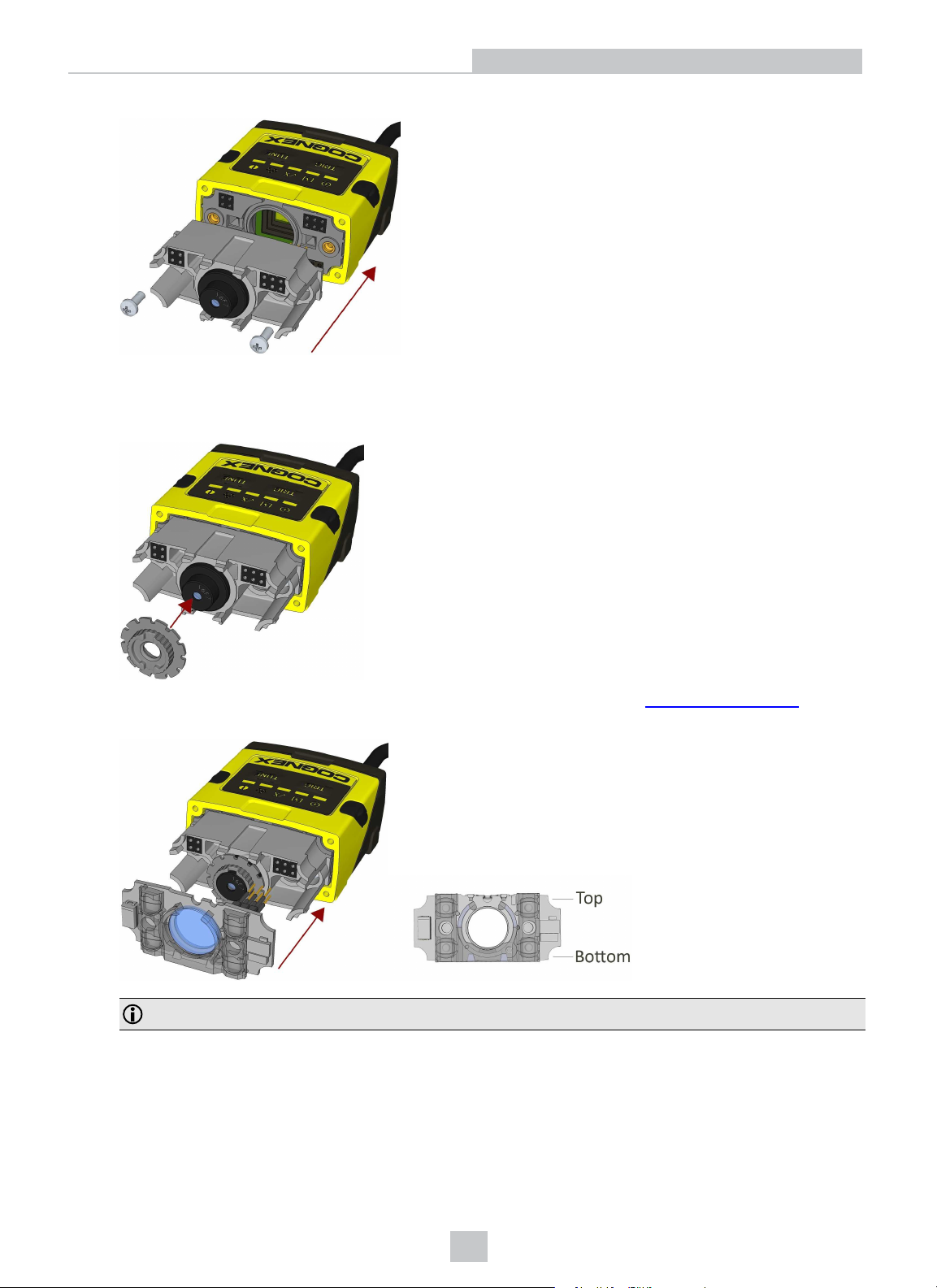
3. Unscrew the two Phillips head screws and remove the 6.2 mm lens mount.
19
Page 20
Getting Started
4. Attach the 16 mm lens mount.
5. Fasten the two Phillips head screws to 0.06 Nm using a torque wrench.
6. In the case of a manual focus lens, press the 16 mm lens cap onto the lens. The lens has 12 cutouts so it can be
locked in steps of 30 degrees.
In the case of a liquid lens, mount the liquid lens cap onto the 16 mm lens. (See Installing a Liquid Lens.)
7. Attach the illumination board.
Note: Take care to attach the illumination with the right orientation.
20
Page 21
Getting Started
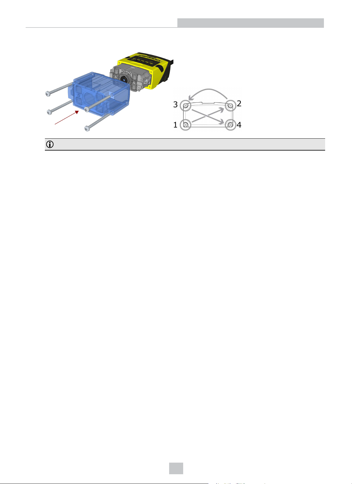
8. Attach the extended front cover. Observing the tightening sequence below, tighten all four screws to 9 Ncm using
a torque wrench.
Note: The rib in the front cover must be oriented to the top side.
21
Page 22
Getting Started
Changing to an Illumination with a Different Color
Perform the following steps to change the illumination.
Note: Disconnect the DataMan 150 reader from power before changing to an illumination with a different color.
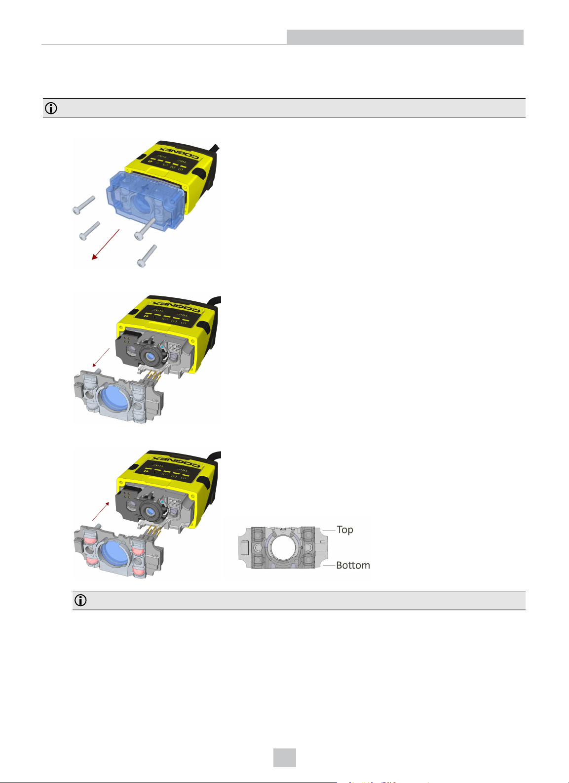
1. Remove the front cover: unscrew the four screws and take off the LEDcover.
2. Remove the illumination module.
3. Attach a new color illumination module.
Note: Take care to attach the illumination with the right orientation.
22
Page 23
Getting Started
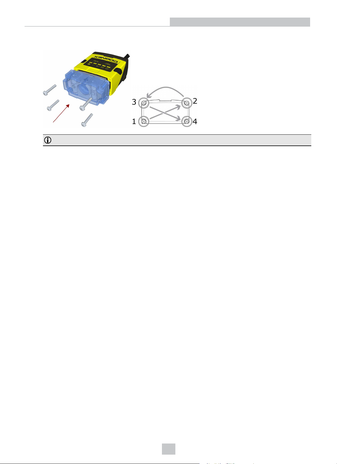
4. Attach the front cover. Observing the tightening sequence below, tighten all four screws to 9 Ncm using a torque
wrench.
Note: The rib in the front cover must be oriented to the top side.
23
Page 24
Setting Up Your DataMan
Setting Up Your DataMan
Mounting
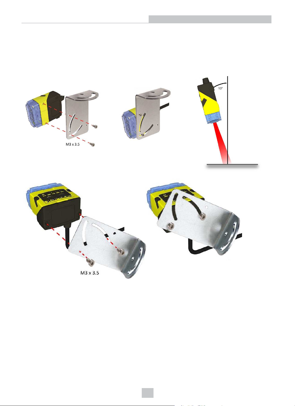
Mounting the DataMan 150 at a slight angle (15°) can reduce reflections and improve reader performance.
24
Page 25
Setting Up Your DataMan
I/O Cable
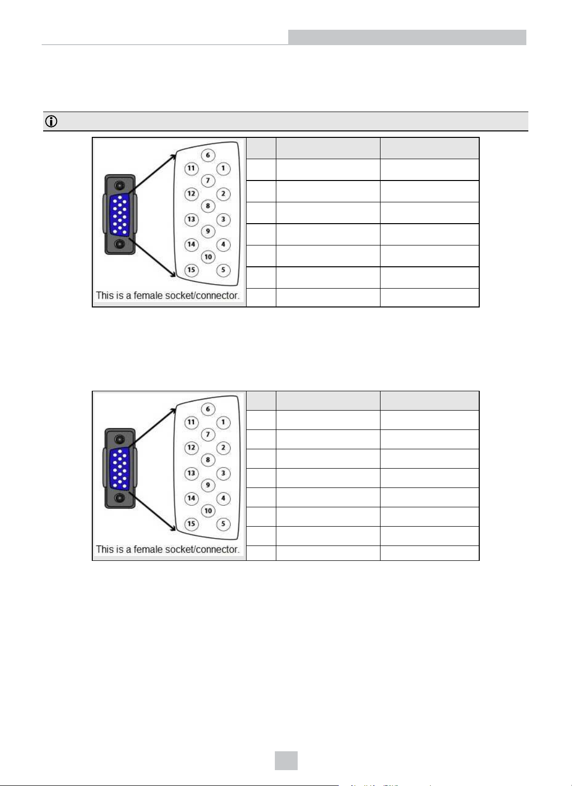
You can connect a cable with USB & flying leads (DM-USBIO-00) to the cable that is attached to the device. The
following table shows the pinout and color description of the flying leads.
Note: GND (Pin 4) is connected to the reader housing, cable shield, and DB15 shell.
PIN Color Signal
4 Black GND
7 Blue/White Output-0
8 White Input-0
9 White/Black Input-1
11 Light Blue/Black Output-1
12 Light Blue/Yellow Output-Common
13 Light Blue/Green Output-Strobe
RS-232 Cable
You can connect a cable with RS-232 & flying leads (DM-RS232IO-00) to the cable that is attached to the device. The
following table shows the pinout and color description of the flying leads.
PIN Color Signal
4 Black GND
5 Brown/White VDC
7 Blue/White Output-0
8 White Input-0
9 White/Black Input-1
11 Light Blue/Black Output-1
12 Light Blue/Yellow Output-Common
13 Light Blue/Green Output-Strobe
25
Page 26
Setting Up Your DataMan
Flying Leads Cable
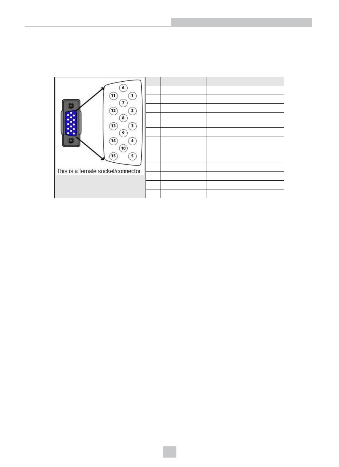
You can connect a cable with flying leads (DM50-PWRIO-05) to the cable that is attached to the device. The following
table shows the pinout and color description of the flying leads.
PIN Color Signal
2 Green TxD
3 Green/Black RxD
4 Red GND
5 Brown/White DC+(system power, 5-24
VDC)
6 Blue RTS
7 Blue/White Output-0
8 White Input-0
9 White/Black Input-1
10 Light Blue CTS
11 Light Blue/Black Output-1
12 Light Blue/Yellow Output-Common
13 Light Blue/Green Output-Strobe
26
Page 27
Setting Up Your DataMan
USB Connections
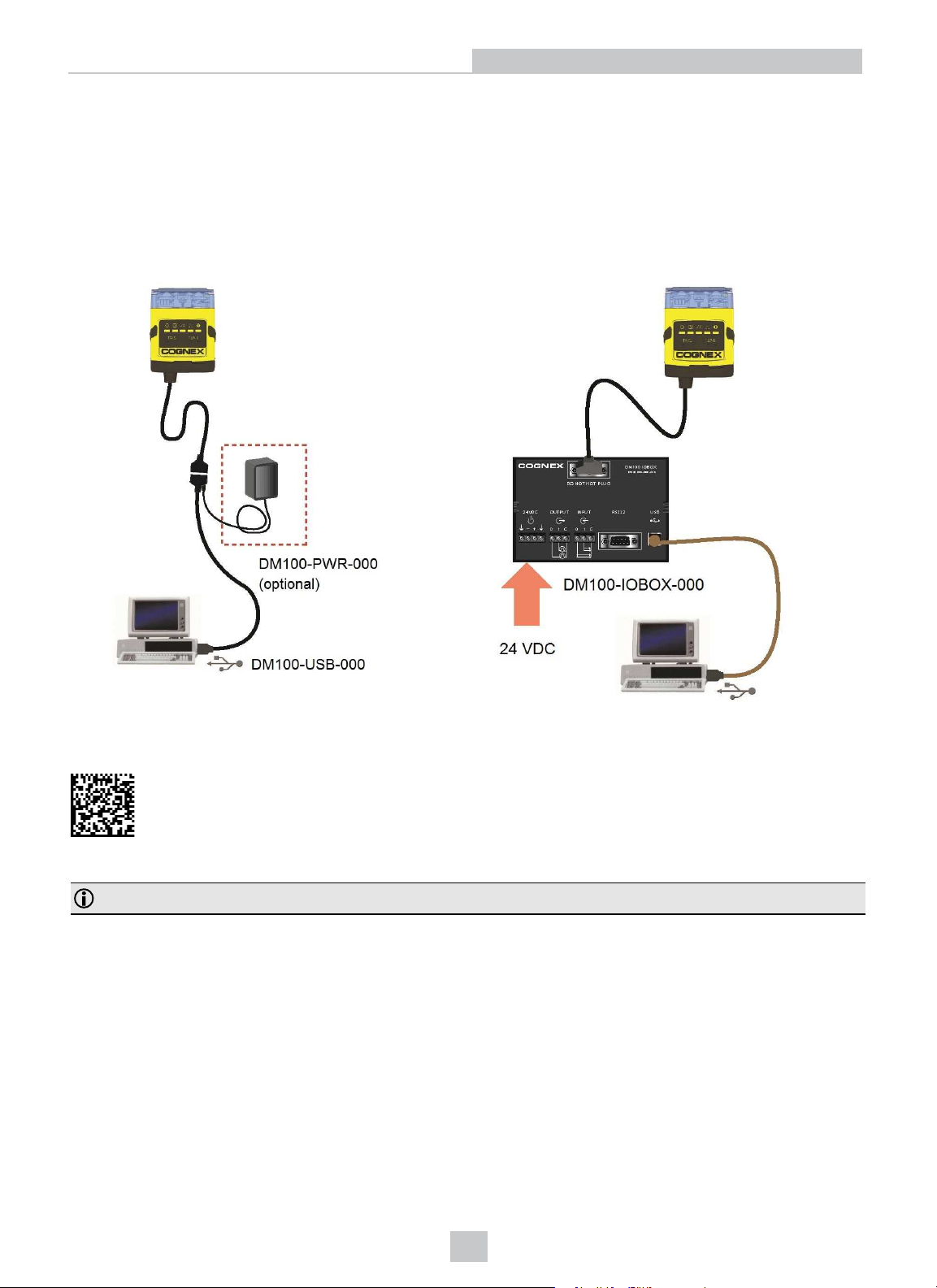
When connected to a PC over USB, the DataMan 150 appears as a COM port. You can connect your device to the
computer in the following ways:
1. Connect directly to the PC: 2. Connect to the PC through a basic I/O module:
If the reader is configured as an HID device and you want to return to USB serial, scan the USBserial connection code:
Note: The DataMan PC software must be installed for this connection type!
27
Page 28
Setting Up Your DataMan
RS-232 Connections
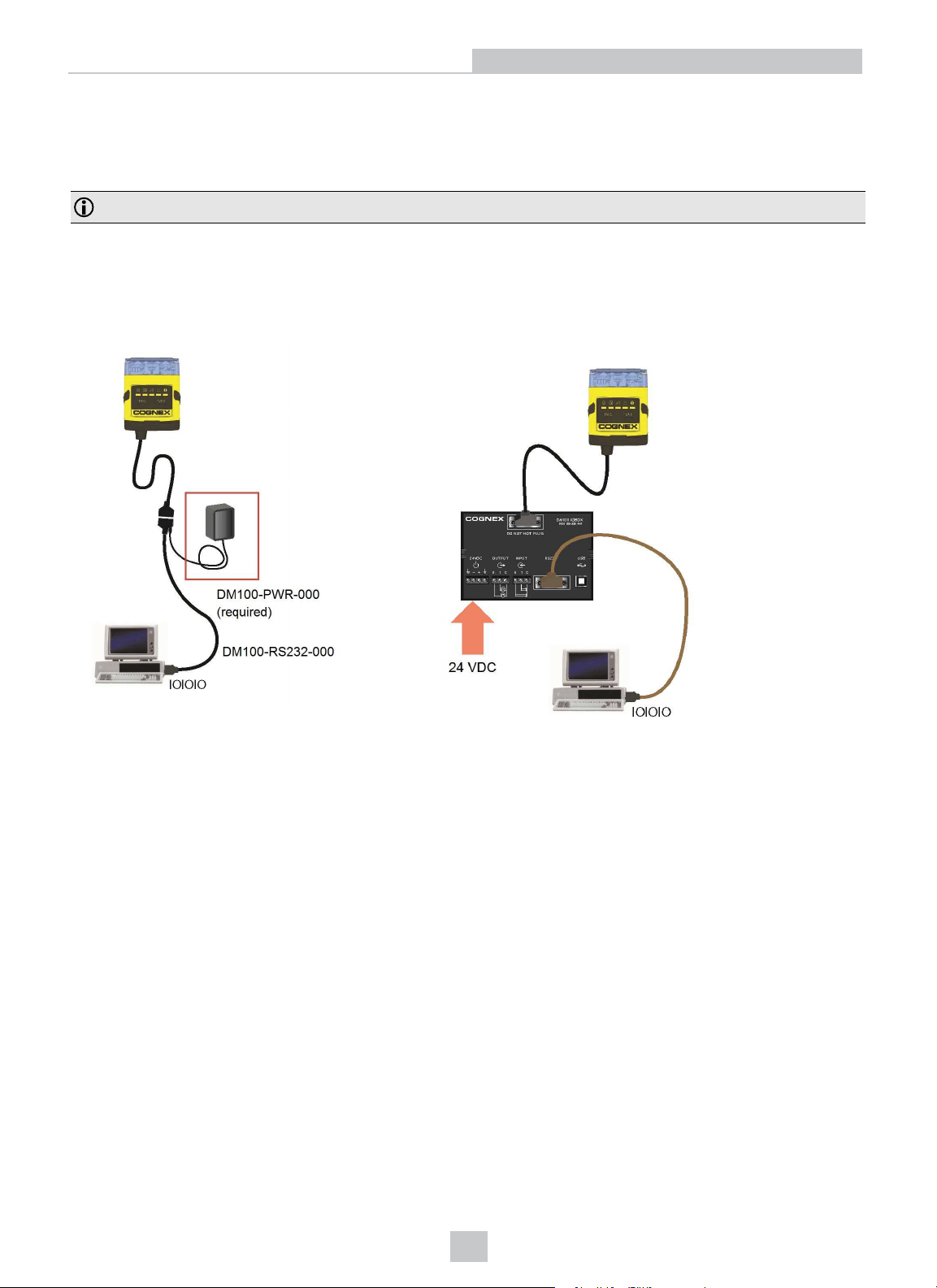
You can connect the DataMan 150 reader to a PC or other device over a standard RS-232 serial connection.
Note: You must supply external power to use this connection type.
You can make a connection in the following ways:
1. Connect directly to the PC: 2. Connect to the PC through a basic I/O module:
28
Page 29
Setting Up Your DataMan
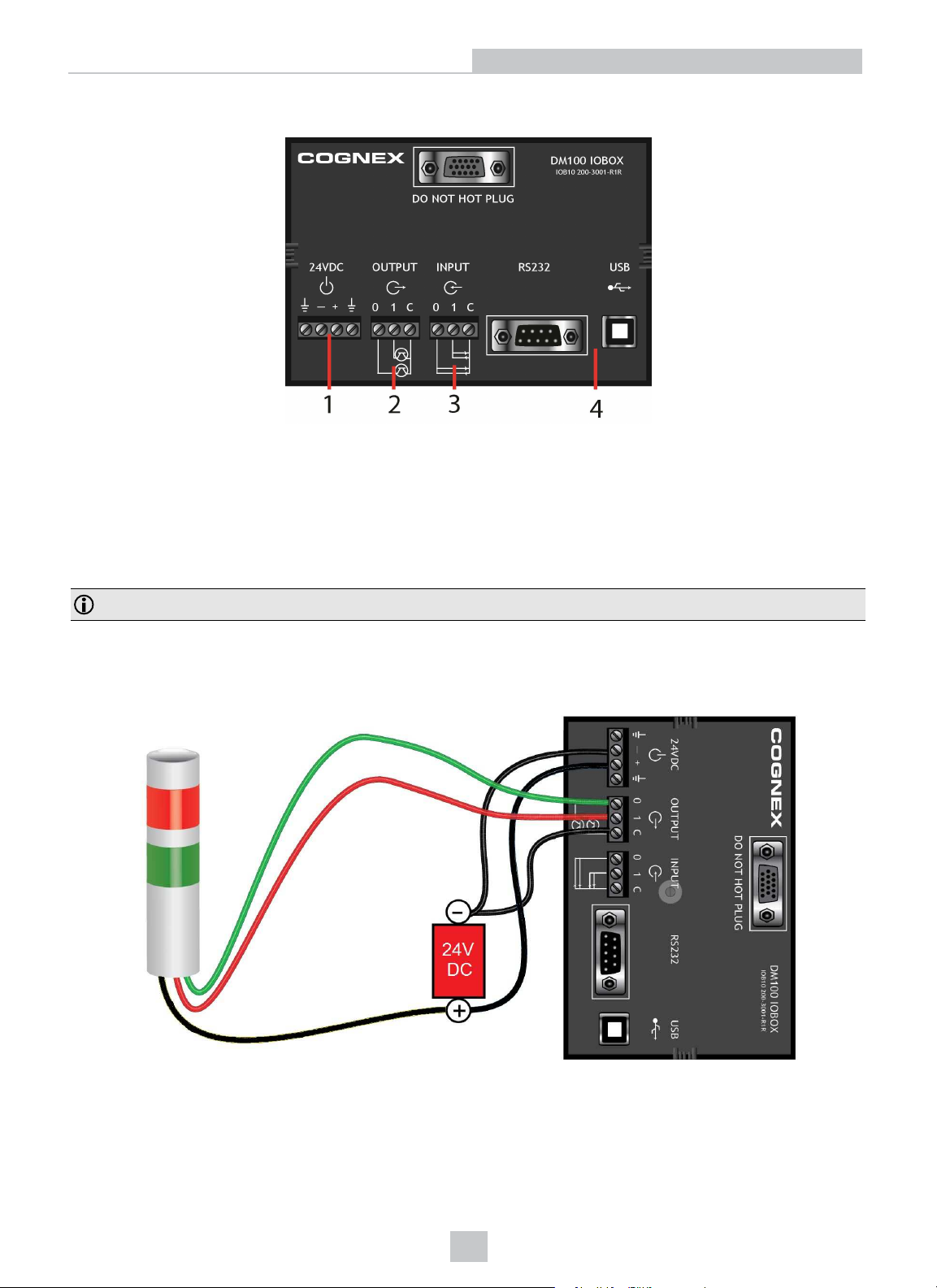
Wiring the Basic I/O Module
1. Power: 5-24 VDC, 2.5W peak. Connect either ground pin to chassis ground.
2. Discrete output: Opto-isolated, current source or sink, depending on wiring; must connect logical ground to
common. Outputs are opto-isolated and protected against reverse polarity. Max current 50 mA @ 24 VDC. Output
1 used for external illumination control by default.
3. Trigger input: Opto-isolated, polarity-independent, current source or sink; have reference to a separated
common signal. Work with ±10-30V. Input 0 is dedicated trigger line.
Note: You must use a null modem cable when connecting the Basic I/O Module to a PC’s RS-232 serial port.
Output Wiring Example
29
Page 30
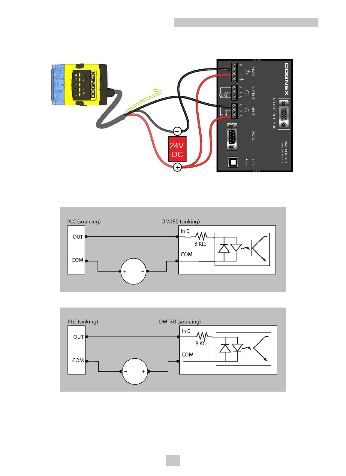
Input Wiring Example
Digital Input Wiring Diagrams
Setting Up Your DataMan
Current Sink Configuration
Current Source Configuration
30
Page 31
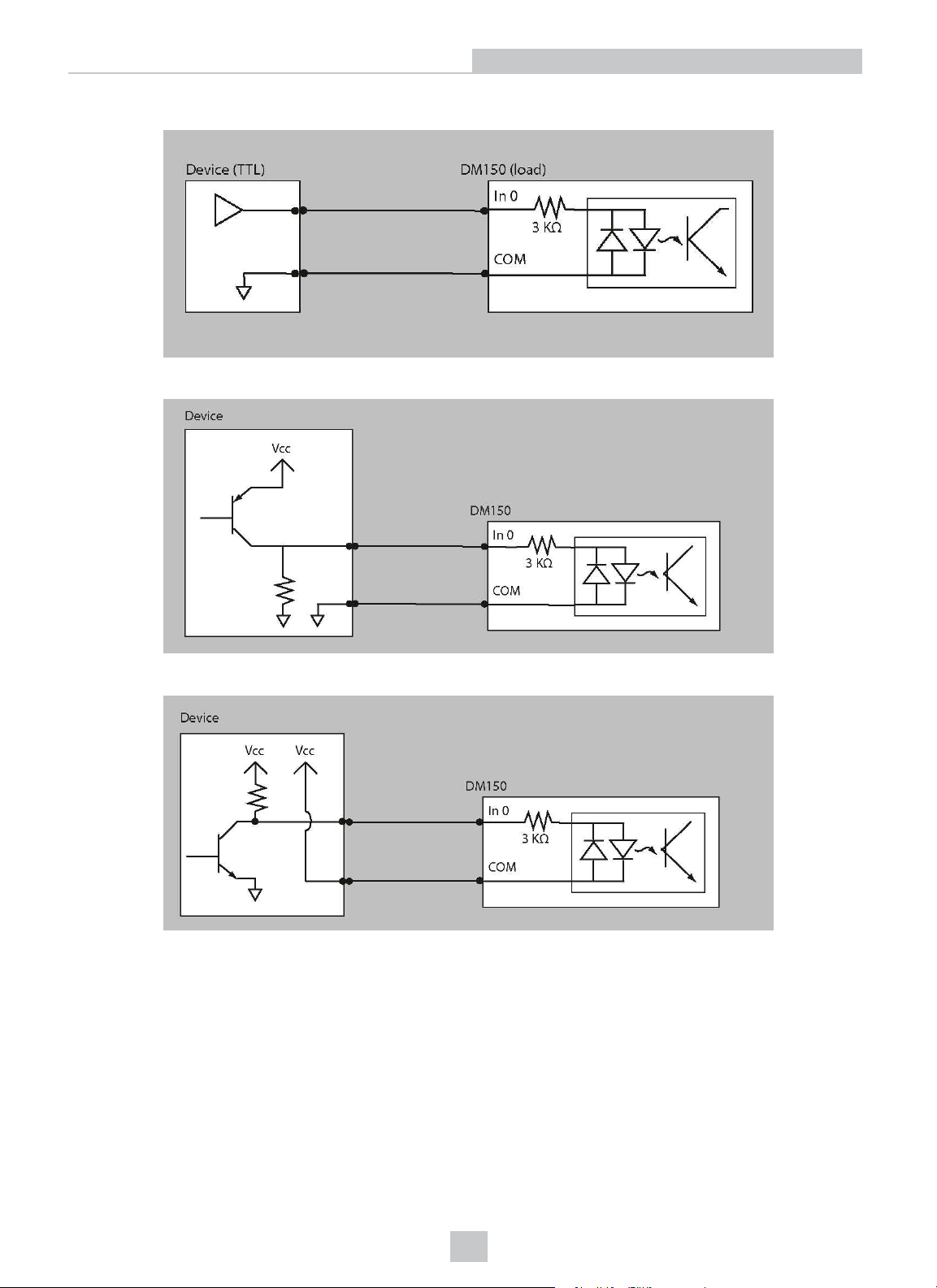
Load to a TTLBuffer
PNPConfiguration
Setting Up Your DataMan
NPNConfigutation
31
Page 32
Setting Up Your DataMan
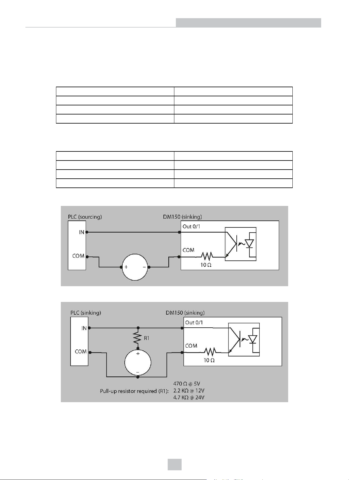
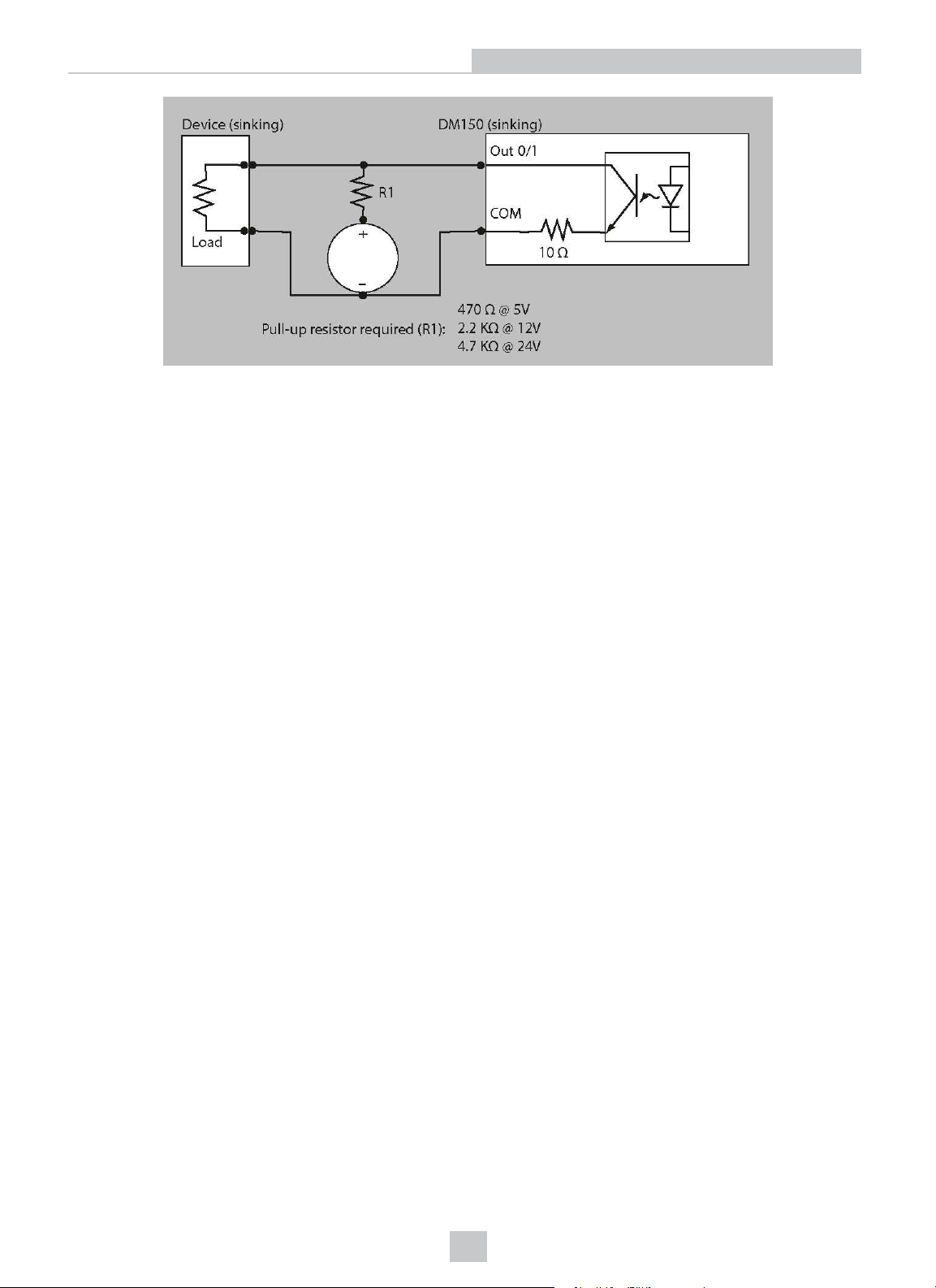
Digital Output Wiring Diagrams
The digital outputs can be used as either NPN (pull-down) or PNP (pull-up) lines. For NPN lines, the external load
should be connected between the output and the positive supply voltage (<26V). The outputs pull down to less than 3V
when ON, which causes current to flow through the load. When the outputs are OFF, no current flows through the load.
NPN (pull down) output type characteristics are the following:
Applied voltage 26 VDC or less
Residual voltage 0.85 V or less
Maximum sink current 100 mA
Overcurrent protection multifuse - 160 mA
PNP (pull up) output type characteristics are the following:
Output voltage range 26 V or less
Residual voltage 0.8 V or less
Maximum source current 100 mA
Overcurrent protection multifuse - 160 mA
Sinking Outputs, Sourcing Inputs
Sinking Outputs, Sinking Inputs
32
Page 33
Setting Up Your DataMan
33
Page 34

Setting Up Your DataMan
Installing the DataMan Software
Perform the following steps to install DataMan Setup Tool:
1. Check the DataMan Release Notes for a full list of system requirements.
2. Download the DataMan Setup Tool from http://www.cognex.com/support/dataman and follow the on-screen
steps.
3. Connect the DataMan 150 to your PC.
4. Choose Start->Programs->Cognex->DataMan Software vx.x.x->Setup Tool to launch Setup Tool. Detected
readers will appear under COM ports.
5. Click Refresh to update the list of connected devices.
6. Select a COM port that lists DataMan 150 and click Connect.
34
Page 35
Setting Up Your DataMan
Setting the Focus Position
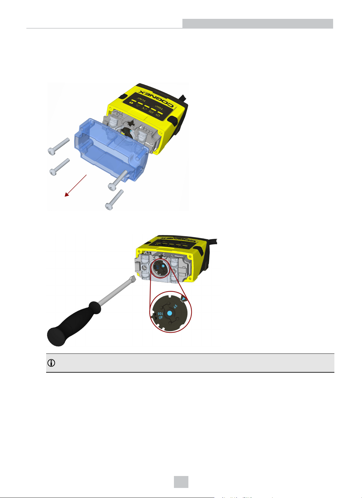
DataMan 150 can operate in one of three distance ranges. Follow the steps below to set the focus position.
1. Remove the screws and the front cover.
2. Using a flathead screwdriver, set the focus position from the front. Always turn clockwise to focus to a larger
distance and counterclockwise to focus to a shorter distance.
Note: If an optical filter has been mounted, first disconnect the DataMan 150 reader from power and remove
the illumination module with the filter before adjusting the focus.
35
Page 36
Setting Up Your DataMan
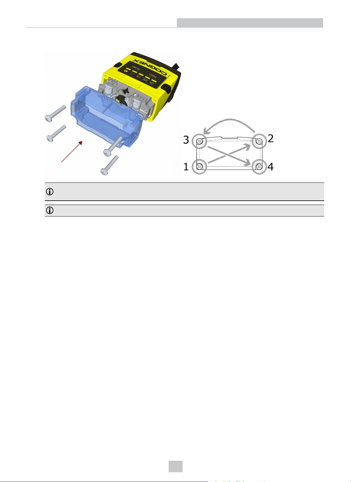
3. Remount the front cover. Observing the tightening sequence below, tighten all four screws to 9 Ncm using a
torque wrench.
4.
Note: If you use an optical filter and the illumination was removed, remount the illumination module first and
then remount the front cover.
5.
Note: The rib in the front cover must be oriented to the top side.
36
Page 37
Setting Up Your DataMan
Field of View and Reading Distances
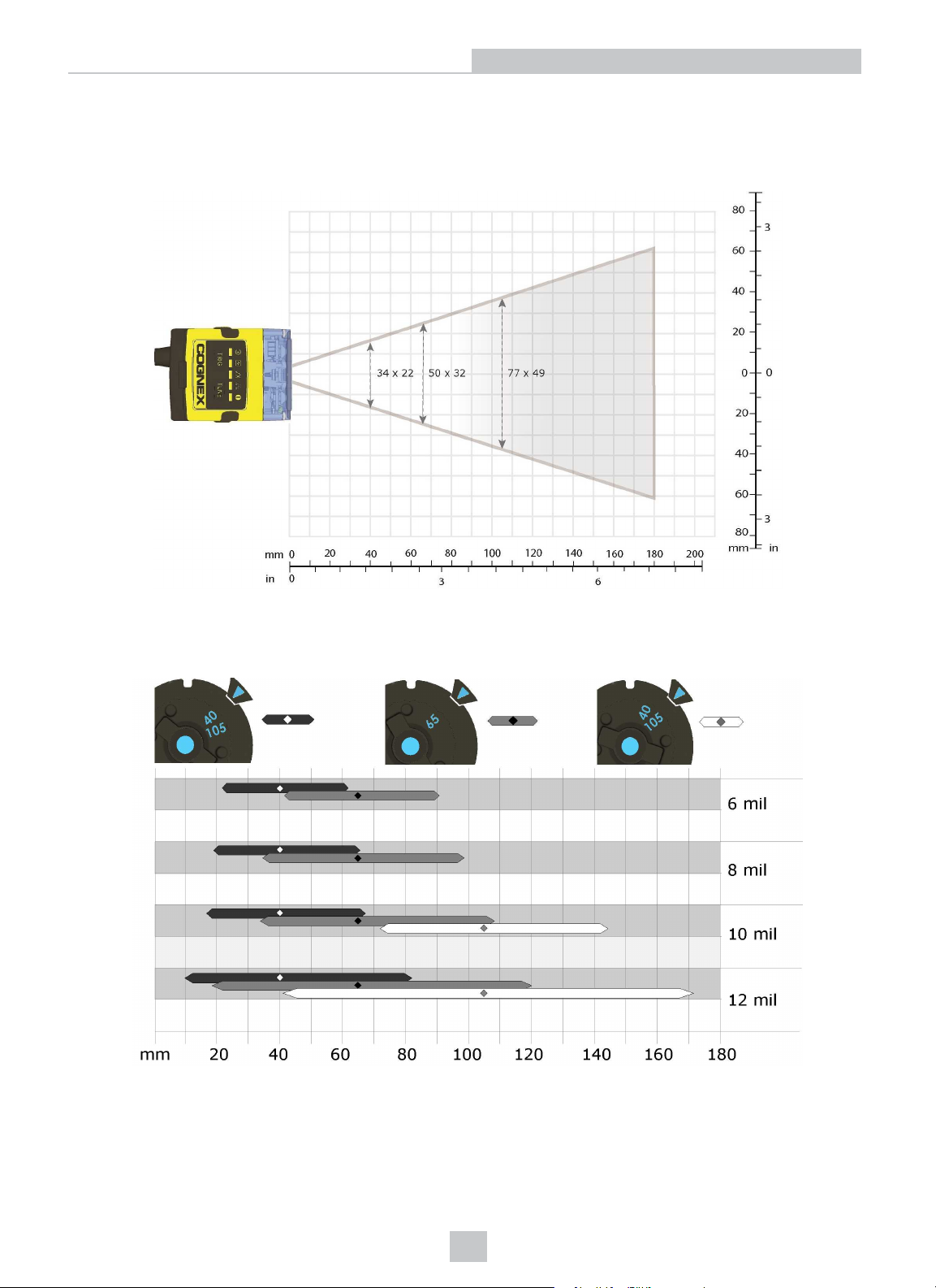
The following chart shows the horizontal field of view for DataMan 150 at a range of working distances.
The horizontal and vertical field of view is shown for working distances of 40 mm, 65 mm and 105 mm.
The chart below shows the supported range of reading distances for four code sizes (6, 8, 10, and 12 mil) at each of the
three focus positions (40 mm, 65 mm, and 105 mm).
The working distances for DataMan 150 are shown in the figure.
37
Page 38
Setting Up Your DataMan
External Triggering and Trigger Modes
If you are using external triggering, you can use any of the following methods to trigger your DataMan 150 reader:
Press the Trigger button ( ) on the reader.
1.
2. Send a pulse on Input-0 line.
3. Send a serial trigger command over the serial line. (You must use RS-232 or USB communications type.)
Click the Trigger button ( ) or press <Ctrl>-T in DataMan Setup Tool.
4.
DataMan 150 supports a variety of trigger modes:
l Single: Acquires a single image and attempts to decode any symbol it contains or more than one symbol in cases
where multicode is enabled. The reader relies on an external trigger source.
l Presentation: Repeatedly scans for a symbol and decodes it whenever one is detected. The reader relies on an
internal timing mechanism to acquire images.
l Manual (default): Begins acquiring images when you press the trigger button on the reader or the discrete trigger
input is activated, and continues acquiring images until a symbol is found and decoded or you release the button
or the discrete trigger input is deactivated.
l Burst: Performs multiple image acquisitions based on an external trigger and decodes one or multiple symbols
appearing in the sequence of images.
l Self: Similar to Presentation mode in that the reader perpetually scans for symbols and decodes them each time
one is detected. Unlike Presentation mode, however, Self mode supports multicode results and a decode attempt
occurs with every image. The main difference between Self and Presentation is the fixed and exact interval for
image acquisitions in Self.
l Continuous: Begins acquiring images based on a single external trigger and continues to acquire images until a
symbol is found and decoded, or until multiple images containing as many codes as specified in multicode mode
are located, or until the trigger is released.
Training and Trigger Modes
Training is supported for the following trigger modes:
l Single trigger
l Burst mode
l Self trigger
l Continuous mode
Training
Training your reader with the expected symbology may help increase decode yield.
To train your reader, place a code in front of the reader and do one of the following:
Press and hold the trigger button ( ) for at least 3 seconds and then release it.
l
Click and hold the trigger button in Setup Tool ( ) for at least 3 seconds and then release it.
l
l Click Train Code in the Action ribbon of DataMan Setup Tool.
If using Single trigger mode, upload the code through File -> Train Image.
38
Page 39
Setting Up Your DataMan
Note: You can use training in Single, Burst, Continuous or Self trigger modes. Only a single symbol of each kind of
symbology can be trained per read setup.
DataMan 150 reports the status of the training and brightness optimization operations using its signaling LEDs. The
second LED from left on the reader flashes green to indicate that the reader is currently trained, or yellow to indicate that
it is not trained.
Connect the reader to the Setup Tool to untrain it and allow it to recognize other enabled symbologies.
Incremental Training for Multiple Symbologies
If you want to train the reader to recognize multiple symbologies, you can present a single image showing all the desired
symbologies and perform the training procedure described in the previous section.
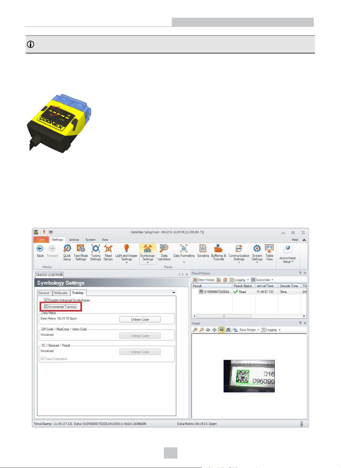
If you cannot present a single image showing all the necessary symbologies, you can enable incremental training on the
Training tab of the Symbology Settings pane:
39
Page 40
Setting Up Your DataMan
With incremental training enabled, you can train the reader using multiple images showing the symbologies you expect
to decode. The reader will train each new symbology while retaining the existing trained symbologies.
Tuning
By tuning, your DataMan 150 reader automatically selects the best settings for the given reading situation, based on
parameters of illumination, camera and decoder properties, and focal distance. Tuning autodiscriminates all enabled
symbologies (both 1-D and 2-D). If multiple symbols are found in the field of view, tuning locks on the first one found. Use
this feature to create an optimum setting to read your codes.
You can use any of the following methods to tune your reader:
Press the Tune button ( ) at least for 3 seconds on your reader. The first press starts the tuning and the second
press cancels the tuning, if it is still ongoing.
Turn on tuning in the DataMan Setup Tool ( ).
Start tuning by sending a DMCC, for more information, see the Command Reference, available through the Windows
Start menu or the Setup ToolHelp menu.
Use Input line 1 for tuning. Go to the System Settings pane in Setup Tool and check Tune. You can also use the In1
button on the toolbar.
Multi-port Connections
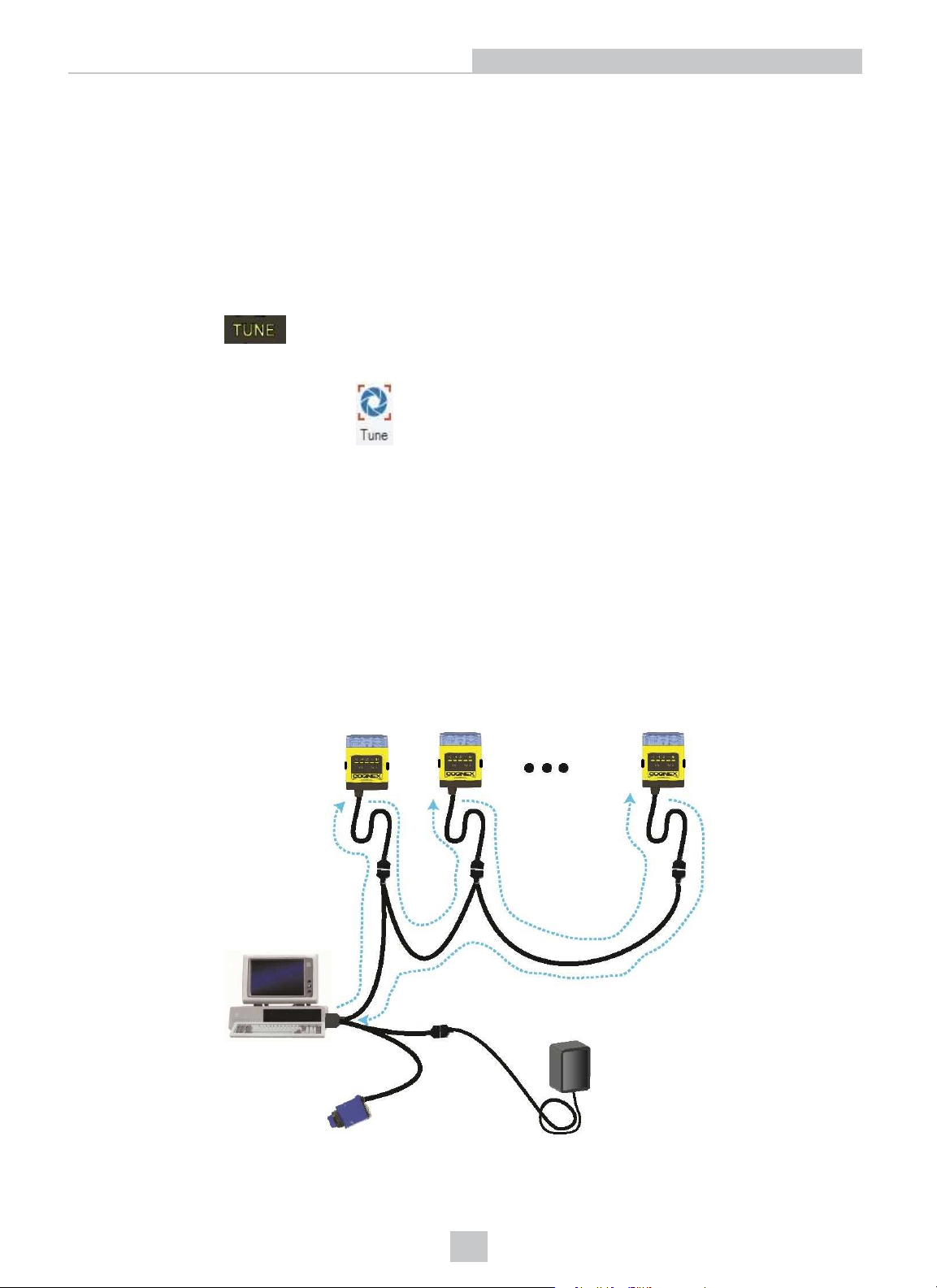
You can connect multiple DataMan 150 readers to a single PC (or other device equipped with a serial port) using a
multi-port connection.
A multi-port connection creates a daisy-chain of readers. Each reader receives serial data from the previous reader and
transmits it to the next reader. When a reader transmits data, it is passed through each of the readers in the chain
between it and the PC.
You must construct your own cable that meets the requirements of your system configuration.
40
Page 41
Setting Up Your DataMan
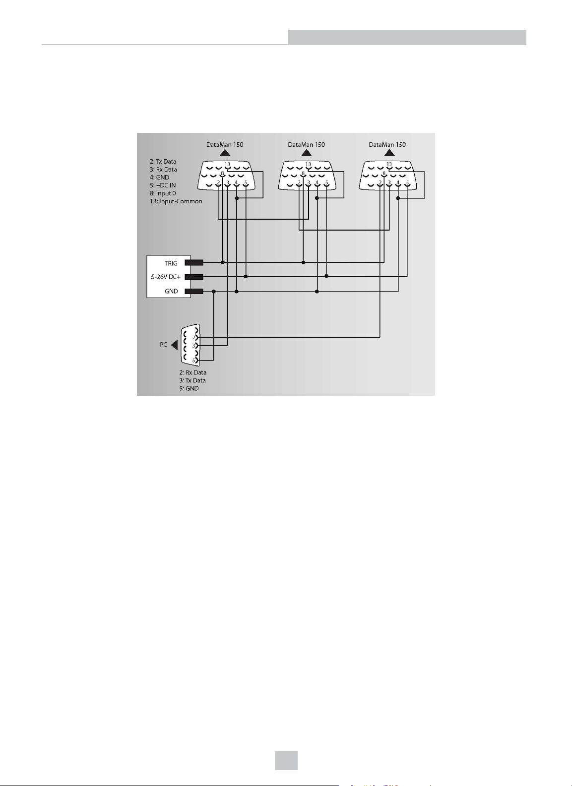
The cable must provide a DB-15 connector for each DataMan 150 and a DB-9 connector for the PC serial port. Each DB15 connector must provide Tx Data, Rx Data, Trigger (Input 0), ground, and DC power. The Tx Data and Rx Data pins on
adjacent connectors must be connected to provide the multi-port connection.
The following diagram shows how to create a multi-port cable for a 3-reader system. In the example, all the readers
share a common trigger. It is also possible to wire individual triggers for each reader.
You must connect each DataMan 150 to DataMan Setup Tool using a USB connection and set the DataMan for multiport operation. To configure a DataMan 150 for multi-port operation, click on the Enable Multi-Port (RS-232 Sharing)
check box in Communication Settings.
There is no guaranteed delivery order when multiple readers transmit data using a multi-port connection; read results
may arrive at the PC in any order. You can configure each DataMan 150 reader in a multi-port connection to add
identifying data to each read result. Your PC application can then determine which reader produced a specific read
result.
To do this, check the Standard Formatting Enabled box (for each symbology that you are using) in Data Formatting,
and enter text in the Leading Text field. (You can also add trailing text by entering text in the Trailing Text field.)
You can obtain the best results when using multi-port connections by keeping the following usage guidelines in mind as
you design your system:
l The maximum cable length between any two DataMan 150 readers or between the PC and any DataMan reader
should be no greater than 15 meters.
l There is no fixed limit to the number of DataMan 150 readers that you can connect to a single PC. Each reader
introduces a delay of about 100 ms when it retransmits received serial data. If you have 5 readers, this means
that there will be a 400 ms delay between the time the first reader in the chain transmits data and the PC receives
it.
l Each DataMan 150 reader must receive a hardware trigger signal on its Input 0 line. You can wire the input ports
to a common trigger signal or you can provide individual triggers for each reader.
41
Page 42

Setting Up Your DataMan
l Each DataMan 150 reader must be individually configured for multi-port operation, and you must perform this
configuration using a USB connection.
l If any reader in the multi-port chain loses power or becomes disconnected, then no data from any other reader
will be transmitted.
l If a DataMan 150 is transmitting its own read result, it will buffer any data received from another reader until it has
finished its own data transmission. If a DataMan 150 is transmitting another reader’s data, it will buffer its own
data if it receives a trigger signal while it is processing the other reader’s data.
l If you use a single power supply for multiple readers, make sure that the power supply can provide enough
power for all of the readers.
42
Page 43
DataMan 150 Specifications
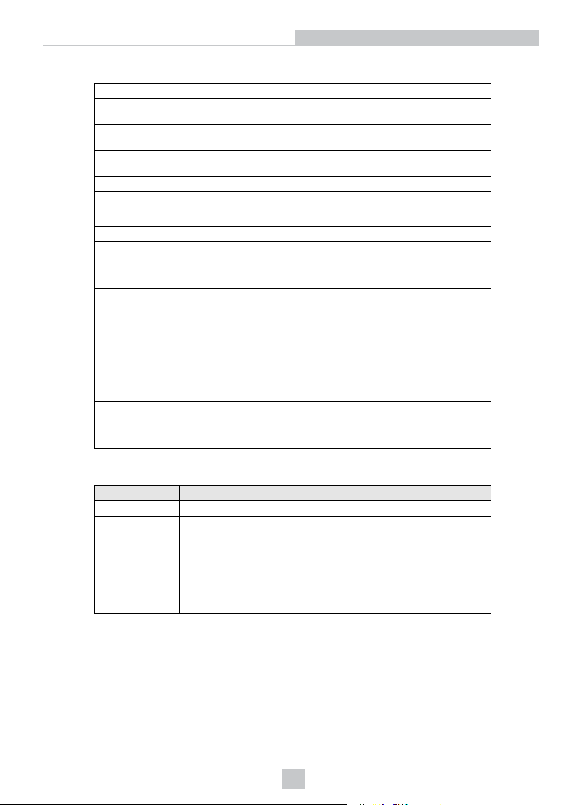
Weight 128 g
Operating
Temperature
Storage
Temperature
Maximum
Humidity
Environmental IP65
Shock and
Vibration
RS-232 RxD, TxD according to TIA/EIA-232-F
Codes Data MatrixTM(IDMax: ECC 0, 50, 80, 100, 140, and 200; IDQuick: ECC200)
Discrete I/O
operating
Limits
• IEC 60068-2-6: vibration test in each of the three main axis for 2 hours @ 10
• IEC 60068-2-27: 1000 shocks, semi-sinusoidal, 11g, 10ms
Gs (10 to 500 Hz at 100m/s2 / 15mm)
QR Code and microQR Code UPC/EAN/JAN Codabar, Interleaved 2 of 5,
Code 25, Code 39, Code 128, and Code 93, Pharma, Postal, RSS/CS, PDF
417, MicroPDF 417, AztecCode, DotCode, MaxiCode, MSI
HS Output 0,1
0ºC — 40ºC (32ºF — 104ºF)
-10ºC — 60ºC (-14ºF — 140ºF)
<95% (non-condensing)
MAX
I
MAX
R
@ 24 VDC 100 mA
@ 12 VDC 200 Ω
@ 24 VDC 500 Ω
Setting Up Your DataMan
Power Supply
Requirements
Imager Specifications
Specification DataMan 150 Imager DataMan 152 Imager
Image Sensor 1/3 inch CMOS 1/3 inch CMOS
Image Sensor
Properties
Image Resolution
(pixels)
Lens Type
4.51 mm x 2.88 mm (W x H), 6.0 μm
square pixels
752 x 480 1280 x 960
S-mount 6.2 mm F:5 (with optional
liquid lens)
S-mount 16 mm F:7 (with optional
liquid lens)
Input 0 (Trigger)
Input 1
5 VDC (2.5 W maximum ) when powered over USB
5 VDC (3W maximum) with external power supply
LPS or NEC class 2 power supply
IH
V
V
TYP
I
IL
±10 — ±25 V
0 — ±2 V
@ 12 VDC 3.6 mA
@ 24 VDC 7.5 mA
3.75 μm square pixels
S-mount 6.2 mm F:5 (with optional
liquid lens)
S-mount 16 mm F:7 (with optional
liquid lens)
43
Page 44
Precautions
Precautions
CAUTION: This device requires the use of an LPS or NEC class 2 power supply.
CAUTION: Do not connect or disconnect this device from the I/O module or 15-pin USB adapter cable while the I/O
module or adapter cable is connected to a PC .
Note: For product support, contact http://support.cognex.com
Observe these precautions when installing the Cognex product, to reduce the risk of injury or equipment damage:
l To reduce the risk of damage or malfunction due to over-voltage, line noise, electrostatic discharge (ESD), power
surges, or other irregularities in the power supply, route all cables and wires away from high-voltage power
sources.
l Changes or modifications not expressly approved by the party responsible for regulatory compliance could void
the user’s authority to operate the equipment.
l Cable shielding can be degraded or cables can be damaged or wear out more quickly if a service loop or bend
radius is tighter than 10X the cable diameter. The bend radius must be at least six inches from the connector.
l Class A Equipment (broadcasting and communication equipment for office work): Seller and user shall be
notified that this equipment is suitable for electromagnetic equipment for office work (Class A) and can be used
outside the home.
l This device should be used in accordance with the instructions in this manual.
l All specifications are for reference purpose only and may be changed without notice.
44
Page 45
Regulations/Conformity
Regulations/Conformity
The DataMan 150 meets or exceeds the requirements of all applicable standards organizations for safe operation.
However, as with any electrical equipment, the best way to ensure safe operation is to operate them according to the
agency guidelines that follow. Please read these guidelines carefully before using your device.
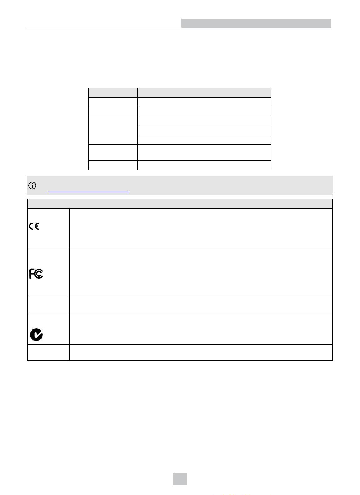
Regulator Specification
USA FCC 47 CFR Part 15 Subpart B, Class A
Canada ICES-003
European
Community
Australia C-TICK, AS/NZS CISPR 22 / EN 55022 for Class A
Japan J55022, Class A
Note: For the most up-to-date regulations and conformity information, please refer to the Cognex online support
site: http://www.cognex.com/Support.
European
Compliance
FCC Class A
Compliance
Statement
Canadian
Compliance
C-Tick
Statement
The CE mark on the product indicates that the system has been tested to and conforms with the
provisions noted within the 2004/108/EC Electromagnetic Compatibility Directive and the 2006/95/EC
Low Voltage Directive. For further information please contact: Cognex Corporation, One Vision Drive
Natick, MA 01760 USA.
Cognex Corporation shall not be liable for use of our product with equipment (i.e., power supplies,
personal computers, etc.) that is not CE marked and does not comply with the Low Voltage Directive.
This equipment has been tested and found to comply with the limits for a Class A digital device,
pursuant to Part 15 of the FCC rules. These limits are designed to provide reasonable protection
against harmful interference when the equipment is operated in a commercial environment. This
equipment generates, uses, and can radiate radio frequency energy and, if not installed and used in
accordance with the instructions, may cause harmful interference to radio communications. Operation
of this equipment in a residential area is likely to cause harmful interference, in which case the user
will be required to correct the interference at personal expense.
This Class A digital apparatus complies with Canadian ICES-003. Cet appareil numérique de la
classe A est conforme à la norme NMB-003 du Canada.
Conforms to AS/NZS CISPR 22/ EN 55022 for Class A Equipment.
EN55022 (CISPR 22) Class A
EN55024:1998 +A1:2001 +A2: 2003
EN60950
Equipment
Safety and Regulatory
UL and cUL
Statement
UL and cUL listed: UL60950-1 1st ed. and CSA C22.2 No.60950-1 1st ed. Certified to CB scheme IEC
60950-1:2001 1st ed.
For European Community Users
Cognex complies with Directive 2002/96/EC OF THE EUROPEAN PARLIAMENT AND OF THE COUNCIL of 27 January
2003 on waste electrical and electronic equipment (WEEE).
This product has required the extraction and use of natural resources for its production. It may contain hazardous
substances that could impact health and the environment, if not properly disposed.
In order to avoid the dissemination of those substances in our environment and to diminish the pressure on the natural
resources, we encourage you to use the appropriate take-back systems for product disposal. Those systems will reuse or
recycle most of the materials of the product you are disposing in a sound way.
45
Page 46
Regulations/Conformity
The crossed out wheeled bin symbol informs you that the product should not be disposed of along with municipal
waste and invites you to use the appropriate separate take-back systems for product disposal.
If you need more information on the collection, reuse, and recycling systems, please contact your local or regional waste
administration.
You may also contact your supplier for more information on the environmental performance of this product.
46
Page 47

 Loading...