

Page 1
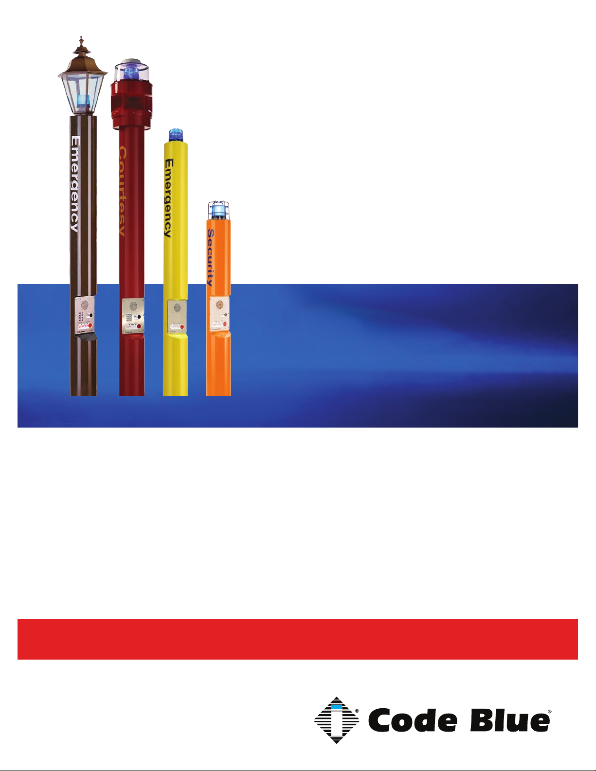
CB 5 Series
CB 5-s with Public Address
CB 5-s with Decorative Top
Installation, Configuration, Operation & Troubleshooting
CB 5-s
CB 5-p
Administrator Guide
800.205.7186 • www.codeblue.com
Page 2

CB 5 Series
Administrator Guide
WARNING
ONLY QUALIFIED PERSONNEL SHOULD INSTALL THESE UNITS. THE INSTALLATION
SHOULD CONFORM TO ALL LOCAL CODES. IN SOME COUNTRIES, A CERTIFIED ELECTRICIAN MAY BE REQUIRED.
NOTICE TO USERS
Copyright © Code Blue Corporation. All rights reserved. This guide or software described herein, in
whole or part, shall not be reproduced, translated or reduced to any machine-readable form without
prior written approval from Code Blue Corporation.
CODE BLUE CORPORATION PROVIDES NO WARRANTY WITH REGARD TO THIS GUIDE, THE
SOFTWARE OR OTHER INFORMATION CONTAINED HEREIN AND HEREBY EXPRESSLY DISCLAIMS ANY IMPLIED WARRANTIES OF MERCHANTABILITY OR FITNESS FOR ANY PARTICULAR PURPOSE WITH REGARD TO THIS GUIDE, THE SOFTWARE OR SUCH OTHER INFORMATION. IN NO EVENT SHALL CODE BLUE CORPORATION BE LIABLE FOR ANY INCIDENTAL,
CONSEQUENTIAL, OR SPECIAL DAMAGES, WHETHER BASED ON TORT, CONTRACT, OR
OTHERWISE, ARISING OUT OF OR IN CONNECTIONS WITH THIS GUIDE, THE SOFTWARE
OR OTHER INFORMATION CONTAINED HEREIN OR THE USE THEREOF.
Code Blue Corporation reserves the right to make any modications to this guide or the information
contained herein at any time without notice. The software described herein may also be governed
by the terms of a separate user license agreement.
Code Blue® is a registered trademark of Code Blue Corporation.
Code Blue • 259 Hedcor Street • Holland, MI 49423 USA • 800.205.7186 • www.codeblue.com
GU-158-Dpage 2 of 42
Page 3

Administrator Guide
Table of Contents
Section Page
2 Introduction.................................................................................... 4
3 Getting Started............................................................................... 6
4 Spare Parts..................................................................................... 8
5 Power Requirements......................................................................10
6 Software Conguration..................................................................12
7 CB 5-s Low Voltage Exploded View..............................................13
8 CB 5-s High Voltage Exploded View.............................................14
9 CB 5-p Low Voltage Exploded View..............................................15
10 CB 5-p High Voltage Exploded View.............................................16
CB 5 Series
11 CB 5-s with Decorative Top Low Voltage Exploded View...........17
12 CB 5-s with Decorative Top High Voltage Exploded View..........18
13 CB 5-s and CB 5-p Installation Instructions................................19
14 CB 5 Series Tower Base Gasket Installation Instructions..........21
15 CB 5-s with Public Address Installation Instructions.................23
16 CB 5-s with Decorative Top Installation Instructions.................24
17 CB 5 Series Anchor Bolt Installation Instructions......................26
18 CB 5 Overhead Camera Mount Installation Instructions............27
19 S-1000/S-1050 Installation Instructions.......................................29
20 PoE Installation Instructions........................................................31
21 CB 5 Series Deck Mount Installation Instructions......................32
22 CB 5-s and CB 5-p Standard Wiring (with Hammond Transformer)...........33
23 CB 5-s and CB 5-p Standard Wiring (with Multi-tap Power Brick).............34
24 CB 5 Series with Public Address Wiring......................................35
25 Multi Tap Transformer Wiring.......................................................37
26 Maintenance Schedule..................................................................38
27 Locating Unit Serial Numbers.......................................................40
28 Warranty..........................................................................................41
29 Download Information...................................................................42
Code Blue • 259 Hedcor Street • Holland, MI 49423 USA • 800.205.7186 • www.codeblue.com
GU-158-Dpage 3 of 42
Page 4

CB 5 Series
Administrator Guide
2 Introduction
Thank you for choosing the CB 5 Series for your Code Blue application.
The CB 5 Series Help Points® are the original Code Blue pedestal units that set the industry
standard for rugged construction, full feature availability and high visibility. The CB 5 Series is
easily recognized throughout a full 360-degree area. The high output strobe is easily identiable by
security when activated.
The CB 5 Series is an excellent choice for walkways, parks, college and commercial campus areas,
open landscape areas and anywhere a freestanding pedestal unit is required.
The exclusive analog InterAct and VoIP speakerphones are designed for maximum reliability,
vandal resistance, auxiliary functions, mass notication control, and fault monitoring and reporting
capability. (See IA4100 or IP5000 guides for more information.)
Our unmistakable craftsmanship makes our Help Points® the most rugged on the market,
withstanding the punishment of natural and man-made disasters. With durable construction, our
pedestal units can meet any requirement or purpose. CB 5 Series units have a rugged steel
construction, industrial engineering grade reective graphics and weather, UV and grafti resistant
paint.
Other options include:
• IP and analog phones
• 360° Public Address Speaker (PAS)
• Overhead Camera Mount
• Strobe Cage
Code Blue • 259 Hedcor Street • Holland, MI 49423 USA • 800.205.7186 • www.codeblue.com
GU-158-Dpage 4 of 42
Page 5
CB 5 Series
Administrator Guide
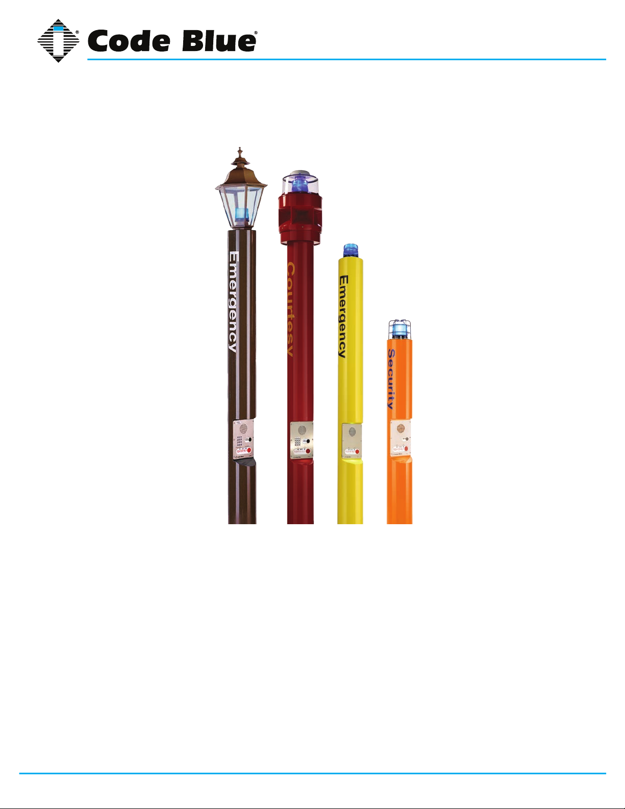
This guide contains all of the CB 5 Series information. This guide contains a general overview of the
CB 5 Series options and its applications, installation and wiring.
CB 5-s with
Decorative Top
Code Blue • 259 Hedcor Street • Holland, MI 49423 USA • 800.205.7186 • www.codeblue.com
Public Address
CB 5-s CB 5-pCB 5-s with
GU-158-Dpage 5 of 42
Page 6
CB 5 Series
Administrator Guide
3 Getting Started
Basic Install Instructions
1. EIA/TIA, ANSI, CSA and BICSI cabling or similar standards shall be adhered to for proper
operation of Code Blue communication devices connected to copper or ber infrastructures.
Communications cable and electrical cable in the same conduit is not an acceptable instal lation and shall not be supported. Analog phones require a minimum of 23mA for proper
operation (26-29mA recommended).
2. Each analog speakerphone requires its own phone line or PBX extension. Multiple units
shall not be supported.
3. Speakerphones require programming before operation. Consult the User Guide or Admin istrator Guide enclosed with the unit or visit www.codeblue.com > Support > Downloads to
read or download manuals.
4. If you are installing IP speakerphones, please read the appropriate manuals and consult
with your Network Administrator.
5. Size electrical wiring based on length of run.
6. Consult the enclosed document packet for internal wiring instructions.
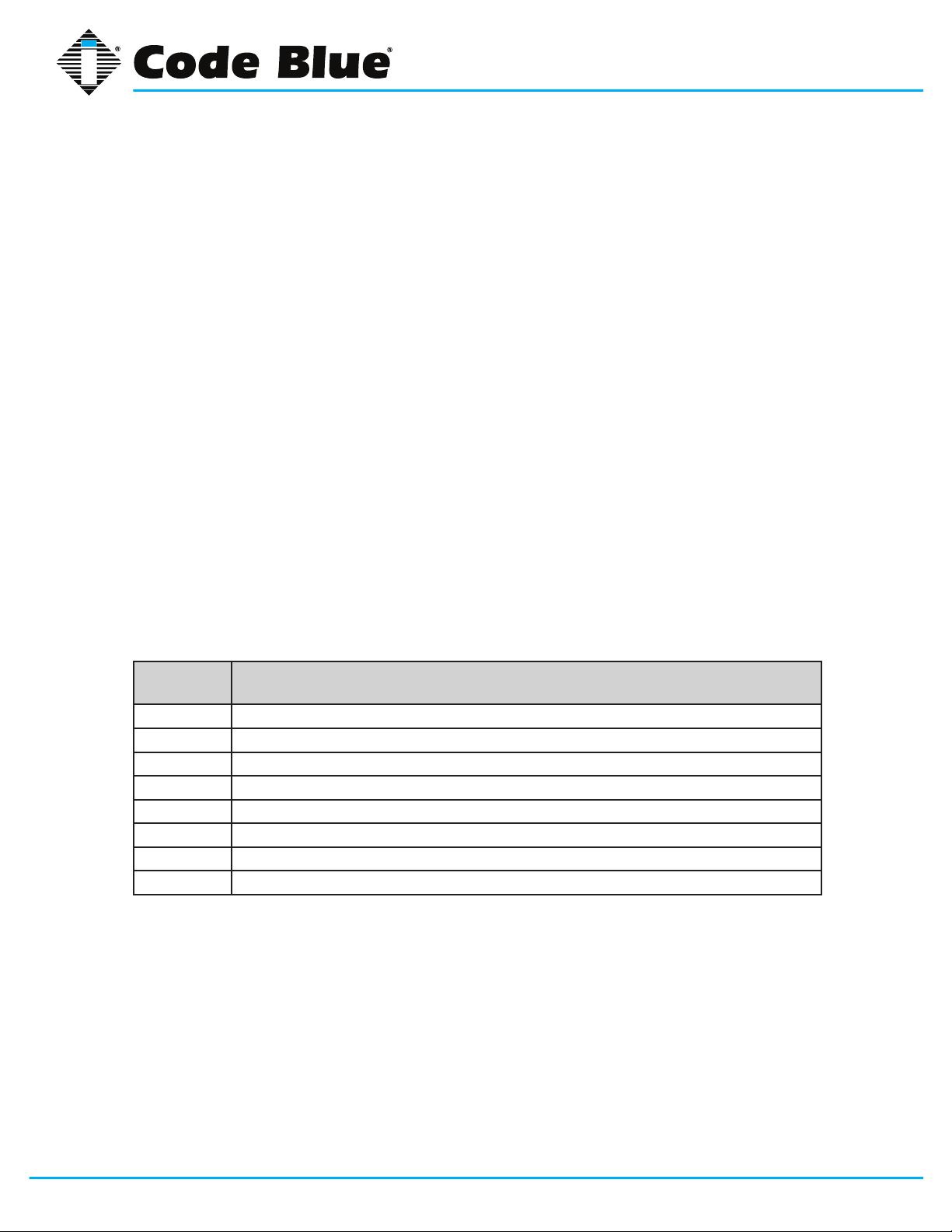
What’s Included
Quantity Part Description
1 Anchor Bolt Kit (3 L-Bolts, 6 Washers, 3 Hex Nuts, 1 Cardboard Template
1 Security Bit
1 Enclosure (CB 5-s, CB 5-p,CB 5-s w/PAS, CB 5-s w/Decorative Top)
2 Access Door Screws
1 URL listing sheet of Installation, Programming, Wiring & Warranty locations
1 PAS Top (PAS Option Only)
1 Dome Top Assembly (Solar not Included)
1 Decorative Top Assembly w/Strobe
Code Blue • 259 Hedcor Street • Holland, MI 49423 USA • 800.205.7186 • www.codeblue.com
GU-158-Dpage 6 of 42
Page 7

CB 5 Series
Administrator Guide
CB 5-s, CB 5-p Tools Required
1. Ladder to reach the top of the units
2. Drill and security bit for removing and inserting security screws on phone, dome top and
access door
3. 11/8 socket set and extension for installing anchor bolts or Deck Mount Kits
4. Phillips head screwdriver and at head screwdriver
CB 5-s with Public Address Tools Required
1. Ladder to reach the top of the units
2. Drill and security bit for removing and inserting security screws on phone and
access door
3. 11/8 socket set and extension for installing anchor bolts
4. Phillips head screwdriver and at head screwdriver
5. 3/8 socket set to mount the mounting plate containing the new toroid transformer
6. 6mm Allen Wrench small black for adapter ring
7. 9/16 inch Wrench for painted ring bolts
CB 5-s with Decorative Top Tools Required
1. Ladder to reach the top of the units
2. Drill and security bit for removing and inserting security screws on phone, dome top and
access door
3. 11/8 socket set and extension for installing anchor bolts
4. Phillips head screwdriver and at head screwdriver
Code Blue • 259 Hedcor Street • Holland, MI 49423 USA • 800.205.7186 • www.codeblue.com
GU-158-Dpage 7 of 42
Page 8
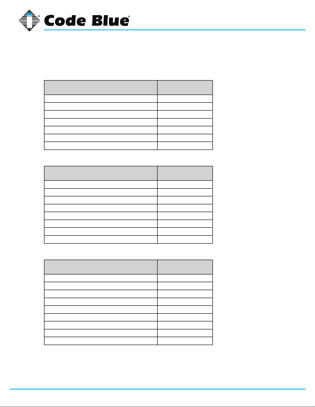
4 Spare Parts
CB 5-s
Part Part Number
LED Strobe Light 40159
LED Faceplate Light 40196
Faceplate Screws 41544 (6pk)
Access Door Screws 41545 (2pk)
Manifold R/B 5-way 40101
Analog Surge Suppressor 41471
IP Surge Suppressor 41421
CB 5-p
Part Part Number
CB 5 Series
Administrator Guide
LED Strobe Light 40159
LED Faceplate Light 40196
Faceplate Screws 41544 (6pk)
Access Door Screws 41545 (2pk)
Manifold R/B 5-way 40101
Analog Surge Suppressor 41471
IP Surge Suppressor 41421
Strobe Guard 44022
CB 5-s with Public Address
Part Part Number
LED Strobe Light 40159
LED Faceplate Light 40196
Faceplate Screws 41544 (6pk)
Access Door Screws 41545 (2pk)
Analog Surge Suppressor 41471
IP Surge Suppressor 41421
PAS Toroid Transformer 41121
Dome Top Lens w/active vent 40007
PAS 120V AMP Assembly 40010
Code Blue • 259 Hedcor Street • Holland, MI 49423 USA • 800.205.7186 • www.codeblue.com
GU-158-Dpage 8 of 42
Page 9
CB 5 Series
Administrator Guide
CB 5-s with Decorative Top
Part Part Number
LED Strobe Light 40159
LED Faceplate Light 40196
Faceplate Screws 41544 (6pk)
Access Door Screws 41545 (2pk)
Manifold R/B 5-way 40101
Analog Surge Suppressor 41471
IP Surge Suppressor 41421
CB 5 Series Additional Options
Part Part Number
Overhead Camera Mount Need Color for Part#
Multi Tap Transformer
Blank Lexan Plate Assembly 40067
Service Plate - Lexan w/graphics (This Location Being Serviced) 40208
Deck Mount Kit 40215
Triad Transformer 40V A 120V
S-1050 LED Strobe Photo Cell 40542
PoE Power Splitter Kit Assembly 41574
IP5000 Speakerphone FP1 50101
IP5000 Speakerphone FP2 50102
IP5000 Speakerphone FP3 50103
(powers accessories) 120V, 240V, 277V, 347V 40104
(will not power accessories) 41246
Code Blue • 259 Hedcor Street • Holland, MI 49423 USA • 800.205.7186 • www.codeblue.com
GU-158-Dpage 9 of 42
Page 10
CB 5 Series
Administrator Guide
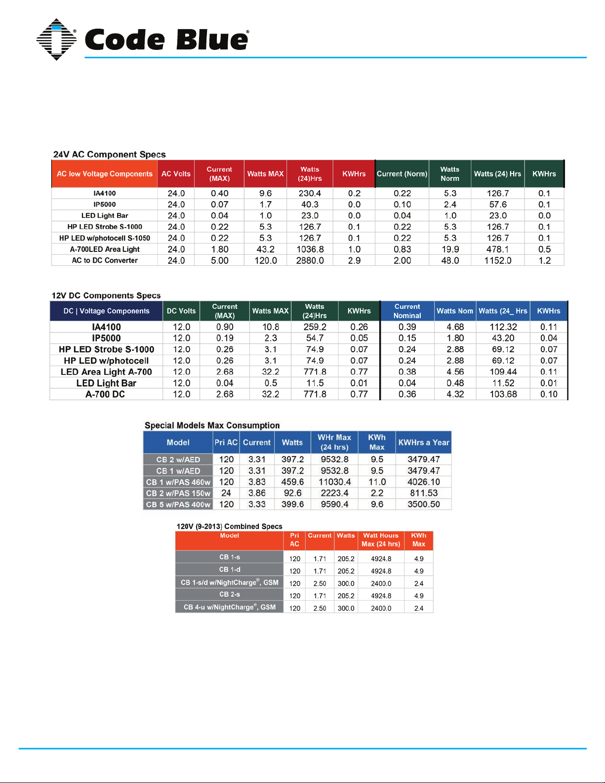
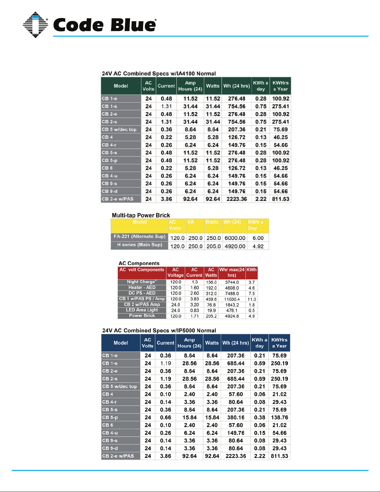
5 Power Requirements
(The following power requirements include the 5 Series and also ALL OTHER Code Blue units.)
Code Blue • 259 Hedcor Street • Holland, MI 49423 USA • 800.205.7186 • www.codeblue.com
GU-158-Dpage 10 of 42
Page 11
CB 5 Series
Administrator Guide
Code Blue • 259 Hedcor Street • Holland, MI 49423 USA • 800.205.7186 • www.codeblue.com
GU-158-Dpage 11 of 42
Page 12

CB 5 Series
Administrator Guide
6 Software Configuration
Blue Alert® MNS Software
Blue Alert MNS (Mass Notication Software) lls a need in the marketplace for an incident response
solution that is both comprehensive and cost-effective, while also providing an efcient way to detect
and respond. The advanced mass notication system allows responders to deliver multi-layered
emergency notications via a wide range of platforms, including email, text message (SMS), emer-
gency phones, public address speakers, social media, desktop alerts and more, quickly informing
and directing people in emergency situations.
Blue Alert® EMS
Blue Alert EMS is an advanced software solution that handles all incoming events effectively by remotely controlling emergency communication devices with an easy-to-use Graphical User Interface
(GUI). You also will have the ability to open gates and AED access doors, turn LED beacon/strobes
on or off, transfer calls to Public Address Systems to make area wide announcements and incorporate other ancillary devices and applications while the system securely archives data for future
reference.
ToolVox®
A sophisticated emergency management platform for your blue light phone network, ToolVox offers
unique real-time monitoring and provisioning options for emergency phones and public address
speakers, effectively acting as a hub for connecting Help Points® and other Code Blue devices. Using our proprietary incident response software, Blue Alert® MNS and EMS, you can send alerts via
outdoor platforms, such as blue light phones and public address speakers. It also provides connections to PBX, public telephone (PSTN) and Internet (ISP) networks, in addition to third party security
platforms.
Code Blue • 259 Hedcor Street • Holland, MI 49423 USA • 800.205.7186 • www.codeblue.com
GU-158-Dpage 12 of 42
Page 13
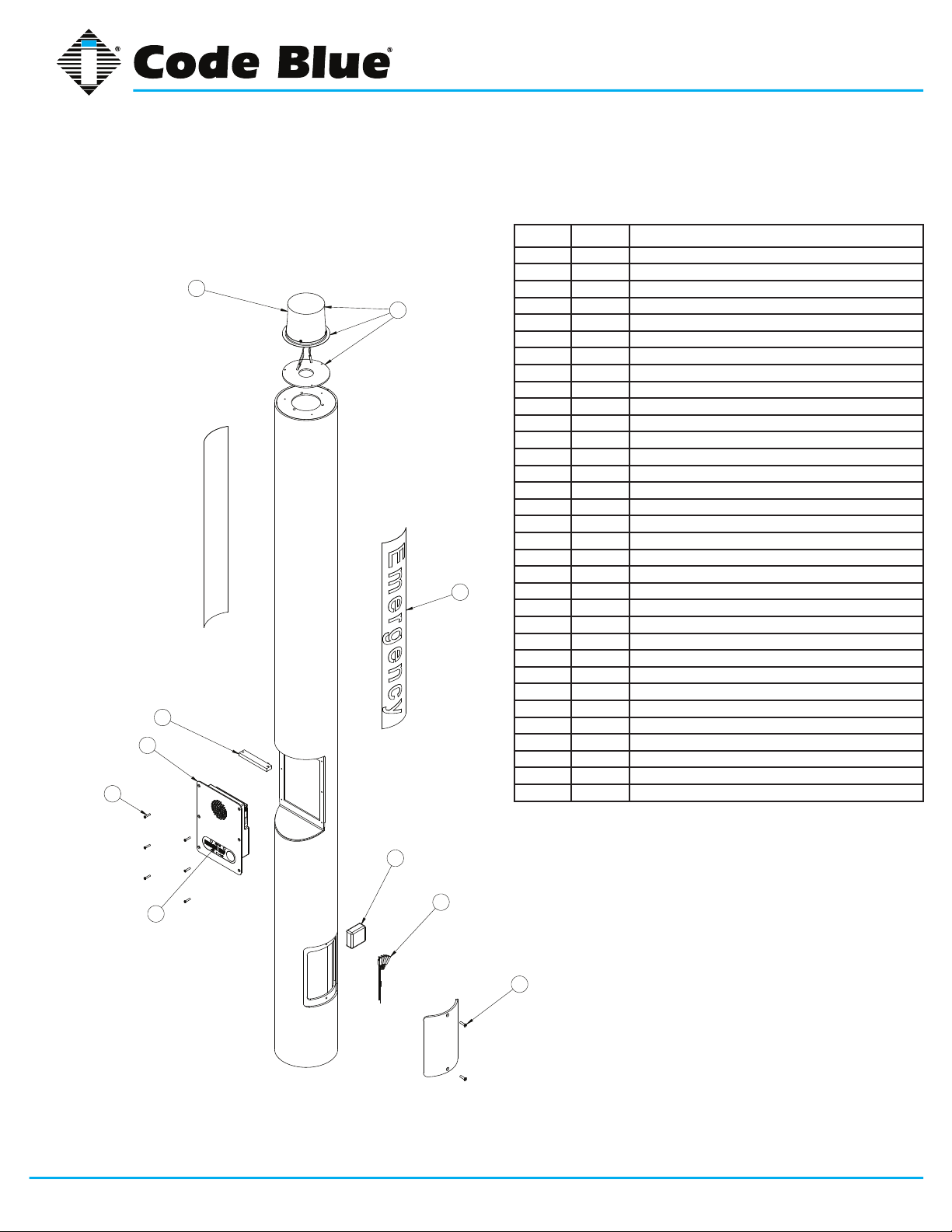
7 CB 5-s Low Voltage Exploded View
2a
2b
1
8
4
7
9
6
3
5
BALL # PART # DESCRIPTION
1 CALL Standard / Custom Graphic
2a 40159 LED Beacon Strobe
2b 40115 Complete LED Beacon Strobe Replacement Kit
3 41471 Analog Surge Suppressor
3 41421 IP Surge Suppressor
4 40101 Manifold R/B 5-way
5 41545 Access Door Security Screws (2 pk)
6 50001 Single Button IA4100 Analog Phone – PUSH FOR HELP
6 50002 Double Button IA4100 Analog Phone – PUSH FOR HELP
6 50003 Keypad IA4100 Analog Phone – PUSH FOR HELP
6 50004 Single Button IA4100 Analog Phone – EMERGENCY
6 50005 Double Button IA4100 Analog Phone – EMERGENCY
6 50006 Keypad IA4100 Analog Phone – EMERGENCY
6 50007 Single Button IA4100 Analog Phone – EMERGENCY/EMERGENCIA
6 50008 Double Button IA4100 Analog Phone – EMERGENCY/EMERGENCIA
6 50009 Keypad IA4100 Analog Phone – EMERGENCY/EMERGENCIA
6 50101 Single Button IP5000 Phone – PUSH FOR HELP
6 50102 Double Button IP5000 Phone – PUSH FOR HELP
6 50103 Keypad IP5000 Phone – PUSH FOR HELP
6 50104 Single Button IP5000 Phone – EMERGENCY
6 50105 Double Button IP5000 Phone – EMERGENCY
6 50106 Keypad IP5000 Phone – EMERGENCY
6 50107 Single Button IP5000 Phone – EMERGENCY/EMERGENCIA
6 50108 Double Button IP5000 Phone – EMERGENCY/EMERGENCIA
6 50109 Keypad IP5000 Phone – EMERGENCY/EMERGENCIA
7 41544 Faceplate Security Screw 10x24 (6 pk)
8 41548 LED Faceplate Light
9 40357 Bezel Assembly IA4100 Analog Phone – PUSH FOR HELP
9 40407 Bezel Assembly IA4100 Analog Phone – EMERGENCY
9 40408 Bezel Assembly IA4100 Analog Phone – EMERGENCY/EMERGENCIA
9 40313 Bezel Assembly IP5000 Analog Phone – PUSH FOR HELP
9 40405 Bezel Assembly IP5000 Analog Phone – EMERGENCY
9 40406 Bezel Assembly IP5000 Analog Phone – EMERGENCY/EMERGENCIA
CB 5 Series
Administrator Guide
DISCLAIMER: Product design and component use subject to change without notice. Product shown reasonably represents current offering and
is intended to assist in component identication. Reference the model and serial number from the unit ID tag and contact manufacturer to conrm
replacement part version and availability.
Code Blue • 259 Hedcor Street • Holland, MI 49423 USA • 800.205.7186 • www.codeblue.com
GU-158-Dpage 13 of 42
Page 14

8 CB 5-s High Voltage Exploded View
2
1
8
4
7
9
6
5
2
3
BALL # PART # DESCRIPTION
1 CALL Standard Graphic
1 CALL Custom Graphic
2 40159 LED Beacon Strobe
2 40115 Complete LED Beacon Strobe Replacement Kit
3 41471 Analog Surge Suppressor
3 41421 IP Surge Suppressor
4 40100 Power Brick 120V, 240V, 277v, 347V
5 41545 Access Door Security Screws (2 pk)
6 50001 Single Button IA4100 Analog Phone – PUSH FOR HELP
6 50002 Double Button IA4100 Analog Phone – PUSH FOR HELP
6 50003 Keypad IA4100 Analog Phone – PUSH FOR HELP
6 50004 Single Button IA4100 Analog Phone – EMERGENCY
6 50005 Double Button IA4100 Analog Phone – EMERGENCY
6 50006 Keypad IA4100 Analog Phone – EMERGENCY
6 50007 Single Button IA4100 Analog Phone – EMERGENCY/EMERGENCIA
6 50008 Double Button IA4100 Analog Phone – EMERGENCY/EMERGENCIA
6 50009 Keypad IA4100 Analog Phone – EMERGENCY/EMERGENCIA
6 50101 Single Button IP5000 Phone – PUSH FOR HELP
6 50102 Double Button IP5000 Phone – PUSH FOR HELP
6 50103 Keypad IP5000 Phone – PUSH FOR HELP
6 50104 Single Button IP5000 Phone – EMERGENCY
6 50105 Double Button IP5000 Phone – EMERGENCY
6 50106 Keypad IP5000 Phone – EMERGENCY
6 50107 Single Button IP5000 Phone – EMERGENCY/EMERGENCIA
6 50108 Double Button IP5000 Phone – EMERGENCY/EMERGENCIA
6 50109 Keypad IP5000 Phone – EMERGENCY/EMERGENCIA
7 41544 Faceplate Security Screw 10x24 (6 pk)
8 41548 LED Faceplate Light
9 40357 Bezel Assembly IA4100 Analog Phone – PUSH FOR HELP
9 40407 Bezel Assembly IA4100 Analog Phone – EMERGENCY
9 40408 Bezel Assembly IA4100 Analog Phone – EMERGENCY/EMERGENCIA
9 40313 Bezel Assembly IP5000 Analog Phone – PUSH FOR HELP
9 40405 Bezel Assembly IP5000 Analog Phone – EMERGENCY
9 40406 Bezel Assembly IP5000 Analog Phone – EMERGENCY/EMERGENCIA
CB 5 Series
Administrator Guide
DISCLAIMER: Product design and component use subject to change without notice. Product shown reasonably represents current offering and
is intended to assist in component identication. Reference the model and serial number from the unit ID tag and contact manufacturer to conrm
replacement part version and availability.
Code Blue • 259 Hedcor Street • Holland, MI 49423 USA • 800.205.7186 • www.codeblue.com
GU-158-Dpage 14 of 42
Page 15

9 CB 5-p Low Voltage Exploded View
2c
BALL # PART # DESCRIPTION
1 CALL Standard / Custom Graphic
2a 40159 LED Beacon Strobe
2b 40115 Complete LED Beacon Strobe Replacement Kit
2a
2b
1
8
6
7
2c 44022 Strobe Guard
3 41471 Analog Surge Suppressor
3 41421 IP Surge Suppressor
4 40101 Manifold R/B 5-way
5 41545 Access Door Security Screws (2 pk)
6 50001 Single Button IA4100 Analog Phone – PUSH FOR HELP
6 50002 Double Button IA4100 Analog Phone – PUSH FOR HELP
6 50003 Keypad IA4100 Analog Phone – PUSH FOR HELP
6 50004 Single Button IA4100 Analog Phone – EMERGENCY
6 50005 Double Button IA4100 Analog Phone – EMERGENCY
6 50006 Keypad IA4100 Analog Phone – EMERGENCY
6 50007 Single Button IA4100 Analog Phone – EMERGENCY/EMERGENCIA
6 50008 Double Button IA4100 Analog Phone – EMERGENCY/EMERGENCIA
6 50009 Keypad IA4100 Analog Phone – EMERGENCY/EMERGENCIA
6 50101 Single Button IP5000 Phone – PUSH FOR HELP
6 50102 Double Button IP5000 Phone – PUSH FOR HELP
6 50103 Keypad IP5000 Phone – PUSH FOR HELP
6 50104 Single Button IP5000 Phone – EMERGENCY
6 50105 Double Button IP5000 Phone – EMERGENCY
6 50106 Keypad IP5000 Phone – EMERGENCY
6 50107 Single Button IP5000 Phone – EMERGENCY/EMERGENCIA
6 50108 Double Button IP5000 Phone – EMERGENCY/EMERGENCIA
6 50109 Keypad IP5000 Phone – EMERGENCY/EMERGENCIA
7 41544 Faceplate Security Screw 10x24 (6 pk)
8 41548 LED Faceplate Light
9 40357 Bezel Assembly IA4100 Analog Phone – PUSH FOR HELP
9 40407 Bezel Assembly IA4100 Analog Phone – EMERGENCY
9 40408 Bezel Assembly IA4100 Analog Phone – EMERGENCY/EMERGENCIA
9 40313 Bezel Assembly IP5000 Analog Phone – PUSH FOR HELP
9 40405 Bezel Assembly IP5000 Analog Phone – EMERGENCY
9 40406 Bezel Assembly IP5000 Analog Phone – EMERGENCY/EMERGENCIA
CB 5 Series
Administrator Guide
3
9
4
5
DISCLAIMER: Product design and component use subject to change without notice. Product shown reasonably represents current offering and is intended to assist in component
identication. Reference the model and serial number from the unit ID tag and contact manufacturer to conrm replacement part version and availability.
Code Blue • 259 Hedcor Street • Holland, MI 49423 USA • 800.205.7186 • www.codeblue.com
GU-158-Dpage 15 of 42
Page 16

10 CB 5-p High Voltage Exploded View
CB 5 Series
Administrator Guide
2b
2
8
6
7
2
1
3
BALL # PART # DESCRIPTION
1 CALL Standard Graphic
1 CALL Custom Graphic
2 40159 LED Beacon Strobe
2 40115 Complete LED Beacon Strobe Replacement Kit
2b 44022 Strobe Guard
3 41471 Analog Surge Suppressor
3 41421 IP Surge Suppressor
4 40100 Power Brick 120V, 240V, 277v, 347V
5 41545 Access Door Security Screws (2 pk)
6 50001 Single Button IA4100 Analog Phone – PUSH FOR HELP
6 50002 Double Button IA4100 Analog Phone – PUSH FOR HELP
6 50003 Keypad IA4100 Analog Phone – PUSH FOR HELP
6 50004 Single Button IA4100 Analog Phone – EMERGENCY
6 50005 Double Button IA4100 Analog Phone – EMERGENCY
6 50006 Keypad IA4100 Analog Phone – EMERGENCY
6 50007 Single Button IA4100 Analog Phone – EMERGENCY/EMERGENCIA
6 50008 Double Button IA4100 Analog Phone – EMERGENCY/EMERGENCIA
6 50009 Keypad IA4100 Analog Phone – EMERGENCY/EMERGENCIA
6 50101 Single Button IP5000 Phone – PUSH FOR HELP
6 50102 Double Button IP5000 Phone – PUSH FOR HELP
6 50103 Keypad IP5000 Phone – PUSH FOR HELP
6 50104 Single Button IP5000 Phone – EMERGENCY
6 50105 Double Button IP5000 Phone – EMERGENCY
6 50106 Keypad IP5000 Phone – EMERGENCY
6 50107 Single Button IP5000 Phone – EMERGENCY/EMERGENCIA
6 50108 Double Button IP5000 Phone – EMERGENCY/EMERGENCIA
6 50109 Keypad IP5000 Phone – EMERGENCY/EMERGENCIA
7 41544 Faceplate Security Screw 10x24 (6 pk)
8 41548 LED Faceplate Light
9 40357 Bezel Assembly IA4100 Analog Phone – PUSH FOR HELP
9 40407 Bezel Assembly IA4100 Analog Phone – EMERGENCY
9 40408 Bezel Assembly IA4100 Analog Phone – EMERGENCY/EMERGENCIA
9 40313 Bezel Assembly IP5000 Analog Phone – PUSH FOR HELP
9 40405 Bezel Assembly IP5000 Analog Phone – EMERGENCY
9 40406 Bezel Assembly IP5000 Analog Phone – EMERGENCY/EMERGENCIA
4
9
5
DISCLAIMER: Product design and component use subject to change without notice. Product shown reasonably represents current offering and is intended to assist in component
identication. Reference the model and serial number from the unit ID tag and contact manufacturer to conrm replacement part version and availability.
Code Blue • 259 Hedcor Street • Holland, MI 49423 USA • 800.205.7186 • www.codeblue.com
GU-158-Dpage 16 of 42
Page 17

CB 5 Series
Administrator Guide
11 CB 5-s with Decorative Top Low Voltage Exploded View
BALL # PART # DESCRIPTION
1 CALL Standard / Custom Graphic
2 40002 Decorative Top Assembly
3 41471 Analog Surge Suppressor
3 41421 IP Surge Suppressor
2
1
8
6
7
4 40101 Manifold R/B 5-way
5 41545 Access Door Security Screws (2 pk)
6 50001 Single Button IA4100 Analog Phone – PUSH FOR HELP
6 50002 Double Button IA4100 Analog Phone – PUSH FOR HELP
6 50003 Keypad IA4100 Analog Phone – PUSH FOR HELP
6 50004 Single Button IA4100 Analog Phone – EMERGENCY
6 50005 Double Button IA4100 Analog Phone – EMERGENCY
6 50006 Keypad IA4100 Analog Phone – EMERGENCY
6 50007 Single Button IA4100 Analog Phone – EMERGENCY/EMERGENCIA
6 50008 Double Button IA4100 Analog Phone – EMERGENCY/EMERGENCIA
6 50009 Keypad IA4100 Analog Phone – EMERGENCY/EMERGENCIA
6 50101 Single Button IP5000 Phone – PUSH FOR HELP
6 50102 Double Button IP5000 Phone – PUSH FOR HELP
6 50103 Keypad IP5000 Phone – PUSH FOR HELP
6 50104 Single Button IP5000 Phone – EMERGENCY
6 50105 Double Button IP5000 Phone – EMERGENCY
6 50106 Keypad IP5000 Phone – EMERGENCY
6 50107 Single Button IP5000 Phone – EMERGENCY/EMERGENCIA
6 50108 Double Button IP5000 Phone – EMERGENCY/EMERGENCIA
6 50109 Keypad IP5000 Phone – EMERGENCY/EMERGENCIA
7 41544 Faceplate Security Screw 10x24 (6 pk)
8 41548 LED Faceplate Light
9 40357 Bezel Assembly IA4100 Analog Phone – PUSH FOR HELP
9 40407 Bezel Assembly IA4100 Analog Phone – EMERGENCY
9 40408 Bezel Assembly IA4100 Analog Phone – EMERGENCY/EMERGENCIA
9 40313 Bezel Assembly IP5000 Analog Phone – PUSH FOR HELP
9 40405 Bezel Assembly IP5000 Analog Phone – EMERGENCY
9 40406 Bezel Assembly IP5000 Analog Phone – EMERGENCY/EMERGENCIA
3
9
4
5
DISCLAIMER: Product design and component use subject to change without notice. Product shown reasonably represents current offering and is intended to assist in component
identication. Reference the model and serial number from the unit ID tag and contact manufacturer to conrm replacement part version and availability.
Code Blue • 259 Hedcor Street • Holland, MI 49423 USA • 800.205.7186 • www.codeblue.com
GU-158-Dpage 17 of 42
Page 18

CB 5 Series
Administrator Guide
12 CB 5-s with Decorative Top High Voltage Exploded View
BALL # PART # DESCRIPTION
1 CALL Standard Graphic
1 CALL Custom Graphic
2 40002 Decorative Top Assembly
4 40100 Power Brick 120V, 240V, 277v, 347V
2
1
8
6
7
3
5 41545 Access Door Security Screws (2 pk)
6 50001 Single Button IA4100 Analog Phone – PUSH FOR HELP
6 50002 Double Button IA4100 Analog Phone – PUSH FOR HELP
6 50003 Keypad IA4100 Analog Phone – PUSH FOR HELP
6 50004 Single Button IA4100 Analog Phone – EMERGENCY
6 50005 Double Button IA4100 Analog Phone – EMERGENCY
6 50006 Keypad IA4100 Analog Phone – EMERGENCY
6 50007 Single Button IA4100 Analog Phone – EMERGENCY/EMERGENCIA
6 50008 Double Button IA4100 Analog Phone – EMERGENCY/EMERGENCIA
6 50009 Keypad IA4100 Analog Phone – EMERGENCY/EMERGENCIA
6 50101 Single Button IP5000 Phone – PUSH FOR HELP
6 50102 Double Button IP5000 Phone – PUSH FOR HELP
6 50103 Keypad IP5000 Phone – PUSH FOR HELP
6 50104 Single Button IP5000 Phone – EMERGENCY
6 50105 Double Button IP5000 Phone – EMERGENCY
6 50106 Keypad IP5000 Phone – EMERGENCY
6 50107 Single Button IP5000 Phone – EMERGENCY/EMERGENCIA
6 50108 Double Button IP5000 Phone – EMERGENCY/EMERGENCIA
6 50109 Keypad IP5000 Phone – EMERGENCY/EMERGENCIA
7 41544 Faceplate Security Screw 10x24 (6 pk)
8 41548 LED Faceplate Light
9 40357 Bezel Assembly IA4100 Analog Phone – PUSH FOR HELP
9 40407 Bezel Assembly IA4100 Analog Phone – EMERGENCY
9 40408 Bezel Assembly IA4100 Analog Phone – EMERGENCY/EMERGENCIA
9 40313 Bezel Assembly IP5000 Analog Phone – PUSH FOR HELP
9 40405 Bezel Assembly IP5000 Analog Phone – EMERGENCY
9 40406 Bezel Assembly IP5000 Analog Phone – EMERGENCY/EMERGENCIA
4
9
5
DISCLAIMER: Product design and component use subject to change without notice. Product shown reasonably represents current offering and is intended to assist in component
identication. Reference the model and serial number from the unit ID tag and contact manufacturer to conrm replacement part version and availability.
Code Blue • 259 Hedcor Street • Holland, MI 49423 USA • 800.205.7186 • www.codeblue.com
GU-158-Dpage 18 of 42
Page 19

CB 5 Series
Administrator Guide
13 CB 5-s and CB 5-p Installation Instructions
1.0 FOUNDATION – (see Anchor Bolt Installation Instructions)
2.0 SET THE UNIT
2.1 Screw one set of nuts and washers onto the anchor bolts – After the foundation has set,
screw one set of nuts followed by one set of washers onto the anchor bolts. Set the nuts such
that the lowest washer is about 2½ inches above the concrete at an even height. To accomplish this, use a small level and check all three directions. These nuts are not adjustable after
the unit is in place. The bottom edge of the Code Blue unit will be ½-inch above the concrete
when installed.
IMPORTANT: The leveling of the bottom nuts is crucial to the leveling of the unit. A small error
in the adjustment of these will be magnied after installation.
IMPORTANT: A ½-inch air gap is required between the foundation and the unit. Moisture
problems may result if this condition is not complied with.
2.2 Set the Code Blue unit on the anchor bolts – Align the phone plate in the desired direction,
then lift the Code Blue unit over the anchor bolts. Note that the unit weighs 180-220 pounds.
Use appropriate lifting materials and methods to avoid possible injury and/or damage.
2.3 Secure the Code Blue unit – Access the mounting studs through the door on the side of the
unit and tighten the mounting nuts onto the anchor bolts. This may be more convenient if a
long socket, extension and universal joint is used to tighten the hardware.
3.0 INSTALL COMBINATION BEACON/STROBE
3.1 Gasket – Place the strobe gasket on top of the bollard.
3.2 Connect the cords – Plug the wires from the beacon/strobe into the mating plug at the top of
the bollard.
3.3 Fasten the beacon/strobe – Using the supplied screws, fasten the beacon/strobe to the top
of the bollard (If a beacon/strobe guard is being used, it should be installed at this time).
NOTE: The screw threads for the beacon/strobe (and strobe guard) are factory treated to
be water tight. If these screws are removed, they must be retreated before being reinstalled.
4.0 WIRING
4.1 Ground – The ground (green) wire should be stripped and fastened to the supplied grounding
lug.
4.2 24V AC supply – Bring the power connection into the bollard and, using the proper crimping
tool, attach the incoming power wires to the appropriate black and red manifold wires.
4.3 120, 240, 277 & 347V AC supply – Bring the incoming power into the junction box on the
multi-voltage power supply. Using the proper crimping process, attach and fasten each of the
incoming power wires to the appropriate wires in the junction box following the voltage sche-
matic shown on the power supply.
Code Blue • 259 Hedcor Street • Holland, MI 49423 USA • 800.205.7186 • www.codeblue.com
See diagrams next page
GU-158-Dpage 19 of 42
Page 20

CB 5 Series
Administrator Guide
Figure 1
Figure 2
All wiring must be installed and connected by experienced and certied personnel to meet
local and national electrical codes, and will include a service disconnect.
Code Blue • 259 Hedcor Street • Holland, MI 49423 USA • 800.205.7186 • www.codeblue.com
GU-158-Dpage 20 of 42
Page 21

CB 5 Series
Administrator Guide
14 CB 5 Series Tower Base Gasket Installation Instructions
1.0 FOUNDATION (see anchor bolt installation instructions)
2.0 SET THE UNIT
2.1 Screw one set of nuts and washers onto the anchor bolts. After the foundation
has set, screw one set of nuts, followed by one set of washers, onto the anchor
bolts. Set the nuts so the lowest washer is about 2½ inches above the concrete
at an even height.
To accomplish this, use a small level and check from front to back, side to side
and diagonally. These nuts are NOT adjustable after the unit is in place.
The bottom edge of the Code Blue unit will be ½-inch above the concrete when
installed.
IMPORTANT: Leveling the bottom nuts is
crucial to leveling the unit. A small error will be
magnied after installation.
2.2 Set the Code Blue unit on the anchor bolts. Align the phone plate in the
desired direction and lift the Code Blue unit over the anchor bolts. Note that the unit weighs
approximately 180-230 pounds and that the 5 Series does not contain a bracket on the inside of
the unit. Use appropriate lifting materials and methods to avoid possible injury and/or damage.
IMPORTANT: A ½-inch minimum air gap is
required between the foundation and the unit to
prevent moisture problems.
Code Blue • 259 Hedcor Street • Holland, MI 49423 USA • 800.205.7186 • www.codeblue.com
GU-158-Dpage 21 of 42
Page 22

CB 5 Series
Administrator Guide
3.0 INSTALL THE BASE GASKET
3.1 Access the mounting studs through the access door on the side of the unit.
3.2 Set the gasket on the bolts and cut a small hole where the conduit is located.
Stretch the screen tightly around the conduit pipe. Slide the gasket over the bolts to the
base of unit.
3.3 Place the second washer on the anchor bolt and place the nut on top.
Tighten the mounting nuts onto the anchor bolts. This may be more convenient if a long
socket, extension and universal joint is used to tighten the hardware.
*For an extra-strong seal, a bead of silicone caulk can be put on the
gasket from bolt hole to bolt hole before setting the gasket into place and
around the conduit.
Code Blue • 259 Hedcor Street • Holland, MI 49423 USA • 800.205.7186 • www.codeblue.com
GU-158-Dpage 22 of 42
Page 23

CB 5 Series
Administrator Guide
15 CB 5-s with Public Address Installation Instructions
TOOLS REQUIRED
Access Panel
Security Bit
Hex Head
Wrench
1.0 INSTALL ADAPTER RING
1.1 Place PAS Adapter Ring on gasket of the CB 5 unit
and rotate to align with the three pre-drilled holes.
1.2 Apply Loctite
®
or a protective sealant on screw
threads.
1.3 Attach Adapter Ring to the bollard using three 3/8”16 hex head screws and washers provided.
2.0 INSTALL AMPLIFIER
2.1 Connect Yellow/Yellow wire harness from the beacon/strobe mounted in the PAS unit to the Aux Output
on the phone board with the provided Yellow/Yellow
extension harness.
2.2 Connect the Red/Black wire harness from the beacon/strobe mounted in the PAS unit to the Red/Black
24V AC connector on the manifold connected to the
transformer with the provided Red/Black extension
harness.
2.3 The 2-pin connector from the speaker should be
connected to the amplier. Verify that this connection
is secure after shipment.
2.4 On the provided wiring harness, connect the Green
ground wire with an eyelet to the stud on the amplier
box with the provided #6-32 nut with star washer.
2.5 On the provided wiring harness connect the two
6-pin White connectors to the amp box and to the
transformer.
2.6 With the cable provided, connect the PAS Audio on
the amp box and the Audio Output on the phone
board via the RJ-11 connectors.
2.7 With the cable provided, connect the 8-pin PAS
Control on the amp box and the 8-pin PAS Control
on the phone board.
Phillips
Screwdriver
¼” Allen
Wrench
Ladder
NOTE: If an Overhead Camera Mount and/or IP
Wireless Ring is also being installed, place on bollard BEFORE PAS Adapter Ring.
1
To 24V AC
2
on Manifold
To Aux Output on
Phone Board
Lexan Dome Top w/ Active Vent
1
Public Address System (PAS) unit
2
Amplier
3
Hex Head Screws & Washers
4
PAS Adapter Ring
5
3.0 INSTALL PAS SPEAKER UNIT
3.1 After all of the connections are made, mount the PAS
unit onto the PAS Adapter Ring. Rotate to align the
six holes and secure with the provided six #10-24
countersunk security screws.
4.0 SEE GUIDE FOR BEACON/STROBE INSTALL
NOTE: 120V AC must be supplied to the unit.
Code Blue • 259 Hedcor Street • Holland, MI 49423 USA • 800.205.7186 • www.codeblue.com
Gasket
6
7
Code Blue CB 5 Bollard
GU-158-Dpage 23 of 42
Page 24

CB 5 Series
Administrator Guide
16 CB 5-s with Decorative Top Istallation Instructions
1.0 FOUNDATION – (see anchor bolt installation instructions)
2.0 SET THE UNIT
2.1 Screw one set of nuts and washers onto the anchor bolts – After the foundation has set,
screw one set of nuts followed by one set of washers onto the anchor bolts. Set the nuts such
that the lowest washer is about 2½ inches above the concrete at an even height. To accomplish this, use a small level and check all three directions. These nuts are not adjustable after
the unit is in place. The bottom edge of the Code Blue unit will be ½-inch above the concrete
when installed.
IMPORTANT: The leveling of the bottom nuts is crucial to the leveling of the unit. A small error
in the adjustment of these will be magnied after installation.
IMPORTANT: A ½-inch air gap is required between the foundation and the unit. Moisture
problems may result if this condition is not complied with.
2.2 Set the Code Blue unit on the anchor bolts – Align the phone plate in the desired direction,
and lift the Code Blue unit over the anchor bolts. Note that the unit weighs approximately 240
pounds. Use appropriate lifting materials and methods to avoid possible injury and/or damage.
2.3 Secure the Code Blue unit – Access the mounting studs through the door on the side of the
unit and tighten the mounting nuts onto the anchor bolts. This may be more convenient if a
long socket, extension and universal joint is used to tighten the hardware.
3.0 INSTALL LIGHT HOUSING WITH COMBINATION BEACON/STROBE
3.1 Connect the cords – Plug the wires from the beacon/strobe into the mating plug at the top of
the bollard.
3.2 Fasten the light housing assembly. Using the supplied screws, fasten the housing assembly
to the light base on the bollard top.
4.0 WIRING
4.1 Ground – The ground (green) wire should be stripped and fastened to the supplied grounding
lug.
4.2 24V AC supply – Using the proper crimping tool, attach a #8 fork to each of the incoming
power wires and fasten them to the terminal screws labeled “24V AC.”
4.3 120/240V AC supply – Using the proper crimping tool, attach a #8 fork to each of the incoming power wires and fasten them to the correct terminals as labeled on the transformer. After
completing the wire connections install the supplied terminal covers.
Code Blue • 259 Hedcor Street • Holland, MI 49423 USA • 800.205.7186 • www.codeblue.com
See diagrams next page
GU-158-Dpage 24 of 42
Page 25

CB 5 Series
Administrator Guide
Figure 1
Figure 2
All wiring must be installed and connected by experienced and certied personnel to meet
local and national electrical codes, and will include a service disconnect.
Code Blue • 259 Hedcor Street • Holland, MI 49423 USA • 800.205.7186 • www.codeblue.com
GU-158-Dpage 25 of 42
Page 26

CB 5 Series
Administrator Guide
17 CB 5 Series Anchor Bolt Installation Instructions
1.0 FOUNDATION
1.1 Conduit – Electrical and telephone line conduit, with a maximum combined diameter of three
inches, should be run up through the center of the foundation hole. A minimum of four inches
and a maximum of six inches of conduit above the nished grade level is required. To ensure
proper grounding, a ½-inch x 8-foot copper rod should be inserted in the center of the foundation and tied to the steel bollard. (NOTE: Follow all national and local codes governing this
installation.)
1.2 Pour the Foundation – The foundation should be at least 18 inches in diameter and to the
correct depth for the frost line in your area, with a minimum depth of at least three feet. (Follow
your local building codes for foundations.)
1.3 Set the Anchor Bolts in the Wet Foundation – Three 24-inch L-shaped anchor bolts and an
aligning template are supplied for anchoring the Code Blue unit. The bolts should be set into
the foundation so that six inches are left showing above the nished grade level. The anchor
bolts should be aligned, using the supplied template, so the phone faceplate on the unit will
face in the desired direction.
2.0 WIRING
2.1 Pull power and phone line up through the conduits – A minimum of two feet of wire must
be available from the conduit for electrical and communications wiring.
PHONE
FACEPLATE
DIRECTION
All wiring must be installed and connected by experienced and certied personnel to meet
local and national electrical codes, and will include a service disconnect.
Code Blue • 259 Hedcor Street • Holland, MI 49423 USA • 800.205.7186 • www.codeblue.com
GU-158-Dpage 26 of 42
Page 27

CB 5 Series
Administrator Guide
18 CB 5 Overhead Camera Mount Installation Instructions
TOOLS REQUIRED
Access Panel
Security Bit
INSTALLING THE OVERHEAD CAMERA MOUNT
The camera mount will come with a gasket already mounted to the bracket on the arm. Place the bracket over
the mounting holes and insert the four 3/8-16 X 1 stainless bolts. (The 3/8” stainless steel bolts should have
one stainless steel washer and one rubber washer.) Verify the camera mount is evenly positioned to ensure
the gasket seal is properly seated. Tighten the bolts with your 3/8” wrench in a crisscross pattern to ensure
even pressure until it is snug against the outside of the bollard.
INSTALLING THE CAMERA
Camera and wiring (supplied by others) is installed into the male 1½ NPT.
NOTE: If you are retrotting an existing unit, the Overhead Camera Mount must be set in the desired position on
the side of the bollard with the four holes marked for drilling and tapping. Once the holes are marked, they will
need to be drilled and tapped to receive the 3/8” course thread stainless steel bolts. A 2” hole will need to be
drilled out of the center of the four holes for the camera wiring. (Mount bracket on the opposite side of the phone
opening, lining up with the center of the phone opening.)
3/8Wrench
Ladder
DRILL ONE
2” DIA HOLE
FOR WIRING
IN LINE WITH PIPE
Code Blue • 259 Hedcor Street • Holland, MI 49423 USA • 800.205.7186 • www.codeblue.com
GU-158-Dpage 27 of 42
Page 28

CB 5-S W/PAS AND OVERHEAD CAMERA MOUNT
CB 5 Series
Administrator Guide
Please contact Customer Service with any questions or concerns.
Email: customerservice@codeblue.com
Phone: 616-392-8296, Opt. 2
Code Blue • 259 Hedcor Street • Holland, MI 49423 USA • 800.205.7186 • www.codeblue.com
GU-158-Dpage 28 of 42
Page 29

Administrator Guide
19 S-1000 & S-1050 Installation Instructions
NOTE: Instructions pertain to
Model S-1000 LED Beacon/Strobe and
Model S-1050 LED Beacon/Strobe only
CB 5 Series
M3159-R/BK
M3159-Y/Y
DRY CONTACT
CLOSED = "ON"
RED
BLACK
YELLOW (FLASH MODE)
YELLOW (FLASH MODE)
POSITIVE (12-24V DC or AC)
COMMON (GROUND)
CAUTION: REMOVE ALL POWER FROM UNIT BEFORE SERVICING.
ATTENTION: WHEN REPLACING A BEACON/STROBE ON THE MODEL CB 5
SERIES ONLY, MOUNTING SCREW THREADS MUST BE COATED TO PREVENT
WATER LEAKAGE INTO THE UNIT.
OPERATION
To activate the LEDs in the PRIMARY-STEADYBURN MODE, connect the BLACK and RED
wires to 12-24 volts AC or DC.
When in PRIMARY-STEADYBURN MODE, to change the LEDs to SECONDARY-FLASH MODE,
connect both YELLOW control wires together (i.e., CLOSED = ON).
PHOTOCELL FEATURE (S-1050 MODEL)
The Steadyburn Mode will be ON in dark or night ambient environments and OFF in bright or
daylight ambient environments. The S-1050 LED Beacon/Strobe has two built-in photo response
features: (a) dawn/dusk transition delay of 15-30 minutes and (b) transient light acknowledgement
delay of at least 3 minutes.
Code Blue • 259 Hedcor Street • Holland, MI 49423 USA • 800.205.7186 • www.codeblue.com
GU-158-Dpage 29 of 42
Page 30

CB 5 Series
Administrator Guide
PROGRAMMING PRIMARY & SECONDARY MODES
1. Remove power from unit.
2. Short the Yellow wires together.
3. Restore power to the unit and wait until the unit begins to ash. Once the unit begins to ash,
remove the short. The unit will alternately demonstrate the Secondary-Flash Mode and PrimarySteadyburn Mode that will be displayed during operation. For approximately 4 seconds the
Secondary-Flash Mode will be demonstrated, followed by the Primary-Steadyburn Mode.
4. To select the next mode of operation, momentarily short the yellow wires. The unit will cycle to
the next mode in the list above.
MODE NUMBER PRIMARY-STEADYBURN MODE SECONDARY-FLASH MODE
1 High Single - 60 FPM
2 OFF Single - 60 FPM
3 Low Single - 60 FPM
4 High Single - 150 FPM
5 OFF Single - 150 FPM
6 Low Single - 150 FPM
7 High Single - 375 FPM
8 OFF Single - 375 FPM
9 Low Single - 375 FPM
10 High Neobe - 75
11 OFF Neobe - 75
12 Low Neobe - 75
13 High Neobe - 150
14 OFF Neobe - 150
15 Low Neobe - 150
16 High Double - 125
17 OFF Double - 125
18 Low Double - 125
19 High Double - 250
20 OFF Double - 250
21 Low Double - 250
5. There are seven Flash Modes and three Steadyburn Modes combinations to choose from.
6. When you reach the desired mode of operation, remove power from the unit. You MUST leave
power disconnected for 20 seconds BEFORE reapplying. When power is reapplied, the unit will
operate as programmed above.
NOTE: If you do not leave power disconnected for 20 seconds before reapplying power, the light
will default to Program Mode.
INPUT VOLTAGE RANGE: 12-24V AC or DC
0
TEMPERATURE RATING: -40
TYPICAL POWER CONSUMPTION AT 25
Voltage Flash Mode Steady Mode - High
12V DC 0.24 A Max 0.24 A
24V DC 0.12 A Max 0.12 A
12V AC 1.1 A rms Max 0.53 A rms
24V AC 0.22 A rms Max 0.22 A rms
NOTE: Average current draw in Flash Mode will vary by selected Flash Mode. The above maximum amperage draw is
stated at Single 60 FPM.
Code Blue • 259 Hedcor Street • Holland, MI 49423 USA • 800.205.7186 • www.codeblue.com
C to +650 C (-400 F to 1490 F)
0
C
GU-158-Dpage 30 of 42
Page 31

2
802.3af / at Switch
LAN 2
LAN 1
WAN
PoE
PAS
Control
Aux ports
PAS
Audio
+ -+ -
Power | Battery
S-550
S1000
Ethernet
1
IP5000 Connector Side
Grounding:
Should a ground be needed,
there’s a ground screw on the
enclosure with grounding logo
next to it.
When the splitter is mounted to
the mounting bracket the bracket
becomes the ground to the
chassis of the enclosure,
however local codes may require
a ground wire be attached to the
screw in order to comply.
4
3
Data +PoE
DATA
1b
LED Faceplate Light Bar
12VDC
PoE
CB14591 PoE Splitter
2.6
2.1
1.3
1
First, Electrical connection: All 3
Code Blue device’s should to be
connected to the 5 place manifold
Special Note: Notice the power cable is
connected to the Battery / Alternative Power
port of the IP5000. – See Item 1b
2
Second: Manifolds fused red lead
and black wires are secured to
spring cage connector on the
CB14591. SEE DIAGRAM
Third Step: Connect the DATA
cable RJ-45 from the Splitter
“DATA” to the IP5000 WAN PoE
port.
3
4
Fourth Step: Plug in the Ethernet
PoE Cat 5e Cable to Data+PoE
Input jack on the Splitters.
Upon PoE Negotiation with the
PoE switch port, power will be
granted to the Splitter, and the
indicator along with the device
attached will turn on.
Item
InRush
(i)
InRush
Wattage
Norm (i)
802.3af
Wattage
802.3at
Wattage
IP5000 0.22 2.64 0.09 1.08 1.08
FP LED 0.08 0.96 0.04 0.48 0.48
Combo LED 0.3 3 .6 0.26 3.12 3.12
Total s 0.6 7.20 0.39 4.68 4.68
CAT5e
< 3ft
in out
GRD
3ft
Cat5e
Cust
Cat5e
20 PoE Installation Instructions
CB 5 Series
Administrator Guide
Code Blue • 259 Hedcor Street • Holland, MI 49423 USA • 800.205.7186 • www.codeblue.com
GU-158-Dpage 31 of 42
Page 32

CB 5 Series
LINE CONDUIT
Administrator Guide
21 CB 5 Series Deck Mount Installation Instructions
1.0 DECK MOUNT FOUNDATION
1.1 Drill Deck Holes – Drill three holes through the deck or oor for the three 3/4” threaded rods.
The holes should be aligned, using the template provided, so the phone faceplate on the unit
will face in the desired direction (see gure below). Drill a fourth hole in the center to accommodate the conduit.
1.2 Position Upper Deck Plate – Position the rst plate working from above the deck. Thread a
nut and washer on the end of each rod so that approximately six inches extends beyond the
base of the washer. Insert each rod through the top side of the plate, plate gasket, and down
through the three holes in the deck. (NOTE: The top of the plate is the side with the tapered
edge.)
1.3 Position Lower Deck Plate – Position the second plate working from below the deck. Have
another worker hold the upper plate and rods in place from above the deck. Place the second
plate gasket and then the second plate over the threaded rods. Secure the second plate with
nuts and washers provided. If required, re-adjust the nuts so that six inches of the rods are
above the top of the upper plate. (see gure below)
1.4 Secure Lower Nuts – To prevent tampering, it is advisable to tack weld the lower nuts to the
threaded rod.
2.0 WIRING
2.1 Pull power and phone line through conduits – A minimum of two feet of wire must be avail-
able from the conduit for electrical and communications wiring.
2.2 Conduit – Electrical and telephone line conduit is run through the deck and the center openings (two inch diameter) of the upper and lower deck plates. A minimum of four inches and a
maximum of six inches of conduit above the upper plate are required.
Ø14.00
DECK PLATE
Ø6.00
BOLT CIRCLE
CB V Base
ALLOW
1/2" GAP FOR
VENTING
ELECTRICAL
AND TELEPHONE
6.00
3/4" THREADED ROD OF SUFFICENT
LENGTH TO PASS THROUGH DECK
AND ALLOW A MINIMUM OF 6”
ABOVE THE TOP DECK PLATE.
PHONE
FACEPLATE
DIRECTION
BB
All wiring must be installed and connected by experienced and certied personnel to meet
local and national electrical codes, and will include a service disconnect.
Code Blue • 259 Hedcor Street • Holland, MI 49423 USA • 800.205.7186 • www.codeblue.com
GU-158-Dpage 32 of 42
Page 33

CB 5 Series
Administrator Guide
22 CB 5-s and CB 5-p Standard Wiring (prior to 03/2013)
(with Hammond Transformer)
Product wiring diagram shown reasonably represents current offering and is intended to assist in component identication and service. Earlier product
production may have different components and wiring connections. Reference the model and serial number from the unit ID tag and contact
manufacturer to conrm replacement part version and availability.
Code Blue • 259 Hedcor Street • Holland, MI 49423 USA • 800.205.7186 • www.codeblue.com
GU-158-Dpage 33 of 42
Page 34

23 CB 5-s and CB 5-p Standard Wiring
-
-
/
(with Multi-tap Power Brick)
CB 5 Series
Administrator Guide
Product wiring diagram shown reasonably represents current offering and is intended to assist in component identication and service. Earlier product
production may have different components and wiring connections. Reference the model and serial number from the unit ID tag and contact
manufacturer to conrm replacement part version and availability.
Code Blue • 259 Hedcor Street • Holland, MI 49423 USA • 800.205.7186 • www.codeblue.com
GU-158-Dpage 34 of 42
Page 35

Administrator Guide
24 CB 5 Series with Public Address Wiring
CB 5 Series
Code Blue • 259 Hedcor Street • Holland, MI 49423 USA • 800.205.7186 • www.codeblue.com
GU-158-Dpage 35 of 42
Page 36

CB 5 Series
Administrator Guide
Code Blue • 259 Hedcor Street • Holland, MI 49423 USA • 800.205.7186 • www.codeblue.com
GU-158-Dpage 36 of 42
Page 37

25 Multi Tap Transformer Wiring
Power
Incoming
Supplier
from
Primary Side of the
Transformer
CB 5 Series
Administrator Guide
y
Secondar
Transformer
Side of the
Source L1 (White)
Source L2 (Black)
Source L1 (White)
Neutral
120
Capped
Capped
T
Multi-Ta ransformer Primary
p
Hot
White
Yellow
Black
Brown
Gray
Blue
White
Primary Volt Amps 250
y
Secondar olt Amps 160
ETL – UL ______________
V
24 VAC
C
to
24 VA 2V DC
1
Converter
Joined
Source
Source
Source
Only connect one HO ir
point matchin
Code Blue • 259 Hedcor Street • Holland, MI 49423 USA • 800.205.7186 • www.codeblue.com
Hot
Hot
Hot
L2
L2
L2
240
277
347
T w
g
y
ou
r
s
e to t
ource voltage.
Black
Yellow
Brown
Gray
Blue
he
voltage
12VDC
12VDC
Low Voltage Outputs
5 AmpsA C
5 AmpsD C
24VAC
2a mp fuse
12VDC
2a mp fuse
GU-158-Dpage 37 of 42
Page 38

26 Maintenance Schedule
LEGEND
CB 5 Series
Administrator Guide
Guard tasks
G T
DAILY OR WEEKLY
G
MONTHLY OR QUARTERLY
G
G
T
Perform functional communications check
Action: Press red button
Strobe activates
Red LED “Call Placed” light turns on
Message plays
Call connects, green LED “Call Received” light turns on
Conrm conversation clarity with dispatch
Visually check lighting functions:
Faceplate light Beacon Strobe
Visually inspect unit for damage to:
Faceplate
Piezo button
Microphone (pest infestation, damage or obstructions)
Speaker (pest infestation, damage or obstructions)
Check batteries
Functioning with full charge
Recharging fully, including NightCharge
Technician tasks
®
/Solar units (NOTE: recommend mid- to late afternoon inspection)
BIANNUALLY
T
G
G
T
T
Code Blue • 259 Hedcor Street • Holland, MI 49423 USA • 800.205.7186 • www.codeblue.com
Remove access door and faceplate assembly to inspect the following:
Ensure all electrical connections are secure
Check all phone connections for corrosion (If corroded, clean and coat with dielectric gel or replace)
Ensure all battery connections are tight and clean
Verify no stains exist around gasket areas (Stains indicate leaking and gasket should be replaced)
Verify moisture weep hole on cabinet bottom is open and unobstructed
Verify bottom of bollards are at least 1/2 inch above footing and free of obstructions (Only applies to CB 1, CB
5 and CB 9 units)
Apply automotive paint sealant to unit exterior for protecting nish against environmental pollutants (Suggested
products include Black Magic Wet Shine Liquid Wax, Nu Finish NFP-80, and 5 Star Shine )
Clean and coat exterior stainless steel cabinets with cleaner/polish (Suggested products include Chase Products'
Champion Sprayon Stainless Steel Cleaner to help protect nish against environmental pollutants)
Visually conrm line-of-sight is still clear to base station (i.e., conrm that new tree growth, new building construction
or other obstructions are not blocking view of base station)
ANNUALLY
Replace batteries used with NightCharge
communication manufacturer to ensure optimal performance)
®
, cellular or RF systems (Replace with batteries recommended by the
GU-158-Dpage 38 of 42
Page 39

CB 5 Series
Administrator Guide
UNIT SURFACE MAINTENANCE
The painted and stainless steel Code Blue models require periodic care to sustain their aesthetic appearance. Units located
outdoors are vulnerable to harsh environmental conditions, including UV rays, acid rain, diesel fumes and airborn iron particles
(i.e., dust) which over time may cause unit discoloring. To prevent pollutants developing harmful chemical reactions on Code
Blue units, an appropriate surface maintenance schedule should be adhered to. The Surface Care Frequency table below
provides general guidelines to assist in conguring a schedule. Please note that the frequency of care required to guard the
Code Blue unit’s surface from damage will also be dictated by local environmental characteristics.
LEGEND: POLLUTANTS LEVEL
Low
Low/Moderate
Moderate
Moderate/High
High
SURFACE CARE FREQUENCY
Painted
Stainless Steel
See scheduled tasks under Biannually for suggested paint sealants or stainless steel cleaners.
ê
êê
êêê
êêêê
ккккк
MONTHLY BIMONTHLY QUARTERLY BIANNUAL ANNUAL
ккккк êêêê êêê ê
ккккк êêêê êêê ê
AVERAGE COMPONENT LIFE
Component life is based on various mechanical, operational and environmental factors. Your local Code Blue dealer can
assist you with a regularly scheduled maintenance program customized to your individual site requirements.
Code Blue strongly recommends contacting a local CB dealer to establish a proactive maintenance schedule.
Code Blue • 259 Hedcor Street • Holland, MI 49423 USA • 800.205.7186 • www.codeblue.com
GU-158-Dpage 39 of 42
Page 40

CB 5 Series
Administrator Guide
27 Locating Unit Serial Numbers
Remove the access plate cover with the special security bit. The serial number will be listed on the
manufacturer’s label located on the backside of the access plate cover (1).
1
Code Blue • 259 Hedcor Street • Holland, MI 49423 USA • 800.205.7186 • www.codeblue.com
GU-158-Dpage 40 of 42
Page 41

CB 5 Series
Administrator Guide
28 Warranty
Code Blue Corporation provides a limited warranty on this product. Refer to your sales agreement
to establish the terms. In addition, Code Blue’s standard warranty language, as well as information
regarding support for this product while under warranty, is available at
www.codeblue.com/support/downloads.
In Case of Breakdown
In case of system breakdown, discontinue use and contact :
Tech Support at tss@codeblue.com or call 800-205-7186, option 3.
In Case of Abnormal Operation
If the unit emits smoke or an unusual smell, if water or other foreign material enters the enclosure,
or if you drop the unit or damage the enclosure, power off the unit immediately and contact:
Code Blue Customer Service at customerservice@codeblue.com or call Customer Service at
800-205-7186, option 2.
Code Blue • 259 Hedcor Street • Holland, MI 49423 USA • 800.205.7186 • www.codeblue.com
GU-158-Dpage 41 of 42
Page 42

CB 5 Series
Download Information
Administrator Guide
29 Download Information
Main Location: www.codeblue.com/support/downloads
Code Blue now has a centralized location where you can find Installation, Setup, Information,
Configuration & Operation instructions.
1. CB 1 Series Administrator Guide: www.codeblue.com/resources/guides
2. CB 2 Series Administrator Guide: www.codeblue.com/resources/guides
3. CB 4 Series Administrator Guide: www.codeblue.com/resources/guides
4. CB 5 Series Administrator Guide: www.codeblue.com/resources/guides
5. CB 6 Series Administrator Guide: www.codeblue.com/resources/guides
6. CB 9 Series Administrator Guide: www.codeblue.com/resources/guides
7. IA4100 Administrator Guide: www.codeblue.com/resources/guides
8. IA3100 to IA4100 Upgrade Installation: www.codeblue.com/support/downloads
9. IP5000 Administrator Guide: www.codeblue.com/resources/guides
10. IP1500/2500 Administrator Guide: www.codeblue.com/resources/guides
11. IA500 Administrator Guide: www.codeblue.com/resources/guides
12. ToolVox
13. ToolVox X3 Administrator Guide: www.codeblue.com/support/downloads
14. ToolVox UPD User Guide: www.codeblue.com/resources/guides
15. ToolVox Quick Start: www.codeblue.com/support/downloads
16. Public Address Administrator Guide: www.codeblue.com/resources/guides
17. Blue Alert
18. Blue Alert® EMS User Guide: www.codeblue.com/resources/guides
19. Blue Alert® Mobile User Guide: www.codeblue.com/resources/guides
20. S-1000 LED Strobe User Guide: www.codeblue.com/resources/guides
21. IP1500 and IP2500 Firmware: www.codeblue.com/support/downloads
22. IP5000 Versions 1.X & 2.X Firmware: www.codeblue.com/support/downloads
®
Administrator Guide (prior to Aug 2014): www.codeblue.com/support/downloads
®
MNS User Guide: www.codeblue.com/resources/guides
For Legacy IA3100 Information:
www.codeblue.com/wp-content/uploads/gu-145_IA3100_Admin_Guide.pdf
These Guides should contain all the information needed for your application. If further information is
needed, please contact customerservice@codeblue.com.
Code Blue • 259 Hedcor Street • Holland, MI 49423 USA • 800.205.7186 • www.codeblue.com
GU-158-Dpage 42 of 42
 Loading...