

Page 1
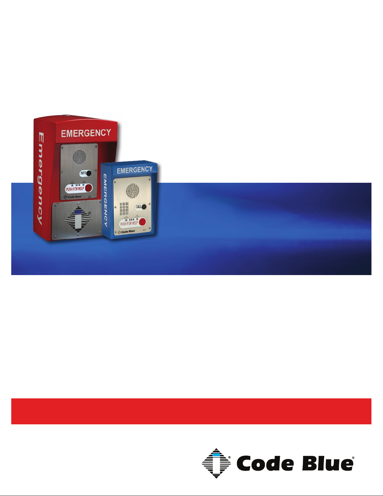
CB 4 Series
Installation, Configuration, Operation & Troubleshooting
CB 4-s
CB 4-r
CB 4-d
CB 4-u
Administrator Guide
800.205.7186 • www.codeblue.com
Page 2

CB 4 Series
Administrator Guide
WARNING
ONLY QUALIFIED PERSONNEL SHOULD INSTALL THESE UNITS. THE INSTALLATION
SHOULD CONFORM TO ALL LOCAL CODES. IN SOME COUNTRIES, A CERTIFIED ELECTRICIAN MAY BE REQUIRED.
NOTICE TO USERS
Copyright © Code Blue Corporation. All rights reserved. This guide or software described herein, in
whole or part, shall not be reproduced, translated or reduced to any machine-readable form without
prior written approval from Code Blue Corporation.
CODE BLUE CORPORATION PROVIDES NO WARRANTY WITH REGARD TO THIS GUIDE, THE
SOFTWARE OR OTHER INFORMATION CONTAINED HEREIN AND HEREBY EXPRESSLY DISCLAIMS ANY IMPLIED WARRANTIES OF MERCHANTABILITY OR FITNESS FOR ANY PARTICULAR PURPOSE WITH REGARD TO THIS GUIDE, THE SOFTWARE OR SUCH OTHER INFORMATION. IN NO EVENT SHALL CODE BLUE CORPORATION BE LIABLE FOR ANY INCIDENTAL,
CONSEQUENTIAL, OR SPECIAL DAMAGES, WHETHER BASED ON TORT, CONTRACT, OR
OTHERWISE, ARISING OUT OF OR IN CONNECTIONS WITH THIS GUIDE, THE SOFTWARE
OR OTHER INFORMATION CONTAINED HEREIN OR THE USE THEREOF.
Code Blue Corporation reserves the right to make any modications to this guide or the information
contained herein at any time without notice. The software described herein may also be governed
by the terms of a separate user license agreement.
Code Blue® is a registered trademark of Code Blue Corporation.
Code Blue • 259 Hedcor Street • Holland, MI 49423 USA • 800.205.7186 • www.codeblue.com
GU-160-Cpage 2 of 45
Page 3

CB 4 Series
Administrator Guide
Table of Contents
Section Page
2 Introduction.................................................................................... 4
3 Getting Started............................................................................... 6
4 Spare Parts..................................................................................... 8
5 Power Requirements...................................................................... 10
6 Software Conguration.................................................................. 12
7 CB 4-s Low Voltage Exploded View.............................................. 13
8 CB 4-r Low Voltage Exploded View.............................................. 14
9 CB 4d Low Voltage Exploded View.............................................. 15
10 CB 4-u Low Voltage Exploded View............................................. 16
11 CB 4-u High Voltage Exploded View............................................. 17
12 CB 4-s Installation Instructions.................................................... 18
13 CB 4-d Installation Instructions.................................................... 20
14 CB 4-r Installation Instructions..................................................... 22
15 CB 4-u Installation Instructions.................................................... 24
16 CB 4 Series Remote Mount Beacon/Strobe Installation............. 27
17 S-1000/S-1050 Installation Instructions........................................ 28
18 PoE Installation Instructions......................................................... 30
19 CB 4 Series Pole Mount Installation Instructions........................ 31
20 CB 4-u Solar Installation Instructions........................................... 32
21 CB 4 Series Standard Wiring......................................................... 33
22 WM-180 Wall Mount Installation Instructions.............................. 34
23 WM-180 Pole Mount Installation Instructions.............................. 37
24 GSM Wireless Wiring Diagram (CB 4-u only)............................... 38
25 Solar and WindAssist Wiring Diagram (CB 4-u only).................. 39
26 NightCharge® Wiring Diagram (CB 4-u only)................................ 40
27 Maintenance Schedule................................................................... 41
28 Locating Unit Serial Numbers........................................................ 43
29 Warranty........................................................................................... 44
30 Download Information.................................................................... 45
Code Blue • 259 Hedcor Street • Holland, MI 49423 USA • 800.205.7186 • www.codeblue.com
GU-160-Cpage 3 of 45
Page 4

CB 4 Series
Administrator Guide
2 Introduction
The 4 Series Wall Mount Enclosures
Thank you for choosing the CB 4 Series for your Code Blue application.
The CB 4 Series is our basic communication unit designed for wall or pole installations in interior
and exterior applications. The all-steel housing and Code Blue’s speakerphone system meet the
need for a highly vandal resistant unit, while providing a cost-effective and reliable solution.
The CB 4 Series is a good choice for dorm and building entrances, hallways and transit centers.
The exclusive analog InterAct and VoIP speakerphones are designed for maximum reliability, vandal
resistance, auxiliary functions, mass notication control, and fault monitoring and reporting capabilities. (see IA4100 or IP5000 guides for more information on our speakerphones)
Our unmistakable craftsmanship makes our enclosures the most rugged on the market, withstanding the punishment of natural and man-made disasters. CB 4 Series units have a rugged steel
construction, industrial engineering grade reective graphics and weather, UV and grafti resistant
paint.
Other options include:
• IP and analog phones
• Low power consumption LED faceplate light
• 180° Public Address Speaker (PAS)
• Remote Mount Beacon/Strobe
• GSM – CB 4-u Only
• NightCharge® – CB 4-u only
• Solar – CB 4-u only
• Directory Plate
• Color IP Camera – CB 4-d only
• Custom Cut-out Stainless Steel Plate – CB 4-u only
Code Blue • 259 Hedcor Street • Holland, MI 49423 USA • 800.205.7186 • www.codeblue.com
GU-160-Cpage 4 of 45
Page 5
CB 4 Series
Administrator Guide
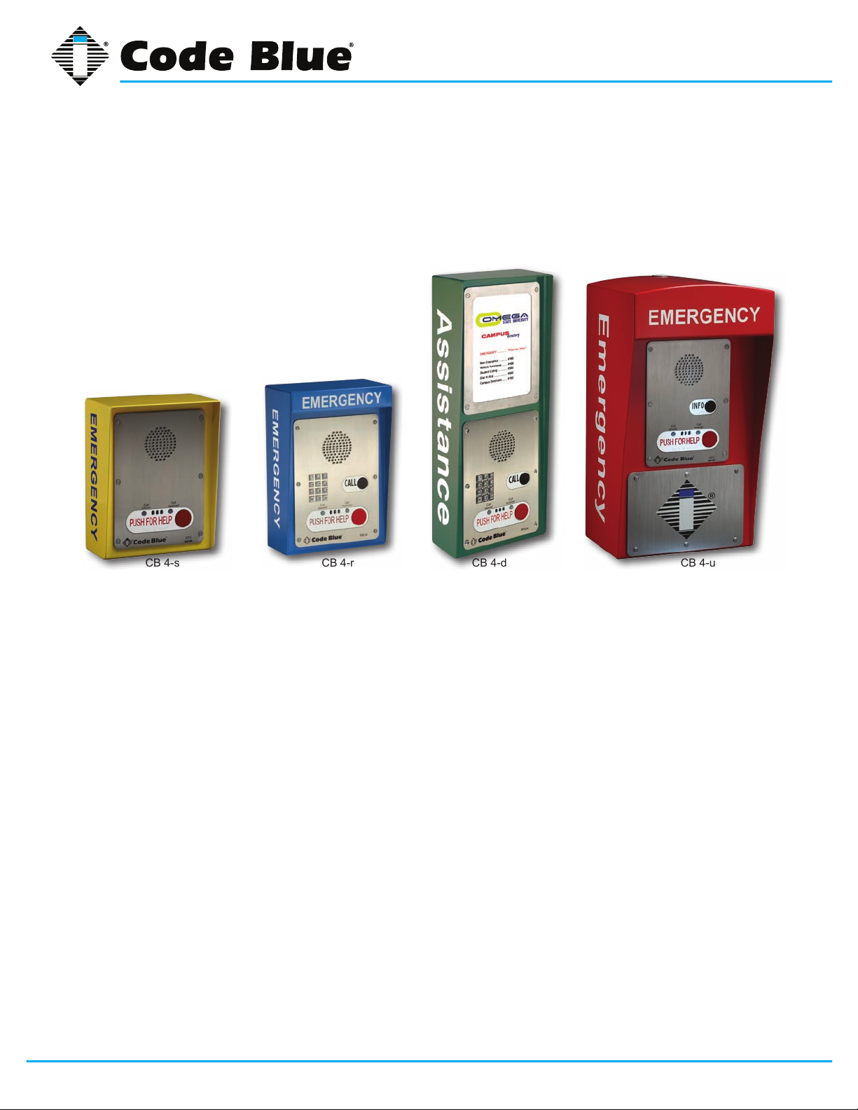
This guide contains all of the Code Blue CB 4 Series information for the CB 4-s, CB 4-u, CB 4-d and
CB 4-r. This guide contains a general overview of the CB 4 Series options and its application, installation and wiring.
CB 4-uCB 4-dCB 4-s CB 4-r
Code Blue • 259 Hedcor Street • Holland, MI 49423 USA • 800.205.7186 • www.codeblue.com
GU-160-Cpage 5 of 45
Page 6
CB 4 Series
Administrator Guide
3 Getting Started
Basic Install Instructions
1. EIA/TIA, ANSI, CSA and BICSI cabling or similar standards shall be adhered to for proper
operation of Code Blue communication devices connected to copper or ber infrastructures.
Communications cable and electrical cable in the same conduit is not an acceptable instal lation and shall not be supported. Analog phones require a minimum of 23mA for proper
operation (26-29mA recommended).
2. Each analog speakerphone requires its own phone line or PBX extension. Multiple units
shall not be supported.
3. Speakerphones require programming before operation. Consult the User Guide or Admin istrator Guide enclosed with the unit or go to www.codeblue.com > Support > Downloads to
read or download manuals.
4. If you are installing IP speakerphones, please read the appropriate manuals and consult
with your Network Administrator.
5. Size electrical wiring based on length of run.
6. Consult the enclosed document packet for internal wiring instructions.
What’s Included
Quantity Part Description
1 Wall Anchor Kit - 4-3/8 Bolts, 4-Washers, 4-Rubber Washers 4-Cement Anchors
1 Security Bit
1 Enclosure - CB 4-s, CB 4-r, CB 4-d or CB 4-u
1 Access Plate – CB 4-u Only
1 URL listing sheet of Installation, Programming, Wiring & Warranty locations
1 Blank Stainless Steel Plate - CB 4-d only
1 55-amp Battery – CB 4-u Solar only
1 Solar Panel Assembly – CB 4-u only
Code Blue • 259 Hedcor Street • Holland, MI 49423 USA • 800.205.7186 • www.codeblue.com
GU-160-Cpage 6 of 45
Page 7

CB 4 Series
Administrator Guide
Tools Required
CB 4-s, CB 4-r and CB 4-d
1. Ladder to reach above unit – For Remote Beacon/Strobe Only
2. Drill and security bit for removing and inserting security screws on phone
3. 3/8 socket set to mount unit onto wall
CB 4-u
1. Ladder to reach above unit – CB4-u Solar or Remote Mount Beacon/Strobe Kit
2. Drill and security bit for removing and inserting security screws on phone and access plate
3. t
4. 3/8 socket set to mount unit onto wall
5. Banding Tool for Pole Mount Kit
Code Blue • 259 Hedcor Street • Holland, MI 49423 USA • 800.205.7186 • www.codeblue.com
GU-160-Cpage 7 of 45
Page 8
4 Spare Parts
CB 4-s
Part Part Number
Faceplate Screws 41544 (6pk)
Manifold R/B 5-way 40101
Analog Surge Suppressor 41471
IP Surge Suppressor 41421
CB 4-d
Part Part Number
Faceplate Screws 41544 (6pk)
Manifold R/B 5-way 40101
Analog Surge Suppressor 41471
IP Surge Suppressor 41421
Blank Stainless Steel Plate Assembly 40066
CB 4 Series
Administrator Guide
CB 4-r
Part Part Number
LED Faceplate Light 40196
Faceplate Screws 41544 (6pk)
Analog Surge Suppressor 41471
IP Surge Suppressor 41421
Manifold R/B 5-way 40101
CB 4-u
Part Part Number
LED Faceplate Light 40196
Faceplate Screws 41544 (6pk)
Access Plate Screws 41500 x 2
Manifold R/B 5-way 40101
Analog Surge Suppressor 41471
IP Surge Suppressor 41421
Code Blue • 259 Hedcor Street • Holland, MI 49423 USA • 800.205.7186 • www.codeblue.com
GU-160-Cpage 8 of 45
Page 9
Administrator Guide
CB 4 Series Additional Options
Part Part Number
Solar Battery – CB 4-u only 41537
Solar Panel – CB 4-u only 40156
GSM Assembly – CB 4-u only - Solar only 40028
GSM Assembly – CB 4-u only – NightCharge
Service Plate - Lexan w/graphics (This Location Being Serviced) 40208
Pole Mount Kit 40027
Triad Transformer 40VA 120V (will not power accessories) – CB 4-u only 41246
Remote Mount Beacon/Strobe Kit 40525
POE Power Splitter Kit Assembly 41574
IP5000 Speakerphone FP1 50101
IP5000 Speakerphone FP2 50102
IP5000 Speakerphone FP3 50103
Directory Plate Assembly – CB 4-d only 40057
Color Camera Assembly – CB 4-d only 41420
Wind Operated Generator – CB 4-u only 40355
Remote Mount Beacon Kit (Photocell) 40528
Multi-tap Power Brick – CB 4-u only 40104
Curb Mount Stand – (Excludes the CB 4-u) 41432
®
only 40026
CB 4 Series
Code Blue • 259 Hedcor Street • Holland, MI 49423 USA • 800.205.7186 • www.codeblue.com
GU-160-Cpage 9 of 45
Page 10
CB 4 Series
Administrator Guide
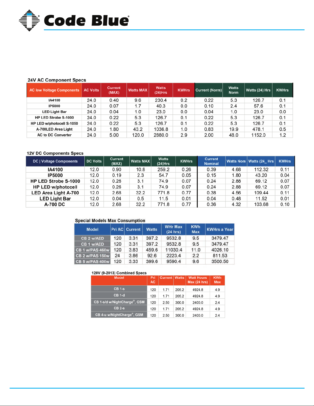
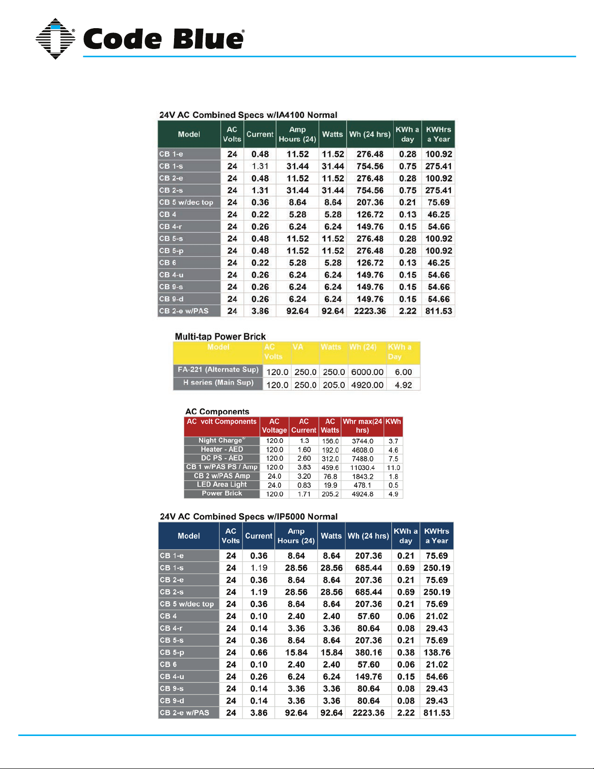
5 Power Requirements
(The following power requirements include the 4 Series and also ALL OTHER Code Blue units.)
Code Blue • 259 Hedcor Street • Holland, MI 49423 USA • 800.205.7186 • www.codeblue.com
GU-160-Cpage 10 of 45
Page 11
CB 4 Series
Administrator Guide
Code Blue • 259 Hedcor Street • Holland, MI 49423 USA • 800.205.7186 • www.codeblue.com
GU-160-Cpage 11 of 45
Page 12

CB 4 Series
Administrator Guide
6 Software Configuration
Blue Alert® MNS Software
Blue Alert MNS (Mass Notication Software) lls a need in the marketplace for an incident response
solution that is both comprehensive and cost-effective, while also providing an efcient way to detect
and respond. The advanced mass notication system allows responders to deliver multi-layered
emergency notications via a wide range of platforms, including email, text message (SMS), emer-
gency phones, public address speakers, social media, desktop alerts and more, quickly informing
and directing people in emergency situations.
Blue Alert® EMS
Blue Alert EMS is an advanced software solution that handles all incoming events effectively by remotely controlling emergency communication devices with an easy-to-use Graphical User Interface
(GUI). You also will have the ability to open gates and AED access doors, turn LED beacon/strobes
on or off, transfer calls to Public Address Systems to make area wide announcements and incorporate other ancillary devices and applications while the system securely archives data for future
reference.
ToolVox®
A sophisticated emergency management platform for your blue light phone network, ToolVox offers
unique real-time monitoring and provisioning options for emergency phones and public address
speakers, effectively acting as a hub for connecting Help Points® and other Code Blue devices. Using our proprietary incident response software, Blue Alert® MNS and EMS, you can send alerts via
outdoor platforms, such as blue light phones and public address speakers. It also provides connections to PBX, public telephone (PSTN) and Internet (ISP) networks, in addition to third party security
platforms.
Code Blue • 259 Hedcor Street • Holland, MI 49423 USA • 800.205.7186 • www.codeblue.com
GU-160-Cpage 12 of 45
Page 13
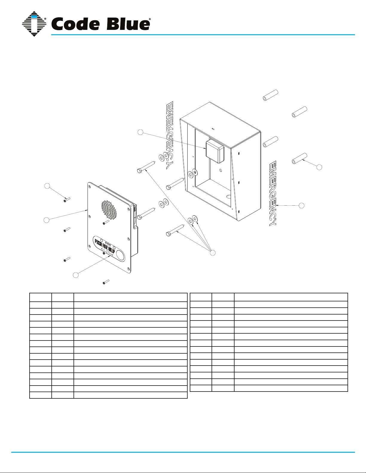
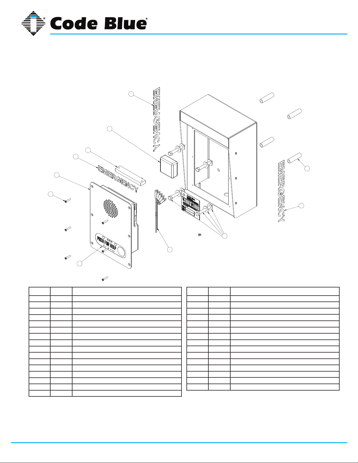
7 CB 4-s Low Voltage Exploded View
3
5
CB 4 Series
Administrator Guide
2
4
6
BALL # PART # DESCRIPTION
1 CALL Standard / Custom Graphic
2 40102 Wall Anchor Kit
3 41471 Analog Surge Suppressor
3 41421 IP Surge Suppressor
4 50001 Single Button IA4100 Analog Phone – PUSH FOR HELP
4 50002 Double Button IA4100 Analog Phone – PUSH FOR HELP
4 50003 Keypad IA4100 Analog Phone – PUSH FOR HELP
4 50004 Single Button IA4100 Analog Phone – EMERGENCY
4 50005 Double Button IA4100 Analog Phone – EMERGENCY
4 50006 Keypad IA4100 Analog Phone – EMERGENCY
4 50007 Single Button IA4100 Analog Phone – EMERGENCY/EMERGENCIA
4 50008 Double Button IA4100 Analog Phone – EMERGENCY/EMERGENCIA
4 50009 Keypad IA4100 Analog Phone – EMERGENCY/EMERGENCIA
4 50101 Single Button IP5000 Phone – PUSH FOR HELP
4 50102 Double Button IP5000 Phone – PUSH FOR HELP
1
2
BALL # PART # DESCRIPTION
4 50103 Keypad IP5000 Phone – PUSH FOR HELP
4 50104 Single Button IP5000 Phone – EMERGENCY
4 50105 Double Button IP5000 Phone – EMERGENCY
4 50106 Keypad IP5000 Phone – EMERGENCY
4 50107 Single Button IP5000 Phone – EMERGENCY/EMERGENCIA
4 50108 Double Button IP5000 Phone – EMERGENCY/EMERGENCIA
4 50109 Keypad IP5000 Phone – EMERGENCY/EMERGENCIA
5 41544 Faceplate Security Screw 10x24 (6 pk)
6 40357 Bezel Assembly IA4100 Analog Phone – PUSH FOR HELP
6 40407 Bezel Assembly IA4100 Analog Phone – EMERGENCY
6 40408 Bezel Assembly IA4100 Analog Phone – EMERGENCY/EMERGENCIA
6 40313 Bezel Assembly IP5000 Analog Phone – PUSH FOR HELP
6 40405 Bezel Assembly IP5000 Analog Phone – EMERGENCY
6 40406 Bezel Assembly IP5000 Analog Phone – EMERGENCY/EMERGENCIA
DISCLAIMER: Product design and component use subject to change without notice. Product shown reasonably represents current offering and
is intended to assist in component identication. Reference the model and serial number from the unit ID tag and contact manufacturer to conrm
replacement part version and availability.
Code Blue • 259 Hedcor Street • Holland, MI 49423 USA • 800.205.7186 • www.codeblue.com
GU-160-Cpage 13 of 45
Page 14
8 CB 4-r Low Voltage Exploded View
1
3
7
1
4
5
CB 4 Series
Administrator Guide
2
8
BALL # PART # DESCRIPTION
1 CALL Standard / Custom Graphic
2 40102 Wall Anchor Kit
3 41471 Analog Surge Suppressor
3 41421 IP Surge Suppressor
4 50001 Single Button IA4100 Analog Phone – PUSH FOR HELP
4 50002 Double Button IA4100 Analog Phone – PUSH FOR HELP
4 50003 Keypad IA4100 Analog Phone – PUSH FOR HELP
4 50004 Single Button IA4100 Analog Phone – EMERGENCY
4 50005 Double Button IA4100 Analog Phone – EMERGENCY
4 50006 Keypad IA4100 Analog Phone – EMERGENCY
4 50007 Single Button IA4100 Analog Phone – EMERGENCY/EMERGENCIA
4 50008 Double Button IA4100 Analog Phone – EMERGENCY/EMERGENCIA
4 50009 Keypad IA4100 Analog Phone – EMERGENCY/EMERGENCIA
4 50101 Single Button IP5000 Phone – PUSH FOR HELP
4 50102 Double Button IP5000 Phone – PUSH FOR HELP
4 50103 Keypad IP5000 Phone – PUSH FOR HELP
1
2
6
BALL # PART # DESCRIPTION
4 50104 Single Button IP5000 Phone – EMERGENCY
4 50105 Double Button IP5000 Phone – EMERGENCY
4 50106 Keypad IP5000 Phone – EMERGENCY
4 50107 Single Button IP5000 Phone – EMERGENCY/EMERGENCIA
4 50108 Double Button IP5000 Phone – EMERGENCY/EMERGENCIA
4 50109 Keypad IP5000 Phone – EMERGENCY/EMERGENCIA
5 41544 Faceplate Security Screw 10x24 (6 pk)
6 40101 Manifold R/B 5-way
7 41548 LED Faceplate Light
8 40357 Bezel Assembly IA4100 Analog Phone – PUSH FOR HELP
8 40407 Bezel Assembly IA4100 Analog Phone – EMERGENCY
8 40408 Bezel Assembly IA4100 Analog Phone – EMERGENCY/EMERGENCIA
8 40313 Bezel Assembly IP5000 Analog Phone – PUSH FOR HELP
8 40405 Bezel Assembly IP5000 Analog Phone – EMERGENCY
8 40406 Bezel Assembly IP5000 Analog Phone – EMERGENCY/EMERGENCIA
DISCLAIMER: Product design and component use subject to change without notice. Product shown reasonably represents current offering and
is intended to assist in component identication. Reference the model and serial number from the unit ID tag and contact manufacturer to conrm
replacement part version and availability.
Code Blue • 259 Hedcor Street • Holland, MI 49423 USA • 800.205.7186 • www.codeblue.com
GU-160-Cpage 14 of 45
Page 15

9 CB 4-d Low Voltage Exploded View
3
CB 4 Series
Administrator Guide
8
5
4
7
BALL # PART # DESCRIPTION
1 CALL Standard / Custom Graphic
2 40102 Wall Anchor Kit
3 41471 Analog Surge Suppressor
3 41421 IP Surge Suppressor
4 50001 Single Button IA4100 Analog Phone – PUSH FOR HELP
4 50002 Double Button IA4100 Analog Phone – PUSH FOR HELP
4 50003 Keypad IA4100 Analog Phone – PUSH FOR HELP
4 50004 Single Button IA4100 Analog Phone – EMERGENCY
4 50005 Double Button IA4100 Analog Phone – EMERGENCY
4 50006 Keypad IA4100 Analog Phone – EMERGENCY
4 50007 Single Button IA4100 Analog Phone – EMERGENCY/EMERGENCIA
4 50008 Double Button IA4100 Analog Phone – EMERGENCY/EMERGENCIA
4 50009 Keypad IA4100 Analog Phone – EMERGENCY/EMERGENCIA
4 50101 Single Button IP5000 Phone – PUSH FOR HELP
4 50102 Double Button IP5000 Phone – PUSH FOR HELP
4 50103 Keypad IP5000 Phone – PUSH FOR HELP
4 50104 Single Button IP5000 Phone – EMERGENCY
4 50105 Double Button IP5000 Phone – EMERGENCY
2
1
6
BALL # PART # DESCRIPTION
4 50106 Keypad IP5000 Phone – EMERGENCY
4 50107 Single Button IP5000 Phone – EMERGENCY/EMERGENCIA
4 50108 Double Button IP5000 Phone – EMERGENCY/EMERGENCIA
4 50109 Keypad IP5000 Phone – EMERGENCY/EMERGENCIA
5 41544 Faceplate Security Screw 10x24 (6 pk)
6 40101 Manifold R/B 5-way
7 40357 Bezel Assembly IA4100 Analog Phone – PUSH FOR HELP
7 40407 Bezel Assembly IA4100 Analog Phone – EMERGENCY
7 40408 Bezel Assembly IA4100 Analog Phone – EMERGENCY/EMERGENCIA
7 40313 Bezel Assembly IP5000 Analog Phone – PUSH FOR HELP
7 40405 Bezel Assembly IP5000 Analog Phone – EMERGENCY
7 40406 Bezel Assembly IP5000 Analog Phone – EMERGENCY/EMERGENCIA
8 40066 Blank Plate Assembly
8 40067 Directory Assembly
8 40130 Color Camera Assembly
8 40131 Card Reader Assembly
8 40157 Color Camera and Card Reader Assembly
DISCLAIMER: Product design and component use subject to change without notice. Product shown reasonably represents current offering and
is intended to assist in component identication. Reference the model and serial number from the unit ID tag and contact manufacturer to conrm
replacement part version and availability.
Code Blue • 259 Hedcor Street • Holland, MI 49423 USA • 800.205.7186 • www.codeblue.com
GU-160-Cpage 15 of 45
Page 16

10 CB 4-u Low Voltage Exploded View
3
CB 4 Series
Administrator Guide
3
4
1
6
7
9
8
BALL # PART # DESCRIPTION
1 CALL Standard / Custom Graphic
2 41471 Analog Surge Suppressor
2 41421 IP Surge Suppressor
3 40102 Wall Anchor Kit
4 41548 LED Faceplate Light
5 40101 Manifold R/B 5-way
6 41544 Faceplate Security Screw 10x24 (6 pk)
7 50001 Single Button IA4100 Analog Phone – PUSH FOR HELP
7 50002 Double Button IA4100 Analog Phone – PUSH FOR HELP
7 50003 Keypad IA4100 Analog Phone – PUSH FOR HELP
7 50004 Single Button IA4100 Analog Phone – EMERGENCY
7 50005 Double Button IA4100 Analog Phone – EMERGENCY
7 50006 Keypad IA4100 Analog Phone – EMERGENCY
7 50007 Single Button IA4100 Analog Phone – EMERGENCY/EMERGENCIA
7 50008 Double Button IA4100 Analog Phone – EMERGENCY/EMERGENCIA
7 50009 Keypad IA4100 Analog Phone – EMERGENCY/EMERGENCIA
2
1
5
BALL # PART # DESCRIPTION
7 50101 Single Button IP5000 Phone – PUSH FOR HELP
7 50102 Double Button IP5000 Phone – PUSH FOR HELP
7 50103 Keypad IP5000 Phone – PUSH FOR HELP
7 50104 Single Button IP5000 Phone – EMERGENCY
7 50105 Double Button IP5000 Phone – EMERGENCY
7 50106 Keypad IP5000 Phone – EMERGENCY
7 50107 Single Button IP5000 Phone – EMERGENCY/EMERGENCIA
7 50108 Double Button IP5000 Phone – EMERGENCY/EMERGENCIA
7 50109 Keypad IP5000 Phone – EMERGENCY/EMERGENCIA
8 41418 Button Head Security Screws (3 pk)
9 40357 Bezel Assembly IA4100 Analog Phone – PUSH FOR HELP
9 40407 Bezel Assembly IA4100 Analog Phone – EMERGENCY
9 40408 Bezel Assembly IA4100 Analog Phone – EMERGENCY/EMERGENCIA
9 40313 Bezel Assembly IP5000 Analog Phone – PUSH FOR HELP
9 40405 Bezel Assembly IP5000 Analog Phone – EMERGENCY
9 40406 Bezel Assembly IP5000 Analog Phone – EMERGENCY/EMERGENCIA
DISCLAIMER: Product design and component use subject to change without notice. Product shown reasonably represents current offering and
is intended to assist in component identication. Reference the model and serial number from the unit ID tag and contact manufacturer to conrm
replacement part version and availability.
Code Blue • 259 Hedcor Street • Holland, MI 49423 USA • 800.205.7186 • www.codeblue.com
GU-160-Cpage 16 of 45
Page 17

11 CB 4-u High Voltage Exploded View
4
1
6
CB 4 Series
Administrator Guide
3
5
7
9
BALL # PART # DESCRIPTION
1 CALL Standard / Custom Graphic
2 41471 Analog Surge Suppressor
2 41421 IP Surge Suppressor
3 40102 Wall Anchor Kit
4 41548 LED Faceplate Light
5 40104 Power Brick 120V, 240V, 277V, 347V
6 41544 Faceplate Security Screw 10x24 (6 pk)
7 50001 Single Button IA4100 Analog Phone – PUSH FOR HELP
7 50002 Double Button IA4100 Analog Phone – PUSH FOR HELP
7 50003 Keypad IA4100 Analog Phone – PUSH FOR HELP
7 50004 Single Button IA4100 Analog Phone – EMERGENCY
7 50005 Double Button IA4100 Analog Phone – EMERGENCY
7 50006 Keypad IA4100 Analog Phone – EMERGENCY
7 50007 Single Button IA4100 Analog Phone – EMERGENCY/EMERGENCIA
7 50008 Double Button IA4100 Analog Phone – EMERGENCY/EMERGENCIA
7 50009 Keypad IA4100 Analog Phone – EMERGENCY/EMERGENCIA
1
8
2
BALL # PART # DESCRIPTION
7 50101 Single Button IP5000 Phone – PUSH FOR HELP
7 50102 Double Button IP5000 Phone – PUSH FOR HELP
7 50103 Keypad IP5000 Phone – PUSH FOR HELP
7 50104 Single Button IP5000 Phone – EMERGENCY
7 50105 Double Button IP5000 Phone – EMERGENCY
7 50106 Keypad IP5000 Phone – EMERGENCY
7 50107 Single Button IP5000 Phone – EMERGENCY/EMERGENCIA
7 50108 Double Button IP5000 Phone – EMERGENCY/EMERGENCIA
7 50109 Keypad IP5000 Phone – EMERGENCY/EMERGENCIA
8 41418 Button Head Security Screws (3 pk)
9 40357 Bezel Assembly IA4100 Analog Phone – PUSH FOR HELP
9 40407 Bezel Assembly IA4100 Analog Phone – EMERGENCY
9 40408 Bezel Assembly IA4100 Analog Phone – EMERGENCY/EMERGENCIA
9 40313 Bezel Assembly IP5000 Analog Phone – PUSH FOR HELP
9 40405 Bezel Assembly IP5000 Analog Phone – EMERGENCY
9 40406 Bezel Assembly IP5000 Analog Phone – EMERGENCY/EMERGENCIA
DISCLAIMER: Product design and component use subject to change without notice. Product shown reasonably represents current offering and
is intended to assist in component identication. Reference the model and serial number from the unit ID tag and contact manufacturer to conrm
replacement part version and availability.
Code Blue • 259 Hedcor Street • Holland, MI 49423 USA • 800.205.7186 • www.codeblue.com
GU-160-Cpage 17 of 45
Page 18

CB 4 Series
Administrator Guide
12 CB 4-s Installation Instructions
1.0 PRE-INSTALLATION
1.1 Electrical preparation – The unit may have supply wires run from either A) behind the unit
through the wall, or B) below the unit using an external conduit through the bottom of the
unit’s back plate. Holes in the back and bottom of the unit have been provided for this purpose.
2.0 INSTALLATION PROCEDURES
2.1 Mark the mounting holes – In order to comply with the Americans with Disabilities Act
(ADA) of 1990, the speakerphone button(s) should be positioned between 34 and 48 inches
from grade level. (Consult an ADA specialist in your area to verify local and federal guidelines.)
2.2 Drill all marked holes.
2.3 Secure the housing to the wall – Four anchors of appropriate size and type should be
used to securely fasten the housing to the wall or pole mount.
IMPORTANT: If wiring is coming in from the back, ensure that the conduit is aligned at this
time.
2.4 Connect electrical and communications wiring. Follow all federal and local codes that apply.
Code Blue • 259 Hedcor Street • Holland, MI 49423 USA • 800.205.7186 • www.codeblue.com
GU-160-Cpage 18 of 45
Page 19

1 3/16
MOUNTING SURFACE
CB 4 Series
Administrator Guide
4 9/16 REF
BOTTOM PLATE
13 5/16 REF
BOTTOM
(KNOCKOUT FOR
Ø7/8
Ø1/2 CONDUIT)
Ø7/8 THRU BOTTOM PLATE
(KNOCKOUT FOR Ø1/2 CONDUIT)
5 1/8 REF
2 7/8
10 1/4 REF
4 X Ø7/16 MOUNTING HOLES
4 1/16
8
2 1/2 REF
2 1/4 REF
2 7/8
5 3/4
GROUND/FLOOR
Suggested installation dimensions shown from ground to lower right mounting hole are for single button faceplates.
• For dual button faceplate, deduct 3.25 inches.
• For keypad faceplate, deduct 4.5 inches.
• For wheelchair direct facing access only, deduct 6 inches.
DISCLAIMER: The dimensions above are intended as guidelines only. For specic installation requirements,
reference your local codes.
All wiring must be installed and connected by experienced and certied personnel to meet
local and national electrical codes, and will include a service disconnect.
Code Blue • 259 Hedcor Street • Holland, MI 49423 USA • 800.205.7186 • www.codeblue.com
41-5/8
GU-160-Cpage 19 of 45
Page 20

CB 4 Series
Administrator Guide
13 CB 4-d Installation Instructions
1.0 PRE-INSTALLATION
1.1 Electrical preparation – The unit may have supply wires run from either A) behind the unit
through the wall, or B) below the unit using an external conduit through the bottom of the
unit’s back plate. Holes in the back and bottom of the unit have been provided for this purpose.
2.0 INSTALLATION PROCEDURES
2.1 Mark the mounting holes – In order to comply with the Americans with Disabilities Act
(ADA) of 1990, the speakerphone button(s) should be positioned between 34 and 48 inches
from grade level. (Consult an ADA specialist in your area to verify local and federal guidelines.)
2.2 Drill all marked holes.
2.3 Secure the housing to the wall – Four anchors of appropriate size and type should be
used to securely fasten the housing to the wall or pole mount.
IMPORTANT: If wiring is coming in from the back, ensure that the conduit is aligned at this
time.
2.4 Connect electrical and communications wiring. Follow all federal and local codes that
apply.
Code Blue • 259 Hedcor Street • Holland, MI 49423 USA • 800.205.7186 • www.codeblue.com
See diagrams next page
GU-160-Cpage 20 of 45
Page 21

1 3/16
MOUNTING SURFACE
CB 4 Series
Administrator Guide
25 3/4 REF
4 9/16 REF
BOTTOM PLATE
(KNOCKOUT FOR
Ø1/2 CONDUIT)
Ø7/8 THRU BOTTOM PLATE
(KNOCKOUT FOR Ø1/2 CONDUIT)
5 1/8 REF
2 7/8
4 X Ø7/16 MOUNTING HOLES
Ø7/8
4 1/16
8
8 3/4 REF
BOTTOM
2 1/4 REF
5 3/4
10 1/4 REF
47-7/8
GROUND/FLOOR
Suggested installation dimensions shown from ground to lower right mounting hole are for single button faceplates.
• For dual button faceplate, deduct 3.25 inches.
• For keypad faceplate, deduct 4.5 inches.
• For wheelchair direct facing access only, deduct 6 inches.
DISCLAIMER: The dimensions above are intended as guidelines only. For specic installation requirements,
reference your local codes.
All wiring must be installed and connected by experienced and certied personnel to meet
local and national electrical codes, and will include a service disconnect.
Code Blue • 259 Hedcor Street • Holland, MI 49423 USA • 800.205.7186 • www.codeblue.com
GU-160-Cpage 21 of 45
Page 22

CB 4 Series
Administrator Guide
14 CB 4-r Installation Instructions
1.0 PRE-INSTALLATION
1.1 Electrical preparation – The unit may have supply wires run from either A) behind the unit
through the wall, or B) below the unit using an external conduit through the bottom of the unit.
Holes in the back and bottom of the unit have been provided for this purpose.
2.0 INSTALLATION PROCEDURES
2.1 Mark the mounting holes – In order to comply with the Americans with Disabilities Act (ADA)
of 1990, the speakerphone button(s) should be positioned between 34 and 48 inches from
grade level (Consult an ADA specialist in your area to verify local and federal guidelines).
2.2 Drill all marked holes.
2.3 Secure the housing to the wall – Four anchors of appropriate size and type should be used
to securely fasten the housing to the wall or pole mount.
IMPORTANT: If wiring is coming in from the back, ensure that the conduit is aligned at this time.
2.4 Connect electrical and communications wiring. Follow all federal and local codes that apply.
15-1/4
G
6
10-1/4
R
A
P
H
I
C
5-3/4
8
2-3/4
4-1/16
Code Blue • 259 Hedcor Street • Holland, MI 49423 USA • 800.205.7186 • www.codeblue.com
See diagrams next page
GU-160-Cpage 22 of 45
Page 23

1 3/16
MOUNTING SURFACE
CB 4 Series
Administrator Guide
4 9/16 REF
BOTTOM PLATE
15 1/4 REF
BOTTOM
(KNOCKOUT FOR
Ø7/8
Ø1/2 CONDUIT)
Ø7/8 THRU BOTTOM PLATE
(KNOCKOUT FOR Ø1/2 CONDUIT)
5 1/8 REF
2 7/8
10 1/4 REF
4 X Ø7/16 MOUNTING HOLES
4 1/16
8
2 3/4 REF
2 1/4 REF
2 7/8
5 3/4
GROUND/FLOOR
Suggested installation dimensions shown from ground to lower right mounting hole are for single button faceplates.
• For dual button faceplate, deduct 3.25 inches.
• For keypad faceplate, deduct 4.5 inches.
• For wheelchair direct facing access only, deduct 6 inches.
DISCLAIMER: The dimensions above are intended as guidelines only. For specic installation requirements,
reference your local codes.
All wiring must be installed and connected by experienced and certied personnel to meet
local and national electrical codes, and will include a service disconnect.
Code Blue • 259 Hedcor Street • Holland, MI 49423 USA • 800.205.7186 • www.codeblue.com
41-5/8
GU-160-Cpage 23 of 45
Page 24

15 CB 4-u Installation Instructions
1.0 PRE-INSTALLATION
1.1 Electrical preparation – The unit may have supply wires run from either (a) behind the
unit through the wall, or (b) below the unit using an external conduit through the bottom of
the unit’s back plate. Holes in the bottom of the unit have been provided for this purpose.
Holes in the back of the unit must be provided by others.
2.0 INSTALLATION PROCEDURES
2.1 Mark the mounting holes – In order to comply with the Americans with Disabilities Act
(ADA) of 1990, the speakerphone button(s) should be positioned between 34 and 48
inches from grade level. (Consult an ADA specialist in your area to verify local and federal
guidelines.)
2.2 Drill all marked holes.
CB 4 Series
Administrator Guide
2.3 Secure the housing to the wall – Four anchors of appropriate size and type should be
used to securely fasten the housing to the wall or pole mount.
IMPORTANT: If wiring is being supplied from the back, ensure that the conduit is aligned
at this time.
2.4 Connect electrical and communications wiring (see wiring instructions). Follow all national
and local codes that apply.
3.0 WIRING (Excludes NightCharge® or solar options)
3.1 Ground – The ground (green) wire should be stripped and fastened to the supplied grounding lug.
3.2 24V AC supply – Using the proper crimping tool, attach a #8 fork to each of the incoming
power wires and fasten them to the terminal screws labeled “Line” and “Neutral.”
3.3 120/240V AC supply – Using the proper crimping tool, attach a #8 fork to each of the incoming power wires and fasten them to the correct terminals as labeled on the transformer.
After completing the wire connections, install the supplied terminal covers.
See diagrams next page
Code Blue • 259 Hedcor Street • Holland, MI 49423 USA • 800.205.7186 • www.codeblue.com
GU-160-Cpage 24 of 45
Page 25

CB 4 Series
Administrator Guide
Code Blue • 259 Hedcor Street • Holland, MI 49423 USA • 800.205.7186 • www.codeblue.com
GU-160-Cpage 25 of 45
Page 26

8 7/8 REF
BOTTOM PLATE
14 REF
1 5/8 REF
MOUNTING SURFACE
1 5/8
CB 4 Series
Administrator Guide
Ø1-1/8 THRU BOTTOM PLATE
(KNOCKOUT FOR 3/4 CONDUIT)
Ø1-1/8 THRU TOP PLATE
(KNOCKOUT FOR Ø3/4 CONDUIT)
25 3/4 REF
BOTTOM
2 7/8
5 3/4
2 1/2
4 X Ø9/16 MOUNTING HOLES
8
9 1/8 REF
4 1/8 REF
40-1/4
GROUND/FLOOR
Suggested installation dimensions shown from ground to lower right mounting hole are for single button faceplates.
• For dual button faceplate, deduct 3.25 inches.
• For keypad faceplate, deduct 4.5 inches.
• For wheelchair direct facing access only, deduct 6 inches.
DISCLAIMER: The dimensions above are intended as guidelines only. For specic installation requirements,
reference your local codes.
All wiring must be installed and connected by experienced and certied personnel to meet
local and national electrical codes, and will include a service disconnect.
Code Blue • 259 Hedcor Street • Holland, MI 49423 USA • 800.205.7186 • www.codeblue.com
GU-160-Cpage 26 of 45
Page 27

CB 4 Series
Administrator Guide
16 CB 4 Series Remote Mount Beacon/Strobe Installation
1.0 ATTACH J-BOX TO THE POLE
1.1 Thread the banding (B) through the pole bracket (A) located on the backside of the J-box
(C).
1.2 Wrap the banding around the pole. Cut the banding to desired length.
1.3 Using a screwdriver or nut driver, tighten the banding and make sure that the unit is in the
desired location.
NOTE: J-box must be positioned so weep hole faces down.
2.0 ATTACH LIGHT TO BRACKET
3.1 Using the three M4 X 8 screws enclosed (K), fasten the strobe (J) to the round portion of the
strobe bracket.
NOTE: If the beacon/strobe is mounted upside-down, a drain hole must be drilled into the
lens to prevent it from lling with water.
3.0 ATTACH LIGHT AND BRACKET TO THE J-BOX
4.1 Connect all wiring from the strobe to the wiring from the unit inside of the J-box using wire
nuts.
4.2 Attach strobe bracket to the J-box using four 6-32 X ½ screws as shown.
A - pole-bracket
B - banding
C - J-box
D - pole-bracket mount nut (4 each)
E - pole-bracket mount screw (4 each)
F - conduit plug
H - strobe-bracket
I - 6-32 X ½ screws (4 each)
J - strobe light
K - M4 X 8 screws (3 each) (Low voltage)
K - 10-24 X ¾ screws (2 each) (High voltage)
All wiring must be installed and connected by experienced and certied personnel to meet local and national electrical codes, and will
include a service disconnect.
Code Blue • 259 Hedcor Street • Holland, MI 49423 USA • 800.205.7186 • www.codeblue.com
GU-160-Cpage 27 of 45
Page 28

17 S-1000/S-1050 Installation Instructions
NOTE: Instructions pertain to
Model S-1000 LED Beacon/Strobe and
Model S-1050 LED Beacon/Strobe only
CB 4 Series
Administrator Guide
M3159-R/BK
M3159-Y/Y
DRY CONTACT
CLOSED = "ON"
RED
BLACK
YELLOW (FLASH MODE)
YELLOW (FLASH MODE)
POSITIVE (12-24V DC or AC)
COMMON (GROUND)
CAUTION: REMOVE ALL POWER FROM UNIT BEFORE SERVICING.
ATTENTION: WHEN REPLACING A BEACON/STROBE ON THE MODEL CB 5
SERIES ONLY, MOUNTING SCREW THREADS MUST BE COATED TO PREVENT
WATER LEAKAGE INTO THE UNIT.
OPERATION
To activate the LEDs in the PRIMARY-STEADYBURN MODE, connect the BLACK and RED
wires to 12-24 volts AC or DC.
When in PRIMARY-STEADYBURN MODE, to change the LEDs to SECONDARY-FLASH MODE,
connect both YELLOW control wires together (i.e., CLOSED = ON).
PHOTOCELL FEATURE (S-1050 MODEL)
The Steadyburn Mode will be ON in dark or night ambient environments and OFF in bright or
daylight ambient environments. The S-1050 LED Beacon/Strobe has two built-in photo response
features: (a) dawn/dusk transition delay of 15-30 minutes and (b) transient light acknowledgement
delay of at least 3 minutes.
Code Blue • 259 Hedcor Street • Holland, MI 49423 USA • 800.205.7186 • www.codeblue.com
GU-160-Cpage 28 of 45
Page 29

CB 4 Series
Administrator Guide
PROGRAMMING PRIMARY & SECONDARY MODES
1. Remove power from unit.
2. Short the Yellow wires together.
3. Restore power to the unit and wait until the unit begins to ash. Once the unit begins to ash,
remove the short. The unit will alternately demonstrate the Secondary-Flash Mode and PrimarySteadyburn Mode that will be displayed during operation. For approximately 4 seconds the
Secondary-Flash Mode will be demonstrated, followed by the Primary-Steadyburn Mode.
4. To select the next mode of operation, momentarily short the yellow wires. The unit will cycle to
the next mode in the list above.
MODE NUMBER PRIMARY-STEADYBURN MODE SECONDARY-FLASH MODE
1 High Single - 60 FPM
2 OFF Single - 60 FPM
3 Low Single - 60 FPM
4 High Single - 150 FPM
5 OFF Single - 150 FPM
6 Low Single - 150 FPM
7 High Single - 375 FPM
8 OFF Single - 375 FPM
9 Low Single - 375 FPM
10 High Neobe - 75
11 OFF Neobe - 75
12 Low Neobe - 75
13 High Neobe - 150
14 OFF Neobe - 150
15 Low Neobe - 150
16 High Double - 125
17 OFF Double - 125
18 Low Double - 125
19 High Double - 250
20 OFF Double - 250
21 Low Double - 250
5. There are seven Flash Modes and three Steadyburn Modes combinations to choose from.
6. When you reach the desired mode of operation, remove power from the unit. You MUST leave
power disconnected for 20 seconds BEFORE reapplying. When power is reapplied, the unit will
operate as programmed above.
NOTE: If you do not leave power disconnected for 20 seconds before reapplying power, the light
will default to Program Mode.
INPUT VOLTAGE RANGE: 12-24V AC or DC
0
TEMPERATURE RATING: -40
TYPICAL POWER CONSUMPTION AT 25
Voltage Flash Mode Steady Mode - High
12V DC 0.24 A Max 0.24 A
24V DC 0.12 A Max 0.12 A
12V AC 1.1 A rms Max 0.53 A rms
24V AC 0.22 A rms Max 0.22 A rms
NOTE: Average current draw in Flash Mode will vary by selected Flash Mode. The above maximum amperage draw is
stated at Single 60 FPM.
Code Blue • 259 Hedcor Street • Holland, MI 49423 USA • 800.205.7186 • www.codeblue.com
C to +650 C (-400 F to 1490 F)
0
C
GU-160-Cpage 29 of 45
Page 30

2
802.3af / at Switch
LAN 2
LAN 1
WAN
PoE
PAS
Control
Aux ports
PAS
Audio
+ -+ -
Power | Battery
S-550
S1000
Ethernet
1
IP5000 Connector Side
Grounding:
Should a ground be needed,
there’s a ground screw on the
enclosure with grounding logo
next to it.
When the splitter is mounted to
the mounting bracket the bracket
becomes the ground to the
chassis of the enclosure,
however local codes may require
a ground wire be attached to the
screw in order to comply.
4
3
Data +PoE
DATA
1b
LED Faceplate Light Bar
12VDC
PoE
CB14591 PoE Splitter
2.6
2.1
1.3
1
First, Electrical connection: All 3
Code Blue device’s should to be
connected to the 5 place manifold
Special Note: Notice the power cable is
connected to the Battery / Alternative Power
port of the IP5000. – See Item 1b
2
Second: Manifolds fused red lead
and black wires are secured to
spring cage connector on the
CB14591. SEE DIAGRAM
Third Step: Connect the DATA
cable RJ-45 from the Splitter
“DATA” to the IP5000 WAN PoE
port.
3
4
Fourth Step: Plug in the Ethernet
PoE Cat 5e Cable to Data+PoE
Input jack on the Splitters.
Upon PoE Negotiation with the
PoE switch port, power will be
granted to the Splitter, and the
indicator along with the device
attached will turn on.
Item
InRush
(i)
InRush
Wattage
Norm (i)
802.3af
Wattage
802.3at
Wattage
IP5000 0.22 2.64 0.09 1.08 1.08
FP LED 0.08 0.96 0.04 0.48 0.48
Combo LED 0.3 3.6 0.26 3.12 3.12
Total s 0.6 7.20 0.39 4.68 4.68
CAT5e
< 3ft
in out
GRD
3ft
Cat5e
Cust
Cat5e
18 PoE Installation Instructions
CB 4 Series
Administrator Guide
Code Blue • 259 Hedcor Street • Holland, MI 49423 USA • 800.205.7186 • www.codeblue.com
GU-160-Cpage 30 of 45
Page 31

CB 4 Series
Administrator Guide
19 CB 4 Series Pole Mount Installation Instructions
1.0 THREAD MOUNTING STRAPS THROUGH SLOTS – Use outside slots for larger poles and inside
slots for smaller poles.
2.0 HOLD BRACKET TO POLE – Set the height of the bracket (C) so that the speakerphone push
button(s) on the unit will be at desired height (please check with local codes for ADA compliance).
3.0 BAND THE BRACKET TO THE POLE AT DESIRED HEIGHT
3.1 To eliminate waste, pull band (A) from carton as needed. With ears of buckle (B) away from
operator, slide the buckle on the banding. Lace banding around the object being clamped and
again through buckle.
3.2 Bend end of band under buckle.
3.3 Slide band in tool nose slot. Press down on gripper with thumb and tension clamp by turning
the handle. Maximum tension has been reached when the band stops moving through the
buckle.
3.4 When maximum tension has been reached, roll tool over buckle, at same time reversing handle
carefully at approximately three-quarters turn to avoid breakage. The band that is released will
be used in the bend and therefore there is no loss of tension.
3.5 Lift cutter lever and the band will be cut to correct length.While holding the stub of the band
with your thumb, hammer at over bridge of buckle.
3.6 Complete application by hammering the buckle ears over the stub.
4.0 ATTACH ENCLOSURE TO BRACKET
4.1 Place a rubber washer (D) on each of the four studs.
4.2 Align and place the back plate of the unit over the four studs.
4.3 Place a second set of rubber washers on each of the four studs (inside the unit).
4.4 Place a steel washer (E) on each of the four studs.
4.5 Turn a nut (F) on each of the four studs.
Banding tool sold
separately on the
Parts Order Form,
part #41441.
Specications subject to change without notice or obligation on the part of the manufacturer.
Code Blue • 259 Hedcor Street • Holland, MI 49423 USA • 800.205.7186 • www.codeblue.com
GU-160-Cpage 31 of 45
Page 32

20 CB 4-u Solar Installation Instructions
1.0 INSTALL THE SOLAR PANEL
1.1 Attach the pole mount bracket – See pole mount installation instructions.
The bracket must point due south.
1.2 Attach the solar panel – The solar panel assembly mounts to the pole mount bracket
using a stainless steel sheet metal solar bracket. Four nuts and washers shall attach this
solar bracket to the pole mount bracket and an additional set of four nuts washers and
bolts will attach the solar panel assembly to this solar mount bracket.
1.3 Wiring – The wires from the CB 4-u unit should be run through conduit to the black J-box
on the backside of the solar panel assembly. The red wire must be connected to a screw
marked (+) and the black wire to a screw marked (-).
2.0 INSTALL THE BATTERIES
CB 4 Series
Administrator Guide
2.1 Place the batteries into the CB 4-u unit – Place the batteries into the unit so each bat-
tery rests directly on the bottom of the enclosure.
2.2 Connect the wires – First, connect the red wire to the positive (+) lugs on the batteries,
then connect the black wire to the negative (-) lugs.
WARNING: Reversing the battery wires (reversed polarity) will cause damage to the charge
controller and void the warranty.
3.0 WAIT
3.1 Charging the batteries – The unit will not become completely active until the solar voltage
reaches 14 volts. The time to reach this voltage level will be dependent upon the initial
charged state of the batteries and solar power available after the unit is installed.
All wiring must be installed and connected by experienced and certied personnel to meet
local and national electrical codes, and will include a service disconnect.
Code Blue • 259 Hedcor Street • Holland, MI 49423 USA • 800.205.7186 • www.codeblue.com
GU-160-Cpage 32 of 45
Page 33

21 CB 4 Series Standard Wiring
CB 4 Series
Administrator Guide
Product wiring diagram shown reasonably represents current offering and is intended to assist in component identication and service. Earlier product
production may have different components and wiring connections. Reference the model and serial number from the unit ID tag and contact
manufacturer to conrm replacement part version and availability.
Code Blue • 259 Hedcor Street • Holland, MI 49423 USA • 800.205.7186 • www.codeblue.com
GU-160-Cpage 33 of 45
Page 34

CB 4 Series
Administrator Guide
22 WM-180 Wall Mount Installation Instructions
Note: If WM-180 unit does not include an IP or Analog controller board, then it must be located near
an IA4100 or IP5000 speakerphone for the 20’ supplied PAS cables to reach it.
See included drawing for anchor bolt and conduit locations.
WITH CONTROLLER BOARD
Supply 24V AC to Power Manifold.
Supply Phone line to Phone Port if analog controller board, or Ethernet IP Connection to LAN port if
IP Controller board.
Reference IA4100 Admin and User Guide for programming of analog controller board.
Reference IP5000 Admin and User Guide for programming of IP controller board.
Code Blue Guides are located at www.codeblue.com > support > downloads.
WITHOUT CONTROLLER BOARD
Supply 24V AC to Power Manifold
See attached Wiring Diagram for connecting, PAS Audio Cable and the PAS Control Cable, to the
nearby IA4100 or IP5000 speakerphone.
Reference IA4100 Admin and User Guide for programming of analog controller board.
Reference IP5000 Admin and User Guide for programming of IP controller board.
Code Blue Guides are located at www.codeblue.com > support > downloads.
See diagrams next page
Code Blue • 259 Hedcor Street • Holland, MI 49423 USA • 800.205.7186 • www.codeblue.com
GU-160-Cpage 34 of 45
Page 35

CB 4 Series
-
/
-
Administrator Guide
Product wiring diagram shown reasonably represents current offering and is intended to assist in component identication and service. Earlier product production may have different
components and wiring connections. Reference the model and serial number from the unit ID tag and contact manufacturer to conrm replacement part version and availability.
Code Blue • 259 Hedcor Street • Holland, MI 49423 USA • 800.205.7186 • www.codeblue.com
GU-160-Cpage 35 of 45
Page 36

CB 4 Series
Administrator Guide
20.10
15.00
3.50
15.12
10.40
2.50
8.50
4.05
7.50
10.00
1.13
CONDUIT HOLE
BACK VIEW
.44
MTG HOLES
2.05
Specications subject to change without notice or obligation
on the part of the manufacturer.
.75
2.50 10.00
BOTTOM VIEW
1.13
CONDUIT HOLE
Code Blue • 259 Hedcor Street • Holland, MI 49423 USA • 800.205.7186 • www.codeblue.com
GU-160-Cpage 36 of 45
Page 37

CB 4 Series
Administrator Guide
23 WM-180 Pole Mount Installation Instructions
1.0 THREAD MOUNTING STRAPS THROUGH SLOTS
2.0 HOLD BRACKET TO POLE – Set the bracket at the desired height for the Public Address Speak-
ers 180°.
3.0 BAND THE BRACKET TO THE POLE AT DESIRED HEIGHT
3.1 To eliminate waste, pull band (A) from carton as needed. With ears of buckle (B) away from
operator, slide the buckle on the banding. Lace banding around the object being clamped and
again through buckle.
3.2 Bend end of band under buckle.
3.3 Slide band in banding tool nose slot. Press down on gripper with thumb and tension clamp by
turning the handle. Maximum tension has been reached when the band stops moving through
the buckle.
3.4 When maximum tension has been reached, roll tool over buckle, at same time reversing handle
carefully at approximately three-quarters turn to avoid breakage. The band that is released will
be used in the bend and therefore there is no loss of tension.
3.5 Lift cutter lever and the band will be cut to correct length.While holding the stub of the band
with your thumb, hammer at over bridge of buckle.
3.6 Complete application by hammering the buckle ears over the stub.
4.0 ATTACH ENCLOSURE TO BRACKET
4.1 Place a rubber washer (D) on each of the four studs.
4.2 Align and place the back plate of the unit over the four studs.
4.3 Place a second set of rubber washers on each of the four studs (inside the unit).
4.4 Place a steel washer (E) on each of the four studs.
4.5 Turn a nut (F) on each of the four studs.
Banding tool sold separately on
the Parts Order Form, part #41441.
Bird Eye View
(banding)
Specications subject to change without notice or obligation on the part of the manufacturer.
Code Blue • 259 Hedcor Street • Holland, MI 49423 USA • 800.205.7186 • www.codeblue.com
GU-160-Cpage 37 of 45
Page 38

Administrator Guide
®
®
W
IR ELE SS
(
NO T SU PPL IED BY COD E BLU E
)
24 GSM Wireless Wiring Diagram (CB 4-u only)
CB 4 Series
Product wiring diagram shown reasonably represents current offering and is intended to assist in component identication and service. Earlier product
production may have different components and wiring connections. Reference the model and serial number from the unit ID tag and contact
manufacturer to conrm replacement part version and availability.
Code Blue • 259 Hedcor Street • Holland, MI 49423 USA • 800.205.7186 • www.codeblue.com
GU-160-Cpage 38 of 45
Page 39

CB 4 Series
(Solar)
(NightCharge®)
-
4-u
Administrator Guide
25 Solar WindAssist™ Wiring Diagram (CB 4-u only)
Product wiring diagram shown reasonably represents current offering and is intended to assist in component identication and service. Earlier product
production may have different components and wiring connections. Reference the model and serial number from the unit ID tag and contact
manufacturer to conrm replacement part version and availability.
Code Blue • 259 Hedcor Street • Holland, MI 49423 USA • 800.205.7186 • www.codeblue.com
GU-160-Cpage 39 of 45
Page 40

Administrator Guide
an d
/
26 NightCharge® Wiring Diagram (CB 4-u only)
CB 4 Series
Product wiring diagram shown reasonably represents current offering and is intended to assist in component identication and service. Earlier product
production may have different components and wiring connections. Reference the model and serial number from the unit ID tag and contact
manufacturer to conrm replacement part version and availability.
Code Blue • 259 Hedcor Street • Holland, MI 49423 USA • 800.205.7186 • www.codeblue.com
GU-160-Cpage 40 of 45
Page 41

27 Maintenance Schedule
LEGEND
CB 4 Series
Administrator Guide
Guard tasks
G T
DAILY OR WEEKLY
G
MONTHLY OR QUARTERLY
G
G
T
Perform functional communications check
Action: Press red button
Strobe activates
Red LED “Call Placed” light turns on
Message plays
Call connects, green LED “Call Received” light turns on
Conrm conversation clarity with dispatch
Visually check lighting functions:
Faceplate light Beacon Strobe
Visually inspect unit for damage to:
Faceplate
Piezo button
Microphone (pest infestation, damage or obstructions)
Speaker (pest infestation, damage or obstructions)
Check batteries
Functioning with full charge
Recharging fully, including NightCharge
Technician tasks
®
/Solar units (NOTE: recommend mid- to late afternoon inspection)
BIANNUALLY
T
G
G
T
T
Code Blue • 259 Hedcor Street • Holland, MI 49423 USA • 800.205.7186 • www.codeblue.com
Remove access door and faceplate assembly to inspect the following:
Ensure all electrical connections are secure
Check all phone connections for corrosion (If corroded, clean and coat with dielectric gel or replace)
Ensure all battery connections are tight and clean
Verify no stains exist around gasket areas (Stains indicate leaking and gasket should be replaced)
Verify moisture weep hole on cabinet bottom is open and unobstructed
Verify bottom of bollards are at least 1/2 inch above footing and free of obstructions (Only applies to CB 1, CB
5 and CB 9 units)
Apply automotive paint sealant to unit exterior for protecting nish against environmental pollutants (Suggested
products include Black Magic Wet Shine Liquid Wax, Nu Finish NFP-80, and 5 Star Shine )
Clean and coat exterior stainless steel cabinets with cleaner/polish (Suggested products include Chase Products'
Champion Sprayon Stainless Steel Cleaner to help protect nish against environmental pollutants)
Visually conrm line-of-sight is still clear to base station (i.e., conrm that new tree growth, new building construction
or other obstructions are not blocking view of base station)
ANNUALLY
Replace batteries used with NightCharge
communication manufacturer to ensure optimal performance)
®
, cellular or RF systems (Replace with batteries recommended by the
GU-160-Cpage 41 of 45
Page 42

CB 4 Series
Administrator Guide
UNIT SURFACE MAINTENANCE
The painted and stainless steel Code Blue models require periodic care to sustain their aesthetic appearance. Units located
outdoors are vulnerable to harsh environmental conditions, including UV rays, acid rain, diesel fumes and airborn iron particles
(i.e., dust) which over time may cause unit discoloring. To prevent pollutants developing harmful chemical reactions on Code
Blue units, an appropriate surface maintenance schedule should be adhered to. The Surface Care Frequency table below
provides general guidelines to assist in conguring a schedule. Please note that the frequency of care required to guard the
Code Blue unit’s surface from damage will also be dictated by local environmental characteristics.
LEGEND: POLLUTANTS LEVEL
Low
Low/Moderate
Moderate
Moderate/High
High
SURFACE CARE FREQUENCY
Painted
Stainless Steel
See scheduled tasks under Biannually for suggested paint sealants or stainless steel cleaners.
ê
êê
êêê
êêêê
ккккк
MONTHLY BIMONTHLY QUARTERLY BIANNUAL ANNUAL
ккккк êêêê êêê ê
ккккк êêêê êêê ê
AVERAGE COMPONENT LIFE
Component life is based on various mechanical, operational and environmental factors. Your local Code Blue dealer can
assist you with a regularly scheduled maintenance program customized to your individual site requirements.
Code Blue strongly recommends contacting a local CB dealer to establish a proactive maintenance schedule.
Code Blue • 259 Hedcor Street • Holland, MI 49423 USA • 800.205.7186 • www.codeblue.com
GU-160-Cpage 42 of 45
Page 43

Administrator Guide
28 Locating Unit Serial Numbers
CB 4-s CB 4-r
CB 4 Series
SERIAL NUMBER
LOCATION
CB 4-d CB 4-u
Code Blue • 259 Hedcor Street • Holland, MI 49423 USA • 800.205.7186 • www.codeblue.com
GU-160-Cpage 43 of 45
Page 44

CB 4 Series
Administrator Guide
29 Warranty
Code Blue Corporation provides a limited warranty on this product. Refer to your sales agreement
to establish the terms. In addition, Code Blue’s standard warranty language, as well as information
regarding support for this product while under warranty, is available at
www.codeblue.com/support/downloads.
In Case of Breakdown
In case of system breakdown, discontinue use and contact :
Tech Support at tss@codeblue.com or call 800-205-7186, option 3.
In Case of Abnormal Operation
If the unit emits smoke or an unusual smell, if water or other foreign material enters the enclosure,
or if you drop the unit or damage the enclosure, power off the unit immediately and contact:
Code Blue Customer Service at customerservice@codeblue.com or call Customer Service at
800-205-7186, option 2.
Code Blue • 259 Hedcor Street • Holland, MI 49423 USA • 800.205.7186 • www.codeblue.com
GU-160-Cpage 44 of 45
Page 45

CB 4 Series
Download Information
Administrator Guide
30 Download Information
Main Location: www.codeblue.com/support/downloads
Code Blue now has a centralized location where you can find Installation, Setup, Information,
Configuration & Operation instructions.
1. CB 1 Series Administrator Guide: www.codeblue.com/resources/guides
2. CB 2 Series Administrator Guide: www.codeblue.com/resources/guides
3. CB 4 Series Administrator Guide: www.codeblue.com/resources/guides
4. CB 5 Series Administrator Guide: www.codeblue.com/resources/guides
5. CB 6 Series Administrator Guide: www.codeblue.com/resources/guides
6. CB 9 Series Administrator Guide: www.codeblue.com/resources/guides
7. IA4100 Administrator Guide: www.codeblue.com/resources/guides
8. IA3100 to IA4100 Upgrade Installation: www.codeblue.com/support/downloads
9. IP5000 Administrator Guide: www.codeblue.com/resources/guides
10. IP1500/2500 Administrator Guide: www.codeblue.com/resources/guides
11. IA500 Administrator Guide: www.codeblue.com/resources/guides
12. ToolVox
13. ToolVox X3 Administrator Guide: www.codeblue.com/support/downloads
14. ToolVox UPD User Guide: www.codeblue.com/resources/guides
15. ToolVox Quick Start: www.codeblue.com/support/downloads
16. Public Address Administrator Guide: www.codeblue.com/resources/guides
17. Blue Alert
18. Blue Alert® EMS User Guide: www.codeblue.com/resources/guides
19. Blue Alert® Mobile User Guide: www.codeblue.com/resources/guides
20. S-1000 LED Strobe User Guide: www.codeblue.com/resources/guides
21. IP1500 and IP2500 Firmware: www.codeblue.com/support/downloads
22. IP5000 Versions 1.X & 2.X Firmware: www.codeblue.com/support/downloads
®
Administrator Guide (prior to Aug 2014): www.codeblue.com/support/downloads
®
MNS User Guide: www.codeblue.com/resources/guides
For Legacy IA3100 Information:
www.codeblue.com/wp-content/uploads/gu-145_IA3100_Admin_Guide.pdf
These Guides should contain all the information needed for your application. If further information is
needed, please contact customerservice@codeblue.com.
Code Blue • 259 Hedcor Street • Holland, MI 49423 USA • 800.205.7186 • www.codeblue.com
GU-160-Cpage 45 of 45
 Loading...