

Page 1
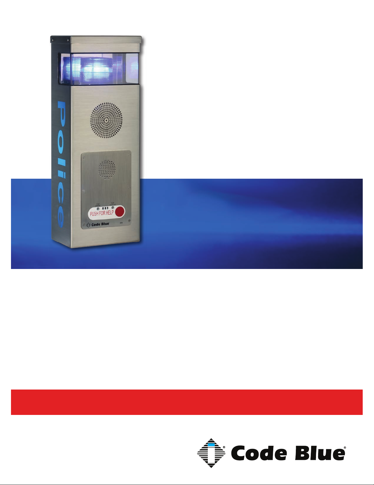
CB 2 Series
CB 2-e with AED Housing
CB 2-e with Public Address
Installation, Configuration, Operation & Troubleshooting
CB 2-e
CB 2-s
Administrator Guide
800.205.7186 • www.codeblue.com
Page 2

CB 2 Series
Administrator Guide
WARNING
ONLY QUALIFIED PERSONNEL SHOULD INSTALL THESE UNITS. THE INSTALLATION
SHOULD CONFORM TO ALL LOCAL CODES. IN SOME COUNTRIES, A CERTIFIED ELECTRICIAN MAY BE REQUIRED.
NOTICE TO USERS
Copyright © Code Blue Corporation. All rights reserved. This guide or software described herein, in
whole or part, shall not be reproduced, translated or reduced to any machine-readable form without
prior written approval from Code Blue Corporation.
CODE BLUE CORPORATION PROVIDES NO WARRANTY WITH REGARD TO THIS GUIDE, THE
SOFTWARE OR OTHER INFORMATION CONTAINED HEREIN AND HEREBY EXPRESSLY DISCLAIMS ANY IMPLIED WARRANTIES OF MERCHANTABILITY OR FITNESS FOR ANY PARTICULAR PURPOSE WITH REGARD TO THIS GUIDE, THE SOFTWARE OR SUCH OTHER INFORMATION. IN NO EVENT SHALL CODE BLUE CORPORATION BE LIABLE FOR ANY INCIDENTAL,
CONSEQUENTIAL, OR SPECIAL DAMAGES, WHETHER BASED ON TORT, CONTRACT, OR
OTHERWISE, ARISING OUT OF OR IN CONNECTIONS WITH THIS GUIDE, THE SOFTWARE
OR OTHER INFORMATION CONTAINED HEREIN OR THE USE THEREOF.
Code Blue Corporation reserves the right to make any modications to this guide or the information
contained herein at any time without notice. The software described herein may also be governed
by the terms of a separate user license agreement.
Code Blue® is a registered trademark of Code Blue Corporation.
Code Blue • 259 Hedcor Street • Holland, MI 49423 USA • 800.205.7186 • www.codeblue.com
GU-149-Gpage 2 of 43
Page 3

Administrator Guide
Table of Contents
Section Page
2 Introduction.................................................................................... 4
3 Getting Started............................................................................... 5
4 Spare Parts..................................................................................... 6
5 Power Requirements...................................................................... 8
6 Software Conguration..................................................................10
7 CB 2-e Low Voltage Exploded View...............................................11
8 CB 2-e High Voltage Exploded View..............................................12
9 CB 2-s Low Voltage Exploded View...............................................13
10 CB 2-s High Voltage Exploded View..............................................14
CB 2 Series
11 IP Color Camera Installation Instructions.................................... 15
12 CB 2-e Installation Instructions.....................................................16
13 CB 2-e with Public Address Installation Instructions..................17
14 CB 2-e with AED Housing Installation Instructions.....................22
15 CB 2-s Installation Instructions.....................................................25
16 Pole Mount Bracket Installation Instructions...............................28
17 AED Access and Maintenance Guide............................................29
18 S-1000/S-1050 Installation Instructions........................................30
19 PoE Installation Instructions.........................................................32
20 CB 5-s and CB 5-p Standard Wiring (with Hammond Transformer)...........33
21 CB 2-e Wiring Diagram...................................................................34
22 Cb 2-e with Public Address Wiring Diagram................................35
23 CB 2-e with AED Housing Wiring Diagram...................................36
24 CB 2-s Wiring Diagram...................................................................37
25 Multi Tap Transformer Wiring........................................................38
26 Maintenance Schedule...................................................................39
27 Locating Unit Serial Numbers........................................................41
28 Warranty...........................................................................................42
29 Download Information....................................................................43
Code Blue • 259 Hedcor Street • Holland, MI 49423 USA • 800.205.7186 • www.codeblue.com
GU-149-Gpage 3 of 43
Page 4
2 Introduction
CB 2 Series
Administrator Guide
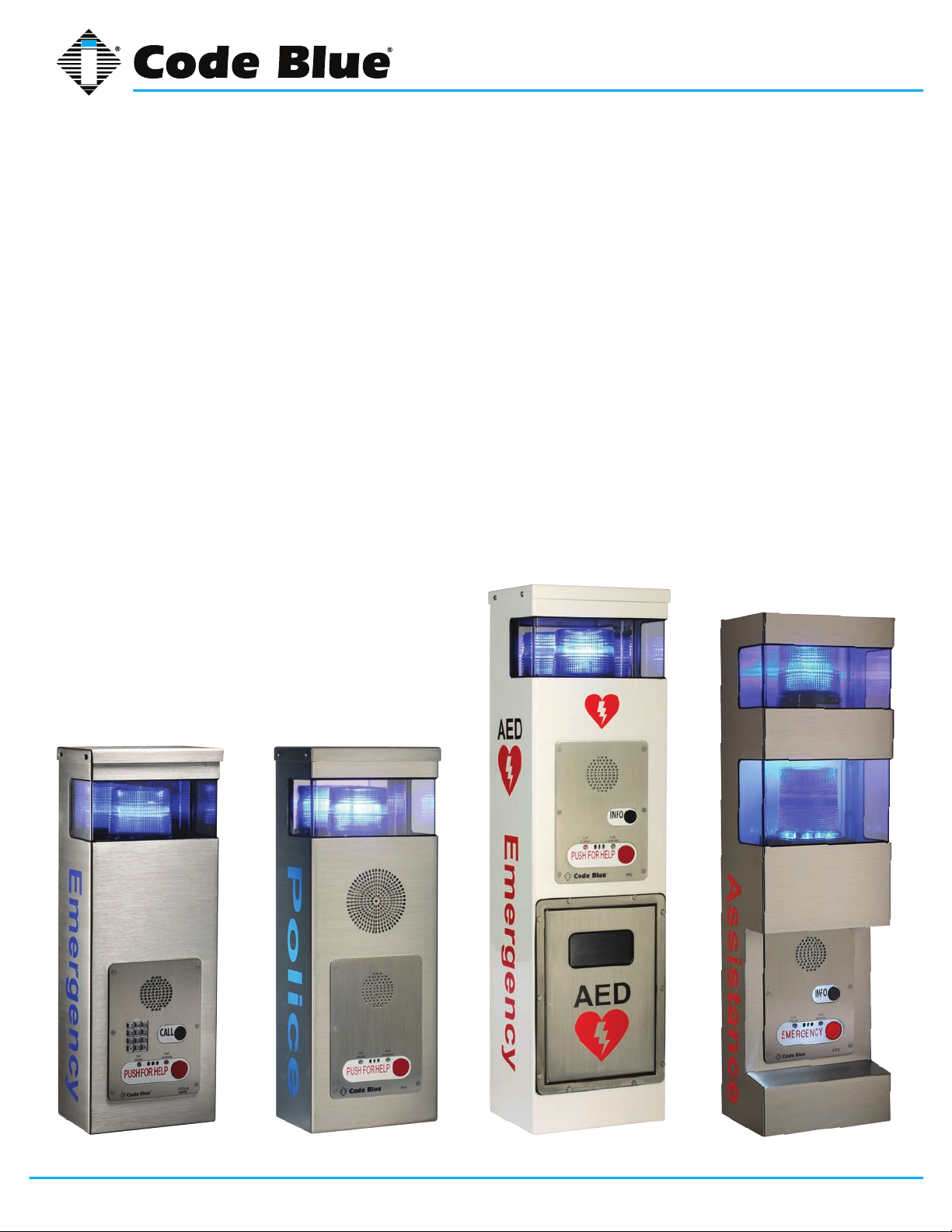
The 2 Series Wall Mount Help Points
This popular line is a good t for any indoor or outdoor application, including parking facilities. Our
unmistakable craftsmanship makes our Help Points® the most rugged on the market, withstanding
the punishment of natural and man-made disasters. All 2 Series units have a rugged steel construc-
tion, shatterproof Lexan Lens, industrial engineering grade reective graphics and weather, UV and
grafti resistant paint, and are illuminated by a high-powered, 270 lumens/92 candela LED blue
beacon/strobe. Other options include:
• IP and analog phones
• Long-life LED area light
• Low power consumption LED faceplate light
• Camera and card reader openings
• Temperature controlled automated external debrillator (AED) housing
• Public address speakers
®
CB 2-e CB 2-e with Public Address CB 2-e with AED Housing CB 2-s
Code Blue • 259 Hedcor Street • Holland, MI 49423 USA • 800.205.7186 • www.codeblue.com
GU-149-Gpage 4 of 43
Page 5

CB 2 Series
Administrator Guide
3 Getting Started
Basic Install Instructions
1. EIA/TIA, ANSI, CSA and BICSI cabling or similar standards shall be adhered to for proper
operation of Code Blue communication devices connected to copper or ber infrastructures.
Communications cable and electrical cable in the same conduit is not an acceptable instal lation and shall not be supported. Analog phones require a minimum of 23mA for proper
operation (26-29mA recommended).
2. Each analog speakerphone requires its own phone line or PBX extension. Multiple units
shall not be supported.
3. Speakerphones require programming before operation. Consult the User Guide or
Administrator Guide enclosed with the unit or visit www.codeblue.com > Support >
Downloads to read or download manuals.
4. If you are installing IP speakerphones, please read the appropriate manuals and consult
with your Network Administrator.
5. Size electrical wiring based on length of run.
6. Consult the enclosed document packet for internal wiring instructions.
Tools Required
CB 2 Series
1. Drill and security bit for removing and inserting security screws on phone and access plate
2. Phillips head screwdriver and at head screwdriver
3. 3/8 socket set to mount unit onto wall
Code Blue • 259 Hedcor Street • Holland, MI 49423 USA • 800.205.7186 • www.codeblue.com
GU-149-Gpage 5 of 43
Page 6
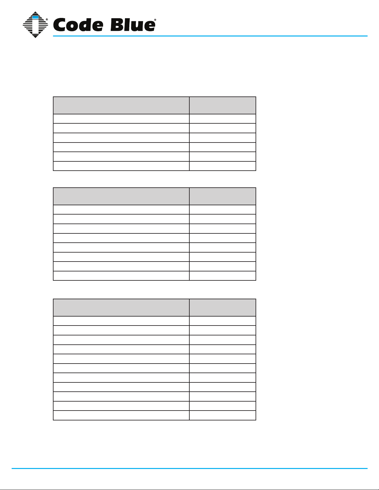
4 Spare Parts
CB 2-e
Part Part Number
LED Strobe Light 40159
Button Head Security Screws (3-pack) 41418
Analog Phone Line Surge Suppressor 41471
IP Phone Line Surge Suppressor 41421
Manifold R/B 5-way 40101
Power Brick 120V, 240V, 277V & 347V 40104
CB 2-e with Public Address
Part Part Number
CB 2 Series
Administrator Guide
LED Strobe Light 40159
Button Head Security Screws (3-pack) 41418
Analog Phone Line Surge Suppressor 41471
IP Phone Line Surge Suppressor 41421
Manifold R/B 5-way 40101
PAS AMP Kit 24V 40009
Power Brick 120V, 240V, 277V & 347V 40104
PAS Speaker 40080
CB 2-e with AED Housing
Part Part Number
LED Strobe Light 40159
Button Head Security Screws (3-pack) 41418
Analog Phone Line Surge Suppressor 41471
IP Phone Line Surge Suppressor 41421
Manifold R/B 5-way 40101
Power Brick 120V, 240V, 277V & 347V 40104
AED Housing Door Release Mechanism 41104
AED Housing Heater 41105
AED Housing Thermostat 41106
AED Housing Door Controller 41107
AED Housing Retrot kit 40012
Code Blue • 259 Hedcor Street • Holland, MI 49423 USA • 800.205.7186 • www.codeblue.com
GU-149-Gpage 6 of 43
Page 7
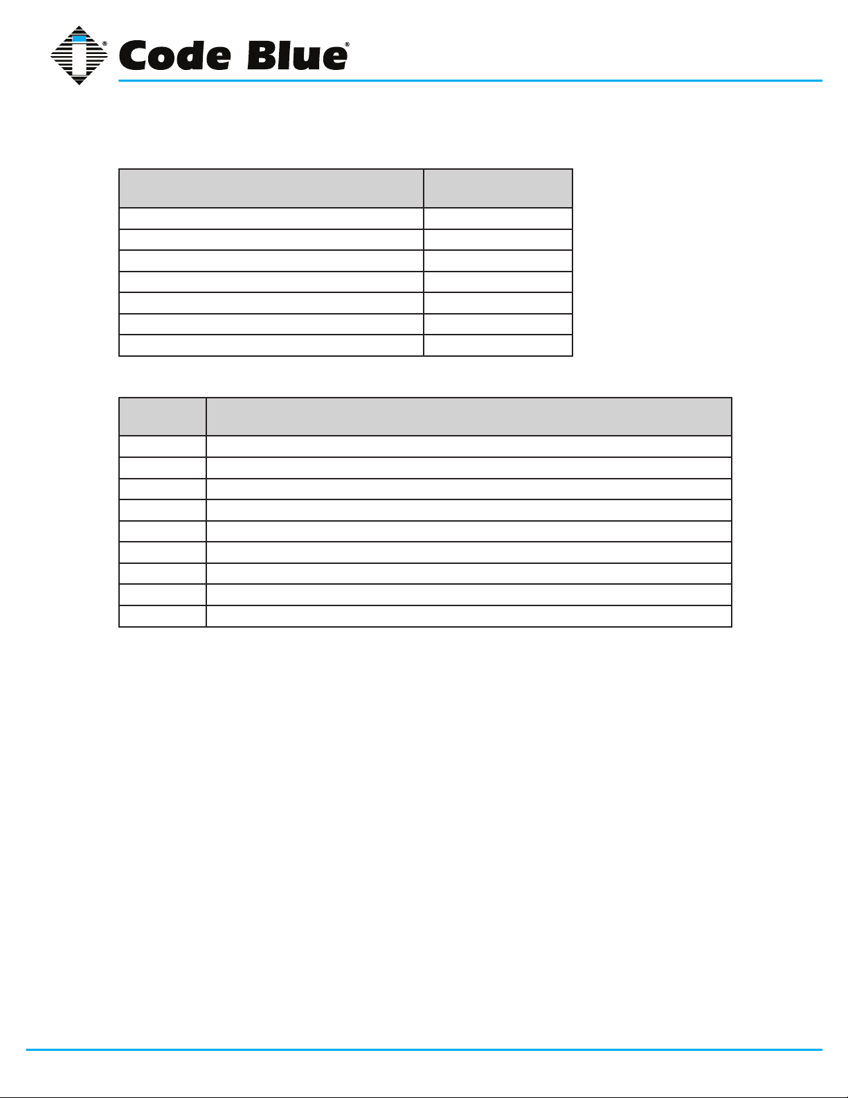
CB 2-s
Part Part Number
LED Strobe Light 40159
Button Head Security Screws (3-pack) 41418
Analog Phone Line Surge Suppressor 41471
IP Phone Line Surge Suppressor 41421
Manifold R/B 5-way 40101
Power Brick 120V, 240V, 277V & 347V 40104
LED Area Light 41539
CB 2 Series Additional Options
Quantity Part Description
1 Document packet (Installation and Setup)
1 Hardware packet
4 Lag screw sleeves
4 Metal washers
4 Rubber washers
1 Security bit
1 Enclosure (CB 2-e, CB 2-e with PAS, CB 2-e with AED or CB 2-s)
2 10/24 Counter sunk security screws – CB 2-s only
2 Key fobs – CB 2-e with AED only
CB 2 Series
Administrator Guide
Code Blue • 259 Hedcor Street • Holland, MI 49423 USA • 800.205.7186 • www.codeblue.com
GU-149-Gpage 7 of 43
Page 8
CB 2 Series
Administrator Guide
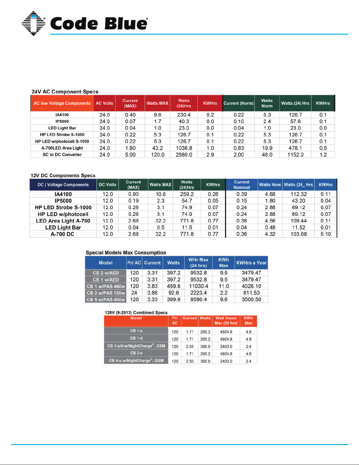
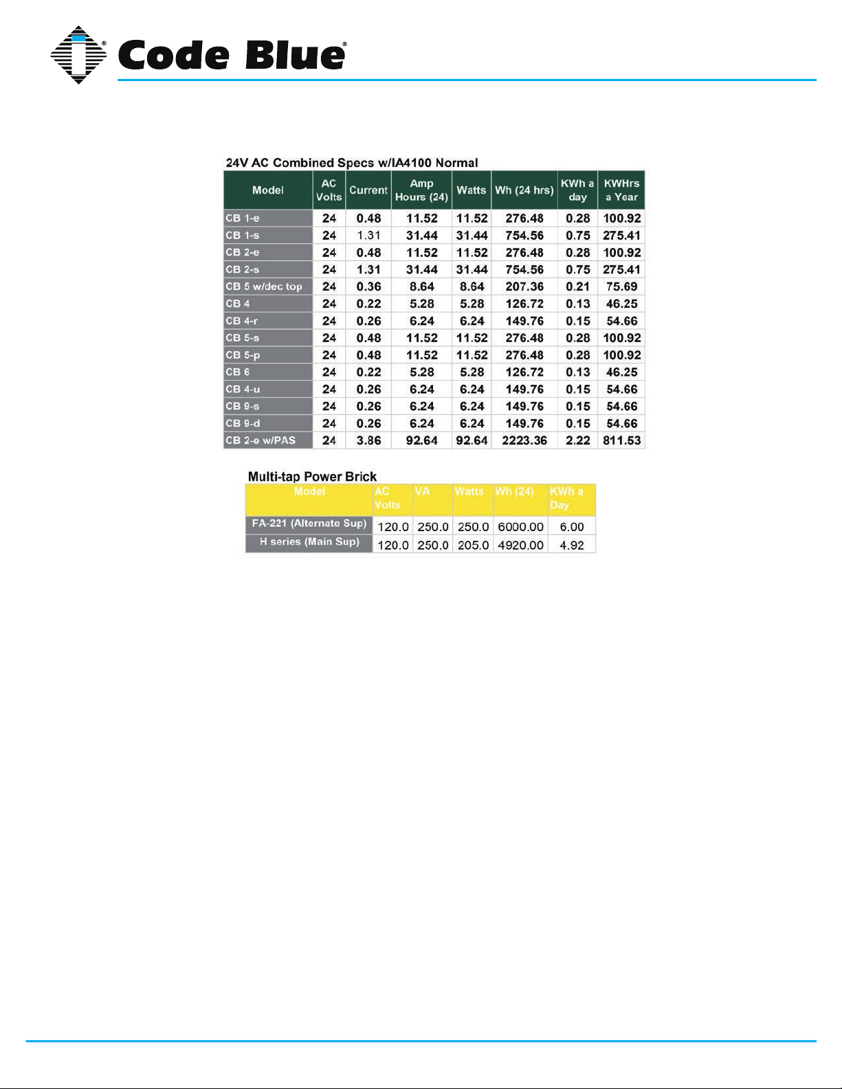
5 Power Requirements
(The following power requirements include the 2 Series and also ALL OTHER Code Blue units.)
Code Blue • 259 Hedcor Street • Holland, MI 49423 USA • 800.205.7186 • www.codeblue.com
GU-149-Gpage 8 of 43
Page 9
CB 2 Series
Administrator Guide
Code Blue • 259 Hedcor Street • Holland, MI 49423 USA • 800.205.7186 • www.codeblue.com
GU-149-Gpage 9 of 43
Page 10

CB 2 Series
Administrator Guide
6 Software Configuration
Blue Alert® MNS Software
Blue Alert MNS (Mass Notication Software) lls a need in the marketplace for an incident response
solution that is both comprehensive and cost-effective, while also providing an efcient way to detect
and respond. The advanced mass notication system allows responders to deliver multi-layered
emergency notications via a wide range of platforms, including email, text message (SMS), emer-
gency phones, public address speakers, social media, desktop alerts and more, quickly informing
and directing people in emergency situations.
Blue Alert® EMS
Blue Alert EMS is an advanced software solution that handles all incoming events effectively by remotely controlling emergency communication devices with an easy-to-use Graphical User Interface
(GUI). You also will have the ability to open gates and AED access doors, turn LED beacon/strobes
on or off, transfer calls to Public Address Systems to make area wide announcements and incorporate other ancillary devices and applications while the system securely archives data for future
reference.
ToolVox®
A sophisticated emergency management platform for your blue light phone network, ToolVox offers
unique real-time monitoring and provisioning options for emergency phones and public address
speakers, effectively acting as a hub for connecting Help Points® and other Code Blue devices. Using our proprietary incident response software, Blue Alert® MNS and EMS, you can send alerts via
outdoor platforms, such as blue light phones and public address speakers. It also provides connec-
tions to PBX, public telephone (PSTN) and Internet (ISP) networks, in addition to third party security
platforms.
Code Blue • 259 Hedcor Street • Holland, MI 49423 USA • 800.205.7186 • www.codeblue.com
GU-149-Gpage 10 of 43
Page 11
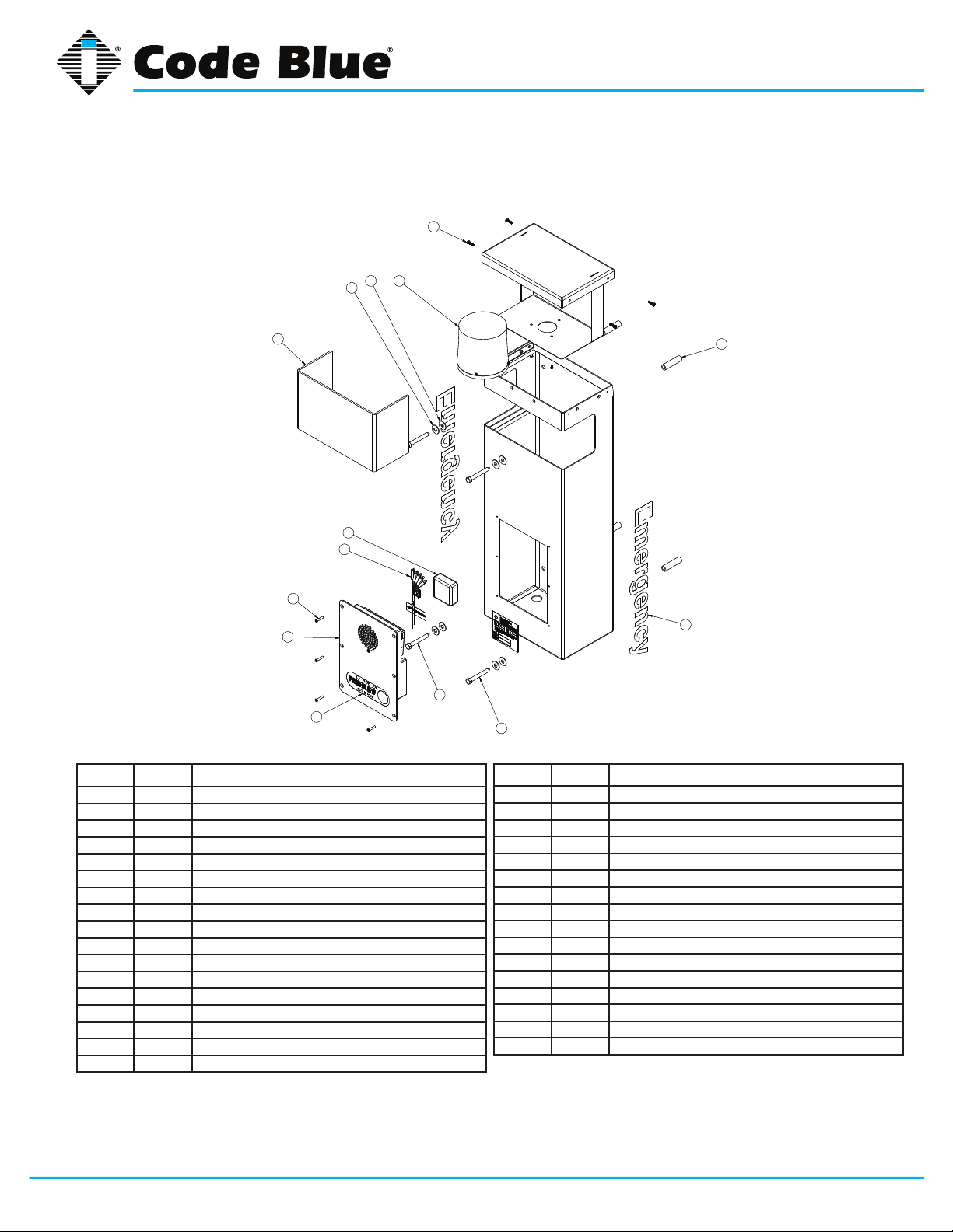
7 CB 2-e Low Voltage Exploded View
3
3
244
4
4
1
1
244
CB 2 Series
Administrator Guide
5
5
9
9
8
8
7
7
10
10
BALL # PART # DESCRIPTION
1 41425 HID Lens
2 40159 LED Beacon Strobe
3 41418 Button head Security Screw (3 pk)
4 40102 Wall Anchor Kit
5 41471 Analog Surge Suppressor
5 41421 IP Surge Suppressor
6 CALL Standard / Custom Graphic
7 50001 Single Button IA4100 Analog Phone – PUSH FOR HELP
7 50002 Double Button IA4100 Analog Phone – PUSH FOR HELP
7 50003 Keypad IA4100 Analog Phone – PUSH FOR HELP
7 50004 Single Button IA4100 Analog Phone – EMERGENCY
7 50005 Double Button IA4100 Analog Phone – EMERGENCY
7 50006 Keypad IA4100 Analog Phone – EMERGENCY
7 50007 Single Button IA4100 Analog Phone – EMERGENCY/EMERGENCIA
7 50008 Double Button IA4100 Analog Phone – EMERGENCY/EMERGENCIA
7 50009 Keypad IA4100 Analog Phone – EMERGENCY/EMERGENCIA
7 50101 Single Button IP5000 Phone – PUSH FOR HELP
6
6
4
4
4
4
BALL # PART # DESCRIPTION
7 50102 Double Button IP5000 Phone – PUSH FOR HELP
7 50103 Keypad IP5000 Phone – PUSH FOR HELP
7 50104 Single Button IP5000 Phone – EMERGENCY
7 50105 Double Button IP5000 Phone – EMERGENCY
7 50106 Keypad IP5000 Phone – EMERGENCY
7 50107 Single Button IP5000 Phone – EMERGENCY/EMERGENCIA
7 50108 Double Button IP5000 Phone – EMERGENCY/EMERGENCIA
7 50109 Keypad IP5000 Phone – EMERGENCY/EMERGENCIA
8 41544 Faceplate Security Screw 10x24 (6 pk)
9 40101 Manifold R/B 5-way
10 40357 Bezel Assembly IA4100 Analog Phone – PUSH FOR HELP
10 40407 Bezel Assembly IA4100 Analog Phone – EMERGENCY
10 40408 Bezel Assembly IA4100 Analog Phone – EMERGENCY/EMERGENCIA
10 40313 Bezel Assembly IP5000 Analog Phone – PUSH FOR HELP
10 40405 Bezel Assembly IP5000 Analog Phone – EMERGENCY
10 40406 Bezel Assembly IP5000 Analog Phone – EMERGENCY/EMERGENCIA
DISCLAIMER: Product design and component use subject to change without notice. Product shown reasonably represents current offering and
is intended to assist in component identication. Reference the model and serial number from the unit ID tag and contact manufacturer to conrm
replacement part version and availability.
Code Blue • 259 Hedcor Street • Holland, MI 49423 USA • 800.205.7186 • www.codeblue.com
GU-149-Gpage 11 of 43
Page 12
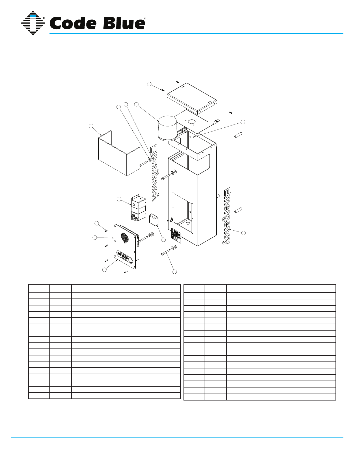
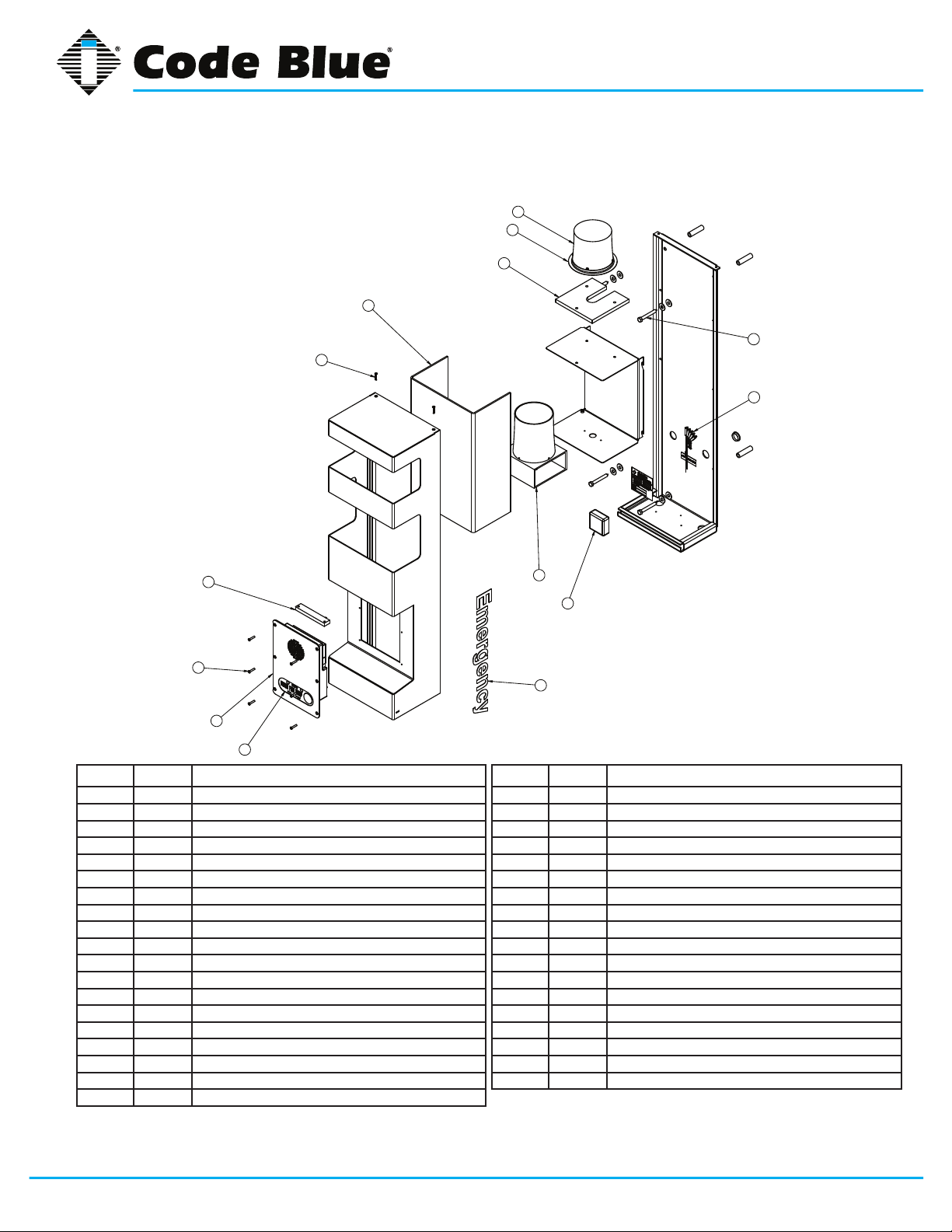
8 CB 2-e High Voltage Exploded View
3
3
2
4
2
4
4
4
1
1
CB 2 Series
Administrator Guide
3
3
9
9
8
8
7
7
10
10
BALL # PART # DESCRIPTION
1 41425 HID Lens
2 40159 LED Beacon Strobe
3 41418 Button Head Security Screws (3 pk)
4 40102 Wall Anchor Kit
5 41471 Analog Surge Suppressor
5 41421 IP Surge Suppressor
6 CALL Standard Graphic
6 CALL Custom Graphic
7 50001 Single Button IA4100 Analog Phone – PUSH FOR HELP
7 50002 Double Button IA4100 Analog Phone – PUSH FOR HELP
7 50003 Keypad IA4100 Analog Phone – PUSH FOR HELP
7 50004 Single Button IA4100 Analog Phone – EMERGENCY
7 50005 Double Button IA4100 Analog Phone – EMERGENCY
7 50006 Keypad IA4100 Analog Phone – EMERGENCY
7 50007 Single Button IA4100 Analog Phone – EMERGENCY/EMERGENCIA
7 50008 Double Button IA4100 Analog Phone – EMERGENCY/EMERGENCIA
7 50009 Keypad IA4100 Analog Phone – EMERGENCY/EMERGENCIA
6
6
5
5
4
4
BALL # PART # DESCRIPTION
7 50101 Single Button IP5000 Phone – PUSH FOR HELP
7 50102 Double Button IP5000 Phone – PUSH FOR HELP
7 50103 Keypad IP5000 Phone – PUSH FOR HELP
7 50104 Single Button IP5000 Phone – EMERGENCY
7 50105 Double Button IP5000 Phone – EMERGENCY
7 50106 Keypad IP5000 Phone – EMERGENCY
7 50107 Single Button IP5000 Phone – EMERGENCY/EMERGENCIA
7 50108 Double Button IP5000 Phone – EMERGENCY/EMERGENCIA
7 50109 Keypad IP5000 Phone – EMERGENCY/EMERGENCIA
8 41544 Faceplate Security Screw 10x24 (6 pk)
9 40104 Power Brick 120V, 240V, 277V, 347V
10 40357 Bezel Assembly IA4100 Analog Phone – PUSH FOR HELP
10 40407 Bezel Assembly IA4100 Analog Phone – EMERGENCY
10 40408 Bezel Assembly IA4100 Analog Phone – EMERGENCY/EMERGENCIA
10 40313 Bezel Assembly IP5000 Analog Phone – PUSH FOR HELP
10 40405 Bezel Assembly IP5000 Analog Phone – EMERGENCY
10 40406 Bezel Assembly IP5000 Analog Phone – EMERGENCY/EMERGENCIA
DISCLAIMER: Product design and component use subject to change without notice. Product shown reasonably represents current offering and
is intended to assist in component identication. Reference the model and serial number from the unit ID tag and contact manufacturer to conrm
replacement part version and availability.
Code Blue • 259 Hedcor Street • Holland, MI 49423 USA • 800.205.7186 • www.codeblue.com
GU-149-Gpage 12 of 43
Page 13
9 CB 2-s Low Voltage Exploded View
10
11
12
9
8
CB 2 Series
Administrator Guide
13
14
4
3
2
1
BALL # PART # DESCRIPTION
1 40357 Bezel Assembly IA4100 Analog Phone – PUSH FOR HELP
1 40407 Bezel Assembly IA4100 Analog Phone – EMERGENCY
1 40408 Bezel Assembly IA4100 Analog Phone – EMERGENCY/EMERGENCIA
1 40313 Bezel Assembly IP5000 Analog Phone – PUSH FOR HELP
1 40405 Bezel Assembly IP5000 Analog Phone – EMERGENCY
1 40406 Bezel Assembly IP5000 Analog Phone – EMERGENCY/EMERGENCIA
2 50001 Single Button IA4100 Analog Phone – PUSH FOR HELP
2 50002 Double Button IA4100 Analog Phone – PUSH FOR HELP
2 50003 Keypad IA4100 Analog Phone – PUSH FOR HELP
2 50004 Single Button IA4100 Analog Phone – EMERGENCY
2 50005 Double Button IA4100 Analog Phone – EMERGENCY
2 50006 Keypad IA4100 Analog Phone – EMERGENCY
2 50007 Single Button IA4100 Analog Phone – EMERGENCY/EMERGENCIA
2 50008 Double Button IA4100 Analog Phone – EMERGENCY/EMERGENCIA
2 50009 Keypad IA4100 Analog Phone – EMERGENCY/EMERGENCIA
2 50101 Single Button IP5000 Phone – PUSH FOR HELP
2 50102 Double Button IP5000 Phone – PUSH FOR HELP
2 50103 Keypad IP5000 Phone – PUSH FOR HELP
7
6
5
BALL # PART # DESCRIPTION
2 50105 Double Button IP5000 Phone – EMERGENCY
2 50106 Keypad IP5000 Phone – EMERGENCY
2 50107 Single Button IP5000 Phone – EMERGENCY/EMERGENCIA
2 50108 Double Button IP5000 Phone – EMERGENCY/EMERGENCIA
2 50109 Keypad IP5000 Phone – EMERGENCY/EMERGENCIA
3 41544 Faceplate Security Screw 10x24 (6 pk)
4 41548 LED Faceplate Light
5 CALL Standard / Custom Graphic
6 41471 Analog Surge Suppressor
6 41421 IP Surge Suppressor
7 41539 LED Area Light
8 41544 Faceplate Security Screw 10x24 (6 pk)
9 41412 HID Lens
10 40159 LED Blue Beacon Strobe
11 40543 Strobe Disk (3 pk)
12 10084 Clear Strobe Spacer
13 40102 Wall Mount Hardware Kit
14 40101 Manifold R/B 5-way
2 50104 Single Button IP5000 Phone – EMERGENCY
DISCLAIMER: Product design and component use subject to change without notice. Product shown reasonably represents current offering and
is intended to assist in component identication. Reference the model and serial number from the unit ID tag and contact manufacturer to conrm
replacement part version and availability.
Code Blue • 259 Hedcor Street • Holland, MI 49423 USA • 800.205.7186 • www.codeblue.com
GU-149-Gpage 13 of 43
Page 14

10 CB 2-s High Voltage Exploded View
10
11
12
9
8
CB 2 Series
Administrator Guide
13
14
4
3
2
1
BALL # PART # DESCRIPTION
1 40357 Bezel Assembly IA4100 Analog Phone – PUSH FOR HELP
1 40407 Bezel Assembly IA4100 Analog Phone – EMERGENCY
1 40408 Bezel Assembly IA4100 Analog Phone – EMERGENCY/EMERGENCIA
1 40313 Bezel Assembly IP5000 Analog Phone – PUSH FOR HELP
1 40405 Bezel Assembly IP5000 Analog Phone – EMERGENCY
1 40406 Bezel Assembly IP5000 Analog Phone – EMERGENCY/EMERGENCIA
2 50001 Single Button IA4100 Analog Phone – PUSH FOR HELP
2 50002 Double Button IA4100 Analog Phone – PUSH FOR HELP
2 50003 Keypad IA4100 Analog Phone – PUSH FOR HELP
2 50004 Single Button IA4100 Analog Phone – EMERGENCY
2 50005 Double Button IA4100 Analog Phone – EMERGENCY
2 50006 Keypad IA4100 Analog Phone – EMERGENCY
2 50007 Single Button IA4100 Analog Phone – EMERGENCY/EMERGENCIA
2 50008 Double Button IA4100 Analog Phone – EMERGENCY/EMERGENCIA
2 50009 Keypad IA4100 Analog Phone – EMERGENCY/EMERGENCIA
2 50101 Single Button IP5000 Phone – PUSH FOR HELP
2 50102 Double Button IP5000 Phone – PUSH FOR HELP
2 50103 Keypad IP5000 Phone – PUSH FOR HELP
7
6
5
BALL # PART # DESCRIPTION
2 50105 Double Button IP5000 Phone – EMERGENCY
2 50106 Keypad IP5000 Phone – EMERGENCY
2 50107 Single Button IP5000 Phone – EMERGENCY/EMERGENCIA
2 50108 Double Button IP5000 Phone – EMERGENCY/EMERGENCIA
2 50109 Keypad IP5000 Phone – EMERGENCY/EMERGENCIA
3 41544 Faceplate Security Screw 10x24 (6 pk)
4 41548 LED Faceplate Light
5 CALL Standard / Custom Graphic
6 41471 Analog Surge Suppressor
6 41421 IP Surge Suppressor
7 41539 LED Area Light
8 41544 Faceplate Security Screw 10x24 (6 pk)
9 41412 HID Lens
10 40159 LED Blue Beacon Strobe
11 40543 Strobe Disk (3 pk)
12 10084 Clear Strobe Spacer
13 40102 Wall Mount Hardware Kit
14 40105 Power Brick 120V, 240V, 277V, 347V
2 50104 Single Button IP5000 Phone – EMERGENCY
DISCLAIMER: Product design and component use subject to change without notice. Product shown reasonably represents current offering and
is intended to assist in component identication. Reference the model and serial number from the unit ID tag and contact manufacturer to conrm
replacement part version and availability.
Code Blue • 259 Hedcor Street • Holland, MI 49423 USA • 800.205.7186 • www.codeblue.com
GU-149-Gpage 14 of 43
Page 15

CB 2 Series
Administrator Guide
11 IP Color Camera Installation Instructions
Color IP Camera Option
HIKVISION Network Mini Dome Camera for Second Opening
The HIKVISION Mini Dome Network IP Camera installed in this unit is a Code Blue 3rd Party Partner product. Model # DS-2CD7153-E.
The network camera is set with the following factory default settings:
• IP Address: 192.0.0.64
• Camera is accessed on IP Port 8000
• User Name: admin
• Password: 12345
For additional support, contact HIKVISION at:
Website: http://www.hikvision-usa.com/support.html
Phone: 1-909-895-0400, 6 a.m. to 6 p.m. PST
Email: techsupport@hikvisionusa.com
Note: Please contact Code Blue Customer Service if a custom cutout is needed on the CB 9-d for
third party products, such as a card reader or a custom camera to mount on the second opening
plate.
Contact Code Blue Customer Service at 800-205-7186 or customerservice@codeblue.com.
Code Blue • 259 Hedcor Street • Holland, MI 49423 USA • 800.205.7186 • www.codeblue.com
GU-149-Gpage 15 of 43
Page 16

CB 2 Series
Administrator Guide
12 CB 2-e Installation Instructions
1.0 PRE-INSTALLATION
1.1 Electrical preparation – The unit may have supply wires run from either (a) behind the unit
through the wall, or (b) below the unit using an external conduit through the bottom of the
unit. Holes in the back and bottom of the unit have been provided for this purpose.
2.0 INSTALLATION PROCEDURES
2.1 Remove the top of the unit.
2.2 Mark the mounting holes – In order to comply with the Americans with Disabilities Act
(ADA) of 1990, the speakerphone button(s) should be positioned between 34 and 48 inches
from grade level. (Consult an ADA specialist in your area to verify local and federal guidelines.)
2.3 Drill all marked holes.
2.4 Install the housing – Four anchors of appropriate size and type should be used to fasten
the housing to the wall.
IMPORTANT: If wiring is supplied from the back, ensure that the conduit is aligned at this
time.
2.5 Reattach the top.
3.0 WIRING
3.1 Ground – The ground (green) wire should be stripped and fastened to the supplied ground-
ing lug.
3.2 24V AC supply – Using the proper crimping tool, attach a #8 fork to each of the incoming
power wires and fasten them to the terminal screws labeled “Line” and “Neutral.”
3.3 120/240V AC supply – Using the proper crimping tool, attach a #8 fork to each of the in-
coming power wires and fasten them to the correct terminals as labeled on the transformer.
After completing the wire connections, install the supplied terminal covers.
See diagrams next page
Code Blue • 259 Hedcor Street • Holland, MI 49423 USA • 800.205.7186 • www.codeblue.com
GU-149-Gpage 16 of 43
Page 17

CB 2 Series
Administrator Guide
Code Blue • 259 Hedcor Street • Holland, MI 49423 USA • 800.205.7186 • www.codeblue.com
GU-149-Gpage 17 of 43
Page 18

CB 2 Series
Administrator Guide
Suggested installation dimensions shown from ground to lower right mounting hole are for single button faceplates.
• For dual button faceplate, deduct 3.25 inches.
• For keypad faceplate, deduct 4.5 inches.
• For wheelchair direct facing access only, deduct 6 inches.
DISCLAIMER: The dimensions above are intended as guidelines only. For specic installation requirements,
reference your local codes.
All wiring must be installed and connected by experienced and certied personnel to meet
local and national electrical codes, and will include a service disconnect.
Code Blue • 259 Hedcor Street • Holland, MI 49423 USA • 800.205.7186 • www.codeblue.com
GU-149-Gpage 18 of 43
Page 19

CB 2 Series
Administrator Guide
13 CB 2-e with Public Address Installation Instructions
1.0 PRE-INSTALLATION
1.1 Electrical preparation – The unit may have supply wires run from either (a) behind the unit
through the wall, or (b) below the unit using an external conduit through the bottom of the unit.
Holes in the back and bottom of the unit have been provided for this purpose.
2.0 INSTALLATION PROCEDURES
2.1 Remove the top of the unit.
2.2 Mark the mounting holes – In order to comply with the Americans with Disabilities Act (ADA)
of 1990, the speakerphone button(s) should be positioned between 34 and 48 inches from
grade level. (Consult an ADA specialist in your area to verify local and federal guidelines.)
2.3 Drill all marked holes.
2.4 Install the housing – Four anchors of appropriate size and type should be used to fasten the
housing to the wall.
IMPORTANT: If wiring is supplied from the back, ensure that the conduit is aligned at this time.
2.5 Reattach the top.
3.0 ELECTRICAL WIRING
3.1 Ground – The ground (green) wire should be stripped and fastened to the supplied grounding
lug.
3.2 24V AC supply – Using the proper crimping tool, attach a #8 fork to each of the incoming
power wires and fasten them to the terminal screws labeled “Line” and “Neutral.”
3.3 120/240V AC supply – Using the proper crimping tool, attach a #8 fork to each of the incom-
ing power wires and fasten them to the correct terminals as labeled on the transformer. After
completing the wire connections install the supplied terminal covers.
4.0 COMMUNICATIONS WIRING
4.1 Have category 3 or higher 4-pair cable terminated to a RJ45 applying TIA/EIA T568-B speci-
cations.
See diagrams next page
Code Blue • 259 Hedcor Street • Holland, MI 49423 USA • 800.205.7186 • www.codeblue.com
GU-149-Gpage 19 of 43
Page 20

CB 2 Series
Administrator Guide
Code Blue • 259 Hedcor Street • Holland, MI 49423 USA • 800.205.7186 • www.codeblue.com
GU-149-Gpage 20 of 43
Page 21

CB 2 Series
Administrator Guide
Suggested installation dimensions shown from ground to lower right mounting hole are for single button faceplates.
• For dual button faceplate, deduct 3.25 inches.
• For keypad faceplate, deduct 4.5 inches.
• For wheelchair direct facing access only, deduct 6 inches.
DISCLAIMER: The dimensions above are intended as guidelines only. For specic installation requirements,
reference your local codes.
All wiring must be installed and connected by experienced and certied personnel to meet
local and national electrical codes, and will include a service disconnect.
Code Blue • 259 Hedcor Street • Holland, MI 49423 USA • 800.205.7186 • www.codeblue.com
GU-149-Gpage 21 of 43
Page 22

CB 2 Series
Administrator Guide
14 CB 2-e with AED Housing Installation Instructions
1.0 PRE-INSTALLATION
1.1 Electrical preparation – The unit may have supply wires run from either (a) behind the
unit through the wall, or (b) below the unit using an external conduit through the bottom of
the unit. Holes in the back and bottom of the unit have been provided for this purpose (see
Figure 1).
2.0 INSTALLATION PROCEDURES
2.1 Remove the top of the unit.
2.2 Mark the mounting holes – In order to comply with the Americans with Disabilities Act
(ADA) of 1990, the speakerphone button(s) should be positioned between 34 and 48 inches
from grade level. (Consult an ADA specialist in your area to verify local and federal guidelines.)
2.3 Drill all marked holes.
2.4 Install the housing – Four anchors of appropriate size and type should be used to fasten
the housing to the wall.
IMPORTANT: If wiring is supplied from the back, ensure that the conduit is aligned at this
time.
2.5 Reattach the top.
3.0 WIRING
3.1 120/240V AC supply – Feed the incoming power leads into the supplied J-Box. Connect the
ground to the supplied grounding lug. Connect the neutral to the orange lead for fusing the
unit. Connect the load to the black wires. After completing the wire connections, install the
supplied J-Box cover and ensure all cord grips are secure.
See diagrams next page
Code Blue • 259 Hedcor Street • Holland, MI 49423 USA • 800.205.7186 • www.codeblue.com
GU-149-Gpage 22 of 43
Page 23

12.53
23.06
CB 2 Series
Administrator Guide
8.00
36.00
46.72
21.00
15.5
3.00
9.00
11
Code Blue • 259 Hedcor Street • Holland, MI 49423 USA • 800.205.7186 • www.codeblue.com
GU-149-Gpage 23 of 43
Page 24

Administrator Guide
Ø .44 MOUNTING HOLES
4 PLCS
CB 2 Series
45.22
28.00
KNOCKOUTS FOR
BOTTOM
GROUND LEVEL
Ø 1.13
2 PLCS
Ø
3/4 CONDUIT
36.00
8.00
21.00
3.00
9.00
12.40
THRU BOTTOM PLATE FOR
Ø 1.13
2 PLCS
Ø
3/4 CONDUIT
2.20
REF
8.00
1.62
Suggested installation dimensions shown from ground to lower right mounting hole are for single button faceplates.
• For dual button faceplate, deduct 3.25 inches.
• For keypad faceplate, deduct 4.5 inches.
• For wheelchair direct facing access only, deduct 6 inches.
DISCLAIMER: The dimensions above are intended as guidelines only. For specic installation requirements,
reference your local codes.
All wiring must be installed and connected by experienced and certied personnel to meet
Code Blue • 259 Hedcor Street • Holland, MI 49423 USA • 800.205.7186 • www.codeblue.com
local and national electrical codes, and will include a service disconnect.
MOUNTING SURFACE
GU-149-Gpage 24 of 43
Page 25

CB 2 Series
Administrator Guide
15 CB 2-s Installation Instructions
1.0 PRE-INSTALLATION
1.1 Running the wires – Wires to the unit may be run either (a) from behind the unit through
the wall, or (b) from below the unit using an external conduit through the bottom of the unit’s
back plate. Holes in the back and bottom of the unit have been provided for this purpose.
2.0 INSTALLATION PROCEDURES
2.1 Remove the light bracket and outer shell from the back plate.
2.2 Mark the mounting holes – In order to comply with the Americans with Disabilities Act
(ADA) of 1990, the speakerphone button(s) should be positioned between 34 and 48 inches
from grade level. (Consult an ADA specialist in your area to verify local and federal guidelines.)
2.3 Install the back plate – Four anchors should securely fasten the back plate to the wall.
IMPORTANT: If wiring is coming in from the back, ensure that the conduit is aligned at this
time.
2.4 Reattach the light bracket.
2.5 Reattach the outer shell – Holding the shell horizontal, hook the bottom hinge into the bot-
tom of the back plate. Swing the shell up and fasten the safety cable to the eyehook.
2.6 Connect electrical and communications wiring (see wiring instructions).
2.7 Close the unit – Fasten the outer shell to the back plate using two #10 countersunk secu-
rity screws.
See diagrams next page
Code Blue • 259 Hedcor Street • Holland, MI 49423 USA • 800.205.7186 • www.codeblue.com
GU-149-Gpage 25 of 43
Page 26

CB 2 Series
Administrator Guide
Code Blue • 259 Hedcor Street • Holland, MI 49423 USA • 800.205.7186 • www.codeblue.com
GU-149-Gpage 26 of 43
Page 27

CB 2 Series
Administrator Guide
42 REF
2 X Ø1-1/8
(KNOCKOUTS FOR
Ø3/4 CONDUIT)
12 REF
4 X Ø7/16 MOUNTING HOLES
30 3/4
2 9/16
8 5/16 REF
1 1/2 REF
6
9
1 1/2
43
GROUND/FLOOR
Suggested installation dimensions shown from ground to lower right mounting hole are for single button faceplates.
• For dual button faceplate, deduct 3.25 inches.
• For keypad faceplate, deduct 4.5 inches.
• For wheelchair direct facing access only, deduct 6 inches.
DISCLAIMER: The dimensions above are intended as guidelines only. For specic installation requirements,
reference your local codes.
All wiring must be installed and connected by experienced and certied personnel to meet
local and national electrical codes, and will include a service disconnect.
Code Blue • 259 Hedcor Street • Holland, MI 49423 USA • 800.205.7186 • www.codeblue.com
GU-149-Gpage 27 of 43
Page 28

CB 2 Series
B
A
C
D
E
F
CB-2e BACKPLATE
Pole Mount Instructions
CB 2-e
Administrator Guide
16 Pole Mount Bracket Installation Instructions
1.0 THREAD MOUNTING STRAPS THROUGH SLOTS
1.1 Thread mounting straps through slots for any size poles.
2.0 HOLD BRACKET TO POLE
2.1 Set the height of the bracket (C) so that the speakerphone push button(s) on the unit will be
at desired height (please check with local codes for ADA compliance).
3.0 BAND THE BRACKET TO THE POLE AT DESIRED HEIGHT
3.1 To eliminate waste, pull band (A) from carton as needed. With ears of buckle (B) away from
operator, slide
the buckle on the banding. Lace banding around the object being clamped and again
through buckle.
3.2 Bend end of band under buckle.
3.3 Slide band into banding tool nose slot.
3.4 When maximum tension has been reached, roll tool over buckle. At same time reversing
handle carefully
approximately ¾ turn to avoid breakage. The band that is released will be used in the bend
and therefore
there is no loss of tension.
3.5 Lift cutter lever and band will be cut to correct length.While holding the stub of the band with
your thumb,
hammer at over bridge of buckle.
3.6 Complete application by hammering the buckle ears over the stub.
4.0 ATTACH ENCLOSURE TO BRACKET
4.1 Place a rubber washer (D) on each of the four studs.
4.2 Align and place the back plate of the unit over the four studs.
4.3 Place a second set of rubber washers on to each of the four studs (inside the unit).
4.4 Place a steel washer (E) on each of the four studs.
4.5 Turn a nut (F) on each of the four studs.
Banding tool sold
separately on the
Parts Order Form,
part #41441.
Code Blue • 259 Hedcor Street • Holland, MI 49423 USA • 800.205.7186 • www.codeblue.com
GU-149-Gpage 28 of 43
Page 29

CB 2 Series
Administrator Guide
17 AED Access and Maintenance Guide
The following four methods can be used to access the Automated External Debrillator (AED)
device:
1. When the red button is depressed, the unit will make a call. After the call has been an swered, the answering party can then depress the 6 key on their telephone keypad. This will
release the door latch, giving the caller access to the AED device.
2. The units have a key fob supplied at the time of purchase. This key fob can be used within
approximately a 20-foot radius to release the door latch, giving the caller access to the AED
device.
3. The unit can be called and placed into two-way monitor mode. At this time, the person call
ing the unit can depress the 6 key on their telephone keypad which, will provide access to
the AED device.
4. The access panel on the back of the Code Blue unit is removed and the manual latch re
lease is pulled, granting access to the AED device.
Typically, AED manufacturers recommend that the device be checked once per week for proper operation. Some units will give an audible “chirp” if the self diagnostics have failed and the unit needs
service; others may use another indicator to verity its status. Refer to manufacturers’ maintenance
instructions for correct diagnostic testing to ascertain whether the device requires service or not.
In addition, review the manufacturer’s replacement policy for pad and battery replacement. Pay
close attention to the AED temperature specications and note that the life of the AED battery can
be greatly affected by extreme heat or cold environments, reducing the capacity by up to 50 percent.
Code Blue • 259 Hedcor Street • Holland, MI 49423 USA • 800.205.7186 • www.codeblue.com
GU-149-Gpage 29 of 43
Page 30

18 S-1000/S-1050 Installation Instructions
NOTE: Instructions pertain to
Model S-1000 LED Beacon/Strobe and
Model S-1050 LED Beacon/Strobe only
CB 2 Series
Administrator Guide
M3159-R/BK
M3159-Y/Y
DRY CONTACT
CLOSED = "ON"
RED
BLACK
YELLOW (FLASH MODE)
YELLOW (FLASH MODE)
POSITIVE (12-24V DC or AC)
COMMON (GROUND)
CAUTION: REMOVE ALL POWER FROM UNIT BEFORE SERVICING.
ATTENTION: WHEN REPLACING A BEACON/STROBE ON THE MODEL CB 5
SERIES ONLY, MOUNTING SCREW THREADS MUST BE COATED TO PREVENT
WATER LEAKAGE INTO THE UNIT.
OPERATION
To activate the LEDs in the PRIMARY-STEADYBURN MODE, connect the BLACK and RED
wires to 12-24 volts AC or DC.
When in PRIMARY-STEADYBURN MODE, to change the LEDs to SECONDARY-FLASH MODE,
connect both YELLOW control wires together (i.e., CLOSED = ON).
PHOTOCELL FEATURE (S-1050 MODEL)
The Steadyburn Mode will be ON in dark or night ambient environments and OFF in bright or
daylight ambient environments. The S-1050 LED Beacon/Strobe has two built-in photo response
features: (a) dawn/dusk transition delay of 15-30 minutes and (b) transient light acknowledgement
delay of at least 3 minutes.
Code Blue • 259 Hedcor Street • Holland, MI 49423 USA • 800.205.7186 • www.codeblue.com
GU-149-Gpage 30 of 43
Page 31

CB 2 Series
Administrator Guide
PROGRAMMING PRIMARY & SECONDARY MODES
1. Remove power from unit.
2. Short the Yellow wires together.
3. Restore power to the unit and wait until the unit begins to ash. Once the unit begins to ash,
remove the short. The unit will alternately demonstrate the Secondary-Flash Mode and PrimarySteadyburn Mode that will be displayed during operation. For approximately 4 seconds the
Secondary-Flash Mode will be demonstrated, followed by the Primary-Steadyburn Mode.
4. To select the next mode of operation, momentarily short the yellow wires. The unit will cycle to
the next mode in the list above.
MODE NUMBER PRIMARY-STEADYBURN MODE SECONDARY-FLASH MODE
1 High Single - 60 FPM
2 OFF Single - 60 FPM
3 Low Single - 60 FPM
4 High Single - 150 FPM
5 OFF Single - 150 FPM
6 Low Single - 150 FPM
7 High Single - 375 FPM
8 OFF Single - 375 FPM
9 Low Single - 375 FPM
10 High Neobe - 75
11 OFF Neobe - 75
12 Low Neobe - 75
13 High Neobe - 150
14 OFF Neobe - 150
15 Low Neobe - 150
16 High Double - 125
17 OFF Double - 125
18 Low Double - 125
19 High Double - 250
20 OFF Double - 250
21 Low Double - 250
5. There are seven Flash Modes and three Steadyburn Modes combinations to choose from.
6. When you reach the desired mode of operation, remove power from the unit. You MUST leave
power disconnected for 20 seconds BEFORE reapplying. When power is reapplied, the unit will
operate as programmed above.
NOTE: If you do not leave power disconnected for 20 seconds before reapplying power, the light
will default to Program Mode.
INPUT VOLTAGE RANGE: 12-24V AC or DC
0
TEMPERATURE RATING: -40
TYPICAL POWER CONSUMPTION AT 25
Voltage Flash Mode Steady Mode - High
12V DC 0.24 A Max 0.24 A
24V DC 0.12 A Max 0.12 A
12V AC 1.1 A rms Max 0.53 A rms
24V AC 0.22 A rms Max 0.22 A rms
NOTE: Average current draw in Flash Mode will vary by selected Flash Mode. The above maximum amperage draw is
stated at Single 60 FPM.
Code Blue • 259 Hedcor Street • Holland, MI 49423 USA • 800.205.7186 • www.codeblue.com
C to +650 C (-400 F to 1490 F)
0
C
GU-149-Gpage 31 of 43
Page 32

2
802.3af / at Switch
LAN 2
LAN 1
WAN
PoE
PAS
Control
Aux ports
PAS
Audio
+ -+ -
Power | Battery
S-550
S1000
Ethernet
1
IP5000 Connector Side
Grounding:
Should a ground be needed,
there’s a ground screw on the
enclosure with grounding logo
next to it.
When the splitter is mounted to
the mounting bracket the bracket
becomes the ground to the
chassis of the enclosure,
however local codes may require
a ground wire be attached to the
screw in order to comply.
4
3
Data +PoE
DATA
1b
LED Faceplate Light Bar
12VDC
PoE
CB14591 PoE Splitter
2.6
2.1
1.3
1
First, Electrical connection: All 3
Code Blue device’s should to be
connected to the 5 place manifold
Special Note: Notice the power cable is
connected to the Battery / Alternative Power
port of the IP5000. – See Item 1b
2
Second: Manifolds fused red lead
and black wires are secured to
spring cage connector on the
CB14591. SEE DIAGRAM
Third Step: Connect the DATA
cable RJ-45 from the Splitter
“DATA” to the IP5000 WAN PoE
port.
3
4
Fourth Step: Plug in the Ethernet
PoE Cat 5e Cable to Data+PoE
Input jack on the Splitters.
Upon PoE Negotiation with the
PoE switch port, power will be
granted to the Splitter, and the
indicator along with the device
attached will turn on.
Item
InRush
(i)
InRush
Wattage
Norm (i)
802.3af
Wattage
802.3at
Wattage
IP5000 0.22 2.64 0.09 1.08 1.08
FP LED 0.08 0.96 0.04 0.48 0.48
Combo LED 0.3 3.6 0.26 3.12 3.12
Total s 0.6 7.20 0.39 4.68 4.68
CAT5e
< 3ft
in out
GRD
3ft
Cat5e
Cust
Cat5e
19 PoE Installation Instructions
CB 2 Series
Administrator Guide
Code Blue • 259 Hedcor Street • Holland, MI 49423 USA • 800.205.7186 • www.codeblue.com
GU-149-Gpage 32 of 43
Page 33

CB 2 Series
Administrator Guide
20 CB 5-s and CB 5-p Standard Wiring (prior to 03/2013)
(with Hammond Transformer)
Product wiring diagram shown reasonably represents current offering and is intended to assist in component identication and service. Earlier product
production may have different components and wiring connections. Reference the model and serial number from the unit ID tag and contact
manufacturer to conrm replacement part version and availability.
Code Blue • 259 Hedcor Street • Holland, MI 49423 USA • 800.205.7186 • www.codeblue.com
GU-149-Gpage 33 of 43
Page 34

21 CB 2-e Wiring Diagram
CB 2 Series
Administrator Guide
POWER SUPPLY
MULTI-TAP
• Multi-Tap LV fuses are
120V, 240V, 277V,
347V AC @ 250V A
POWER MANIFOLD
NOTE: Use the supplied modular inter-connects to
link the unit’s various powered devices.
generally 2A GMA
phone specic
12V DC
24V AC
Common or Neg
12-24V AC or DC
LIGHTING
Beacon/Strobe
12-24V AC or DC
CB 2-E SPEAKER/AMP
LED
Faceplate
Light
12-24V AC
or DC
PAS Audio
PAS Control
PAS Gen2 Amp
24V AC @ 3 Amps
+
-
IA4100 COMMUNICATION CONNECTIONS
11751
11751
GRD
RJ-11 cord
POTS line
POTS line
Fiber
Fiber
Fiber to FXS
Fiber to FXS
(ATA) Converter
(ATA) Converter
RJ-11 cord
IA4100 SPEAKERPHONE
AUX
12-24V
AC or DC
standard
ACC
POWER
+-+
-
Chassis
Ground
BATT
INPUTS
G
Aux
Input
1
1 2
3
Aux
Input 2
Battery 12V @ 2.0Ahr
OUTPUT
123
N.O.
N.C.
4
One pair modular
PAS
CONTROL
AUDIO
1
Audio
Output
PAS
Phone
Line
IP5000 COMMUNICATION CONNECTIONS
Fiber
Converter
Fiber
Copper Cat 6
GRD
IP5000 SPEAKERPHONE
LAN 1
12-24V
AC or DC
standard
BATTPWR
-
+
+
LAN PoE
-
Battery 12V @ 2.0Ahr
LAN 2 PAS
Aux
Out-
put 1
Ethernet Surge
Protector
Cat 5e or 6
AUX
PORTS
Aux
Aux
Out-
Input
put 2
1
CONTROL
AUDIO
1
AUDIO
OUTPUT
Product wiring diagram shown reasonably represents current offering and is intended to assist in component identication and service. Earlier product
production may have different components and wiring connections. Reference the model and serial number from the unit ID tag and contact
manufacturer to conrm replacement part version and availability.
PAS
Code Blue • 259 Hedcor Street • Holland, MI 49423 USA • 800.205.7186 • www.codeblue.com
GU-149-Gpage 34 of 43
Page 35

Administrator Guide
22 CB 2-e with Public Address Wiring Diagram
CB 2 Series
POWER SUPPLY
MULTI-TAP
• Multi-Tap LV fuses are
120V, 240V, 277V,
347V AC @ 250V A
POWER MANIFOLD
NOTE: Use the supplied modular inter-connects to
link the unit’s various powered devices.
generally 2A GMA
phone specic
12V DC
24V AC
Common or Neg
12-24V AC or DC
LIGHTING
Beacon/Strobe
12-24V AC or DC
LED
Faceplate
Light
12-24V AC
or DC
CB 2-E with Public Address SPEAKER/AMP
PAS Gen2 Amp
24V AC @ 3 Amps
PAS Audio
PAS Control
+
-
IA4100 COMMUNICATION CONNECTIONS
11751
11751
GRD
RJ-11 cord
POTS line
POTS line
Fiber
Fiber
Fiber to FXS
Fiber to FXS
(ATA) Converter
(ATA) Converter
RJ-11 cord
IA4100 SPEAKERPHONE
AUX
12-24V
AC or DC
standard
ACC
POWER
+-+
-
Chassis
Ground
BATT
INPUTS
G
Aux
Input
1
1 2
3
Aux
Input 2
Battery 12V @ 2.0Ahr
OUTPUT
123
N.O.
N.C.
4
One pair modular
PAS
CONTROL
AUDIO
1
Audio
Output
PAS
Phone
Line
IP5000 COMMUNICATION CONNECTIONS
Fiber
Converter
Fiber
Copper Cat 6
GRD
IP5000 SPEAKERPHONE
LAN 1
12-24V
AC or DC
standard
BATTPWR
-
+
+
LAN PoE
-
Battery 12V @ 2.0Ahr
LAN 2 PAS
Aux
Out-
put 1
Ethernet Surge
Protector
Cat 5e or 6
AUX
PORTS
Aux
Aux
Out-
Input
put 2
1
CONTROL
AUDIO
1
AUDIO
OUTPUT
Product wiring diagram shown reasonably represents current offering and is intended to assist in component identication and service. Earlier product
production may have different components and wiring connections. Reference the model and serial number from the unit ID tag and contact
manufacturer to conrm replacement part version and availability.
PAS
Code Blue • 259 Hedcor Street • Holland, MI 49423 USA • 800.205.7186 • www.codeblue.com
GU-149-Gpage 35 of 43
Page 36

Administrator Guide
23 CB 2-e with AED Housing Wiring Diagram
CB 2 Series
Product wiring diagram shown reasonably represents current offering and is intended to assist in component identication and service. Earlier product production may have different components and wiring connections. Reference the model and serial number from the unit ID tag and contact the manufacturer to conrm
replacement part version and availability. The information contained herein is subject to change without notice.
Code Blue • 259 Hedcor Street • Holland, MI 49423 USA • 800.205.7186 • www.codeblue.com
GU-149-Gpage 36 of 43
Page 37

24 CB 2-s Wiring Diagram
CB 2 Series
Administrator Guide
POWER SUPPLY
MULTI-TAP
• Multi-Tap LV fuses are
120V, 240V, 277V,
347V AC @ 250V A
POWER MANIFOLD
NOTE: Use the supplied modular inter-connects to
link the unit’s various powered devices.
generally 2A GMA
phone specic
12V DC
24V AC
Common or Neg
12-24V AC or DC
LIGHTING
Beacon/Strobe
12-24V AC or DC
LED
Faceplate
Light
12-24V AC
or DC
CB 2-E with Public Address SPEAKER/AMP
PAS Gen2 Amp
24V AC @ 3 Amps
PAS Audio
PAS Control
+
-
IA4100 COMMUNICATION CONNECTIONS
11751
11751
GRD
RJ-11 cord
POTS line
POTS line
Fiber
Fiber
Fiber to FXS
Fiber to FXS
(ATA) Converter
(ATA) Converter
RJ-11 cord
IA4100 SPEAKERPHONE
AUX
12-24V
AC or DC
standard
ACC
POWER
+-+
-
Chassis
Ground
BATT
INPUTS
G
Aux
Input
1
1 2
3
Aux
Input 2
Battery 12V @ 2.0Ahr
OUTPUT
123
N.O.
N.C.
4
One pair modular
PAS
CONTROL
AUDIO
1
Audio
Output
PAS
Phone
Line
IP5000 COMMUNICATION CONNECTIONS
Fiber
Converter
Fiber
Copper Cat 6
GRD
IP5000 SPEAKERPHONE
LAN 1
12-24V
AC or DC
standard
BATTPWR
-
+
+
LAN PoE
-
Battery 12V @ 2.0Ahr
LAN 2 PAS
Aux
Out-
put 1
Ethernet Surge
Protector
Cat 5e or 6
AUX
PORTS
Aux
Aux
Out-
Input
put 2
1
CONTROL
AUDIO
1
AUDIO
OUTPUT
Product wiring diagram shown reasonably represents current offering and is intended to assist in component identication and service. Earlier product
production may have different components and wiring connections. Reference the model and serial number from the unit ID tag and contact
manufacturer to conrm replacement part version and availability.
PAS
Code Blue • 259 Hedcor Street • Holland, MI 49423 USA • 800.205.7186 • www.codeblue.com
GU-149-Gpage 37 of 43
Page 38

25 Multi Tap Transformer Wiring
Power
Incoming
Supplier
from
Primary Side of the
Transformer
CB 2 Series
Administrator Guide
y
Secondar
Transformer
Side of the
Source L1 (White)
Source L2 (Black)
Source L1 (White)
Neutral
120
Capped
Capped
T
Multi-Ta ransformer Primary
p
Hot
White
Yellow
Black
Brown
Gray
Blue
White
Primary Volt Amps 250
y
Secondar olt Amps 160
ETL – UL ______________
V
24 VAC
C
to
24 VA 2V DC
1
Converter
Joined
Hot
Source
Source
Source
Only connect one HO ir
point matchin
Code Blue • 259 Hedcor Street • Holland, MI 49423 USA • 800.205.7186 • www.codeblue.com
Hot
Hot
L2
L2
L2
240
277
347
T w
g
y
ou
r
s
e to t
ource voltage.
Black
Yellow
Brown
Gray
Blue
he
voltage
12VDC
12VDC
Low Voltage Outputs
5 AmpsA C
5 AmpsD C
24VAC
2a mp fuse
12VDC
2a mp fuse
GU-149-Gpage 38 of 43
Page 39

26 Maintenance Schedule
LEGEND
CB 2 Series
Administrator Guide
Guard tasks
G T
DAILY OR WEEKLY
G
MONTHLY OR QUARTERLY
G
G
T
Perform functional communications check
Action: Press red button
Strobe activates
Red LED “Call Placed” light turns on
Message plays
Call connects, green LED “Call Received” light turns on
Conrm conversation clarity with dispatch
Visually check lighting functions:
Faceplate light Beacon Strobe
Visually inspect unit for damage to:
Faceplate
Piezo button
Microphone (pest infestation, damage or obstructions)
Speaker (pest infestation, damage or obstructions)
Check batteries
Functioning with full charge
Recharging fully, including NightCharge
Technician tasks
®
/Solar units (NOTE: recommend mid- to late afternoon inspection)
BIANNUALLY
T
G
G
T
T
Code Blue • 259 Hedcor Street • Holland, MI 49423 USA • 800.205.7186 • www.codeblue.com
Remove access door and faceplate assembly to inspect the following:
Ensure all electrical connections are secure
Check all phone connections for corrosion (If corroded, clean and coat with dielectric gel or replace)
Ensure all battery connections are tight and clean
Verify no stains exist around gasket areas (Stains indicate leaking and gasket should be replaced)
Verify moisture weep hole on cabinet bottom is open and unobstructed
Verify bottom of bollards are at least 1/2 inch above footing and free of obstructions (Only applies to CB 1, CB
5 and CB 9 units)
Apply automotive paint sealant to unit exterior for protecting nish against environmental pollutants (Suggested
products include Black Magic Wet Shine Liquid Wax, Nu Finish NFP-80, and 5 Star Shine )
Clean and coat exterior stainless steel cabinets with cleaner/polish (Suggested products include Chase Products'
Champion Sprayon Stainless Steel Cleaner to help protect nish against environmental pollutants)
Visually conrm line-of-sight is still clear to base station (i.e., conrm that new tree growth, new building construction
or other obstructions are not blocking view of base station)
ANNUALLY
Replace batteries used with NightCharge
communication manufacturer to ensure optimal performance)
®
, cellular or RF systems (Replace with batteries recommended by the
GU-149-Gpage 39 of 43
Page 40

CB 2 Series
Administrator Guide
UNIT SURFACE MAINTENANCE
The painted and stainless steel Code Blue models require periodic care to sustain their aesthetic appearance. Units located
outdoors are vulnerable to harsh environmental conditions, including UV rays, acid rain, diesel fumes and airborn iron particles
(i.e., dust) which over time may cause unit discoloring. To prevent pollutants developing harmful chemical reactions on Code
Blue units, an appropriate surface maintenance schedule should be adhered to. The Surface Care Frequency table below
provides general guidelines to assist in conguring a schedule. Please note that the frequency of care required to guard the
Code Blue unit’s surface from damage will also be dictated by local environmental characteristics.
LEGEND: POLLUTANTS LEVEL
Low
Low/Moderate
Moderate
Moderate/High
High
SURFACE CARE FREQUENCY
Painted
Stainless Steel
See scheduled tasks under Biannually for suggested paint sealants or stainless steel cleaners.
ê
êê
êêê
êêêê
ккккк
MONTHLY BIMONTHLY QUARTERLY BIANNUAL ANNUAL
ккккк êêêê êêê ê
ккккк êêêê êêê ê
AVERAGE COMPONENT LIFE
Component life is based on various mechanical, operational and environmental factors. Your local Code Blue dealer can
assist you with a regularly scheduled maintenance program customized to your individual site requirements.
Code Blue strongly recommends contacting a local CB dealer to establish a proactive maintenance schedule.
Code Blue • 259 Hedcor Street • Holland, MI 49423 USA • 800.205.7186 • www.codeblue.com
GU-149-Gpage 40 of 43
Page 41

CB 2 Series
1
Administrator Guide
27 Locating Unit Serial Numbers
Remove the speakerphone faceplate with the special security bit. The serial number will be listed
on the manufacturer’s label located inside the unit (1).
Code Blue • 259 Hedcor Street • Holland, MI 49423 USA • 800.205.7186 • www.codeblue.com
GU-149-Gpage 41 of 43
Page 42

CB 2 Series
Administrator Guide
28 Warranty
Code Blue Corporation provides a limited warranty on this product. Refer to your sales agreement
to establish the terms. In addition, Code Blue’s standard warranty language, as well as information
regarding support for this product while under warranty, is available at
www.codeblue.com/support/downloads.
In Case of Breakdown
In case of system breakdown, discontinue use and contact :
Tech Support at tss@codeblue.com or call 800-205-7186, option 3.
In Case of Abnormal Operation
If the unit emits smoke or an unusual smell, if water or other foreign material enters the enclosure,
or if you drop the unit or damage the enclosure, power off the unit immediately and contact:
Code Blue Customer Service at customerservice@codeblue.com or call Customer Service at
800-205-7186, option 2.
Code Blue • 259 Hedcor Street • Holland, MI 49423 USA • 800.205.7186 • www.codeblue.com
GU-149-Gpage 42 of 43
Page 43

CB 2 Series
Download Information
Administrator Guide
29 Download Information
Main Location: www.codeblue.com/support/downloads
Code Blue now has a centralized location where you can find Installation, Setup, Information,
Configuration & Operation instructions.
1. CB 1 Series Administrator Guide: www.codeblue.com/resources/guides
2. CB 2 Series Administrator Guide: www.codeblue.com/resources/guides
3. CB 4 Series Administrator Guide: www.codeblue.com/resources/guides
4. CB 5 Series Administrator Guide: www.codeblue.com/resources/guides
5. CB 6 Series Administrator Guide: www.codeblue.com/resources/guides
6. CB 9 Series Administrator Guide: www.codeblue.com/resources/guides
7. IA4100 Administrator Guide: www.codeblue.com/resources/guides
8. IA3100 to IA4100 Upgrade Installation: www.codeblue.com/support/downloads
9. IP5000 Administrator Guide: www.codeblue.com/resources/guides
10. IP1500/2500 Administrator Guide: www.codeblue.com/resources/guides
11. IA500 Administrator Guide: www.codeblue.com/resources/guides
12. ToolVox
13. ToolVox X3 Administrator Guide: www.codeblue.com/support/downloads
14. ToolVox UPD User Guide: www.codeblue.com/resources/guides
15. ToolVox Quick Start: www.codeblue.com/support/downloads
16. Public Address Administrator Guide: www.codeblue.com/resources/guides
17. Blue Alert
18. Blue Alert® EMS User Guide: www.codeblue.com/resources/guides
19. Blue Alert® Mobile User Guide: www.codeblue.com/resources/guides
20. S-1000 LED Strobe User Guide: www.codeblue.com/resources/guides
21. IP1500 and IP2500 Firmware: www.codeblue.com/support/downloads
22. IP5000 Versions 1.X & 2.X Firmware: www.codeblue.com/support/downloads
®
Administrator Guide (prior to Aug 2014): www.codeblue.com/support/downloads
®
MNS User Guide: www.codeblue.com/resources/guides
For Legacy IA3100 Information:
www.codeblue.com/wp-content/uploads/gu-145_IA3100_Admin_Guide.pdf
These Guides should contain all the information needed for your application. If further information is
needed, please contact customerservice@codeblue.com.
Code Blue • 259 Hedcor Street • Holland, MI 49423 USA • 800.205.7186 • www.codeblue.com
GU-149-Gpage 43 of 43
 Loading...