

Page 1
800.205.7186 ● www.codeblue.com
Page 2
Administrator Guide
Code Blue ● ● ● ● ●
Only qualified personnel should install this unit. The installation should
conform to all local codes. In some countries, a certified electrician may
be required.
No caution is necessary for this product.
Copyright © Code Blue Corporation. All rights reserved. This guide or
software described herein, in whole or part, shall not be reproduced,
translated or reduced to any machine-readable form without prior written
approval from Code Blue Corporation.
Code Blue Corporation provides no warranty with regard to this guide.
The software or other information contained herein and hereby expressly
disclaims any implied warranties of merchantability or fitness for any
particular purpose with regard to this guide, the software or such other
information. In no event shall Code Blue Corporation be liable for any
incidental, consequential or special damages, whether based on tort,
contract or otherwise, arising out of or in connection with this guide, the
software or other information contained herein or the use thereof.
Code Blue Corporation reserves the right to make any modifications to
this guide or the information contained herein at any time without notice.
The software described herein may also be governed by the terms of a
separate user license agreement.
Code Blue® is a registered trademark of Code Blue Corporation.
Page 3

Administrator Guide
Code Blue ● ● ● ● ●
Section Page
1 Introduction ................................................................................................... 4
2 Before You Start ........................................................................................... 6
3 Installation & System Setup ......................................................................... 8
4 Software Configuration .............................................................................. 18
5 Architectural Overview ............................................................................... 20
6 Wiring Diagrams ................................................ Error! Bookmark not defined.
7 Troubleshooting ......................................................................................... 22
8 Spare Parts.................................................................................................. 28
Page 4
Administrator Guide
Code Blue ● ● ● ● ●
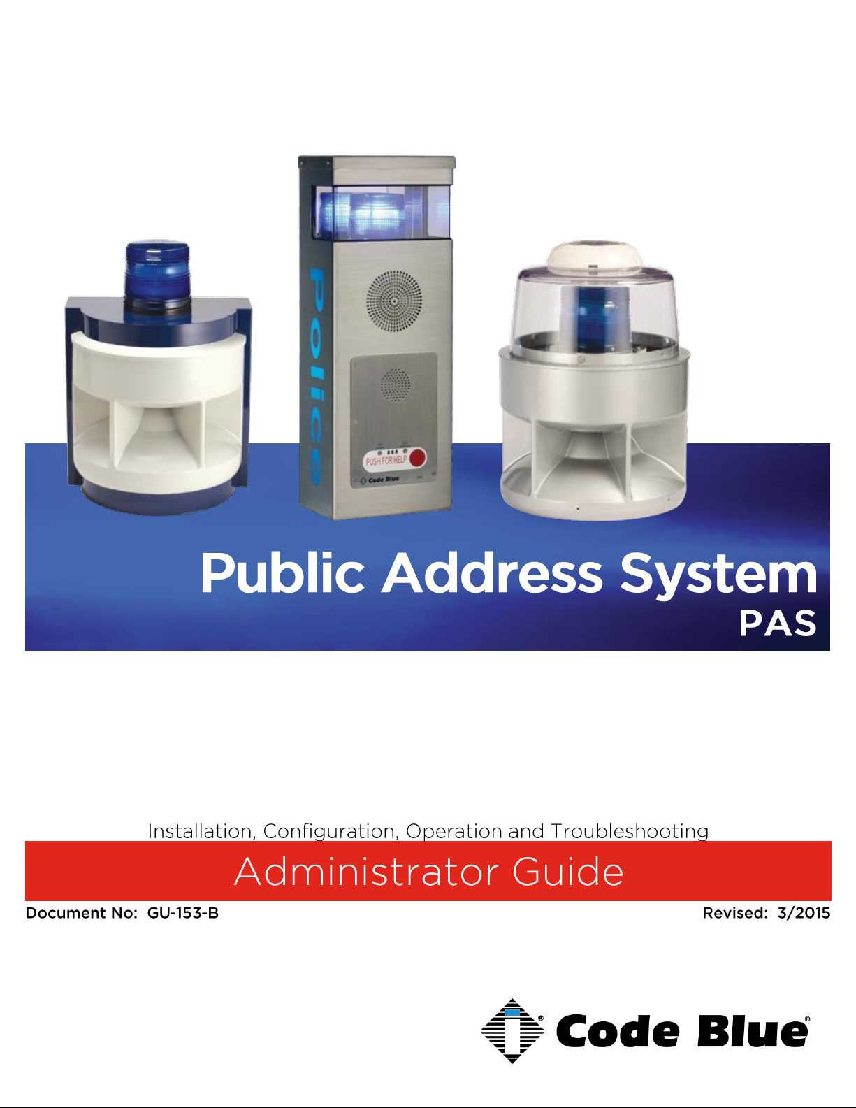
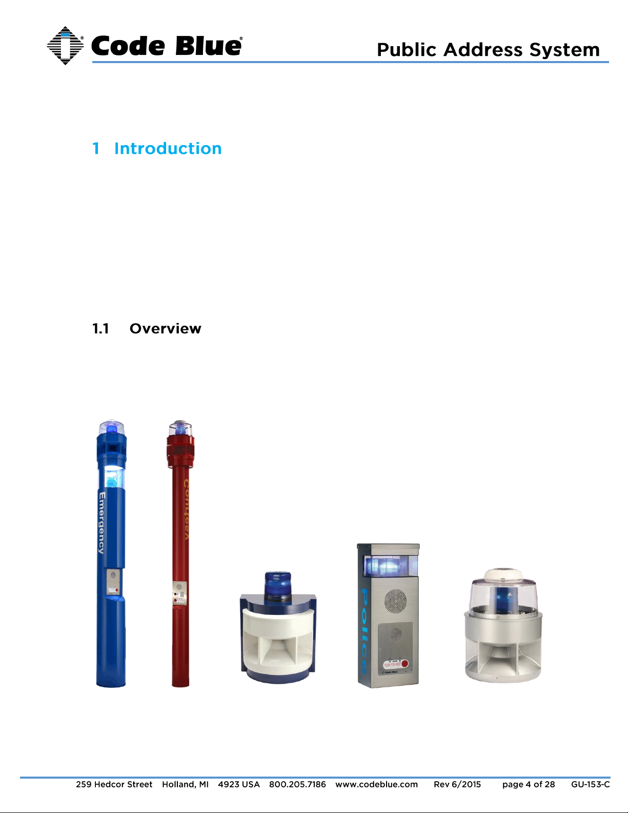
Thank you for choosing the Public Address option for your Code Blue application. Public
Address is a centralized amplifier-based system designed to provide voice paging and
broadcast alarm tones during emergencies. The system can transmit alarm tones and voice
messages in a reliable and safe manner from a central location to all or selected areas of the
facility via loudspeakers. The entire operational area can be divided into one or more zones,
which can be accessed independently either for announcements or alarm broadcasting.
Loudspeakers are installed in these zones. There are no limitations to the number of zones in a
system or number of loudspeakers in each zone. The system is designed to offer clear
reproduction of sound and intelligibility, even in high noise areas.
This manual contains all of the Code Blue PAS information needed on the CB 1 series with
Public Address, CB 5-s with Public Address, WM-180 Public Address System, CB 2-e with
Public Address and 360 PAS retrofit top. This manual contains a general overview of the Code
Blue PAS options and its application, installation and wiring.
CB 1-s w/ PAS CB 5-s w/ PAS WM 180 CB 2-e w/ Public Address 360 PAS Retrofit Top
Page 5

Administrator Guide
Code Blue ● ● ● ● ●
Large diameter towers; analog or IP
An excellent choice when instant mass notification of a geographic area is essential. The
unique six-speaker design delivers optimal audio source dispersion utilizing state-of-theart amplifiers and horn array.
Small diameter towers
Exclusively designed as an emergency communication system to deliver maximum
audio clarity and range to ensure notifications are accurately broadcast to your intended
audience.
Wall or pole mount; analog or IP
An excellent choice for parking decks, dorm entrances, hallways and public transit
centers where instant mass notification of a geographic area is essential.
PAS top kit for existing standard CB 1 series towers in the field to provide public address
capabilities.
The unique six-speaker design delivers optimal audio source dispersion utilizing state-of-
the-art amplifiers and horn array.
Wall or pole mount option remotely adds public address capabilities to new or existing
CB units.
By adding an analog or IP controller board, you enable the WM-180 to be directly man-
aged by Code Blue’s Blue Alert® MNS (Mass Notification System) software, granting the
user messaging options. The controller also monitors the amplifier and speaker for
various failures, which are reported to the appropriate maintenance personnel, and
allows the user to call a single WM-180 unit for a targeted message.
Page 6
Administrator Guide
Code Blue ● ● ● ● ●
This regulation covers the application, installation, location, performance, inspection, testing and
maintenance of fire alarm systems, supervising station alarm systems, public emergency alarm
reporting systems, fire warning equipment and emergency communications systems (ECS), and
their components.
This provides technical criteria for systems that implement mass notification in compliance with
the Department of Defense’s antiterrorism requirements. Implement national design standards
and recommendations for mass notification systems, as provided in NFPA 72, including Annex
E.
Code Blue recommends professional services before the order and installation of all PAS
products.
For survey information, please email customerservice@codeblue.com.
Ambient Noise Survey: Measures the sound energy flowing into, or outward from, a
specified area.
System Design Survey – Involves the placement, wiring and installation of PAS
equipment.
Complete Survey – Includes ambient noise and system design of PAS equipment.
Code Blue Technical Support
Email: tss@codeblue.com
Toll free: 800-205-7186, Opt. 3
Page 7
Administrator Guide
Code Blue ● ● ● ● ●
If the unit emits smoke or an unusual smell, water or other foreign materials enter the enclosure,
or the unit is dropped or the enclosure is damaged, power off immediately and contact Code
Blue Customer Service.
Email: customerservice@codeblue.com
Toll free: 800-205-7186, Opt. 2
Page 8
Administrator Guide
Code Blue ● ● ● ● ●
This section covers the following units:
CB 1 Series with Public Address, including the 360° PAS Retrofit Kit
CB 5-s with Public Address
CB 2-e with Public Address
WM-180°
The following models are covered in the installation instructions for CB 1 Series with Public
Address or the 360° PAS Retrofit Kit:
CB 1-e
CB 1-s
CB 1-d
Ladder – to reach the top of the unit.
Security bit – to secure the PAS top to the adapter ring.
6mm Allen wrench – to secure the PAS adapter ring to the top of the unit.
3/8” socket set - to mount the mounting plate containing the new toroid transformer.
3.1.2.1
Remove 120V AC power from the unit.
3.1.3
Remove the existing dome top assembly. Disconnect the red/black and 3.1.3.1
yellow/yellow wiring harnesses connected to the beacon/strobe mounted in the
dome top assembly.
Place the adapter ring on top of the bollard and tighten the three Allen set 3.1.3.2
screws to hold in place (see Figure 2 on Page 12).
Page 9
Administrator Guide
Code Blue ● ● ● ● ●
Install new toroid transformer.
NOTE: Skip this section if you ordered a CB 1 Series with Public
Address as a complete unit.
Remove lower access door on the CB 1 bollard. 3.1.4.1
Remove the existing 120V AC step down transformer. 3.1.4.2
Install toroid transformer with mounting plate using supplied hardware 3.1.4.3
(see Figure 1 on Page 10).
Connect incoming 120V AC wiring to the transformer using the junction 3.1.4.4
box on mounting plate. Refer to included wiring diagram for wiring terminations
(See Error! Reference source not found. on Page 19).
Run the supplied amplifier wiring harness, beacon/strobe power harness 3.1.4.5
(red/black), beacon/strobe auxiliary harness (yellow/yellow), 7 pin control cable and
RJ-11 audio cable to the top of the bollard. Connect the molded quick connector on
the red/black harness to the manifold connector on the transformer. Connect the
yellow/yellow harness, 7 pin control cable and RJ-11 to the phone board. Connect
the large white connector of the amplifier wiring harness to the wiring connector on
the transformer. Refer to the included wiring diagram for wiring terminations (See
Figure 1 on Page 10).
Page 10

Administrator Guide
Code Blue ● ● ● ● ●
Connect the red/black and yellow/yellow wiring harnesses to the red/black 3.1.5.1
and yellow/yellow wiring pigtails coming from the beacon/strobe.
Connect the 6 pin wiring harness, 7 pin control cable and RJ-11 audio 3.1.5.2
cable to the ports on the amplifier.
Set the PAS speaker unit on the adapter ring, lining up the screw holes at 3.1.5.3
the bottom of the unit. Secure the speaker unit with the provided security screws.
Figure 1
Page 11

Administrator Guide
Code Blue ● ● ● ● ●
Reapply power to the unit (see Error! Reference source not found. on 3.1.5.4
age 21).
Page 12

Administrator Guide
Code Blue ● ● ● ● ●
Ladder – to reach the top of the unit.
Security bit - to secure the PAS top to the adapter ring.
3/8” socket set - to secure the PAS adapter base to the top of the unit.
6mm Allen wrench - to secure the PAS adapter ring to the top of the PAS adapter
base.
Remove 120V AC power from the unit. 3.2.2.1
3.2.3
Remove existing beacon/strobe assembly. Disconnect the red/black and 3.2.3.1
yellow/yellow wiring harnesses connected to the beacon/strobe mounted on top of
the CB 5-s unit.
Place a foam gasket on the unit, then the adapter base on top of the 3.2.3.2
bollard and tighten the 3/8” bolts with washers to secure the adapter base to the set
screws to hold in place.
Place adapter ring on top of the adapter base and tighten the three Allen 3.2.3.3
set screws to hold in place (see Figure 2 on Page 12).
Connect the red/black and yellow/yellow wiring harnesses to the red/black 3.2.4.1
and yellow/yellow wiring pigtails coming from the beacon/strobe.
Connect the 6 pin wiring harness, 7 pin control cable and RJ-11 audio 3.2.4.2
cable to the ports on the amplifier.
Set the PAS speaker unit on the adapter ring, lining up the screw holes at 3.2.4.3
the bottom of the unit. Secure the speaker unit with the provided security screws.
Reapply power to the unit (See Error! Reference source not found. on 3.2.4.4
age 21).
Page 13

Administrator Guide
Code Blue ● ● ● ● ●
Figure 2
Page 14

Administrator Guide
Code Blue ● ● ● ● ●
Security bit - to remove phone to access mounting holes.
½-inch concrete bit – to drill holes in wall for the mounting anchors for mounting bolts.
9/16” socket set - to secure the housing to the wall with mounting bolts.
Electrical preparation: the unit may have supply wires run from either (a) 3.3.2.1
behind the unit through the wall, or (b) below the unit using an external conduit
through the bottom. Holes in the back and bottom have been provided for this
purpose (See Figure on Page 23).
Remove the top of the unit. 3.3.2.2
Mark the mounting holes. In order to comply with the Americans with 3.3.2.3
Disabilities Act (ADA), the speakerphone button(s) should be positioned between 34
and 48 inches from grade level. Consult an ADA specialist in your area to verify
local and federal guidelines.
Drill all marked holes. 3.3.2.4
Install the housing. Four anchors of appropriate size and type should be 3.3.2.5
used to fasten the housing to the wall (see Figure 3 on Page 14).
IMPORTANT: If wiring is being supplied from the back, ensure that
the conduit is aligned at this time.
Reattach the top. 3.3.2.6
Ground – The ground (green) wire should be stripped and fastened to the 3.3.3.1
supplied grounding lug.
24V AC supply – Using the proper crimping tool, attach a #8 fork to each 3.3.3.2
of the incoming power wires and fasten them to the terminal screws labeled “Line”
and “Neutral.”
120/240V AC supply – Using the proper crimping tool, attach a #8 fork to 3.3.3.3
each of the incoming power wires and fasten them to the correct terminals as
Page 15

Administrator Guide
Code Blue ● ● ● ● ●
labeled on the transformer. After completing the wire connections, install the
supplied terminal covers (see Figure on Page 23).
Have category 3 or higher 4 pair cable terminated to a RJ45 applying 3.3.4.1
TIA/EIA T568-B specifications.
Figure 3
Page 16

Administrator Guide
Code Blue ● ● ● ● ●
°
Ladder – to reach mounting height.
Security bit - to remove phone to access mounting holes.
½-inch concrete bit – to drill holes for the mounting anchors for the mounting bolts.
9/16” socket set - to secure the housing to the wall with mounting bolt.
Note: If unit does not include an IP or Analog controller board, then it
must be located near an IA4100 or IP5000 speakerphone for the 20foot supplied PAS cables to reach it.
*See included drawing for anchor bolt and conduit locations.
Supply 24V AC to Power Manifold (see Figure on Page 22). 3.5.1.1
Supply phone line to phone port if the unit has an analog controller board, 3.5.1.2
or Ethernet IP connection to LAN port if it has an IP controller board.
Reference IA4100 Admin and User Guide for analog controller board 3.5.1.3
programming.
Reference IP5000 Admin and User Guide for IP controller board 3.5.1.4
programming.
Code Blue guides are located at codeblue.com > support > downloads. 3.5.1.5
Supply 24V AC to Power Manifold. 3.6.1.1
See attached wiring diagram for connecting the PAS Audio Cable and 3.6.1.2
PAS Control Cable to the nearby IA4100 or IP5000 speakerphone.
Reference IA4100 Admin and User Guide for analog controller board 3.6.1.3
programming.
Page 17

Administrator Guide
Code Blue ● ● ● ● ●
Reference IP5000 Admin and User Guide for IP controller board 3.6.1.4
programming.
Code Blue guides are located at codeblue.com > support > downloads. 3.6.1.5
Figure 4
Page 18

Administrator Guide
Code Blue ● ● ● ● ●
Designed specifically for schools, hospitals, corporate and municipal campuses looking for an
efficient way to detect and respond, Blue Alert MNS (Mass Notification System) fills a need in
the marketplace for an incident response solution that is both comprehensive and costeffective. Blue Alert MNS provides emergency notifications over audio, visual and messaging
platforms at the touch of a button. The result is a sophisticated software solution that quickly
informs and directs people in emergency situations. Blue Alert MNS is available in two
editions, Audio/Visual and Messaging, or together in the Blue Alert MNS Professional
Package.
Blue Alert EMS (Event Management System) handles all incoming emergency and nonemergency events with an easy to use Graphical User Interface (GUI). Effectively utilize EMS
for remote operation of Code Blue emergency communication devices. Open gates and AED
access doors, turn LED beacon/strobe lights on or off, transfer calls to the Public Address
System to make area-wide announcements and incorporate other ancillary devices and
applications. Have a camera connected to your Code Blue unit or one mounted nearby?
Simply integrate EMS with your CCTV system for instant video when the units are activated.
Blue Alert EMS utilizes an advanced API for efficient integration with third party applications.
®
®
ToolVox UPD (Unit Programming & Diagnostics) software provides a user-friendly, web-based
GUI (Graphical User Interface) for the administration of all Code Blue units.
Unit Programming, UPD’s unique phone management feature, allows the user to easily
establish the functionality desired on one phone and copy all settings to additional units as
needed. In addition, audio files can be created at a PC and stored on the server. Different
messages can then be uploaded to each phone or the same audio file can be used on
multiple phones, eliminating the need to call each phone individually and re-record messages.
Once settings are complete, simply “Click to Program,” or select assorted units and choose
“Program All Units” to apply operational parameters.
The Diagnostic section of the software package is capable of testing all on-site Code Blue
units for functionality at any specified time daily, weekly or on a specified day and time. This
flexibility tailors testing at predetermined intervals to confirm the phones are working 24/7.
®
Page 19

Administrator Guide
Code Blue ● ● ● ● ●
Immediate fault reporting via multiple email addresses guarantees minimum response time to
any operational issues. Route an email to an SMS server and your on-call technician receives
a text on their cell phone for immediate deployment, ensuring maximum up time of your units.
Page 20

Administrator Guide
Code Blue ● ● ● ● ●
Figure 5
Page 21

Administrator Guide
Code Blue ● ● ● ● ●
Controller wiring diagram
Figure 6
Page 22

Administrator Guide
Code Blue ● ● ● ● ●
Wiring Diagram
Figure 7
Page 23

Administrator Guide
Code Blue ● ● ● ● ●
Figure 8
Page 24

Administrator Guide
Code Blue ● ● ● ● ●
Figure 9
Page 25

Administrator Guide
Code Blue ● ● ● ● ●
Figure 10
Page 26

Administrator Guide
Code Blue ● ● ● ● ●
Please contact Code Blue Technical Support if you do not see your issue below.
7.1.1.1
Try a new test call.
Remove the control cable from the amp. This will turn the amp on at all times.
Test power from the transformer to the amp. 7.1.1.2
Check the 5 amp slow blow inline fuse between the transformer and 5-finger 7.1.2.1
manifold.
Check power connector at the 5 finger manifold and the red/black power wire 7.1.2.2
from the strobe.
Short the yellow relay wires from the strobe to test strobe functionality. If the 7.1.2.3
strobe flashes, check programming in the IA4100/IP5000 speakerphone.
For CB 1 or 5 units, verify that you have 120V AC to the transformer. 7.1.3.1
For CB 2-e units, verify that you have either Hi-Voltage to the power brick or 24V 7.1.3.2
AC to the unit if low voltage only.
For WM-180° units, verify you have 24V AC to the unit 7.1.3.3
First, adjust the volume in the IA4100/IP5000 programming. On the IA4100, the 7.1.4.1
in-call command for increasing the volume is 28. To decrease the volume, the in-call
command is 29. On the IP5000, the Public Address Gain can be changed under hardware
settings.
The input gain also can be adjusted manually on the amplifier using the input gain 7.1.4.2
dial.
Page 27

Administrator Guide
Code Blue ● ● ● ● ●
For advanced trouble shooting, please email techsupport@codeblue.com or call 7.1.5.1
800-205-7186, Opt. 3.
Page 28

Administrator Guide
Code Blue ● ● ● ● ●
Part Number
Part Description
Notes
40010
Amp Assembly
Contains amp, toroid transformer and wire
harness
40007
Dome Top Assembly
Contains dome top and active vent
40159
Strobe
24V combination blue beacon/strobe
40101
5-Finger Manifold
Contains manifold and 5 amp fuse
Part Number
Part Description
Notes
40009
Amp Assembly
Contains amp and amp harness
40159
Strobe
24V combination blue beacon/strobe
40101
5-Finger Manifold
Contains manifold and 5 amp fuse
Part Number
Part Description
Notes
40009
Amp Assembly
Contains amp and amp harness, if needed
40101
5-Finger Manifold
Contains manifold and 5 amp fuse
°
 Loading...