

Page 1
INSTALLATION
& OPERATION
MANUAL
MODEL 3750
WARNING
Sirens produce loud sounds that may damage hearing
• Wear hearing protection when testing
• Use siren only for emergency response
• Roll up windows when siren is operating
• Avoid exposure to the siren sound outside of vehicle
IMPORTANT:
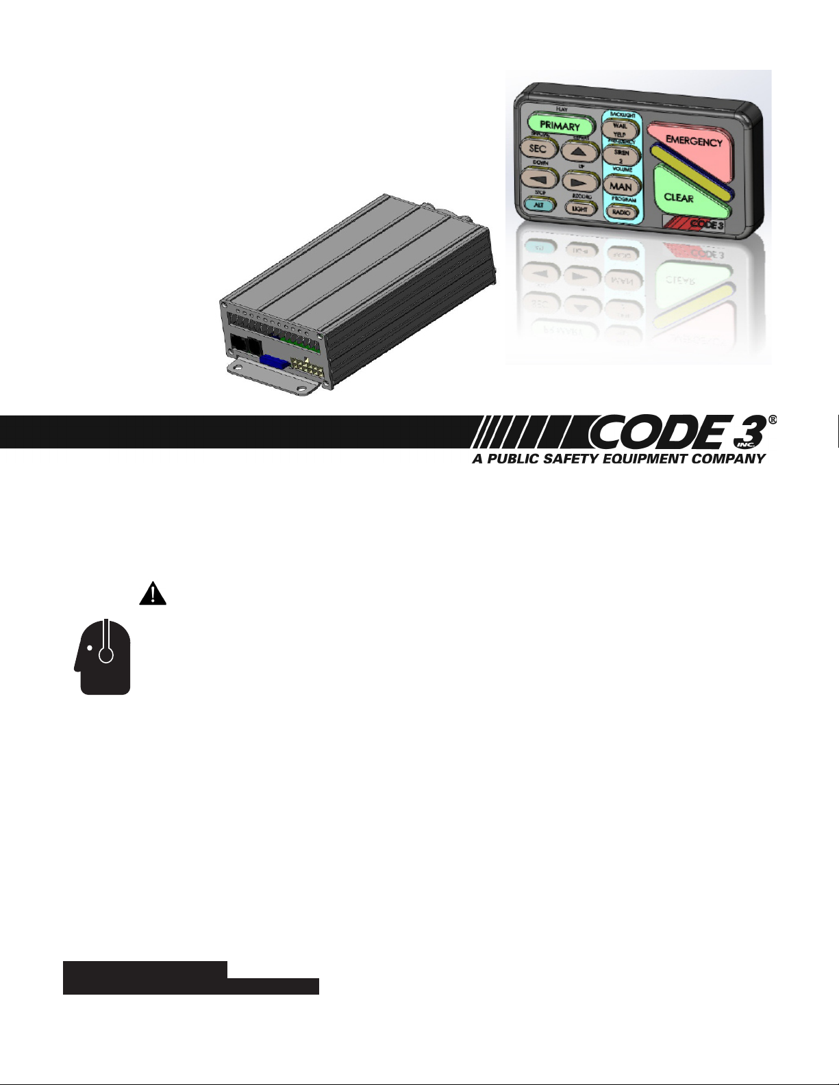
SPRINTER Remote Siren System
with Hand-Held Controller
Contents:
Introduction 2
Standard Features 3
Unpacking & Pre-Installation 3
Installation & Mounting 3
Connections, Fusing & Wire Diagram 4-6
Controller functions 7
Siren Peripherals Diagram 8
Main PCB Diagram and Fuse Locations 9
Public Address System 10
Customizing Control Head 11
Programming Capabilities 12-16
Troubleshooting 16
Specications and Maintenance 17
Installation Note Pages 18-19
Warranty 20
Read all instruction and warnings before installing and using.
INSTALLER: This manual must be delivered to the end user of this equipment.
1
Page 2

Introduction
The SPRINTER uses an easily concealable remote hand held controller coupled to an electronic siren, all designed
to meet the needs of emergency vehicles. This siren provides a compact control head that can virtually be mounted
anywhere in the vehicle along with full 100Watt signal output providing both SAE J1849 and CA Title 13 Compliance.
The purpose of this document is to aid in the setup and installation of the SPRINTER, and to provide instructions for its
proper operation.
Sirens are an integral part of an effective audio/visual emergency warning system. However,
sirens are only short range secondary warning devices. The use of a siren does not insure
that all drivers can or will observe or react to an emergency warning signal, particularly at long
distances or when either vehicle is traveling at a high rate of speed. Sirens should only be used
in a combination with effective warning lights and never relied upon as a sole warning signal.
Never take the right of way for granted. It is your responsibility to be sure you can proceed safely
SIREN PRODUCTS
before entering an intersection driving against trafc, or responding at a high rate of speed.
The effectiveness of this warning device is highly dependent upon correct mounting and wiring.
Read and follow the manufacturer’s instructions before installing this device. The vehicle operator
should check the equipment daily to insure that all features of the device operate correctly.
To be effective, sirens must produce high sound levels that potentially can inict hearing damage.
Installers should be warned to wear hearing protection, clear bystanders from the area and not
to operate the siren indoors during testing. Vehicle operators and occupants should assess their
exposure to siren noise and determine what steps, such as consultation with professionals or
use of hearing protection should be implemented to protect their hearing.
This equipment is intended for use by authorized personnel only. It is the user’s responsibility
to understand and obey all laws regarding emergency warning devices. The user should check
all applicable city, state and federal laws and regulations. Code 3, Inc., assumes no liability for
any loss resulting from the use of this warning device.
Proper installation is vital to the performance of the siren and the safe operation of the
emergency vehicle. It is important to recognize that the operator of the emergency vehicle is
under psychological and physiological stress caused by the emergency situation. The siren
system should be installed in such a manner as to: A) Not reduce the acoustical performance of
the system, B) Limit as much as practical the noise level in the passenger compartment of the
vehicle, C) Place the controls within convenient reach of the operator so that he can operate
the system without losing eye contact with the roadway.
Emergency warning devices often require high electrical voltages and/or currents. Properly
protect and use caution around live electrical connections. Grounding or shorting of electrical
connections can cause high current arcing, which can cause personal injury and/or severe
vehicle damage, including re.
PROPER INSTALLATION COMBINED WITH OPERATOR TRAINING IN THE PROPER
USE OF EMERGENCY WARNING DEVICES IS ESSENTIAL TO INSURE THE SAFETY OF
EMERGENCY PERSONNEL AND THE PUBLIC.
2
Page 3

Standard Features
The SPRINTER system offers the following features:
- Primary Tones: Wail, Yelp, Hi-Lo, Manual
- program selectable Siren tones including Air Horn
- Vehicle Light Control Buttons
- PA with Built-In Noise Cancelling Microphone with Integrated Volume Control
- Radio rebroadcast
- Park Light function
- Horn Ring Option
- Backlit Buttons with On/Off Intensity Change
- Pass protected volume and programming functions
- Programmable Siren Controls
- Programmable Light Controls
- Externally accessible 15A fuse
- Control Head with Extension Cable
Unpacking & Pre-Installation
After unpacking the siren, carefully inspect the unit and associated parts for any damage that may have been caused
in transit. Report any damage to the carrier immediately.
Parts included in the box:
- Siren (amplier)
- Hand-Held Controller
- Microphone
- Control Head Extension Cable
- Connection Parts Bag
- Wire Harness
- Installation / Operator Manual
Installation & Mounting
The hand-held controller may be mounted in various locations in the vehicle: below the dash, on the tunnel, etc. Ease
of operation and convenience to the operator should be the prime consideration when mounting the siren and controls.
The amplier may be mounted at an appropriate location within the vehicle, and the extension cable must be used to
couple the hand-held controller to the amplier. Caution: Do not plug control head unit into microphone socket on
Amplier. Use of the extension cable will assure the control head is plugged in correctly.
All devices should be mounted in accordance with the manufacturer's instructions and securely
fastened to vehicle elements of sufcient strength to withstand the forces applied to the device.
Ease of operation and convenience to the operator should be the prime consideration when
mounting the siren and controls. Adjust the mounting angle to allow maximum operator visibility.
Do not mount the Hand-Held Controller in a location that will obstruct the drivers view. Mount the
Hand-Held Controller mounting base in a convenient location to allow the operator easy access.
Devices should be mounted only in locations that conform to their SAE identication code as
described in SAE Standard J1849. For example, electronics designed for interior mounting
should not be placed under hood, etc. Controls should be placed within convenient reach* of
the driver or if intended for two person operation the driver and/or passenger. In some vehicles,
multiple control switches and/or using methods such as “horn ring transfer” which utilizes the
vehicle horn switch to toggle between siren tones may be necessary for convenient operation
from two positions.
*Convenient reach is dened as the ability of the operator of the siren system to manipulate the
controls from their normal driving/riding position without excessive movement away from the seat
back or loss of eye contact with the roadway.
Page 4

The SPRINTER amplier is not waterproof. It must be mounted in a location that is sheltered from rain, snow, standing
water, etc. It must also be installed in an adequately ventilated area. Do not install near heater ducts or under the vehicle’s
hood. Using the mounting holes on the amplier as a template, scribe four drill position marks at the mounting locations. Be
sure that both sides of the mounting surface are clear of parts that may be damaged. The siren accessory kit with mount-
ing hardware supplied provides the user with a choice of mounting hardware. Secure the amplier to the mounting surface,
using the mounting hardware.
Connection between the hand-held controller and the SPRINTER amplier box is identied by the amplier label.
Note: The microphone and control head connectors are different and must not be plugged into the wrong socket.
Use of the extension cable will assure the control head is plugged in correctly.
Larger wires and tight connections will provide longer service life for components. For high current
wires it is highly recommended that terminal blocks or soldered connections be used with shrink
tubing to protect the connections. Do not use insulation displacement connections (e.g. 3M) Scotch
lock type connectors. Route wiring using grommets and sealant when passing through compartment
walls. Minimize the number of splices to reduce voltage drop. High ambient temperatures (e.g.
under hood) will signicantly reduce the current carrying capacity of wires, fuses, and circuit breakers.
Use “SXL” type wire in engine compartment.
All wiring should conform to the minimum wire size and other recommendations of the manufacturer
and be protected from moving parts and hot surfaces. Looms, grommets, cable ties, and similar
installation hardware should be used to anchor and protect all wiring.
Fuses or circuit breakers should be located as close to the power takeoff points as possible and
properly sized to protect the wiring and devices. Particular attention should be paid to the location
and method of making electrical connections and splices to protect these points from corrosion
and loss of conductivity. Ground (Earth) terminations should only be made to substantial chassis
components, preferably directly to the vehicle battery.
The user should install a circuit breaker sized to approximately 125% of the maximum Amp capacity
in the supply line to protect against short circuits. For example, a 30 Amp circuit breaker should carry
a maximum of 24 Amps.
DO NOT USE 1/4” DIAMETER GLASS FUSES AS THEY ARE NOT SUITABLE FOR CONTINUOUS
DUTY IN SIZES ABOVE 15 AMPS. Circuit breakers are very sensitive to high temperatures and will
“false trip” when mounted in hot environments or operated close to their capacity.
Connections
Reference Figure 1 – Wiring Diagram
Disconnect the cable on the negative end of the battery before performing installation. Do not connect the system to 1.
vehicle battery until all other electrical connections are made and mounting of all components is complete. Verify the
polarities of the cable and ensure that no short circuits exist before connecting to the battery terminals. If routing the
extension cable requires drilling a hole in sheet metal or other material, drill a 5/8″ hole in the material and install a 5/8″
grommet (not supplied) to protect the cable.
Attach the handheld controller to the amplier by inserting the connector on the end of the cord into the mating port on 2.
the amplier. If the amplier is remotely mounted, use the included extension cord and extension adaptor.
4
Page 5
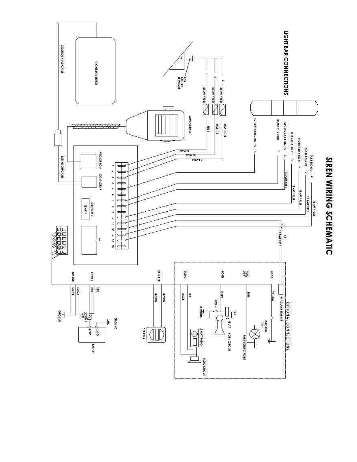
Figure 1 - Wiring Diagram
3. To install the positive and negative power wires, strip 1/4” of insulation from the end of the wires, and install the blade
connectors onto the ends of the appropriate wires. The “+12V” positions may be connected either directly to a +12V
source (such as a battery), or through a switch (such as an ignition switch). (See proper fusing requirements on page
6 prior to making any wire connections to battery or ignition switch)
5
Page 6

4. The unit is supplied with a twelve-position, pluggable connector (white color) for connections to the speaker and other
selected optional connections such as hood,grill, radio, horn ring and parklight . Main light bar connections are made
at the blade connections in the back of the amplier unit and are labelled with identication to coincide with the control
head.
5. Speaker – the siren is designed to operate with one 11-ohm impedance speaker (100W). Speakers are not included as
part of the siren. Any 11-ohm 100W speaker for use with emergency vehicle may be considered to use.
CONNECTION OF A 58 WATT SPEAKER TO THE SPKR TERMINAL WILL CAUSE THE SPEAKER
TO BURN OUT, AND WILL VOID THE SPEAKER WARRANTY!
6. To install the light bar power wires, strip approximately 1/4″ of insulation from the end of the lights wires. Install the blade
wire connectors onto the wire ends and connect the appropriate wires to the terminals on the amplier housing to coincide with the light bar wire function identication. Keep in mind that terminals 8, and 10-14 have a 15 amp maximum
current each. Power wires on pins 1,2 and 3 have a max. current of 20A each.
External 25A fuse is required on each of the 3 individual +12V power wires on pins 1,2 and 3 at the battery feed.
(Pin 4 is not used)
Pin 5 max current of 20A.
Pin 7 max current 20A.
Pin 8 internally fused for 15A
(Pin 9 not used)
Pins 10 - 14 are all internally fused for 15A each. (See gure 5, page 9 for fuse location)
- left alley ( Pin 10),
- right alley ( Pin 11),
- sign light ( Pin 12),
- headlight asher ( Pin 13),
- take down lights ( Pin 14).
(Pin 15 not used)
7. If a fuse is installed, it should be sized for the actual load of the lighting used and located as close to the battery positive
as possible.
8. Ensure that there are no loose wire strands or other bare wire that may cause a short circuit. All wires must be protected
from any sharp edged that could eventually cut through the insulation. Also use an ohmmeter to verify that a short circuit
does not exist between the positive (+) leads and the vehicles chassis.
Any electronic device my create or be affected by electromagnetic interference. After installation
of any electronic device, operate all equipment simultaneously to insure that operation is free of
interference.
6
Page 7

IMPORTANT WARNINGS TO USERS OF SIRENS: “Wail” and “Yelp” tones are in some cases (such
as the state of California) the only recognized siren tones for calling for the right of way. Ancillary
tones such as “Air Horn”, “Hi-Lo”, “Hyper Yelp”, and “Hyper Lo” in some cases do not provide as high
a sound pressure level. It is recommended that these tones be used in a secondary mode to alert
motorists to the presence of multiple emergency vehicles or to the momentary shift from the primary
tone as an indication of the imminent presence of any emergency vehicle.
This siren system is CA T13 compliant when congured properly. Limitation of siren tones available to the end user are
password protected to insure CA T13 compliance.
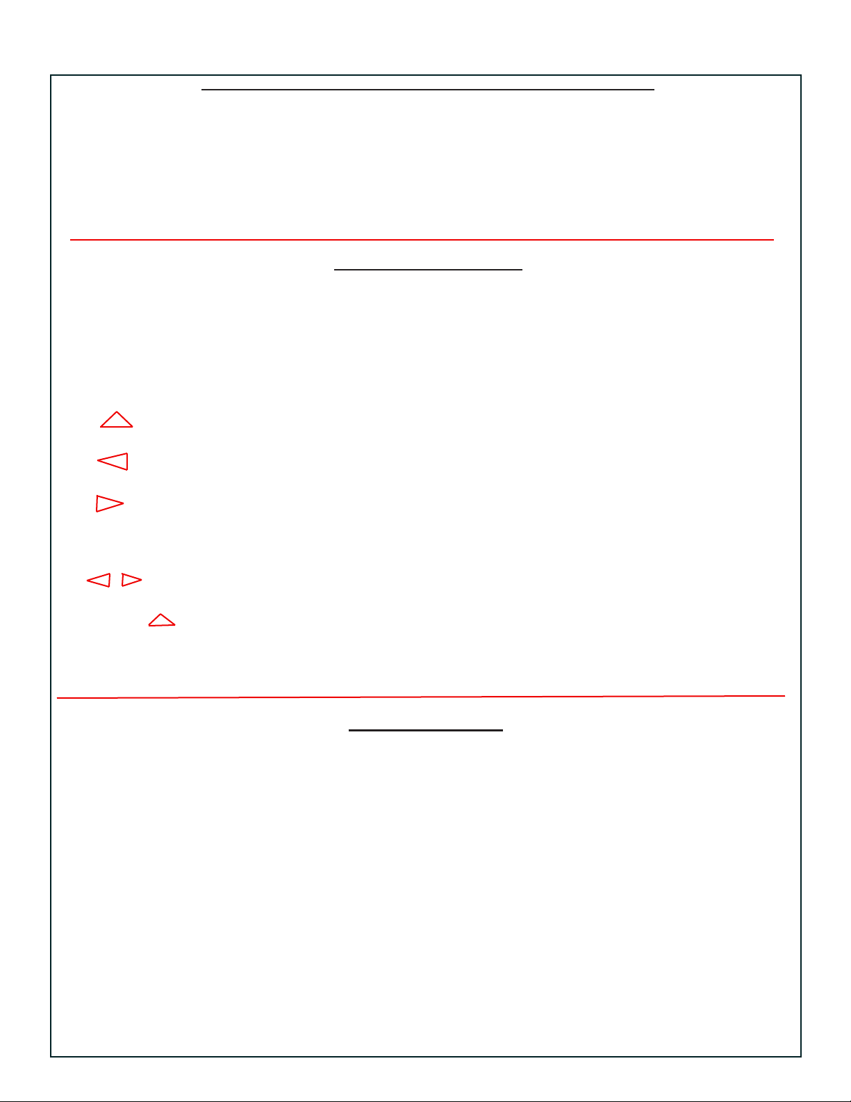
(Lighting Control keys are found on the light grey pad. Auditory Control keys are found on the blue pad in the center of the Controller.)
Primary light controls (play recorded message)
Take Down lights (recorded message repeat)
Hi Lo siren #2 (ash rate program)
Standard Wail and Yelp siren tones (back light program)
Enable quick selection of lights and siren
Secondary
lights
Bargraph
display
left alley
(vol up prgrm)
program select Clear all selections
and record stop
sign light , (message record) Manual siren key (siren volume select prgm)
right alley
(vol down prgrm)
Radio rebroadcast - PA (program function key)
Figure 2 - Controller Functions
7
Page 8
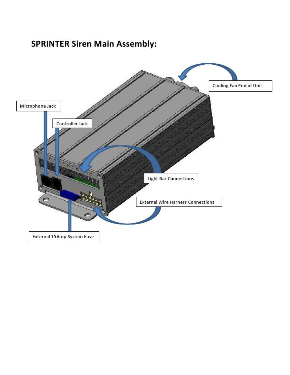
Figure 3.
8
Page 9

Figure 4.
Figure 5.
9
Page 10
Hand Held Controller Label Designations and Functions:
Item: Label: Operation: Activation: Description:
Bargraph located between the
Display CLEAR and EMERGENCY lighted postion along displays a series of
keys on the controller bar lights in 6 positions
along bar
LIGHTING CONTROLS:
Item: Label: Operation: Activation: Description:
1. PRIMARY Turns on/off primary front directional and corner
warning lights
2. SEC Turns on/off secondary rear directional
warning lights
3. Turns on/off takedown lights
4. Turns on/off left alley light
5. Turns on/off right alley light
6. LIGHT Turns on/off sign light
7. Turns on/off headlamp asher (both keys pressed together)
8. SEC Turns on/off intersection lights (both keys pressed together)
9. CLEAR Turns off all warning lights
and sirens
SIREN CONTROLS:
10. WAIL YELP Turns on/off Wail-Yelp Siren (default: std. Wail-Yelp)
11. SIREN 2 Turns on/off 2nd siren (default: Hi-Lo)
12. MAN Turns on manual siren while
button is depressed (default: Manual Wail) Returns to previous
siren when
released.
13. EMERGENCY Activates pre-set light and Press EMERGENCY
siren warnings button once.
(OR) Pressing CLEAR
Alternates yelp/wail if siren Press EMERGENCY will turn off the
is currently activated button additional times. EMERGENCY
function including
all lights and sirens.
10
Page 11

PUBLIC ADDRESS SYSTEM:
Item: Label: Operation: Activation: Description:
14. RADIO Turns on/off radio repeat function
(will switch audio from vehicle (Pressing CLEAR
radio through to the main speaker. will turn off the
Adjust volume using the vehicle radio repeat
radio.) function.)
15. MICROPHONE PTT (Push To Talk) ready for (Will suspend any
immediate use siren operation and
will switch the
microphone through
the main speaker.)
(Use volume on the
adjustment on micro phone.)
Using Voice Recording:
16. CLEAR, ALT, RECORD
To record a message for playback (bar graph will display (2 second delay to
time in 10 sec. increments begin recording once
60 seconds are available) Mic button is pressed)
17. ALT, PLAY To play back a recorded message Starts voice message play
back.
18. CLEAR CLEAR stops voice message
(OR) playback
ALT,ALT ALT, ALT stops voice playback
without turning off any lights
that may be activated
19. ALT, REPEAT Starts voice playback in a
constant repeat mode.
20. CLEAR Stops continuous play back
(OR) and turns off any lights selected
ALT,ALT ALT, ALT stops voice playback
without turning off any lights
that may be activated
11
Page 12

CUSTOMIZATION OF THE CONTROL HEAD:
(Pass Code must be entered to make certain program adjustments,
Contact your dealer to obtain Pass Code if needed)
Item: Label: Operation: Activation: Description:
BACKLIGHTING ADJUSTMENT:
21. ALT, BACKLIGHT Adjusts brightness of keys Up & Down keys will ash Adjust brightness by
on controller key pad. pressing Up or Down
keys, when nished
press ALT to save
settings or to exit
without saving press
CLEAR.
SIREN VOLUME ADJUSTMENT:
(Pass code protected adjustment)
22. ALT, VOLUME Adjusts volume of siren Up & Down keys will ash Adjust volume by
to t situations pressing Up or Down
keys, when nished
press ALT to save
settings or to exit
without saving press
CLEAR.
LIGHT FLASH RATE ADJUSTMENT:
(WHERE APPLICABLE)
23. ALT, FREQUENCY Used to adjust ashing rate of lights when a Adjust ash rate by
general timer is used to control ashing rate pressing Up or Down
of lights. keys, when nished
press ALT to save
NOTE: ALT, PROGRAM nust rst be settings or to exit
changed to use a different function than without saving press
toggle. CLEAR.
12
Page 13

PROGRAMMING CAPABILITIES:
(Pass Code must be entered to make certain program adjustments,
Contact your dealer to obtain Pass Code if needed)
Item: Label: Operation: Activation: Description:
FEATURES THAT ARE PROGRAMMABLE:
1. Setting light switch functions
2. Selecting different siren Wail/Yelp tones
3. Selecting different 2nd siren tones
4. Selecting different Manual siren tones
5. Programming the EMERGENCY key functions
(Normally, the programming mode is Pass Code protected,
Contact your dealer to obtain Pass Code if needed)
ALT, PROGRAM Enters the program mode ALT & PROGRAM
of the control head. keys will lighted (If the Passcode is
not entered within
5 seconds, the unit
will return to the
idle condition)
Once the 4 digit
code is entered, the
controller will beep
and the ALT &
PROGRAM keys
will be lighted.
(Pressing CLEAR while in the programming mode
will exit programming without saving any
changes made during the programming session.)
PROGRAMMING STEP #1:
LIGHT SWITCH FUNCTIONS:
Beginning programming mode, the following keys will be illuminated:
, , ,PRIMARY, SEC, LIGHT Indicating Step #1 in Each key will light
programming mode. according to its
current program
state of operation.
STATES OF OPERATION:
#1 Alternate: LED on #3 Timed: LED fast ashing (0.25 sec.) If not lit, it could be
#2 Flashing: LED ashing (0.5 sec.) #4 Momentary: LED off set to momentary
(pressing a key will cycle it through the different states of operation) mode.
13
Page 14

ALT Will advance the programming mode to next step.
PROGRAMMING STEP #2:
SELECTION OF DIFFERENT WAIL SIREN TONES:
the following keys will be illuminated:
WAIL/YELP (will be illuminated) Indicating Step #2 in Bargraph will light
programming mode. according to its
current program
tone selected.
(Use Up & Down
keys to select one
of the choices. Bar
graph will indicate
ALT Will advance the programming mode to next step. choice of selection)
PROGRAMMING STEP #3:
SELECTION OF DIFFERENT YELP SIREN TONES:
the following keys will be illuminated:
WAIL/YELP (will be ashing) Indicating Step #3 in Bargraph will light
programming mode. according to its
current program
tone selected.
(Use Up & Down
keys to select one
of the choices. Bar
graph will indicate
ALT Will advance the programming mode to next step. choice of selection)
PROGRAMMING STEP #4:
SELECTION OF DIFFERENT 2nd SIREN TONES:
the following keys will be illuminated:
SIREN 2 (will be illuminated ) Indicating Step #4 in Bargraph will light
programming mode. according to its
current program
tone selected.
(Use Up & Down
keys to select one
of the choices. Bar
graph will indicate
ALT Will advance the programming mode to next step. choice of selection)
14
Page 15

PROGRAMMING STEP #5:
SELECTION OF DIFFERENT MANUAL SIREN TONES:
the following keys will be illuminated:
MAN (will be illuminated ) Indicating Step #5 in Bargraph will light
programming mode. according to its
current program
tone selected.
(Use Up & Down
keys to select one
of the choices. Bar
graph will indicate
ALT Will advance the programming mode to next step. choice of selection)
PROGRAMMING STEP #6:
ENABLES PROGRAMMING OF THE LIGHT key:
the following keys will be illuminated:
RADIO (will be illuminated Indicating Step #6 in Pressing any key
along with other any programming mode. while in the LIGHT
other keys programmed programming mode
into the light list.) will include that key
function in the list
of functions for the
EMERGENCY key.
Headlight Flasher:
If the vehicle is equiped with a headlight asher, pressing both the left and right arrow keys
at the same time will enable this function when the EMERGENCY key is selected and will
illuminate the ALT key to indicate such.
Intersection Lights:
If the vehicle is equipped with intersection lights, pressing both the SEC & TAKEDOWN keys
at the same time will enable this function when the EMERGENCY key is selected.
(No indication is displayed for this function.)
ALT Will advance the programming mode to next step.
15
Page 16

PROGRAMMING STEP #7:
ENABLES PROGRAMMING OF THE EMERGENCY key:
the following keys will be illuminated:
EMERGENCY (will be illuminated Indicating Step #7 in Pressing any key
along with other any programming mode. in EMERGENCY
other keys programmed programming mode
into the light list.) will include that key
function in the list
of functions for the
EMERGENCY key.
Headlight Flasher:
If the vehicle is equipped with a headlight asher, pressing both the left and right arrow keys
at the same time will enable this function when the EMERGENCY key is selected and will
illuminate the ALT key to indicate such.
Intersection Lights:
If the vehicle is equipped with intersection lights, pressing both the SEC & TAKEDOWN keys
at the same time will enable this function when the EMERGENCY key is selected.
(No indication is displayed for this function.)
Changing the initial condition of the SIREN tone from WAIL to YELP
Can be done by pressing the key to the following conditions:
WAIL/YELP key; Illumination condition: OFF Indicates: Siren tone off
Illumination condition: ON Indicates: setting to WAIL tone
Illumination condition: FLASHING Indicates: setting to YELP tone
When nished
press ALT to save
settings or to exit
without saving press
CLEAR.
TROUBLE SHOOTING:
PROBLEM PROBABLE CAUSE REMEDY
No siren output shorted speaker or speaker wires check connections and wire ways
Fuse Blows amplier wires reversed polarity check polarity of wire connections
Siren tone volume low or garbled low voltage to siren amplier, high
resistance in wiring/ defective spkr.
High rate of speaker failures high voltage to siren, 58 W speaker
connected-(58 W spkr not allowed)
Backlight will not light or adjust parklight input must have +12V for
backlight to function on controller
Auxiliary lights do not operate IE:
alley, TD , sign board, headlight
ashers
short ciruit of wiring for light in
question, internal fuse blown in
amplier
check wiring for bad connections,
check spkr wiring, replace speaker
check vehicle charging system,
install 100W speaker in system
engage parklights on vehicle if
wired into system. or apply +12V.
to parklight circuit input on Amp.
check wiring and connections to
lights in question, check and re-
place fuse in amplier circuit
16
Page 17

SPECIFICATIONS AND MAINTENANCE:
Specications:
Siren Section
Input Voltage 10-15VDC (negative ground)
Input Current 10 Amps @ 13.6VDC
Output Voltage Maximum 100W @ 12VDC
Operating Temperature -30 °C to +65 °C
Dimensions (HWL):
Handheld controller 0.65”X 2.0”X3.7”
Amplier 2.0″X3.6″X7.6″
Weight – Siren (approx): 4.0 lbs
Weight – Controller (approx): 0.5 lbs
Base: Black powder coat painted aluminum extrusion
Mounting – Siren: 4-hole ange mounting on base
Mounting – Controller: (Not specied), (4 mounting holes provided on base)
Compliance: SAE J1849, California Title 13
Warranty: 5 years
Maintenance:
Your Code 3 siren has been designed to provide trouble free service. In case of difculty,
consult the Troubleshooting Guide of this manual. Also check for shorted or open wires.
The primary cause of short circuits has been found to be wires passing through re walls,
roofs, etc. If further difculty persists, contact the factory for troubleshooting advice or
return instructions.
Public Safety Equipment, Inc. maintains a complete parts inventory and service facility
at the factory and will repair or replace (at the factory’s option) any unit found to be defective under normal use and in warranty. Any attempt to service a unit in warranty, by
anyone other than a factory-authorized technician, without the express written consent
of the factory, will void the warranty.
Units out of warranty can be repaired at the factory for a nominal charge on either a at
rate or parts and labor basis. Contact the factory for details and return instructions. Public Safety Equipment, Inc. is not liable for any incidental charges related to the repair or
replacement of a unit unless otherwise expressly agreed to in writing by the factory.
17
Page 18

Installation Notes:
18
Page 19

Installation Notes:
19
Page 20

WARRANTY
Code 3®, Inc.’s emergency devices are tested and found to be operational at the time of manufacture. Provided they are installed and
operated in accordance with manufacturer’s recommendations, Code 3®, Inc. guarantees all parts and components except the lamps to a period
of 1 year, LED Light head modules to a period of 5 years (unless otherwise expressed) from the date of purchase or delivery, whichever is later.
Units demonstrated to be defective within the warranty period will be repaired or replaced at the factory service center at no cost.
Use of lamp or other electrical load of a wattage higher than installed or recommended by the factory, or use of inappropriate or
inadequate wiring or circuit protection causes this warranty to become void. Failure or destruction of the product resulting from abuse or unusual
use and/or accidents is not covered by this warranty. Code 3®, Inc. shall in no way be liable for other damages including consequential, indirect
or special damages whether loss is due to negligence or breach of warranty.
CODE 3®, INC. MAKES NO OTHER EXPRESS OR IMPLIED WARRANTY INCLUDING, WITHOUT LIMITATION, WARRANTIES OF
FITNESS OR MERCHANTABILITY, WITH RESPECT TO THIS PRODUCT.
PRODUCT RETURNS
If a product must be returned for repair or replacement*, please contact our factory to obtain a Return Goods Authorization
Number (RGA number) before you ship the product to Code 3®, Inc. Write the RGA number clearly on the package near
the mailing label. Be sure you use sufcient packing materials to avoid damage to the product being returned while in
transit.
*Code 3®, Inc. reserves the right to repair or replace at its discretion. Code 3®, Inc. assumes no responsibility or liability for expenses incurred for the removal and /or reinstallation of products requiring service and/or repair.; nor for the packaging,
handling, and shipping: nor for the handling of products returned to sender after the service has been rendered.
Problems or Questions? Call The Technical Assistance HOTLINE - (314) 996-2800
Code 3, Inc.
www.code3pse.com
Code 3 is a registered trademark of
Code 3, Inc.
St. Louis, Missouri 63114-2029—USA
Ph. (314) 426-2700 Fax (314) 426-1337
Revision 1, 01/2013 - Instruction Book Part No. T56020.1 ©2012
10986 N. Warson Road
Code 3,® Inc., a subsidiary of
Public Safety Equipment, Inc.
Public Safety Equipment, Inc. Printed in USA
20
 Loading...