

Page 1
10986 N. Warson Road • St. Louis, MO 63114
314-426-2700 • www.code3esg.com
Page 2
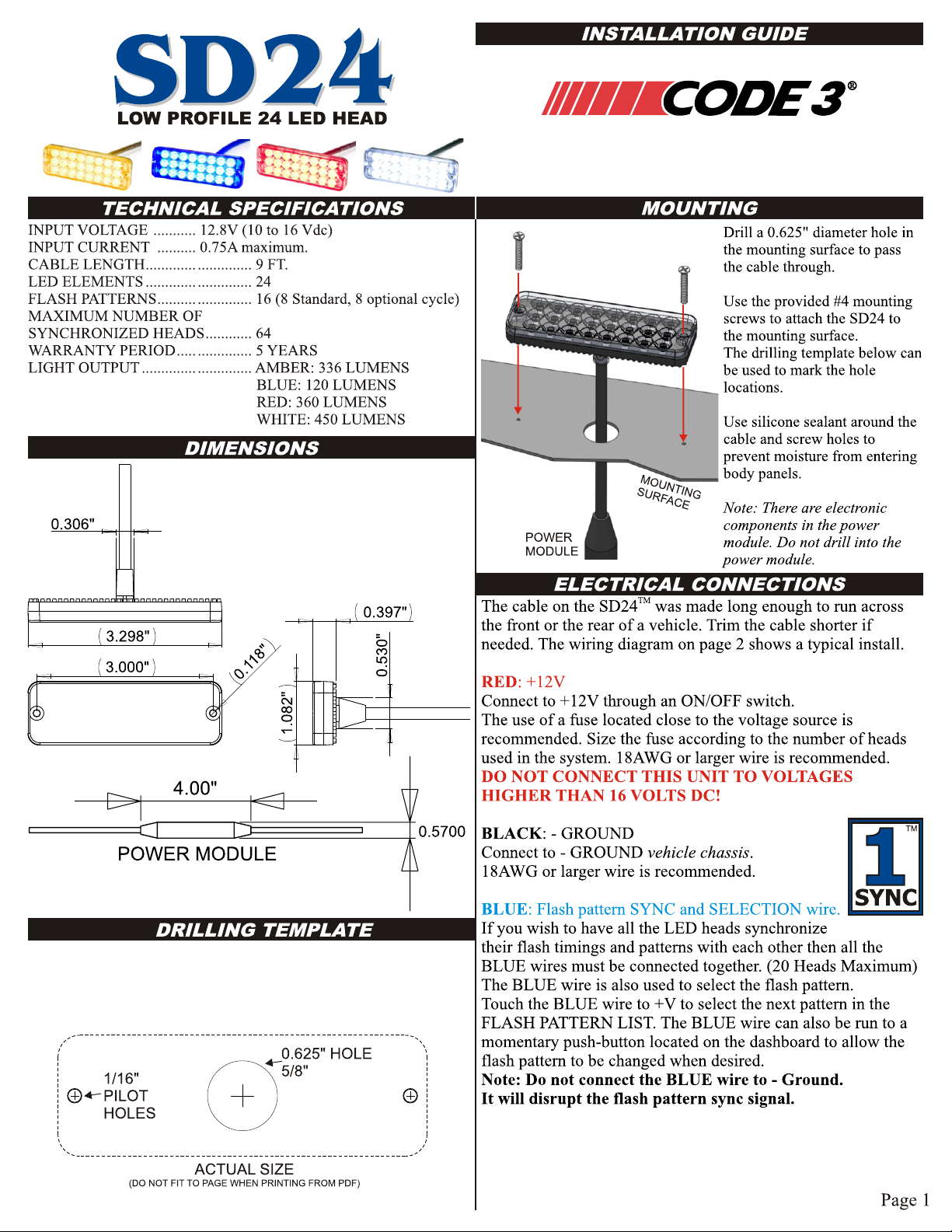
ELECTRICAL CONNECTIONS
YELLOW: Alternating / Simultaneous selection.
The BLUE wires of all SD24 heads must be connected together for
the alternating /simultaneous function to work.
Connect to either +V or GROUND (GND).
The YELLOW wire makes the head fire AT THE SAME TIME or
ALTERNATING with the other heads in the system.
Heads with YELLOW connected to +V fire at the same time.
Heads with YELLOW connected to GND fire at the same time.
Heads with YELLOW connected to +V will ALTERNATE with heads
that have YELLOW connected to GND.
The YELLOW wire has no function in STEADY ON mode.
The SD24 will also synchronize with any BULL LED or HIDEA-LED head. The wiring colors and functions are identical.
TM TM
TM
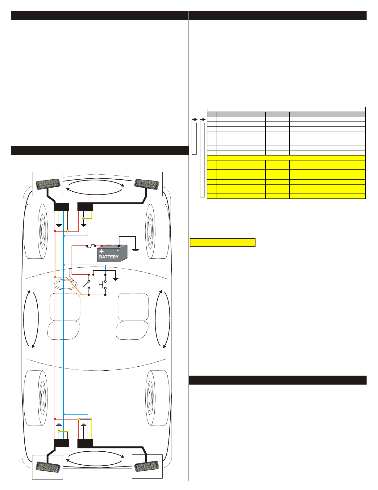
INSTALLATION OF 4 SD24 USING PATTERN SELECT
SWITCH PANEL (OPTIONAL) ON DASHBOARD.
YELLOW
TO +V
RED
BLACK
BLUE
TM
WIRING DIAGRAM
YELLOW
TM
ALTERNATE FLASHING
YELLOW
TO - GND
FLASH PATTERNS
POWER-UP RESET:
After installing the system it is best to do a POWER-UP RESET
the first time to ensure that all heads are in sync.
Touch wires to +V wire) while applying power.
Release wires. All heads will reset to Pattern #2.
BLUE
BLUE
If you have installed a pattern select pushbutton, press and hold
pattern select while turning power switch ON.
To select a flash pattern, touch to +V or press pattern
select switch to increment the flash pattern. The heads will
remember the selected pattern even if power is removed.
# Pattern: Frequency: Description:
1 Quad Flash 1.25 Hz 75 Quad Flashes Per Minute.
Double Flash
2
3 Triple Flash 1.53 Hz 92.3 Triple Flashes Per Minute.
DeciBlast
4
Single Flash
5
6 Mega Flash 1.90 Hz 114 Single Flashes Per Minute.
Triple+Burst
7
STANDARD ONLY
8 Steady On Steady On.
Cycle All
9
10 Double-Triple+Burst 2 Double, 2 Triple+Burst cycle.
Cycle Classic
11
STANDARD + CYCLE
12 Quad-Mega 3 Quad, 4 Mega cycle.
Single-Quad
13
DeciBlast-Quad
14
15 Single-Triple-DeciBlast 2 Single, 2 Triple, 2 DeciBlast cycle.
Mega-Triple+Burst
16
STANDARD PATTERNS:
In order to maintain compatibility with older BULL LED and
HIDE-A-LED product, the SD24 ships with only the
TM TM
standard patterns enabled (1 through 8).
(RED
BLUE
STANDARD PATTERNS
1.25 Hz 75 Double Flashes Per Minute.
1.42 Hz 85.5 Deci Flashes Per Minute.
1.25 Hz 75 Single Flashes Per Minute.
1.37 Hz 82.5 Triple+Burst Flashes Per Minute.
CYCLE PATTERNS
Cycle through patterns 1 to 7.
1 Double, 1 Quad, 2 Mega cycle.
2 Single, 2 Quad cycle.
2 DeciBlast, 2 Quad cycle.
1 Mega, 1 Triple+Burst cycle.
SPLIT COLOR = FAST MEGA
TM
CYCLE PATTERNS:
FUSE
ORANGE
BLUE
RED
BLACK
CHASSIS
GROUND
You may add patterns 9 through 16 by following this procedure:
1) Touch wires to +V wire) while applying power.
BLUE
(RED
If you have installed a pattern select pushbutton, press and hold
pattern select while turning power switch ON.
2) Hold wires on +V for 5 SECONDS (heads will not be
BLUE
flashing during this time). After 5 SECONDS the heads will
flash once or twice to indicate the flash pattern list that has been
selected:
ONE FLASH = Standard Patterns only.
ON/OFF
PATTERN
SELECT
ALTERNATE FLASHING
ALTERNATE FLASHING
TWO FLASHES = Standard + Cycle patterns.
3) Remove the BLUE wires from +V (or release pushbutton).
You may switch the pattern set at any time as many times as you
wish. All heads will remember the pattern set that was selected
even when power is removed.
TROUBLESHOOTING
HEAD NOT FLASHING:
Check the RED and BLACK wires for a reversed connection. (Reverse connection will not
damage the unit). Check RED and BLACK wires for either a bad splice or a corroded
ground connection.
HEADS NOT SYNCHRONIZING:
Check for a short circuit on the BLUE wire to either +V or GROUND.
Salt water on the wire connections will short circuit the sync signal on the BLUE wire.
Check for non-functional heads in the system. If any one of the heads has a bad GROUND
connection it can cause the sync signal to become corrupted. If any one of the heads has it's
RED and BLACK wires reverse connected it will corrupt the sync signal.
FLASH PATTERN CHANGING:
If the flash pattern changes on it's own there may be an intermittent short between the
BLUE wire and +V. Check for water in the wiring connections. If any one of the heads in
the system has an intermittent GROUND connection it can also cause the flash pattern to
change.
RED
YELLOW
TO - GND
ALTERNATE FLASHING
YELLOW
TO +V
BLACK
BLUE
YELLOW
Page 2
 Loading...