

Page 1
INSTALLATION &
OPERATION
MANUAL
FX817
Contents:
Introduction................................................................................2
Features and Specications.....................................................2
Current Draw..............................................................2
Installation & Mounting.........................................................3
Wiring..................................................................................3
Operation.............................................................................4
Maintenance.........................................................................4
Troubleshooting.................................................................4
Flash Patterns..........................................................................5
Dimensions...................................................................6
Notes................................................................7
Warranty................................................................8
IMPORTANT:
Read all instructions and warnings before installing and using.
INSTALLER: This manual must be delivered to the end user of this equipment.
1
Page 2

Introduction
The Frontier™ LED Mini Bar is a weatherproof LED based warning light beacon that contains 8 state-of-the-
art high intensity LED light heads. It's unique design also features a capacitive touch ash pattern changing
system.
WARNING!
WARNING!
This Product contains high intensity LED devices. To prevent eye damage, DO NOT stare
into light beam at close range.
The use of this or any warning device does not insure that all drivers can or will observe or react to an emergency
warning signal. Never take the right-of-way for granted. It is your responsibility to be sure you can proceed
safely before entering an intersection, driving against trafc, responding at a high rate of speed, or walking on
or around trafc lanes.
The effectiveness of this warning device is highly dependent upon correct mounting and wiring. Read and follow
the manufacturer’s instructions before installing or using this device. The vehicle operator should insure daily that
all features of the device operate correctly. In use, the vehicle operator should insure the projection of the warning
signal is not blocked by vehicle components (i.e.: open trunks or compartment doors), people, vehicles, or other
obstructions. This equipment is intended for use by authorized personnel only. It is the user’s responsibility to
understand and obey all laws regarding emergency warning devices. The user should check all applicable city,
state and federal laws and regulations.
Code 3 , Inc., assumes no liability for any loss resulting from the use of this warning device.
Proper installation is vital to the performance of this warning device and the safe operation of the emergency
vehicle. It is important to recognize that the operator of the emergency vehicle is under psychological and physiological stress caused by the emergency situation. The warning device should be installed in such a manner as
to: A) Not reduce the output performance of the system, B) Place the controls within convenient reach of the
operator so that he can operate the system without losing eye contact with the roadway.
Emergency warning devices often require high electrical voltages and/or currents. Properly protect and use caution around live electrical connections. Grounding or shorting of electrical connections can cause high current
arcing, which can cause personal injury and/or severe vehicle damage, including re.
PROPER INSTALLATION COMBINED WITH OPERATOR TRAINING IN THE PROPER USE OF EMERGENCY
WARNING DEVICES IS ESSENTIAL TO INSURE THE SAFETY OF EMERGENCY PERSONNEL AND THE
PUBLIC.
Features and Specications
Operating Voltage: 10-30VDC, Reverse Polarity Protected
Current Draw
Default Flash Current Draw (Ave):
3.5 Amps
2
Page 3
Installation & Mounting
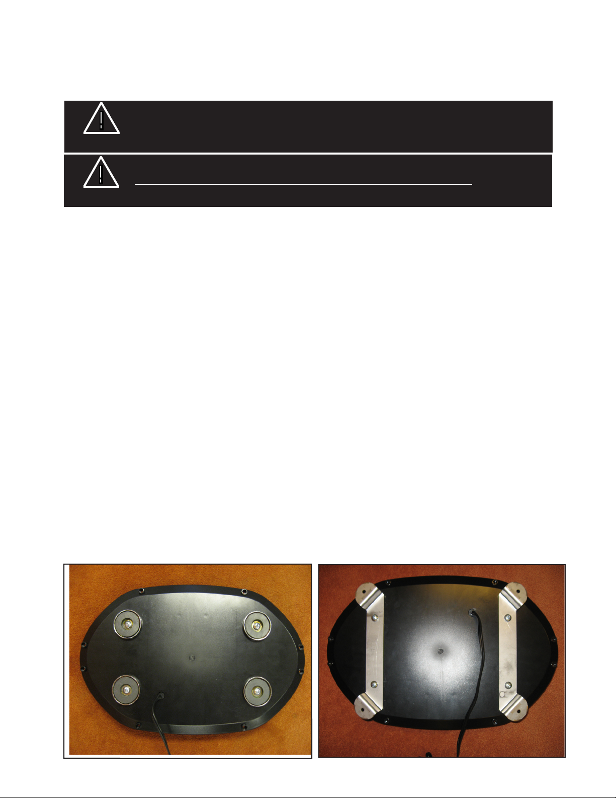
Magnetic Mounting:
As with any magnetially-mounted warning device, its use on the exterior of a moving vehicle is at the sole
discretion and responsibility of the user.
WARNING!
WARNING!
The magnetic based beacon provides a secure, temporary installation on a non-moving vehicle. The beacon
should be placed in the center of the roof where the least amount of curvature occurs. Check the magnet for
debris before installation. Any foreign matter can reduce holding power and scratch the vehicle. The roof surface
should be dry and have a dull, non-glossy nish. A glossy, highly waxed surface will reduce the magnet's holding power. When placed, the beacon should adhere rmly. The user should not attempt to drive with the beacon
magnetically mounted.
Permanent Mounting:
The permanent mount beacon provides a secure, permanent installation. Use the supplied brackets to mount
the beacon in the desired location. Wire routing should be taken into consideration when choosing a mounting
location.
Magnetic mounting provides a secure, temporary installation on a non-moving vehicle in most circumstances and is recommended for stationary use only.
This device, when magnetically mounted, is not intended for use on a moving vehicle.
Wiring Instructions
Magnetic Mounting:
The magnetic mount beacon is equipped with a light plug with rocker switch, that plugs into a 12 Volt DC cigarette
lighter outlet; rotate and push with reasonable moderate force to insure the best possible connection.
Permanent Mount:
For Permanent Mount applications, the light plug with rocker switch may be removed and directly wired to the
vehicles power supply. Make sure to properly fuse the beacon with 10A fuse.
Magnetic Mount Permanent Mount
3
Page 4

Operation:
Setting the Flash Pattern:
This beacon is equipped with a capacitive touch pattern selector function. To change ash pattern, simply
power on the beacon and then touch (with your nger) the center of the upper lens. Scroll through all of the
ash patterns by continuing to momentarily touch the center of the upper lens. Due to the capacitive touch
feature, this beacon also has special "locking" features for the ash patterns. Holding your nger to the center
of the upper lens for certain amounts of time function the unique features of the bar.
TIME FUNCTION
0 ~ 1 second NEXT PATTERN / ON
1 ~ 3 seconds PREVIOUS PATTERN
3 ~ 5 seconds FACTORY DEFAULT(PATTERN 1)
5 ~ 8 seconds LOCK/UNLOCK PATTERN
Flash Patterns:
PATTERN NO. PATTERNS
1 Single ash 75 sim all ash(factory Default)
2 Single ash 75 right-left
3 Single ash 375 right-left
4 Single ash 75 RIGHT/LEFT-FRONT/REAR
5 Single ash 75 Diagonal
6 Single ash 75 clockwise
7 Single ash 75 clockwise
8 Single ash 75 in-outward
9 Single ash 75 center-split
10 Single ash 75 ash
11 Double ash 75 sim all ash
12 Double ash 75 right-left
13 Swiftash 75 sim all ash
14 Swiftash 75 right-left
15 Quad Flash 75 sim all ash
16 Quad Flash 75 right-left
17 Five ash sim all
18 Five ash right-left
19 Modulation action ash sim all
20
21
AUTORUN
OFF
4
Page 5

Maintenance:
The beacons are completely sealed units designed to be maintenance free. Refer to the guide below for help
with troubleshooting. Should the unit be diagnosed as malfunctioning, remove unit and replace with a new
module.
LED module housings may become hot with extended use. Allow modules to cool completely
WARNING!
Problem Probable Cause Remedy
Lighthead does not activate a. No power to unit a. Check wire for loose connection
Pattern does not change a. Unit in Lock Mode a. Unlock Flash Patterns
before attempting to remove.
TROUBLESHOOTING
b. Power input wire reversed b. Reverse power wires
c. Damaged or shortaged cabling c. Check cables for damage
d. Defective lighthead d. Contact Service Dept.
5
Page 6

Dimensions (shown with permanent mount brackets)
Permanent Mounting Hole Locations
6
Page 7

NOTES
7
Page 8

WARRANTY
Code 3, Inc.'s L.E.D. emergency devices are tested and found to be operational at the time of manufacture.
Provided they are installed and operated in accordance with manufacturer's recommendations, Code 3, Inc. guarantees
all parts and components except the lamps to a period of 1 year, LED Lighthead modules to a period of 5 years (unless
otherwise expressed) from the date of purchase or delivery, whichever is later. Units demonstrated to be defective
within the warranty period will be repaired or replaced at the factory service center at no cost.
Use of lamp or other electrical load of a wattage higher than installed or recommended by the factory, or use
of inappropriate or inadequate wiring or circuit protection causes this warranty to become void. Failure or destruction
of the product resulting from abuse or unusual use and/or accidents is not covered by this warranty. Code 3, Inc.
shall in no way be liable for other damages including consequential, indirect or special damages whether loss is due
to negligence or breach of warranty.
CODE 3, INC. MAKES NO OTHER EXPRESS OR IMPLIED WARRANTY INCLUDING, WITHOUT LIMITATION, WARRANTIES OF FITNESS OR MERCHANTABILITY, WITH RESPECT TO THIS PRODUCT.
PRODUCT RETURNS
If a product must be returned for repair or replacement*, please contact our factory to obtain a Return
Goods Authorization Number (RGA number) before you ship the product to Code 3, Inc. Write the RGA number
clearly on the package near the mailing label. Be sure you use sufcient packing materials to avoid damage to
the product being returned while in transit.
*Code 3, Inc. reserves the right to repair or replace at its discretion. Code 3, Inc. assumes no responsibility or liability for expenses incurred for the removal and /or
reinstallation of products requiring service and/or repair.; nor for the packaging, handling, and shipping: nor for the handling of products return to sender after the service has been
rendered.
PROBLEMS OR QUESTIONS? CALL OUR TECHNICAL ASSISTANCE HOTLINE (314) 996-2800
WWW.CODE3PSE.COM
10986 N. Warson Road
St. Louis, Missouri 63114-2029—USA
Ph. (314) 426-2700 Fax (314) 426-1337
www.code3pse.com
Code 3, Inc.
Code 3® is a registered trademark of Code 3, Inc., a subsidiary of Public Safety Equipment, Inc.
8
Revision 0, 1/10 - Instruction Book Part No. T55332
©2010 Public Safety Equipment, Inc. Printed in USA
 Loading...