

Page 1
INSTALLATION MANUAL
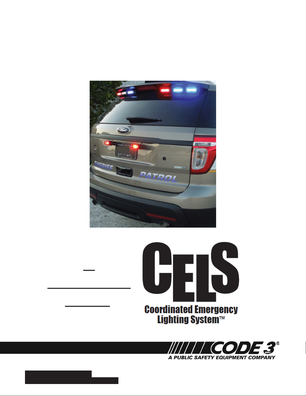
CITADEL
FORD PI SUV
A
COMPONENT
OF THE
For future reference record your product's serial no. here __________________________________________
IMPORTANT:
Read all instructions and warnings before installing and using.
This manual must be delivered to the end user of this equipment.
INSTALLER:
Page 2

Installation Instructions
Step-1. Raise liftgate (See Figure-1 on page 3) disconnect the (7) liftgate molding clips and remove the liftgate mold-
ing (See Figures 2, 3, and 4 on page 3) Note: Be very careful and make sure you pull the clips straight out as
the plastic retaining clips on the molding can break very easily!
Step-2. Locate and remove the (5) 13 mm 12 point socket nut fasteners attaching the rear spoiler to the shell (See
Figure-5 & 6 on page 3) Note: Be careful not to lose the center 12 point nut as it releases from the stud as it
can easily fall down inside the lift gate while you are trying to retrieve it through the hole in the lift gate.
Step-3. Push up rmly on the rear spoiler and disconnect the (4) spoiler clips shown in Figure 6 on page 3.
Step-4. Raise spoiler (See Figure-1) away from the vehicle to expose the Upper Rear Brake Light Electrical Connec-
tor and the Rear Window Washer Fluid Hose. Disconnect the Electrical Connector and the Washer Fluid Hose (See
Figure-7 on page 3).
Step-5. Remove spoiler from vehicle and lay it upside down on a protected surface to prevent scratches.
Step-6. Unplug the other end of the Upper Rear Brake Light Electrical Connector, carefully pull the red and black
wires out from under the wire retaining clip shown in Figure-8 on page 2 and pull the connector and wires back out of
the way (See Figure-9 on page 4).
Step-7. Position Citadel assembly over spoilers studs making sure the Citadel's Wires/Harness will not get pinched
(See Figures-10, 11, &12 on page 4), then reconnect the vehicle's Rear Brake Light Electrical Connector also making sure the connector is fully engaged and the wires will not get pinched (See Figure-13 on page 4). Make sure the
rubber grommets are securely in the slots in the Citadel Brackets on each side of the rear brake light (See Figures-14
& 15 on page 4).
Step-8. Route Citadel's Cable under the vehicle's OEM square foam seal pad (See Figure-16 on page 4). Route the
cable following the existing wiring from the brake light assembly back through the hole in the lift gate (See Figure-17
on page 4). Route the Citadel cable through the vehicle's rubber hose (See Figure-18 on page 4) and route the cable
to the desired nal destination.
Step-9. Position the spoiler back on the vehicle while pulling the slack out of the Citadel's cable.
Step-10. Reconnect the Upper Rear Brake Light Electrical Connector and the Rear Window Washer Fluid Hose.
Step-11. Position the Spoiler back in its home location, snap the (4) spoiler retention clips back into their respec-
tive holes, and thread the center 12 point nut onto the spoiler stud rst, followed by the remaining 12 point nuts and
torque the nuts in the same sequence. Torque nuts to 6 Nm (53 lb in).
Step-12. The light heads in the CELS version of the Citadel are all STEADY BURN ONLY and require the CELS
controller for power, lighting sequence, and ash patterns. See the Instruction Manual for the CELS-CC
Housing for wiring connections and ash patterns.
DO NOT APPLY 12 VOLTS DIRECTLY TO THE CITADEL WIRES AFTER IT IS CONNECTED TO THE CELS
CC BOX. IF THE CITADEL IS A COMPONENT OF THE CELS SYSTEM THE CC BOARD OR THE LIGHT
WARNING!
HEADS COULD BE DAMAGED BY APPLYING 12 VOLTS TO THE CC OUTPUTS!.
2
Page 3
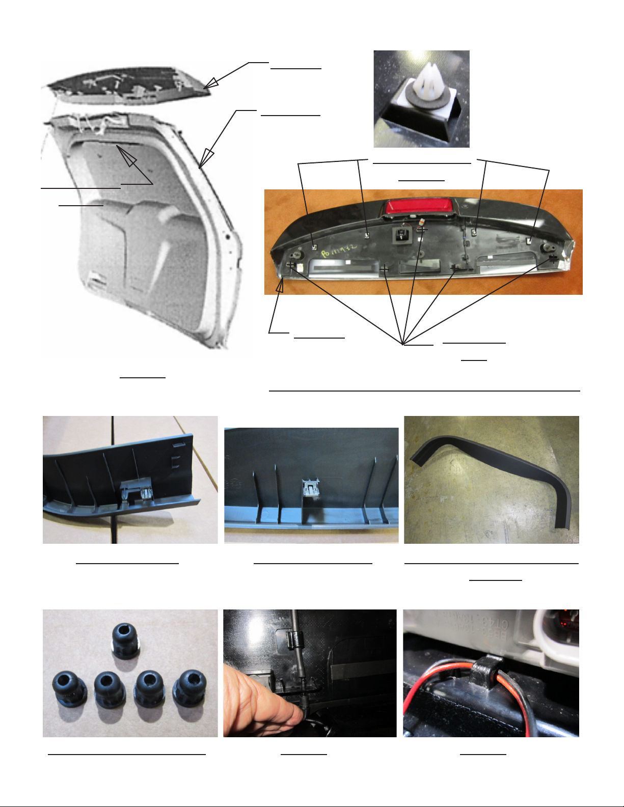
Rear Lift Gate
Molding
SPOILER
LIFT GATE
Spoiler Retention
Clips (4)
SPOILER
(5) 12 Point
Nuts
Figure-1
Figure-6---(4) Spoiler Retention Clips & (5) 12 Point Nuts
Figure-2 End Clips Figure-3 Center Clips Figure-4 Rear Lift Gate Molding
Removed
Figure-5 13mm12 Point Nuts Figure-7 Figure-8
3
Page 4

Figure-9 Figure-10 Figure-11
Figure-12 Figure-13 Figure-14
Figure-15 Figure-16 Figure-17
Figure-18
4
Page 5

WARNING!
This Product contains high intensity LED devices. To prevent eye damage,
DO NOT stare into light beam at close range.
Troubleshooting
All Citadel Products are thoroughly tested prior to shipment. However, should you encounter a problem during installation or during
the life of the product, follow the guide below for information on repair and troubleshooting. Additional information may be obtained
from the factory technical help line at 314-996-2800. Follow the guide below for information on repair and troubleshooting.
TROUBLESHOOTING GUIDE
PROBLEM
XT Module not operating when powered.
The use of this or any warning device does not ensure that all drivers can or will observe or react to an emergency
warning signal. Never take the right-of-way for granted. It is your responsibility to be sure you can proceed safely before
entering an intersection, driving against trafc, responding at a high rate of speed, or walking on or around trafc lanes.
The effectiveness of this warning device is highly dependent upon correct mounting and wiring. Read and follow the
manufacturer’s instructions before installing or using this device. The vehicle operator should insure daily that all features
of the device operate correctly. In use, the vehicle operator should insure the projection of the warning signal is not blocked
by vehicle components (i.e.: open trunks or compartment doors), people, vehicles, or other obstructions. This equipment
is intended for use by authorized personnel only. It is the user’s responsibility to understand and obey all laws regarding
emergency warning devices. The user should check all applicable city, state and federal laws and regulations. Code 3, Inc.,
assumes no liability for any loss resulting from the use of this warning device. Proper installation is vital to the performance
of this warning device and the safe operation of the emergency vehicle. It is important to recognize that the operator of the
emergency vehicle is under psychological and physiological stress caused by the emergency situation. The warning device
should be installed in such a manner as to: A) Not reduce the output performance of the system, B) Place the controls within
convenient reach of the operator so that he can operate the system without losing eye contact with the roadway. Emergency
warning devices often require high electrical voltages and/or currents. Properly protect and use caution around live electrical
connections. Grounding or shorting of electrical connections can cause high current arcing, which can cause personal
WARNING!
injury and/or severe vehicle damage, including re. Any electronic device may create or be affected by electromagnetic
interference. After installation of any electronic device operate all equipment simultaneously to insure that operation is free of
interference. Never power emergency warning equipment from the same circuit or share the same grounding circuit with radio
communication equipment. All devices should be mounted in accordance with the manufacturer's instructions and securely
fastened to vehicle elements of sufcient strength to withstand the forces applied to the device. Driver and/or passenger air
bags (SRS) will affect the way equipment should be mounted. This device should be mounted by permanent installation and
within the zones specied by the vehicle manufacturer, if any. Any device mounted in the deployment area of an air bag will
damage or reduce the effectiveness of the air bag and may damage or dislodge the device. Installer must be sure that this
device, its mounting hardware and electrical supply wiring does not interfere with the air bag or the SRS wiring or sensors.
Mounting the unit inside the vehicle by a method other than permanent installation is not recommended as unit may become
dislodged during swerving, sudden braking or collision. Failure to follow instructions can result in personal injury. PROPER
INSTALLATION COMBINED WITH OPERATOR TRAINING IN THE PROPER USE OF EMERGENCY WARNING DEVICES
IS ESSENTIAL TO INSURE THE SAFETY OF EMERGENCY PERSONNEL AND THE PUBLIC.
QUESTIONS POSSIBLE CAUSE
N/A
a. Bad power/ground
connection.
b. Defective module.
SOLUTION
a. Fix connection.
b. Replace module
5
Page 6

Notes:
6
Page 7

Notes:
7
Page 8

WARRANTY
Code 3, Inc.’s emergency devices are tested and found to be operational at the time of manufacture. Provided
they are installed and operated in accordance with manufacturer’s recommendations, Code 3, Inc. guarantees all
parts and components except the lamps to a period of 1 year, LED Lighthead modules to a period of 5 years (unless
otherwise expressed) from the date of purchase or delivery, whichever is later. Units demonstrated to be defective
within the warranty period will be repaired or replaced at the factory service center at no cost.
Use of lamp or other electrical load of a wattage higher than installed or recommended by the factory, or use
of inappropriate or inadequate wiring or circuit protection causes this warranty to become void. Failure or destruction
of the product resulting from abuse or unusual use and/or accidents is not covered by this warranty. Code 3, Inc.
shall in no way be liable for other damages including consequential, indirect or special damages whether loss is due
to negligence or breach of warranty.
CODE 3, INC. MAKES NO OTHER EXPRESS OR IMPLIED WARRANTY INCLUDING, WITHOUT LIMITATION, WARRANTIES OF FITNESS OR MERCHANTABILITY, WITH RESPECT TO THIS PRODUCT.
NEED HELP? Call our Technical Assistance HOTLINE - (314) 996-2800
PRODUCT RETURNS
If a product must be returned for repair or replacement*, please contact our factory to obtain a Return Goods
Authorization Number (RGA number) before you ship the product to Code 3, Inc. Write the RGA number clearly on
the package near the mailing label. Be sure you use sufcient packing materials to avoid damage to the product
being returned while in transit.
*Code 3, Inc. reserves the right to repair or replace at its discretion. Code 3, Inc. assumes no responsibility or liability for expenses incurred for the removal and /or reinstallation of
products requiring service and/or repair.; nor for the packaging, handling, and shipping: nor for the handling of products returned to sender after the service has been rendered.
St. Louis, Missouri 63114-2029—USA
Ph. (314) 426-2700 Fax (314) 426-1337
Code 3®, Inc.
10986 N. Warson Road
www.code3pse.com
Code 3 is a registered trademark of Code 3, Inc. a subsidiary of Public Safety Equipment, Inc.
Revision 0, 07/18/2013 - Instruction Book Part No. T15628
©2013 Code 3, Inc. Printed in USA
 Loading...