

Page 1
INST ALLATION
& OPERATION
MANUAL
MODEL
FM100C OR
FM100V
Patent Pending
Model FM100
IMPORTANT:
SPEAKER/FLUSHMOUNT
Contents:
Introduction..........................................................................2
Unpacking & Pre-Installation............................................... 3
Installation & Mounting ........................................................3
Maintenance........................................................................ 4
Cleaning ............................................................................4
Changing Drivers...............................................................5
Troubleshooting...................................................................5
Parts List (Replacement Parts / Exploded View).................6
Warranty/Product Returns...................................................7
Read all instructions and warnings before installing and using.
INSTALLER: This manual must be delivered to the end user of this equipment.
Page 2

Introduction
The FM100C and FM100V are modular speaker systems for mounting in the chassis of most top of the line
fire and emergency rescue vehicles. These highly effective warning units employ a mathematically designed
speaker for maximum sound volume whether used as a siren or public address system.
The use of this or any warning device does not insure that all drivers can or will observe or
react to an emergency warning signal. Never take the right-of-way for granted. It is your
responsibility to be sure you can proceed safely before entering an intersection, driving
against traffic, responding at a high rate of speed, or walking on or around traffic lanes.
The effectiveness of this warning device is highly dependent upon correct mounting and
wiring. Read and follow the manufacturer’s instructions before installing or using this
!
WARNING!
device. The vehicle operator should insure daily that all features of the device operate
correctly. In use, the vehicle operator should insure the projection of the warning signal is
not blocked by vehicle components (i.e.: open trunks or compartment doors), people,
vehicles, or other obstructions.
This equipment is intended for use by authorized personnel only. It is the user’s responsibility to understand and obey all laws regarding emergency warning devices. The user
should check all applicable city, state and federal laws and regulations.
Public Safety Equipment, Inc., assumes no liability for any loss resulting from the use of
this warning device.
Proper installation is vital to the performance of this warning device and the safe operation
of the emergency vehicle. It is important to recognize that the operator of the emergency
vehicle is under psychological and physiological stress caused by the emergency situation.
The warning device should be installed in such a manner as to: A) Not reduce the output
performance of the system, B) Place the controls within convenient reach of the operator
so that one can operate the system without losing eye contact with the roadway.
Emergency warning devices often require high electrical voltages and/or currents. Properly
protect and use caution around live electrical connections. Grounding or shorting of
electrical connections can cause high current arcing, which can cause personal injury and/
or severe vehicle damage, including fire.
PROPER INSTALLATION COMBINED WITH OPERATOR TRAINING IN THE PROPER
USE OF EMERGENCY WARNING DEVICES IS ESSENTIAL TO INSURE THE SAFETY
OF EMERGENCY PERSONNEL AND THE PUBLIC.
!
WARNING!
SIREN PRODUCTS:
Sirens are an integral part of an effective audio/visual emergency warning system. However, sirens are only short range secondary warning devices. The use of a siren does not
insure that all drivers can or will observe or react to an emergency warning signal, particularly at long distances or when either vehicle is traveling at a high rate of speed. Sirens
should only be used in a combination with effective warning lights and never relied upon as
a sole warning signal. Never take the right of way for granted. It is your responsibility to
be sure you can proceed safely before entering an intersection, driving against traffic, or
responding at a high rate of speed.
The effectiveness of this warning device is highly dependent upon correct mounting and
wiring. Read and follow the manufacturer’s instructions before installing or using this
device. The vehicle operator should check the equipment daily to insure that all features of
the device operate correctly.
To be effective, sirens must produce high sound levels that potentially can inflict hearing
damage. Installers should be warned to wear hearing protection, clear bystanders from
the area and not to operate the siren indoors during testing. Vehicle operators and occupants should assess their exposure to siren noise and determine what steps, such as
consultation with professionals or use of hearing protection should be implemented to
protect their hearing.
2
Page 3

This equipment is intended for use by authorized personnel only. It is the user’s responsi-
!
!
WARNING!
SIREN PRODUCTS:
bility to understand and obey all laws regarding emergency warning devices. The user
should check all applicable city, state and federal laws and regulations.
Public Safety Equipment, Inc., assumes no liability for any loss resulting from the use of
this warning device.
Proper installation is vital to the performance of the siren and the safe operation of the
emergency vehicle. It is important to recognize that the operator of the emergency vehicle
is under psychological and physiological stress caused by the emergency situation. The
siren system should be installed in such a manner as to: A) Not reduce the acoustical
performance of the system, B) Limit as much as practical the noise level in the passenger
compartment of the vehicle, C) Place the controls within convenient reach of the operator
so that he can operate the system without losing eye contact with the roadway.
Emergency warning devices often require high electrical voltages and/or currents. Properly protect and use caution around live electrical connections. Grounding or shorting of
electrical connections can cause high current arcing, which can cause personal injury and/
or severe vehicle damage, including fire.
PROPER INSTALLATION COMBINED WITH OPERATOR TRAINING IN THE PROPER
USE OF EMERGENCY WARNING DEVICES IS ESSENTIAL TO INSURE THE SAFETY
OF EMERGENCY PERSONNEL AND THE PUBLIC.
Unpacking and Preinstallation
Carefully unpack the unit and check the contents against the parts list on page #6 of this booklet. Report any damage to carrier
immediately.
Installation and Mounting
Larger wires and tight connections will provide longer service life for components. For high
current wires it is highly recommended that terminal blocks or soldered connections be used
with shrink tubing to protect the connections. Do not use insulation displacement
connectors (e.g. 3M® Scotchlock type connectors). Route wiring using grommets and
WARNING!
sealant when passing through compartment walls. Minimize the number of splices to
reduce voltage drop. High ambient temperatures (e.g. underhood) will significantly reduce
the current carrying capacity of wires, fuses, and circuit breakers. Use "SXL" type wire in
engine compartment. All wiring should conform to the minimum wire size and other
recommendations of the manufacturer and be protected from moving parts and hot
surfaces. Looms, grommets, cable ties, and similar installation hardware should be used to
anchor and protect all wiring.
Fuses or circuit breakers should be located as close to the power takeoff points as possible
and properly sized to protect the wiring and devices.
Particular attention should be paid to the location and method of making electrical
connections and splices to protect these points from corrosion and loss of conductivity.
Ground terminations should only be made to substantial chassis components, preferably
directly to the vehicle battery.
The user should install a fuse sized to approximately 125% of the maximum Amp capacity
in the supply line to protect against short circuits. For example, a 30 Amp fuse should
carry a maximum of 24 Amps. DO NOT USE 1/4" DIAMETER GLASS FUSES AS THEY
ARE NOT SUITABLE FOR CONTINUOUS DUTY IN SIZES ABOVE 15 AMPS. Circuit
breakers are very sensitive to high temperatures and will "false trip" when mounted in hot
environments or operated close to their capacity.
3
Page 4

NOTE : All of the information listed in this booklet
must be given to the end user by the installer.
1) Cut a hole in the desired mounting location to
the dimensions shown in Figure 1. Make sure
this hole is properly oriented to a structural
member of the vehicle for a secure mounting.
This installation may require the use of spacers or longer mounting screws to bring the
product to the desired orientation with the
exterior surface. In some installations it may
be necessary to fabricate a special adaptor
plate to achieve the desired position on the
vehicle.
2) Hold speaker assemblies against the bumper
and inscribe locations for drilling holes for the
mounting screws.
3) At the inscribed positions, drill holes for the
provided 1/4" x 2-1/2" screws using a 9/32"
drill bit.
7.00"
6.25"
4) Attach the speaker assemblies and bezel to
the vehicle using the fasteners shown in
Figure 2. Make sure that the siren wires are
clear of the mounting bracket to avoid damage during installation. In addition, DO NOT
TIGHTEN the mounting screws completely
until the speaker is parallel and evenly
positioned with the holes on the vehicles
exterior.
5) Connect the wires from the speaker assem-
bly to the leads coming from the siren control
head.
NOTE: When two or more speakers are to
be operated by the same control head, the
speakers must be connected in phase. In
order to accomplish this, the white wires,
which are connected to the number 1 terminals on the siren drivers, must be connected
together to the same output terminal on the
siren amplifier. Likewise, the blue wires,
which are connected to the number 2 terminals on the drivers, must be connected
together on the other output terminal of the
siren amplifier.
FIGURE 1
1
2
FIGURE 2
Maintenance
Maintenance of your FM100C and FM100V involves the cleaning of the unit and in some cases the replacement of the siren driver, if required.
Cleaning
Clean with soap and water to remove all salt, dirt or mud. Do not use any abrasive cleaners or harsh chemicals because the protective coating on the aluminum may be damaged allowing the exposed aluminum to dull
in appearance or corrode.
4
Page 5

Changing Drivers
Allow the unit to cool for five minutes before attempting any maintenance. For replacing an inoperable driver,
the speaker bracket assembly must be removed from the vehicle in reverse order as explained in the installation procedure. Follow the steps below once this has been accomplished. (see Figure 3)
1) Remove the driver cap on the front face of the speaker assembly and place it on a flat surface.
2) Remove the four screws on the back of the assembly and disassemble the bracket, speaker bell and
driver cover.
3) Detach the wires from the inoperable driver and reconnect them to the appropriate terminals on the
replacement driver.
4) Reassemble the speaker assembly to its original state and reattach it to the vehicle following the same
steps outlined in the installation and mounting section in this booklet. Make sure the wires are tightly
sealed at all exit points from the speaker assembly. Fill any voids with silicone caulking.
NOTE: When reassembling the speaker, make sure to align the drain holes on the driver, driver cover and
driver cap (the drain hole on the Atlas driver is located behind a metal tag). These holes should be
oriented to the base of speaker/bracket assembly for proper drainage and orientation of the logo on the
driver cap.
Trouble-shooting guide
PROBLEM (SPEAKER)
NO OUTPUT FROM SPEAKER, SIREN
AMPLIFIER MAKES NOISE
LOW OUTPUT FROM SPEAKER
PROBABLE CAUSE
1) OPEN CIRCUIT IN SPEAKER
WIRING
2) DEFECTIVE DRIVERS
1) LOW OUTPUT VOLTAGE FROM
AMPLIFIER
2) DUAL SPEAKERS NOT
CONNECTED IN PHASE
REMEDY
1) CHECK CONNECTIONS AT AMPLIFIER AND SIREN AMPLIFIER
2) CHECK RESISTANCE ACROSS
SPEAKER WIRES. (3.8 OHMS) AND
REPLACE DRIVERS
1) REFER TO SIREN AMPLIFIER
OWNERS MANUAL
2) REFER TO SPEAKER WIRING
INSTRUCTION IN MANUAL
5
Page 6
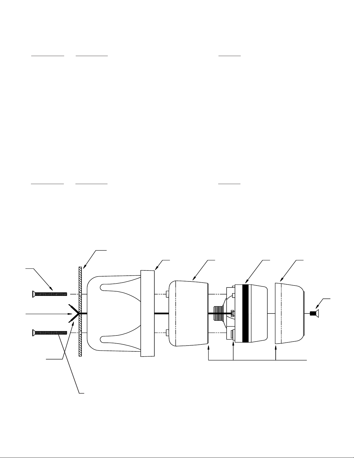
Parts & Exploded Views
Ref Number Description Part No.
3 Speaker wire Assemblies T04346 & T04347
4 Speaker Screws T06519
5 Speaker Horn S85477
6 Driver Cover T03739
7 100w Siren Driver T03470
8 Driver Cap S85478
9 Nose Cone Screw T09204
Parts Shown in Fig. 2
Ref Number Description Part No.
1 Coated Mounting Bracket S35470
2 Trim Bezel T03776
4
Do not
leave any
slack in
speaker
wires
during
assembly.
Top edge of bracket
must be opposite of
drain holes.
5
3
FIGURE 3
Self Tapping
(Thread Clearing)
6
7
8
9
All drain holes
must be
alligned on the
lower end of
speaker
bracket.
6
Page 7

NOTES
Page 8

WARRANTY
This product was tested and found to be operational at the time of manufacture. Provided this product is
installed and operated in accordance with the manufacturer's recommendations, Public Safety Equipment
guarantees all parts and components except the lamps for a period of 1 year from the date of purchase or
delivery, whichever is later. Units demonstrated to be defective within the warranty period will be repaired or
replaced at the factory service center at no cost.
Use of a lamp or other electrical load of a wattage higher than installed or recommended by the factory,
or use of inappropriate or inadequate wiring or circuit protection causes this warranty to become void. Failure
or destruction of the product resulting from abuse or unusual use and/or accidents is not covered by this
warranty.
PSE shall in no way be liable for other damages including consequential, indirect or special damages
whether loss is due to negligence or breach of warranty.
PSE MAKES NO OTHER EXPRESS OR IMPLIED WARRANTY INCLUDING, WITHOUT LIMITATION, WARRANTIES OF FITNESS OR MERCHANTABILITY, WITH RESPECT TO THIS PRODUCT.
PRODUCT RETURNS
In order to provide you with faster service, if you are going to return a product for repair or replacement*,
please contact our factory to obtain a Return Goods Authorization Number (RGA number) before you ship the
product to PSE. Write the RGA number clearly on the package near the mailing label. Be sure you use
sufficient packing materials to avoid damage to the product being returned while in transit.
*PSE reserves the right to repair or replace product at its discretion. PSE assumes no responsibility or liability for expenses
incurred for the removal and/or reinstallation of products requiring service and/or repair.
PROBLEMS OR QUESTIONS? CALL OUR TECHNICAL ASSISTANCE HOTLINE (314) 996-2800
WWW.CODE3PSE.COM
Public Safety Equipment (UK), Ltd. Public Safety Equipment, Inc.
Oldham Road, Rishworth 10986 N. Warson Road
Halifax, West Yorkshire—ENGLAND HX6 4QG St. Louis, Missouri 63114-2029—USA
Ph. 0422-824640 Fax 0422-824604 Ph. (314) 426-2700 Fax (314) 426-1337
Code 3 is a registered trademark of Public Safety Equipment, Inc.
3M is a registered trademark of 3M Company Inc.
Revision 3, 09/97- Instruction Book Part No. 3778
©1997 Public Safety Equipment, Inc. Printed in USA
 Loading...