

Page 1
INSTALLATION
&
OPERATION
MANUAL
SERIES
800
Contents:
®
Introduction......................................................... 2
Unpacking & Pre-Installation .............................. 2
Installation & Mounting ....................................... 2
Mounting............................................................. 3
Wiring Instructions ........................................... 4-5
Multi-flash ........................................................... 5
Flash Pattern Selection ...................................... 5
Disassembly/Assembly....................................... 5
Maintenance ....................................................... 5
Disassembly/Assembly...................................... 5
Lens Replacement ............................................. 5
Halogen Lamp/Flashtube Replacement ............. 6
Flashtube Replacement for Remote Model ........ 6
Troubleshooting .................................................. 7
Parts List (Replacement Parts/Exploded View)8-9
Options and Specifictions ................................... 9
Warranty ........................................................... 10
IMPORTANT:
Read all instructions and warnings before installing and using.
INSTALLER:
This manual must be delivered to the end user of this equipment.
Page 2

ING!
Introduction
The DeckBlaster® product line represents the latest advances in low cost directional dash and deck-mountable warning lights. Designed for durability and high reliability, the Deckblaster’s low-profile design makes it
ideal for use in many applications. The line boasts five separate models, available in both strobe and halogen
configurations. These include a basic flashing halogen, a basic flashing strobe, a switchable halogen, a
steady burn halogen and a remote strobe.
The use of this or any warning device does not insure that all drivers can or will observe or
react to an emergency warning signal. Never take the right-of-way for granted. It is your
responsibility to be sure you can proceed safely before entering an intersection, driving
against traffic, responding at a high rate of speed, or walking on or around traffic lanes.
!
WARNING!
The effectiveness of this warning device is highly dependent upon correct mounting and
wiring. Read and follow the manufacturer’s instructions before installing or using this
device. The vehicle operator should insure daily that all features of the device operate
correctly. In use, the vehicle operator should insure the projection of the warning signal is
not blocked by vehicle components (i.e.: open trunks or compartment doors), people,
vehicles, or other obstructions.
This equipment is intended for use by authorized personnel only. It is the user’s responsibility to understand and obey all laws regarding emergency warning devices. The user
should check all applicable city, state and federal laws and regulations.
Public Safety Equipment, Inc., assumes no liability for any loss resulting from the use of
this warning device.
Proper installation is vital to the performance of this warning device and the safe operation
of the emergency vehicle. It is important to recognize that the operator of the emergency
vehicle is under psychological and physiological stress caused by the emergency situation.
The warning device should be installed in such a manner as to: A) Not reduce the output
performance of the system, B) Place the controls within convenient reach of the operator
so that he can operate the system without losing eye contact with the roadway.
Emergency warning devices often require high electrical voltages and/or currents. Properly
protect and use caution around live electrical connections. Grounding or shorting of
electrical connections can cause high current arcing, which can cause personal injury and/
or severe vehicle damage, including fire.
PROPER INSTALLATION COMBINED WITH OPERATOR TRAINING IN THE PROPER
USE OF EMERGENCY WARNING DEVICES IS ESSENTIAL TO INSURE THE SAFETY
OF EMERGENCY PERSONNEL AND THE PUBLIC.
Unpacking & Pre-installation
Carefully remove the unit from the box, taking care not to scratch the lens, and examine it for any transit
damage. You may wish to test the unit for proper operation before installation. To test models with a cigarette
plug, firmly twist the plug on the unit into a +12 Volt D.C. cigarette lighter. For models without a plug, touch
the black wire to ground (earth) and the red wire to the +12 Volt D.C. A battery may be used for this purpose.
For the remote strobe, plug the connector into an appropriate CODE 3 strobe power supply. If the vehicle has
an electrical system other than +12 Volts D.C. negative ground (earth), contact your local representative or
call the Electronics Technical Assistance HOTLINE at (314)426-2700 Ext. 2131 for instructions.
NOTE: Flashing halogen and strobe units will require a filtered power supply for proper operation
without a battery.
Installation & Mounting
!
WARNING!
This unit must be mounted within the interior passenger compartment of the vehicle only.
It is not intended for use in exterior applications.
2
Page 3
Mounting
This product, as with any device used inside a vehicle, may cause severe personal injury if not
!
WARNING!
properly mounted and secured. Objects used in the interior of a vehicle may become airborne
during a collision or other sudden changes in vehicle speed or direction, such as braking,
acceleration or turns.
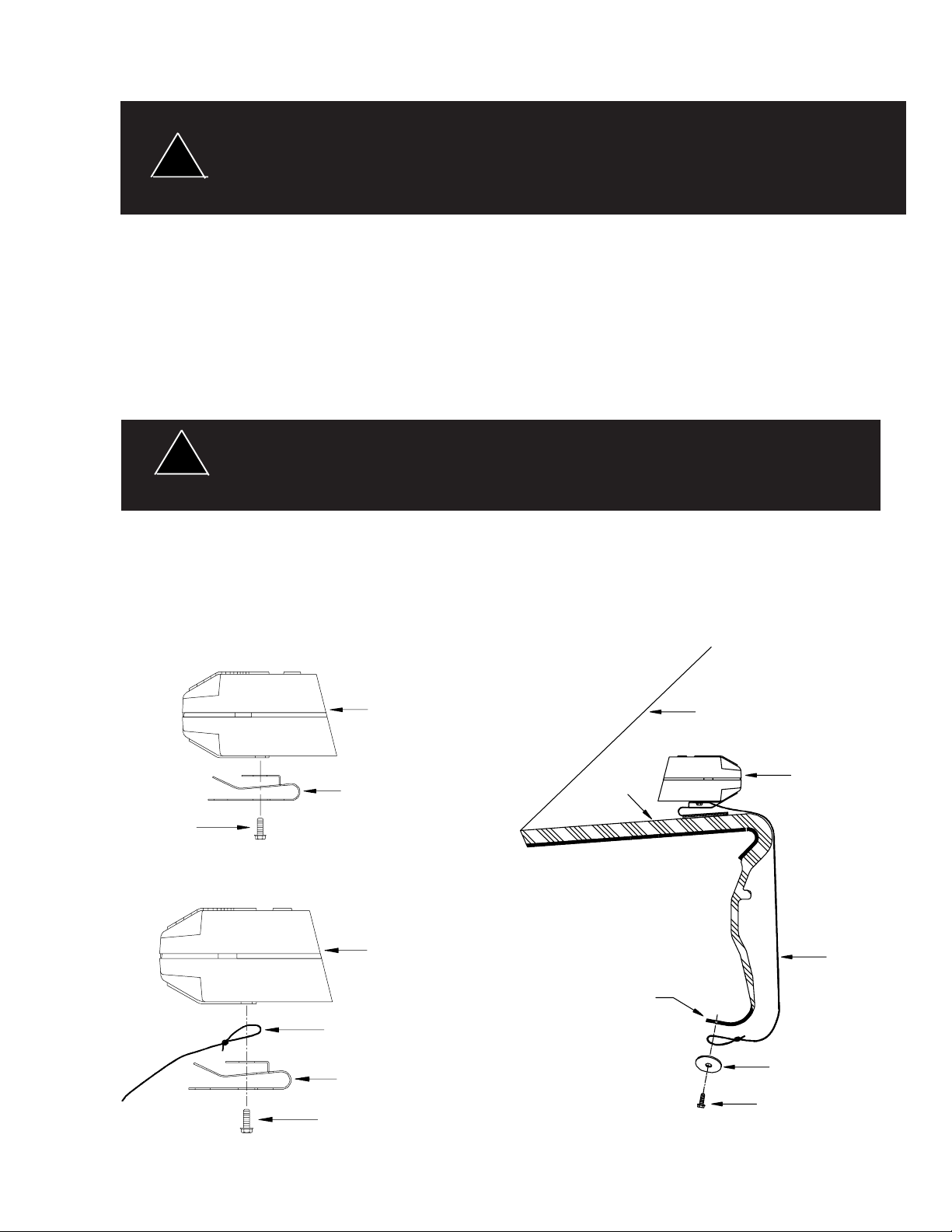
Permanent Mounting
Attach the basic mounting bracket to the bottom of the unit using the two screws supplied in the mounting
kit as shown in Fig. 1. Position the unit as desired and secure to the dash or deck with user-supplied hardware
(2 sheet metal screws or the adhesive strip). The bracket may be bent to allow for different windshield, dash,
or deck angles. For mounting multiple units in the rear-deck , CODE 3 offers an optional rear-deck mounting
kit for a four unit system, see part list on page 7 for ordering.
Temporary Mounting (Optional)
!
This product is supplied with a tether cord for added user safety. DO NOT use this product
without the tether cord properly installed.
WARNING!
CODE 3 offers two temporary mounting kits for the Deckblaster: Hook and Loop and Suction-Cup mounting
kits. CODE 3's Hook and Loop kit features Scotchmate® Hook and Loop strips with PV2000 adhesive, which
is designed for plasticized vinyls. CODE 3 does not recommend using a Hook and Loop type fastener without
the plasticized vinyl adhesive. See parts list on page 7 for ordering the Hook and Loop kit or the SuctionCup kit. See Fig. 2 and Fig. 3 for proper installation of the tether cord when mounting the Deckblaster in a
temporary position.
Fig. 1
Screw
DeckBlaster
Mounting Bracket
Dash
Fig. 3
Windshield
DeckBlaster
Fig. 2
DeckBlaster
Tether Cord
Mounting Bracket
Screw
Tether Cord
Sheet Metal
Drill 9/64" Hole
if Needed
Washer (supplied)
Screw (supplied)
3
Page 4

.Wiring Instructions
Use a minimum of 16 gauge wire or 14 gauge on runs longer than 15 ft. Larger wires and
tight connections will provide longer service life for components. For high
current wires it is highly recommended that terminal blocks or soldered connections be used
with shrink tubing to protect the connections. Do not use insulation displacement
connectors (e.g. 3M® Scotchlock type connectors). Route wiring using grommets and
sealant when passing through compartment walls. Minimize the number of splices to
!
WARNING!
reduce voltage drop. High ambient temperatures (e.g. underhood) will significantly reduce
the current carrying capacity of wires, fuses, and circuit breakers. Use "SXL" type wire in
engine compartment. All wiring should conform to the minimum wire size and other
recommendations of the manufacturer and be protected from moving parts and hot
surfaces. Looms, grommets, cable ties, and similar installation hardware should be used to
anchor and protect all wiring.
Fuses or circuit breakers should be located as close to the power takeoff points as possible
and properly sized to protect the wiring and devices.
Particular attention should be paid to the location and method of making electrical
connections and splices to protect these points from corrosion and loss of conductivity.
Ground terminations should only be made to substantial chassis components, preferably
directly to the vehicle battery.
The user should install a fuse sized to approximately 125% of the maximum Amp capacity
in the supply line to protect against short circuits. For example, a 30 Amp fuse should
carry a maximum of 24 Amps. DO NOT USE 1/4" DIAMETER GLASS FUSES AS THEY
ARE NOT SUITABLE FOR CONTINUOUS DUTY IN SIZES ABOVE 15 AMPS. Circuit
breakers are very sensitive to high temperatures and will "false trip" when mounted in hot
environments or operated close to their capacity. ALL PSE 4-HEAD POWER SUPPLIES
MUST BE USED WITH FOUR REMOTE UNITS. USE OF 4-HEAD POWER SUPPLIES
WITH LESS THAN 4 REMOTE UNITS MAY RESULT IN THERMAL FAILURE, VOIDING
THE WARRANTY. (Note: See power supply instructions for remote strobe model
synchronization.)
NOTE: All DeckBlaster units are reverse polarity protected. No damage will result from incorrect
connection of the inputs if within the specified operating voltage range.
For models with a cigarette plug (basic halogen, basic strobe, switchable halogen), insert the plug firmly
into the lighter socket and twist to insure good electrical contact. The unit will flash when power is
connected to the socket. For the switchable halogen unit, move the switch to the desired operating
position; forward for steady-burn, center for off (no current draw), or to the rear for flashing mode.
For the remote strobe unit, insert the plug firmly into the output socket of an appropriate CODE 3 power
supply.
NOTE:
For the steady-burn halogen unit, connect one of the wires to ground (earth). Route the other wire to a
user-supplied switch or flasher and then, from the switch or flasher to the positive terminal of the battery
through a 10 amp fuse or circuit breaker.
4
Page 5

®
Multi-Flash (Model 805, mfg. after 12/95)
!
WARNING!
High voltages and or temperatures are present inside the unit. Disconnect from power and
wait 5 minutes prior to servicing. Use hand and eye protection when changing halogen
lamps or flashtubes.
Flash Pattern Slection
This Deckblaster is capable of producing four distinct multiple pulse flash patterns.
They are:
1. A two pulse flash, 80 primary flashes per minute.
2. A four pulse flash, 80 primary flashes per minute.
3. A flash cycle consisting of a two pulse flash followed by a four pulse flash, 40 flash cycles per minute.
4. A flash cycle consisting of a two pulse flash, followed by a three pulse flash, followed by a four pulse,
27 flash cycles per minute.
The flash pattern is factory set for the four pulse flash pattern, Optional flash patterns can be selected by
changing the placement of jumpers JP1 and JP2, located on the Deckblaster printed circuit board (see Fig.
4 below). Flash patterns can be changed an unlimited number of times.
Disassembly/Assembly
Turn the unit upside down, remove the four screws holding the case together and remove the bottom case
half by lifting upward. To assemble, reinstall the lower case half by aligning the lens slots with the lens and
sliding it down on the other case half. Take care to insure that the wires are not pinched. Do not overtighten
the screws.
Maintenance
Disassembly/Assembly
Turn the unit upside down, remove the four screws holding the case together and remove the bottom case
half by lifting upward. To assemble, reinstall the lower case half by aligning the lens slots with the lens and
sliding it down on to the other case half. Take care to insure that the wires are not pinched. Do not overtighten the screws.
Lens Replacement/Change
Remove the lens by lifting upward and sliding it out of the slots on the inside of the case. To change the lens
to a dual color, locate the lens halves of the desired colors from the parts bag (optional). With a slight twisting
motion, assemble the two halves into a single lens, taking care not to touch the inside of the lenses. Locate
the lens slots in the case and slide the assembled lens into the case. Reassemble the unit.
5
Page 6

!
WARNING!
Lamps are extremely hot! Allow to cool completely before attempting to remove. Gloves
and eye protection should be worn when handling halogen lamps as they are pressurized
and accidental breakage can result in flying glass.
Halogen Lamp/Flashtube Replacement for non-remote models
Remove the circuit board/reflector assembly. Using a needle-nose pliers,
straighten the leads of the tube or halogen lamp protruding through the
circuit board on the component side of the board. Using hand protection,
grasp the lamp or tube gently and pull to remove from the reflector,
taking care not the break the glass. Replace with a CODE 3 approved
replacement as found in the parts list on page 7. When reinstalling
the halogen lamp, take care to note the lamp orientation as shown
on page 7. The red marking on the flashtube should be oriented
such that it is to the right side of the reflector when facing the unit in
it’s upright position, see Fig. 5. Incorrect installation could result in
premature failure of the flashtube or intermittent operation. Reassemble the
unit. Connect the unit to power to verify that it operates properly before reinstalling.
Heatsink Up
Fig. 5
Flashtube replacement for remote model
Disconnect the unit from the power supply and disassemble. Remove the bracket/reflector assembly from
the housing and unplug the power cable from the lamp. Using hand protection, grasp the lamp from the front
of the reflector and turn counterclockwise until it comes free. Pull the lamp forward through the reflector and
replace it with a CODE 3 approved replacement as found in the parts list on page 9. Reassemble the unit
by reversing the above steps.
1
Red Dot
6
5
7
4
8
2
3
6
Page 7

Deckblaster Parts List (Remote Model)Ref No. Description Part No.
Qty.
1 Upper Case Half T06570 1
2 Reflector Bracket S35321 1
3 Wiring - Straight Cord S35250 1
4 Reflector S81231 1
5 Flashtube S82108 1
6 Lens - Half w/Optics T0202X 2
- Half smooth T0204X 2
- Full w/Optics T0203X 1
- Full smooth T0206X 1
7 Lower Case Half T06571 1
8 Case Screws - #8x1/2", "B", Hex, Philips T00238 4
Not Shown Mounting bracket/Tether Cord Kit S65492 1
Rear-Deck Mounting Kit (Optional) RDMNT
Hook and Loop Mounting Kit (Optional) HLMNT
Suction-Cup Mounting Kit (Optional) SCMNT
Troubleshooting
PROBLEM PROBABLE CAUSE REMEDY
Unit does not flash. No power connected to unit. Connect unit to power.
Blown fuse. (External) Check user-installed fuse.
Replace with properly sized fuse.
Worn flashtube or halogen lamp.
Circuit board failure. Replace circuit board assembly
Reversed polarity on power. or send unit in for service.
Unit flashes intermittently Loose connection in wiring. Check wiring for loose connection.
Flashtube installed incorrectly. Check flashtube for proper instal-
Worn flashtube or halogen lamp. Replace flashtube or halogen
Light output appears dim. Dirty lens. Clean lens.
Voltage drop in wiring. Check power wire sizing. Replace
Worn flashtube or halogen lamp
Replace flashtube or halogen lamp
with recommended replacement.
lation as illustrated in Fig. 6.
lamp with recommended replacement.
with larger wire to reduce voltage
drop.
Replace flashtube or halogen lamp
with recommended replacement.
Flashrate not correct Low input voltage. Check input voltage to unit and
make sure it is between 10 and
16 VDC.
7
Page 8

1
8
6
7
9
4
5
2
3
Deckblaster Parts List (Non-Remote Models)
10
Ref No. Description Part No. Qty.
1 Upper Case Half T06570 1
2 Circuit Board - Basic Halogen S65175 1
- Basic Strobe S70170
- Switchable Halogen S65190
3 Wiring - Straight Cord S65490 1
- Coil Cord S65493
- Steady Burn Wires S65497
4 Reflector T05555 1
5 Flashtube Grommet (strobe only) T03341 2
6 Flashtube T07210 1
7 Halogen Lamp (27 Watt) T03346 1
8 Lens - Half w/Optics T0202X 2
- Half smooth T0204X 2
- Full w/Optics T0203X 1
- Full smooth T0206X 1
9 Lower Case Half T06571 1
10 Case Screws - #8x1/2", "B", Hex, Philips T00238 4
Not Shown Mounting bracket/Tether Cord Kit S65492 1
Rear-Deck Mounting Kit (Optional) RDMNT
Hook and Loop Mounting Kit (Optional) HLMNT
Suction-Cup Mounting Kit (Optional) SCMNT
8
Page 9

Options and Specifications
Operating voltage range: 10-16 VDC (Currents are calculated at 12.8 volts)
PRODUCT HEIGHT WIDTH CURRENT FLASH- ENERGY OR
(MODEL) DRAW RATE
Basic Strobe (805) 2.50" 5.65" 2.5 A 80 9 J
Basic Halogen 2.50" 5.65" 1.25 A 110 27 W
(800)
Switchable Halogen 2.50" 5.65" 1.25 A 110 27 W
(810) (flash)
Steady Burn 2.50" 5.65" 2.5 A N/A 27 W
Halogen (820) (steady)
NOTES
POWER
9
Page 10

WARRANTY
This product was tested and found to be operational at the time of manufacture. Provided
this product is installed and operated in accordance with the manufacturer's recommendations,
Public Safety Equipment guarantees all parts and components except the lamps for a period of 1
year from the date of purchase or delivery, whichever is later. Units demonstrated to be defective within the warranty period will be repaired or replaced at the factory service center at no
cost.
Use of a lamp or other electrical load of a wattage higher than installed or recommended
by the factory , or use of inappropriate or inadequate wiring or circuit protection causes this
warranty to become void. Failure or destruction of the product resulting from abuse or unusual
use and/or accidents is not covered by this warranty.
CODE 3 shall in no way be liable for other damages including consequential, indirect or
special damages whether loss is due to negligence or breach of warranty.
CODE 3 MAKES NO OTHER EXPRESS OR IMPLIED WARRANTY INCLUDING, WITHOUT LIMITATION, WARRANTIES OF FITNESS OR MERCHANTABILITY, WITH RESPECT
TO THIS PRODUCT.
PRODUCT RETURNS
In order to provide you with faster service, if you are going to return a product for
repair or replacement*, please contact our factory to obtain a Return Goods Authorization
Number (RGA number) before you ship the product to CODE 3. Write the RGA number
clearly on the package near the mailing label. Be sure you use sufficient packing materials
to avoid damage to the product being returned while in transit.
*CODE 3 reserves the right to repair or replace product at its discretion. CODE 3 assumes no responsibility
or liability for expenses incurred for the removal and/or reinstallation of products requiring service and/or repair.
Problems or Questions? Call The Electronics Technical Assistance HOTLINE - (314) 996-2800
10986 N. Warson Road
www.code3pse.com
©2005 Code 3, Inc. Printed in USA
Code 3 & Deckblaster are registered trademarks of Code 3, Inc. a subsidiary of Public Safety Equipment, Inc.
3M and Scotchmate are registered trademarks of 3M Company
St. Louis, Missouri 63114-2029—USA
Ph. (314) 426-2700 Fax (314) 426-1337
Revision 7, 11/2005 - Instruction Book Part No. T07192
Code 3, Inc.
 Loading...