

Page 1
INSTALLATION
& OPERATION
MANUAL
MODEL 660
Patent Number 4,931,768
Contents:
®
MODEL 660
PORTABLE WARNING LIGHT
Introduction (with warnings)................................ 2
Unpacking & Pre-Installation .............................. 2
Installation & Mounting ....................................... 3
Magnetic MountIing ............................................ 3
Roof Mounting ............................................... 4
Interior Mounting........................................... 4
Permanent Mounting .................................... 5
Pole or Stanchion Mounting ......................... 6
Direct Wiring ....................................................... 6
Maintenance ....................................................... 7
Options & Specifications .................................... 7
Parts List (Replacement Parts/Exploded View) . 8
Warnings for Lighting Products ..................... 9-10
Troubleshooting ................................................ 11
Warranty ........................................................... 12
IMPORTANT:
Read all instructions and warnings before installing and using.
INSTALLER:
This manual must be delivered to the end user of this equipment.
Page 2
Introduction
The Code 3® DashLaser® is a powerful warning device that exceeds all minimum SAE Class 1 standards for 360°
warning lights. It is actually brighter than some "full-sized" light bars.
The DashLaser is a rugged unit, designed for long service life in interior or exterior applications. Each unit comes
with a snap-on, fast release blinder that is specifically designed for continuous use on the DashLaser without
causing damage to the device. A multipurpose mounting system is also standard.
The use of this or any warning device does not insure that all drivers can or will observe
or react to an emergency warning signal. Never take the right-of-way for granted. It is
!
WARNING!
correctly. In use, the vehicle operator should insure the projection of the warning signal is not blocked by
vehicle components (i.e.: open trunks or compartment doors), people, vehicles, or other obstructions.
This equipment is intended for use by authorized personnel only. It is the user’s responsibility to understand
and obey all laws regarding emergency warning devices. The user should check all applicable city, state and
federal laws and regulations.
your responsibility to be sure you can proceed safely before entering an intersection,
driving against traffic, responding at a high rate of speed, or walking on or around traffic
lanes.
The effectiveness of this warning device is highly dependent upon correct mounting and
wiring. Read and follow the manufacturer’s instructions before installing or using this
device. The vehicle operator should insure daily that all features of the device operate
Code 3, Inc.
Proper installation is vital to the performance of this warning device and the safe operation of the emergency
vehicle. It is important to recognize that the operator of the emergency vehicle is under psychological and
physiological stress caused by the emergency situation. Warning devices should be installed in such a
manner as to: A) Not reduce the output performance of the system, B) Place the controls within convenient
reach of the operator so that he can operate the system without losing eye contact with the roadway.
Strobe power supply and flash tubes utilize high electrical voltages and/or currents. Properly protect and use
caution around live electrical connections. Grounding or shorting of electrical connections can cause high
current arcing, which can cause personal injury and/or severe vehicle damage, including fire. Incandescent
lamps are extremely hot, allow to cool completely before attempting to remove.
Any electronic device may create or be affected by electromagnetic interference. After installation of any
electronic device operate all equipment simultaneously to insure that operation is free of interference. Never
power emergency warning equipment from the same circuit or share the same grounding circuit with radio
communication equipment.
PROPER INSTALLATION COMBINED WITH OPERATOR TRAINING IN THE PROPER USE OF EMERGENCY WARNING DEVICES IS ESSENTIAL TO INSURE THE SAFETY OF EMERGENCY PERSONNEL
AND THE PUBLIC.
, assumes no liability for any loss resulting from the use of this warning device.
Unpacking & Pre-Installation
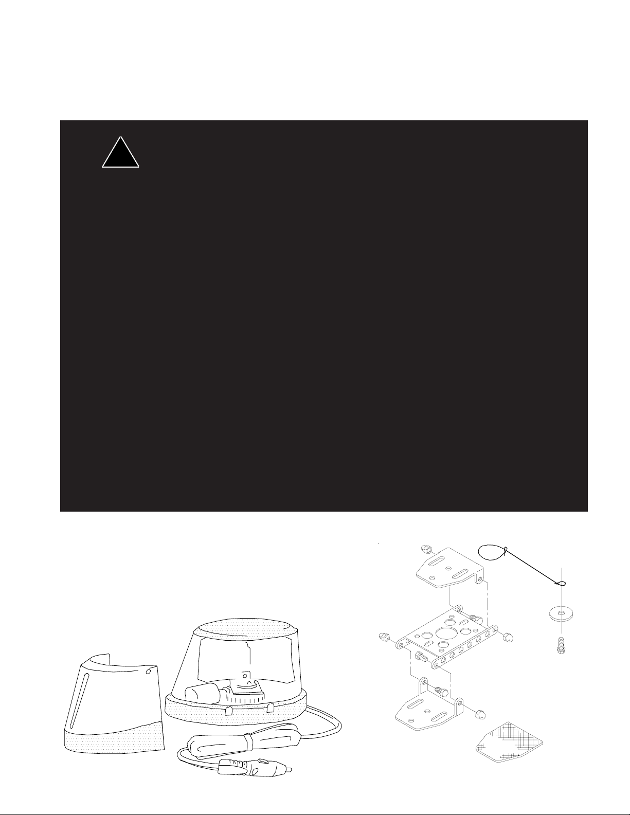
YOUR DASHLASER COMES WITH THESE ITEMS
(OPTIONAL IN SOME SPECIAL PACKAGES)
Carefully remove the beacon and place it on a flat surface, taking care not
to scratch the lens. Examine the unit for transit damage, broken lamps, etc.
TETHER CORD
LENS AND
ROTATOR
ASSEMBLY
SNAP-ON BLINDER
CORD AND PLUG
FIGURE 1
2
4 HEX-HEAD SCREWS
(one not shown)
4 ACORN NUTS
ADHESIVE PAD
Page 3
Operation
The DashLaser® is designed to operate on a 12-volt DC system, with a 7-15 amp
fuse.
To operate your DashLaser, just plug it into a cigarette lighter, rotate and push
with reasonable, moderate force which insures the best possible connec-
tion. It should be very bright and rotating at 90-110 rpm. If it is not,
check the troubleshooting guide on page 9 for appropriate
action.
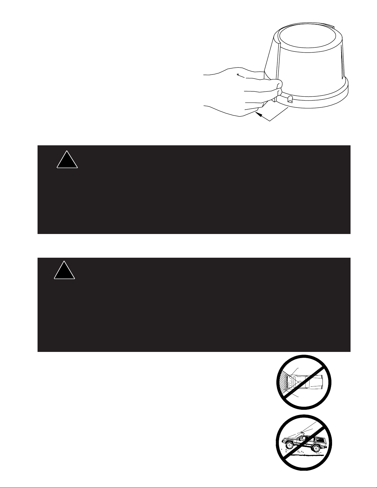
To remove the blinder, pull either side away from the lens
dome. The blinder will not release if you pull back on it. To
replace, line up the bottom of the blinder with the bottom of
the dome and gently push until it snaps into place. The
blinder will only fit on the sloped (motor) side of the dome.
The additional snap notches are there for accessories.
FIGURE 2
Installation & Mounting
All devices should be mounted in accordance with the manufacturer's instructions and se-
!
WARNING!
lodge the device. Installer must be sure that this device, its mounting hardware and electrical supply wiring
does not interfere with the air bag or the SRS wiring or sensors. Front or rear grille/bumper placement must
avoid interference with SRS sensors. Mounting the unit inside the vehicle by a method other than permanent
installation is not recommended as unit may become dislodged during swerving, sudden braking or collision.
Failure to follow instructions can result in personal injury.
curely fastened to vehicle elements of sufficient strength to withstand the forces applied to the
device. Driver and/or passenger air bags (SRS) will affect the way equipment should be
mounted. This device should be mounted by permanent installation and within the zones
specified by the vehicle manufacturer, if any. Any device mounted in the deployment area of
an air bag will damage or reduce the effectiveness of the air bag and may damage or dis-
Notice: This device is only useful as an SAE Class 1 warning device when mounted properly.
Magnetic Mounting
1) Rust Stains: The magnetic mount is not intended as a permanent mounting for the
!
WARNING!
part stores.
vehicle is at the sole discretion and responsibility of the user.
CAUTION: The magnet on the DashLaser is powerful and very reliable
except under extremely rough driving conditions, such as off-road and
4x4 use. When such rough conditions are anticipated, the DashLaser
should be removed temporarily or permanently mounted.
Random or careless placement in or on the vehicle may not produce a
safe in-motion warning signal. There is always great risk in breaking an
intersection or driving in the oncoming lane of traffic. A poorly aimed
warning light is very likely to lead to an accident.
beacon. Long duration usage of any magnet will expose the high iron content of the steel as
rust. The device should be removed when not used to prevent rust stains. Metallic debris
collected by the magnet will also contribute to rust stains. Insure that the magnet is kept
clean.
2) Surface rust stains can usually be removed with chrome polish, available at most auto
3) As with any magnetically-mounted warning device, its use on the exterior of a moving
This magnetic mount product provides a secure, temporary installation in most circum stances and is recommended for stationary use only. For maximum warning signal, mount
the beacon on the highest possible flat, level surface of the vehicle.
OPEN TRUNK
BLOCKED SIGNAL
To achieve the best signal, the DashLaser must be mounted level and
unobstructed. "Blind spots" can be caused by door posts, an open trunk
or hood, a passenger, the blinder, or vehicle operator. A full 360° signal
can only be achieved when the DashLaser is mounted externally on the
vehicle without the blinder.
3
FIGURE 3
Page 4
Roof Mounting
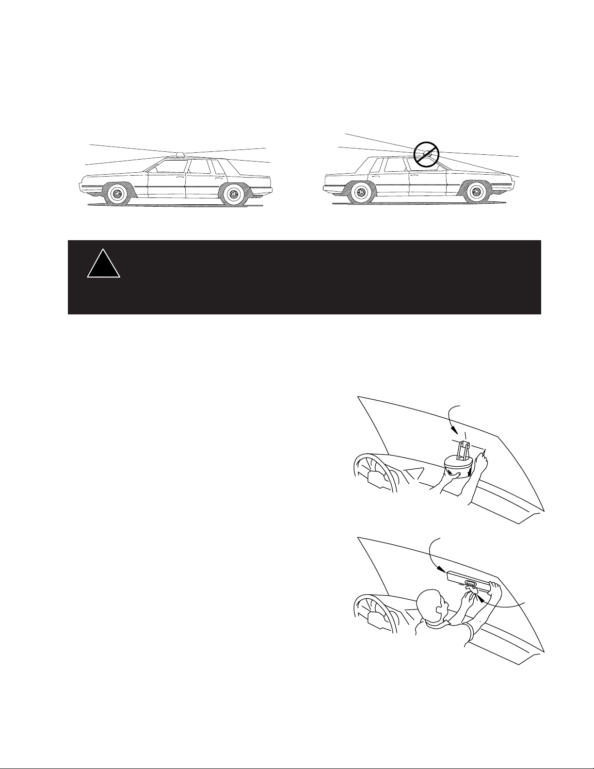
1. Park the vehicle on level ground. Use a carpenter's spirit level to be sure.
2. Place your DashLaser®, without the blinder, in the center of the roof.
3. Using a spirit level on the top of the dome, carefully move the device to where it is level (do not slide as it could
scratch the paint). This is the best location for maximum warning power. For future convenience, a small dot of
tape could be left on the roof to allow rapid accurate placement.
Be sure that the magnet is to the front of the vehicle and the slanted (motor) side is to the rear. The standard
DashLaser magnet is very reliable, but IS NOT SUITABLE for in-motion use on vinyl or convertible tops.
CORRECT MOUNTING INCORRECT MOUNTING
Interior Mounting
This product is supplied with a tether cord for added user safety. DO NOT use this product
!
WARNING!
See illustrations on page 4, 5 and 6 for proper installation of the tether cord when mounting inside vehicle.
Your DashLaser comes with a multipurpose mounting kit. For interior use the bracket can be mounted to clean
glass or flat painted metal surfaces with the adhesive pad provided. The adhesive bonds quickly and requires the
installer to read and understand this section before mounting.
1. Study the various mounting configurations in the illustrations on page 5 and assemble your bracket in the
manner you think works best for your application.
2. Wash the window with a non-filming glass cleaner.
3. Place the magnet on the bracket assembly with tether cord as
illustrated on page 6 and hold it in the desired position. Use a small
level on the upper surface to square it up.
4. Once it is level and positioned to your liking, use a crayon or
laundry marker to indicate the position. Do not mark in the area
where adhesive will be applied.
without the tether cord properly installed.
Using non-factory specified screws and/or mounting brackets and/or the improper number of
screws may result in failure of mounting system and severe damage to vehicle as well as
loss of warranty coverage on the equipment.
FIGURE 4
CROSS HAIR
MARKS
5. Clean the mounting bracket face and let dry. Remove one
adhesive pad liner and stick it to the bracket, rubbing down hard.
6. Remove the second liner from the pad. With the DashLaser off
of the bracket, and placing your level horizontally on the bracket to
keep it squared up right to left, press the bracket onto the window
in the pre-marked position. Press firmly to assure good adhesion
- you can look from the outside of a window to see if the surface is
making good contact with no bubbles. Never attempt to make an
adhesive bond when the surface or air temperature is below 50°F.
It will not hold. Once a good bond is made, it is not sensitive to
temperatures from -20° to +180°F. We do not recommend mounting to plastic dashboards with the adhesive pad since it will not
form an adequate bond with some plastics. Two additional screws
are included for attaching the bracket to surfaces where the selfadhesive pad cannot be used. See page 5 for "Permanent
Mounting".
7. Once unit is attached, locate a place on or under the dash that is sheet metal for mounting the tether cord. Hold
the free end of the cord in position and make sure the Dashlaser cannot reach the passenger or driver. Then attach
tether cord to this section of sheet metal (not to plastic or rubber) as shown in figure 7.
4
LEVEL
FIGURE 5
MOUNTING
BRACKET
Page 5

Removing the Adhesive Pad
1. Heat the adhesive area from the opposite side with a hot air
paint stripper or high-power hair dryer.
2. Carefully pry off with a wide flat head screwdriver or stiff
putty knife.
DASH
WINDSHIELD
DASHLASER
HEAT GUN
MOUNTING
SURFACE
VEHICLE
WINDSHIELD
FIGURE 6
ROTATE
SCREWDRIVER
BE CAREFUL NOT TO BLOCK
LIGHT WITH MOUNTING BKT.
VEHICLE
WINDSHIELD
TETHER CORD
SHEET METAL
WASHER (SUPPLIED)
SCREW (SUPPLIED)
FIGURE 7
MOUNTING
SURFACE
MOUNTING
SURFACE
VEHICLE
WINDSHIELD
VEHICLE
DASH
VEHICLE
DASH
VEHICLE
DASH
FIGURE 8
Permanent Mounting
Using non-factory specified screws and/or mounting brackets and/or the improper
!
WARNING!
1. Assemble and set up the bracket similar to the way described on page 4, using a level to keep it square.
Attach the bracket with a sheet-metal screw or through-bolt to the permanent mounting surface (the adhesive pad
may be used as a gasket).
2. If necessary, remove the section of the bracket that the DashLaser® will be mounted to.
3. Remove the screw holding the DashLaser's magnet in place. Align the holes in the bracket, magnet, and
dash light bottom plate, and replace with the supplied #8 x 7/8" screw, as shown.
4. Reassemble the bracket, level the light, and tighten the acorn nuts. You're ready to go.
Note: DO NOT externally mount the DashLaser upside down on the vehicle, to avoid excessive water leakage.
number of screws may result in failure of mounting system and severe damage to
persons or the vehicle as well as loss of warranty coverage on the equipment.
5
Page 6

PLUMBING
ELECTRICAL
CONDUIT
HARDWARE
Tether Cord
MAGNET
ACTS AS
SPACER
HARDWARE
FIGURE 9
Pole or Stanchion Mounting
The mounting kit can be used to mount the DashLaser® to a 1/2" or 3/4" pipe by using standard electrical (1/2") or
plumbing hardware (see illustrations).
Direct Wiring
If you wire the DashLaser directly to a power
source instead of using the cigarette plug, be
sure the wire from the DashLaser is positive,
and connects to the +12 volt power supply.
The smooth wire is the ground (earth) wire. It
is advisable to put a 10 amp in-line fuse on the
ribbed wire between the DashLaser and the
power source.
Permanently mounted units can be tipped to
remove lens. Clearances are shown here.
FIGURE 10
CUSTOMER SUPPLIED
SWITCH AND 10AMP FUSE
+12V
RIBBED WIRE IS
POSITIVE
SOLID CHASSIS
GROUND (EARTH)
FIGURE 11
6
Page 7

Maintenance
CAUTION: Allow the unit to cool for 10 minutes before attempting any maintenance.
The DashLaser® requires very little routine maintenance. Occasional cleaning of the dome and reflector is
all that is necessary to maintain maximum light output. Use plain water and a soft cloth, or Code 3® polish
and very soft paper towel or facial tissue. Since plastic scratches easily, we recommend cleaning only when
necessary.
!
Never activate the light with the dome removed!
WARNING!
Halogen lamps are pressurized, and get very hot when operating. The H1 halogen lamp is sensitive to natural
oils in your skin. Be sure not to touch the lamp when cleaning the reflector. If it is touched accidentally, gently
wipe off any fingerprints with alcohol and a soft cloth before replacing the dome and activating the light.
Do not oil the gears or bearings for any reason. Gears and bearings in the DashLaser are permanently
lubricated. Oiling them will actually shorten the service life of the unit. They may periodically be wiped or
blown clean, but this is not usually necessary.
Changing the Lamp
!
WARNING!
Lamps are extremely hot! Allow to cool completely before attempting to remove. Gloves
and eye protection should be worn when handling halogen lamps as they are pressurized
and accidental breakage can result in flying glass.
1. Allow 10 minutes for unit to cool. Remove the 3 screws on the underside of base plate. Holding the lens and
the base together, turn the unit right side up and lift off the lens.
2. Remove the retaining clip (reference #5 on page 8).
3. Lift lamp and reflector assembly until the lamp comes free from its connector.
4. Use ONLY 55-watt H1 type halogen lamps (Phillips #12258, Osram #64150 or equivalent). Higher wattage
lamps will cause damage to the DashLaser unit and void the warranty.
5. Do not touch the new lamp with your bare fingers. This will damage the lamp and shorten its life. If touched
accidently, it should be gently wiped off with alcohol and a soft cloth.
Options & Specifications
•5-FlashTM - Snap-on 4-step mirror increases directional flash rate to 400 flashes per minute. (Order PN 5FL)
•Multi-Colored Film - Red or Blue available as a kit. Attaches to existing molded 5-Flash and produces a red/
blue signal. (Order PN R-BKIT)
•Multi-Color - DashLaser-MTM produces attention getting 2-color warning signals in red and white, red and
amber, or blue and white at 400 flashes per minute. (Order Model No. 660FAR for red and amber, 660FCB for
blue and white, and 600FCR for red and white)
•Outlet Panel - Bracket with 1 or 2 sockets and switches lets you leave your DashLaser plugged in and ready
for action. (Order PN 661 for 1 socket, 662 for 2 sockets)
•Lenses - Impact resistant polycarbonate, in red, blue, amber, green or clear. (See Parts List for PN's)
•Extra Mounting Bracket - Allows you to set up several vehicles for using your DashLaser. (Order DSHMT)
•Lens Polish Kit - Removes minor scratches and restores visibility to your lens. (Order PN 102)
7
Page 8

DashLaser® Parts List (see illustration)
Ref No. Description Part No. Qty.
1 Lens - Amber T01554 1
- Red T01555
- Blue T01556
- Clear T01553
- Green T01557
2 PSE DashLight Assembly S18107 1
3 Reflector Assembly S96824 1
4 Motor Plate Assembly S96821 1
5 Retaining Washer T00928 1
6 Magnet T01587 1
7 55 Watt Bulb, H-1 T01543 1
8 Cigarette Lighter Plug Cord Set - Straight Cord T01590 1
- Coil Cord T02517
9 Sheet Metal Screws - #6 x 3/8" T01591 3
10 Sheet Metal Screw - #8 x 3/8" T00243 1
11 Molded 5-Flash - Optional 5FL 1
12 Molded Blinder or Color Filter - Black T01658 1
- Red T01691
- Blue T01692
13 DashLight Mounting Kit DASHMT 1
14 Dashmount Adhesive Pad T01665 1
15 Crimp Terminal T03313 1
16 Nylon Washer T04493 1
Parts Not Shown
Red/Blue Film for 5-Flash Mirrors R-BKIT 1
Fast Motor Plate Assy. S96839
8
Page 9

WARNINGS FOR LIGHTING PRODUCTS
!
IMPORTANT:
INTRODUCTION
The use of this or any warning device does not insure that all drivers can or will observe or react to an emergency warning signal. Never take the right-of-way for granted. It is your responsibility to be sure you can
proceed safely before entering an intersection, driving against traffic, responding at a high rate of speed, or
walking on or around traffic lanes.
The effectiveness of this warning device is highly dependent upon correct mounting and wiring. Read and
follow the manufacturer’s instructions before installing or using this device. The vehicle operator should insure
daily that all features of the device operate correctly. In use, the vehicle operator should insure the projection
of the warning signal is not blocked by vehicle components (i.e.: open trunks or compartment doors), people,
vehicles, or other obstructions.
This equipment is intended for use by authorized personnel only. It is the user’s responsibility to understand
and obey all laws regarding emergency warning devices. The user should check all applicable city, state and
federal laws and regulations.
Public Safety Equipment, Inc.
Proper installation is vital to the performance of this warning device and the safe operation of the emergency
vehicle. It is important to recognize that the operator of the emergency vehicle is under psychological and
physiological stress caused by the emergency situation. Warning devices should be installed in such a
manner as to: A) Not reduce the output performance of the system, B) Place the controls within convenient
reach of the operator so that he can operate the system without losing eye contact with the roadway.
Strobe power supply and flash tubes utilize high electrical voltages and/or currents. Properly protect and use
caution around live electrical connections. Grounding or shorting of electrical connections can cause high
current arcing, which can cause personal injury and/or severe vehicle damage, including fire. Incandescent
lamps are extremely hot, allow to cool completely before attempting to remove.
Any electronic device may create or be affected by electromagnetic interference. After installation of any
electronic device operate all equipment simultaneously to insure that operation is free of interference. Never
power emergency warning equipment from the same circuit or share the same grounding circuit with radio
communication equipment.
PROPER INSTALLATION COMBINED WITH OPERATOR TRAINING IN THE PROPER USE OF EMERGENCY WARNING DEVICES IS ESSENTIAL TO INSURE THE SAFETY OF EMERGENCY PERSONNEL
AND THE PUBLIC.
, assumes no liability for any loss resulting from the use of this warning device.
INSTALLATION AND MOUNTING
GENERAL
All devices should be mounted in accordance with the manufacturer's instructions and securely fastened to
vehicle elements of sufficient strength to withstand the forces applied to the device. Driver and/or passenger
air bags (SRS) will affect the way equipment should be mounted. This device should be mounted by permanent installation and within the zones specified by the vehicle manufacturer, if any. Any device mounted in the
deployment area of an air bag will damage or reduce the effectiveness of the air bag and may damage or
dislodge the device. Installer must be sure that this device, its mounting hardware and electrical supply wiring
does not interfere with the air bag or the SRS wiring or sensors. Front or rear grille/bumper placement must
avoid interference with SRS sensors. Mounting the unit inside the vehicle by a method other than permanent
installation is not recommended as unit may become dislodged during swerving, sudden braking or collision.
Failure to follow instructions can result in personal injury.
MAGNETIC MOUNTING
1) Rust Stains: Magnetic mounting is not intended as permanent mounting for beacons. Long duration usage
of any magnet will expose the high iron content of the steel, thereby causing rust. The device should be
removed when not used to prevent rust stains. Metallic debris collected by the magnet will also contribute to
rust stains. Insure that the magnet is kept clean.
2) Surface rust stains can usually be removed with chrome polish, available at most auto part stores.
9
Page 10

3) As with any magnetically-mounted warning device, its use on the exterior of a moving vehicle is at the sole
discretion and responsibility of the user.
Magnetic mount products provides a secure, temporary installation in most circumstances and is recommended for stationary use only. For maximum warning signal, mount the beacon on the highest possible flat,
level surface of the vehicle.
HOOK-ON MOUNTING
Using non-factory specified screws and/or mounting brackets and/or the improper number of screws may
result in failure of mounting system and severe damage to vehicle as well as loss of warranty coverage on the
equipment.
WIRING
Larger wires and tight connections will provide longer service life for components. For high current wires it is
highly recommended that terminal blocks or soldered connections be used with shrink tubing to protect the
connections. Do not use insulation displacement connectors (e.g. 3M® Scotchlock type connectors). Route
wiring using grommets and sealant when passing through compartment walls. High ambient temperatures
(e.g. under-hood) will significantly reduce the current carrying capacity of wires, fuses, and circuit breakers.
Use "SXL" type wire in engine compartment. Minimize the number of splices to reduce voltage drop.
All wiring should conform to the minimum wire size and other recommendations of the manufacturer and be
protected from moving parts and hot surfaces. Looms, grommets, cable ties, and similar installation hardware
should be used to anchor and protect all wiring.
Particular attention should be paid to the location and method of making electrical connections and splices to
protect these points from corrosion and loss of conductivity. Ground terminations should only be made to
substantial chassis components, preferably directly to the vehicle battery.
The user should install a fuse sized to approximately 125% of the maximum amp capacity in the supply line
and each switched circuit to protect against short circuits. For example, a 30 Amp fuse should carry a maximum of 24 Amps. DO NOT USE 1/4" DIAMETER GLASS FUSES AS THEY ARE NOT SUITABLE FOR
CONTINUOUS DUTY IN SIZES ABOVE 15 AMPS. Circuit breakers are very sensitive to high temperatures
and will "false trip" when mounted in hot environments or operated close to their capacity.
Fuses or circuit breakers should be located as close to the vehicle power takeoff points as possible and
properly sized to protect the wiring devices.
MAINTENANCE
Incandescent lamps are extremely hot! Allow to cool completely before attempting to remove. Gloves and eye
protection should be worn when handling halogen lamps as they are pressurized and accidental breakage can
result in flying glass. High voltages and or temperatures are present inside of strobe units. Disconnect from
power and wait 10 minutes prior to servicing.
FAILURE TO FOLLOW ABOVE WARNINGS OR INSTALLATION AND USER INSTRUCTIONS CAN
RESULT IN LOSS OF WARRANTY COVERAGE.
10
Page 11

Troubleshooting
PROBLEM
Light is not lit and the reflector is No power at lighter plug Check ignition and fuse. Try
not turning another vehicle
Reflector is turning but the light Lamp is burned out Replace lamp.
is not lit Missing or loose lamp clip Replace lamp clip
The light is lit but reflector is not Rotating assembly is jammed Remove obstruction or return to
turning P.S.E.
Light is not bright and reflector Low Voltage Try in another vehicle. Repair or
turns slow - less than 70 RPM replace bad socket or wiring
Light is bright but reflector turns Bearing oiled by user Thoroughly clean and don't re-oil
slow - less than 70 RPM Dirty or defective gears or bearings Clean or return to P.S.E.
Noisy operation Gears not worn in Let run for 1-2 hours, some noise
Blows fuses Defective cigarette lighter socket Try in another vehicle
Adhesive mounting will not stick to (see " Interior Mounting" section Use new adhesive pad
the surface on page 4)
Dome screw will not snug up Stripped or cracked screw boss Replace screw with #6x1/2" sheet
Magnet does not hold well Debris Clean magnet
CAUSE
Damaged or defective cordset Repair or return to P.S.E.
Defective wiring to the motor Repair or return to P.S.E.
Defective wiring to the motor Repair or return to P.S.E.
Defective motor Replace or return to P.S.E.
Replaced lamp with wrong type Use only 55 watt H-1 lamps
Damaged cord or wiring in Dash- Repair or return to P.S.E.
®
Laser
Reversed polarity on a permanent See Permanent mounting section
installation.
Wax Remove excess wax
Uneven surfaces Use permanent mount
REMEDY
is normal
metal screw or replace dome
11
Page 12

WARRANTY
Code 3, Inc. emergency devices are tested and found to be operational at the time of
manufacture. Provided they are installed and operated in accordance with manufacturer's
recommendations, Code 3, Inc. guarantees all parts and components except the lamps to a period
of 1 year (unless otherwise expressed) from the date of purchase or delivery, whichever is later.
Units demonstrated to be defective within the warranty period will be repaired or replaced at the
factory service center at no cost.
Use of lamp or other electrical load of a wattage higher than installed or recommended by the
factory, or use of inappropriate or inadequate wiring or circuit protection causes this warranty to
become void. Failure or destruction of the product resulting from abuse or unusual use and/or
accidents is not covered by this warranty. Code 3, Inc. shall in no way be liable for other damages
including consequential, indirect or special damages whether loss is due to negligence or breach
of warranty.
CODE 3, INC. MAKES NO OTHER EXPRESS OR IMPLIED WARRANTY INCLUDING,
WITHOUT LIMITATION, WARRANTIES OF FITNESS OR MERCHANTABILITY, WITH
RESPECT TO THIS PRODUCT.
PRODUCT RETURNS
If a product must be returned for repair or replacement*, please contact our factory to
obtain a Return Goods Authorization Number (RGA number) before you ship the product to
Code 3. Write the RGA number clearly on the package near the mailing label. Be sure you use
sufficient packing materials to avoid damage to the product being returned while in transit.
*Code 3, Inc. reserves the right to repair or replace at its discretion. Code 3, Inc. assumes no responsibility or liability for expenses incurred for
the removal and /or reinstallation of products requiring service and/or repair.; nor for the packaging, handling, and shipping: nor for the handling of
products return to sender after the service has been rendered.
NEED HELP? CALL OUR TECHNICAL ASSISTANCE HOTLINE - (314) 996-2800
St. Louis, Missouri 63114-2029 - USA
10986 N. Warson Road
www.code3pse.com
Code 3, Inc.
Code 3 is a registered trademark of Code 3, Inc.a subsidiary of Public Safety Equipment, Inc.
Revision 8, 01/2006 - Instruction Book Part No. T01671
©2002-6 Code 3, Inc. Printed in USA
 Loading...