

Page 1
INSTALLATION
& OPERATION
MANUAL
CPS690
REMOTE STROBE
POWER
SUPPLY
REMOTE STROBE POWER SUPPLY
IMPORTANT:
CPS690
Read all instructions and warnings before installing and using.
INSTALLER: This manual must be delivered to the end user of this equipment.
Page 2

Introduction
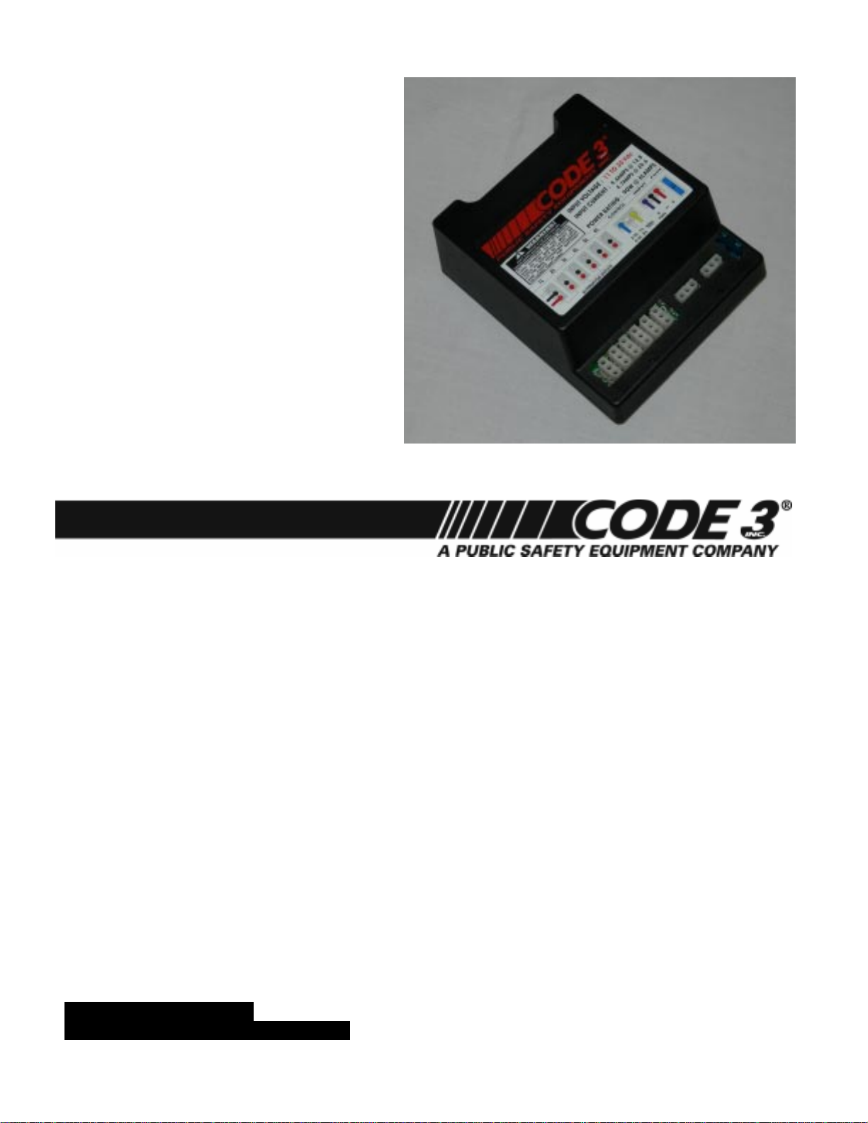
The CPS690 Series Remote Strobe Power Supply represents the latest in state-of-the-art strobe warning
technology. The latest in MOSFET technology and advanced design provide efficient operation, meaning
superior performance, reliability and long life. The use of intelligent microprocessor control allows the Model
CPS690 series to offer more light pattern options and versatility than any other remote system available. The
user may select Double, Triple, Quad, Five Flash or Cycle Flash Patterns. When connected to remote strobe
heads, the CPS690 delivers the highest available level of emergency warning signals.
Standard Features
The CPS690 Remote Strobe Power Supply is available as a 4 strobe Hide-a-way kit as part number
490HCL. The 490HCL comes complete with a CPS690 power supply, four Hide-a-way strobe tubes
and four 30' cables. Refer to CODE 3 manual T07715 for details on installation of the Hide-a-way
strobe tubes. All MODEL CPS690 Remote Strobe Power Supplies have the the following features:
12 AND 24 VDC OPERATION
REVERSE POLARITY PROTECTED
EXTERNAL FUSE PROTECTION
User replaceable 15 AMP fuse.
OUTPUT SHORT CIRCUIT/FLASHTUBE FAILURE PROTECTION
Power supply will shut down when trying to flash any heads that have been shorted.
MULTIPLE USER SELECTABLE FLASH PATTERNS
User may select either Double Flash, Triple Flash, Quad Flash, Five Flash, or Cycle Flash patterns. See
Flash Control Options Section, page 6.
SELECTABLE CONTROL OF OUTLET PAIRS
Allows user to select either alternating outlet sets 1-2, or 3+5- 4+6, or all outlets active (6 Head).
THIS POWER SUPPLY IS NFPA COMPLIANT WHEN USED IN QUAD OR FIVE FLASH MODES. SEE
FIGURE F ON PAGE 8.
Specifications
OPERATING VOLTAGE: 10-30 VDC
POWER: 90 WATTS
ENERGY: 85 JOULES NOMINAL
STANDARD FLASH RATE: EACH STROBE LIGHT OUTLET 70 QUAD FLASHES/MIN.
ALTERNATING PAIRS 140 QUAD FLASHES/MIN.
POWER CONSUMPTION: 8.5 AMPS AVERAGE @ 12.8 VDC (HIGH POWER)
Page 3

!
WARNING!
The use of this or any warning device does not insure that all drivers can or will observe or
react to an emergency warning signal. Never take the right-of-way for granted. It is your
responsibility to be sure you can proceed safely before entering an intersection, driving
against traffic, responding at a high rate of speed, or walking on or around traffic lanes.
The effectiveness of this warning device is highly dependent upon correct mounting and
wiring. Read and follow the manufacturer’s instructions before installing or using this
device. The vehicle operator should insure daily that all features of the device operate
correctly. In use, the vehicle operator should insure the projection of the warning signal is
not blocked by vehicle components (i.e.: open trunks or compartment doors), people,
vehicles, or other obstructions.
This equipment is intended for use by authorized personnel only. It is the user’s responsibility to understand and obey all laws regarding emergency warning devices. The user
should check all applicable city, state and federal laws and regulations.
Public Safety Equipment, Inc., assumes no liability for any loss resulting from the use of
this warning device.
Proper installation is vital to the performance of this warning device and the safe operation of
the emergency vehicle. It is important to recognize that the operator of the emergency
vehicle is under psychological and physiological stress caused by the emergency situation.
The warning device should be installed in such a manner as to: A) Not reduce the output
performance of the system, B) Place the controls within convenient reach of the operator
so that one can operate the system without losing eye contact with the roadway.
Emergency warning devices often require high electrical voltages and/or currents. Properly
protect and use caution around live electrical connections. Grounding or shorting of electrical connections can cause high current arcing, which can cause personal injury and/or
severe vehicle damage, including fire. Do not touch the strobe light tubes, the strobe light
head assemblies or the strobe power supply while the system is in operation. Wait 10
minutes after turning off the power from system before touching any internal componentry.
PROPER INSTALLATION COMBINED WITH OPERATOR TRAINING IN THE PROPER
USE OF EMERGENCY WARNING DEVICES IS ESSENTIAL TO INSURE THE SAFETY
OF EMERGENCY PERSONNEL AND THE PUBLIC.
Unpacking and Pre-installation
Remove the power supply from the box and examine the unit for any transit damage. Report any damage to the
carrier immediately. Inspect the supplied user parts kit, the 490HCL Hide-A-Way Strobe kit should contain:
A. 1 Power/Control Wire Harness Assembly
B. 1 CPS690 Strobe Power Supply
C. 4 30 ft. cables
D. 4 Strobe Tube assemblies with connectors
E. 1 Parts Bag
F. 1 Installation Manual
3
Page 4
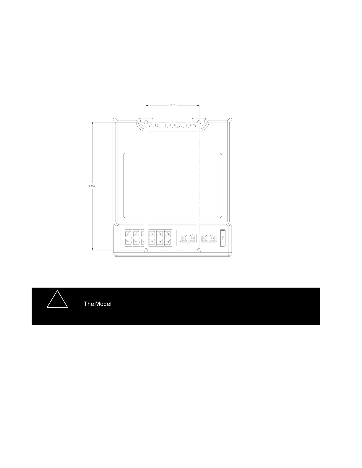
Installation and Mounting
1. First install the CPS690 strobe power suppy in a protected location using the power supply itself as a
template. THE POWER SUPPLY MUST BE MOUNTED TO A METAL SURFACE. Make sure all socket
connectors are easily accesible.
FIGURE A
!
The Model CPS690 Strobe Power Supply is NOT waterproof and should be located in an
area protected from the weather and water.
WARNING!
Wiring
1. Install the strobe light heads in the desired locations.
2. String the 3-conductor cables between the lights and the power supply. Make sure the cable is secure along the
chosen routing inside the vehicle to prevent it from damage by chafing or binding. Be sure to keep the cable away
from engine hot spots.
3. Insert the pins on each end of the conductor cables into the AMP connectors. Each end of these cables has three
pins factory crimped onto each of the three wires. See Figure B on next page for Pin Insertion order.
4
Page 5

Male Amp connector
to be mated with the
Amp output socket on
the Power Supply.
Insert wires with male pins into the
proper locations in the male Amp
connector:
RED WIRE - POSITION 1
BLACK WIRE - POSITION 2
WHITE WIRE - POSITION 3
1
2
3
SHIELD WIRE CONNECT TO
CHASSIS GROUND
FIGURE B
Female Amp
connector.
1
2
3
1
2
3
Amp wire harness
attached to Strobe
light head.
NOTE: IT IS IMPORTANT TO FOLLOW THE CORRECT COLOR CODE
WHEN INSERTING THE PINS INTO THE AMP 3 PIN CONNECTORS.
4. Connect the cables to the strobe light heads.
5. Next, plug the other end of the cable into the Light Head socket (output) on the CPS690 strobe power
supply. The location of the cable for each light head attached to the CPS690 will be determined by the flash
mode selected. (see figure E on page 6)
POWER/CONTROL WIRE HARNESS ASSEMBLY
The Power/Control wire harness assembly consists of two 3 pin AMP style connectors with: 1 red, 1 black, 1
violet, 1 yellow, 1 blue and 1 green (see figure C). The Power/Control harness assembly must be connected to
the power/control socket(s) located on the CPS690 strobe light power supply. Use 18 gauge wire to extend the
control harness wires to a customer supplied switch to complete the installation.
IMPORTANT: To extend the
power (+) and ground (-) wires,
use the following as a guide.
1 to 10 ft. use 16AWG wire
10 to 20 ft. use 14AWG wire
20 to 30 ft. use 12AWG wire
30 to 50 ft. use 10AWG wire
SIMULTANEOUS
FLASH
SIMULTANEOUS
FLASH
123456
3
3
3
3
3
3
2
2
2
2
2
2
1
1
1
1
1
1
ALTERNATING
FLASH
ALTERNATING
FLASH
5
FIGURE C
CONTROL POWER IN
312123
RED (+)
BLK (-)
VIO [HP (NC)]
[LP (+12VDC)]
YEL (+) PATTERN SELECT
GRN (+) 1L/2L
BLU (+) 3/5L or 4/6L
Page 6

1. Connect the Control wires from the Power/Control wire harness assembly to a switch or switches. To select
one of the 12 different flash functions, simply press and release the pattern select switch until the desired
pattern is selected (see Figure F). The flash pattern may also be selected remotely by the operator by connecting a Normally Open (NO) Momentary Push Button Switch to pin 1 (Yellow Wire) of the control connector.
See Figure D for Control Switch connections. See Figure E for Control Wire combinations.
2. Connect Black wires to a reliable ground.(-)
3. Connect Red Power wires from the Power /Control wire harness assembly to the power source (+) through a
switch and an in-line fuse (15A for 12V operation or 7.5A for 24V operation) for the desired operation per Figure
D or Figure E.
CONTROL & POWER WIRING
FIGURE D
BLU (+)
GRN (+)
SPST ON-OFF
SWITCH
(REAR VIEW)
6 HEAD, ON-OFF, HIGH POWER
BLU (+)
SPDT, CENTER
OFF SWITCH
(REAR VIEW)
SELECTIVE SWITCHING
OF OUTLETS 1 AND 2 (only)
OR
OUTLETS 3/4 AND 5/6 (only)
IN HIGH POWER
123
GRN (+)
123 23
RED (+)
15A FOR 12V
7.5A FOR 24V
15A FOR 12V
7.5A FOR 24V
1
+
123
BLK (-)
RED (+)
BLK (-)
TO POWER
SOURCE
TO POWER
+
SOURCE
BLU (+)
SPST 0N-OFF
SWITCH
(REAR VIEW)
4 OUTLETS ON-OFF SWITCHING
HIGH POWER
321 32
VIO
(HI/LO)
RED (+)
15A FOR 12V
7.5A FOR 24V
DPDT CENTER
OFF SWITCH
OFF SWITCH
(REAR VIEW)
4 HEAD, HIGH-OFF-LOW POWER
CONTROL POWER IN
23132
BLU (+)
RED (+)
15A FOR 12V
7.5A FOR 24V
1
BLK (-)
+
1
BLK (-)
TO POWER
+
SOURCE
TO POWER
SOURCE
6
Page 7

CONTROL POWER IN
FIGURE E
CUSTOMER
SUPPLIED DIODE
1N4700 OR
EQUIVALENT
231 32
BLU (+)
GRN (+)
15A FOR 12V
7.5A FOR 24V
SPDT, CENTER
OFF SWITCH
(REAR VIEW)
1
BLK (-)
RED (+)
TO POWER
+
SOURCE
4 OR 6 OUTLETS ON-OFF HIGH POWER
7
Page 8

FLASH PATTERN SELECTION
L1 L2 L3 L4 L5 FLASH MODE
* ----Quad Flash
- * ---Double Flash
-- * --Cycle Flash 1
-- - * - Quad Flash Slow/Fast
----* Five Flash All Heads
** ---Quad Flash Slow
* - * --Double-Triple Flash
* --* - Double-Double Flash
* ---* Fast Single Flash
- **--Triple Flash
- * - * - Variable flash
- * --* Cycle Flash 2
* Indicated LED is lighted
FIGURE F
FOR NFPA COMPLIANT INSTALLATION, SELECT QUAD
OR FIVE FLASH MODES
WARNING: To achieve the maximum performance from your strobe tubes, do not mix Helix tubes and
Linear Tubes. Run all Helix or all Linear strobe tubes on the odd numbered outputs of the power
supply (1,3,5), and run all of the alternate style tubes on the even numbered outputs. (2,4,6). Mixing
strobe tubes on the even or odd numbered outputs will cause one type to flash brighter than the other
type and will reduce the life expectancy of the brighter flashing tube.
MAINTENANCE
The CPS690 Remote Strobe Power Supply has been designed to provide trouble free service. In case of
difficulty, refer to the Troubleshooting section. Periodic inspection of power supply wiring, and strobe light head
connections for shorted or open wires will assure trouble free operation. The primary cause of short circuits
has been found to be wires passing through firewalls, roofs, etc.
8
Page 9

Troubleshooting
NOTE: DO NOT TAMPER WITH THE POWER SUPPLY. THIS UNIT IS SOLD AS A COMPLETE
MODULE, AND IS NOT DESIGNED FOR FIELD REPAIR. REMOVING THE TOP CASE CAN RESULT
IN ELECTRIC SHOCK AND WILL VOID THE WARRANTY.
All CPS690 Remote Strobe Power Supply units are thoroughly tested before shipment. However,
should you encounter a problem during installation or during the life of the product, refer to the guide
below for information on troubleshooting. In most cases problems that occur will be related either to the
power/control wiring, or to the strobe light head cables that connect them to the strobe power supply.
In the event that the strobe power supply is at fault return the unit to the factory for service.
TROUBLESHOOTING GUIDE
PROBLEM CAUSE
External fuse blows
Light heads do not fire
Incorrect flash pattern
1. Power input wires reversed
2. Power supply failure
3. Incorrect fuse size
1. Cable connections loose at
power supply or light head
2. Cable to light heads damaged and shorting to chassis
3. Cable terminated improperly
in 3 pin AMP connector
4. Bad strobe tube
1. Control harness wiring and
or switches not connected
properly
2. Light heads plugged into
wrong outlet on the power
supply
SOLUTION
1. Check power connections
2. Return for service
3. Replace with a 15A
1. Check all connections
2. Isolate damaged cable by disconnecting
and reconnecting outputs one at a time.
Repair or replace the damaged cable.
(When other heads come back on the one
that is disconnected is the shorted line.)
3. Check wire orientations at 3 pin connectors
4. Replace strobe tube assembly
1. Check wiring/switches. Refer to Table 1
to verify selections.
2. Follow designations on label for outlets
and move to proper outlet.
Flash patterns change
continuously
1. Power Supply is in CYCLE
FLASH mode. Proper operation.
9
1. Brown wire is connected to +VDC. Check
control harness/switches. If CYCLE MODE
is not desired change connections.
Page 10

NOTES
10
Page 11

NOTES
11
Page 12

WARRANTY
This product was tested and found to be operational at the time of manufacture. Provided this
product is installed and operated in accordance with the manufacturer's recommendations, Public
Safety Equipment guarantees the CPS690 for a period of 5 years from the date of purchase or
delivery, whichever is later. Units demonstrated to be defective within the warranty period will be
repaired or replaced at the factory service center at no cost.
Use of a lamp or other electrical load of a wattage higher than installed or recommended by
the factory, or use of inappropriate or inadequate wiring or circuit protection causes this warranty to
become void. Failure or destruction of the product resulting from abuse or unusual use and/or
accidents is not covered by this warranty. Use of non-PSE components and assemblies may
cause damage to the system and/or personal injury, and voids all warranties on PSE systems and
components.
PSE shall in no way be liable for other damages including consequential, indirect or special
damages whether loss is due to negligence or breach of warranty.
PSE MAKES NO OTHER EXPRESS OR IMPLIED WARRANTY INCLUDING, WITHOUT LIMITATION,
WARRANTIES OF FITNESS OR MERCHANTABILITY, WITH RESPECT TO THIS PRODUCT.
PRODUCT RETURNS
In order to provide you with faster service, if you are going to return a product for repair or
replacement*, please contact our factory to obtain a Return Goods Authorization Number (RGA
number) before you ship the product to PSE. Write the RGA number clearly on the package near
the mailing label. Be sure you use sufficient packing materials to avoid damage to the product
being returned while in transit.
*PSE reserves the right to repair or replace product at its discretion. PSE assumes no responsibility or
liability for expenses incurred for the removal and/or reinstallation of products requiring service and/or repair.
NEED HELP? Call our Technical Assistance Hotline - (314) 996-2800
Public Safety Equipment (UK), Ltd. Public Safety Equipment, Inc.
Oldham Road, Rishworth 10986 N. Warson Road
Halifax, West YorkshireENGLAND HX6 4QG St. Louis, Missouri 63114-2029USA
Ph. 0422-824640 Fax 0422-824604 Ph. (314) 426-2700 Fax (314) 426-1337
Code 3 is a registered trademark of Public Safety Equipment, Inc.
CycleFlash is a trademark of Public Safety Equipment, Inc.
Revision 1, 01/07 - Instruction Book Part No. T11444
©2007 Public Safety Equipment, Inc. Printed in USA
 Loading...