

Page 1
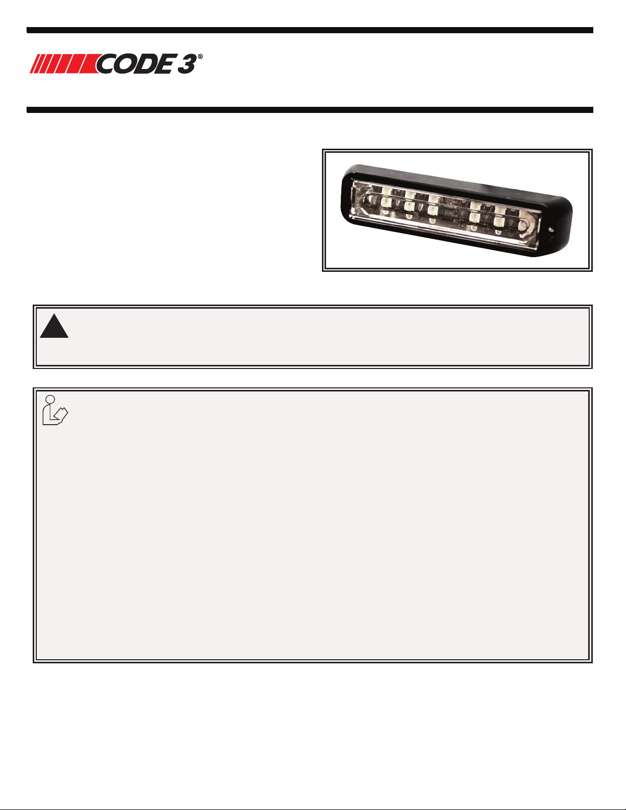
Available in various color combinations, the CD3766
!
Installation and Operation Instructions
CD3766 Directional LED
Directional LED is a surface mount, dual color warning
light that is ideal for a wide variety of auxiliary warning
applications. Featuring a linear optic, 12 high intensity
LEDs (6 per color), 11 fl ash patterns, synchronization
capability and an aluminum housing with encapsulated
electronics, the CD3766 is an extremely bright, versatile
and robust warning light. Each LED color can be controlled
independently.
WARNING!
Failure to install or use this product according to manufacturers recommendations may result in property damage, serious
injury, and/or death to those you are seeking to protect!
Do not install and/or operate this safety product unless you have read and understand the safety
information contained in this manual.
1. Proper installation combined with operator training in the use, care, and maintenance of emergency warning devices are
essential to ensure the safety of you and those you are seeking to protect.
2. Exercise caution when working with live electrical connections.
3. This product must be properly grounded. Inadequate grounding and/or shorting of electrical connections can cause high
current arcing, which can cause personal injury and/or severe vehicle damage, including fi re.
4. Proper placement and installation are vital to the performance of this warning device. Install this product so that output
performance of the system is maximized and the controls are placed within convenient reach of the operator so that s/he
can operate the system without losing eye contact with the roadway.
5. Do not install this product or route any wires in the deployment area of an air bag. Equipment mounted or located in an
air bag deployment area may reduce the effectiveness of the air bag or become a projectile that could cause serious personal injury or death. Refer to the vehicle owner’s manual for the air bag deployment area. It is the responsibility of the
user/operator to determine a suitable mounting location ensuring the safety of all passengers inside the vehicle particularly avoiding areas of potential head impact.
6. It is the responsibility of the vehicle operator to ensure during use that all features of this product work correctly. In use,
the vehicle operator should ensure the projection of the warning signal is not blocked by vehicle components (i.e., open
trunks or compartment doors), people, vehicles or other obstructions.
7. The use of this or any other warning device does not ensure all drivers can or will observe or react to a warning signal.
Never take the right-of-way for granted. It is your responsibility to be sure you can proceed safely before entering an
intersection, driving against traffi c, responding at a high rate of speed, or walking on or around traffi c lanes.
8. This equipment is intended for use by authorized personnel only. The user is responsible for understanding and obeying
all laws regarding warning signal devices. Therefore, the user should check all applicable city, state, and federal laws
and regulations. The manufacturer assumes no liability for any loss resulting from the use of this warning device.
920-1003-00 Rev. A Page 1 of 5
Page 2
CONTENTS:
1 Light Head
2 Screws
1 Installation Guide
1 Mounting Gasket
1 Flange
SPECIFICATIONS:
Important! This unit is a safety device and it must be
connected to its own separate, fused power point to assure its
continued operation should any other electrical accessory fail.
Input Voltage 12-24VDC
Work Current 0.9A Max @ DC12V
0.5A Max @ DC24V
Physical H x W x L 1.07 in x 1.48 in x 6.38 in
2.76 cm x 3.75 cm x 16.2 cm
Ship Weight 0.463 lb (0.21 Kg)
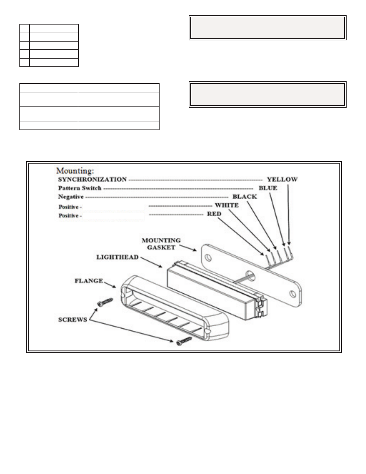
Mounting:
LED Color 1 & Color 3
LED Color 2 & Color 4
Caution: When drilling into any vehicle surface, make sure the
area is free from any electrical wires, fuel lines, vehicle upholstery,
etc. that could be damaged
Wire:
RED: Positive, Colors 2 & 4 (need to add 5A fuse)
WHITE: Positive, Colors 1 & 3 (need to add 5A fuse)
BLACK: Negative
BLUE: Pattern Switch
Phase Operation:
Phase 1 (Ph1) fl ashes simultaneously with Ph1
Phase 2 (Ph2) fl ashes simultaneously with Ph2
Ph1 alternates with Ph2
(Up to 8 units can be Synchronized)
YELLOW: Synchronized Function
(Up to 8 units can be Synchronized)
Apply BLUE TO BLACK wire:
-Less than 1 sec. for next pattern
Operation Environment:
Ambient Temperature: -30 to 50°C
920-1003-00 Rev. A Page 2 of 5
-Between 1-3 sec for previous pattern
-Between 3-5 sec. for factory default (P64)
-More than 5 sec. for turn off
Page 3

CD3766 Flash Pattern
SAE J595 CA T13 ECE R65
LED Color
LED Color
Pattern
White Wire
1- Default 1 SAE/T13 Single 75FPM Ph1 Color 1 Synchronous Color 3 yes Class 1 Class 1 Class 1 Class 1 Class B Class B Class B N/C N/C N/C
1
2
3
4
LED Color
1 & 3
2 & 4
Red Wire
2 2 SAE/T13 Single 75FPM Ph2 Color 1 Synchronous Color 3 yes Class 1 Class 1 Class 1 Class 1 Class B Class B Class B N/C N/C N/C
3 3 SAE/T13 Single 75FPM Ph1 Color 1 Alternately Color 3 yes N/C N/C N/C N/C N/C N/C N/C N/C N/C N/C
4 4 SAE/T13 Single 75FPM Ph2 Color 1 Alternately Color 3 yes N/C N/C N/C N/C N/C N/C N/C N/C N/C N/C
1-Default 5 SAE/T13 Single 75FPM Ph1 Color 2 Synchronous Color 4 yes Class 1 Class 1 Class 1 Class 1 Class B Class B Class B N/C N/C N/C
2 6 SAE/T13 Single 75FPM Ph2 Color 2 Synchronous Color 4 yes Class 1 Class 1 Class 1 Class 1 Class B Class B Class B N/C N/C N/C
3 7 SAE/T13 Single 75FPM Ph1 Color 2 Alternately Color 4 yes N/C N/C N/C N/C N/C N/C N/C N/C N/C N/C
4 8 SAE/T13 Single 75FPM Ph2 Color 2 Alternately Color 4 yes N/C N/C N/C N/C N/C N/C N/C N/C N/C N/C
5 12 Single 375 Ph1 Color 1 Synchronous Color 3 yes N/C N/C N/C N/C N/C N/C N/C N/C N/C N/C
6 13 Single 375 Ph2 Color 1 Synchronous Color 3 yes N/C N/C N/C N/C N/C N/C N/C N/C N/C N/C
7 14 Single 375 Ph1 Color 1 Alternately Color 3 yes N/C N/C N/C N/C N/C N/C N/C N/C N/C N/C
8 15 Single 375 Ph2 Color 1 Alternately Color 3 yes N/C N/C N/C N/C N/C N/C N/C N/C N/C N/C
5 16 Single 375 Ph1 Color 2 Synchronous Color 4 yes N/C N/C N/C N/C N/C N/C N/C N/C N/C N/C
6 17 Single 375 Ph2 Color 2 Synchronous Color 4 yes N/C N/C N/C N/C N/C N/C N/C N/C N/C N/C
7 18 Single 375 Ph1 Color 2 Alternately Color 4 yes N/C N/C N/C N/C N/C N/C N/C N/C N/C N/C
8 19 Single 375 Ph2 Color 2 Alternately Color 4 yes N/C N/C N/C N/C N/C N/C N/C N/C N/C N/C
9 23 SAE/T13 Double 75FPM Ph1 Color 1 Synchronous Color 3 yes Class 1 Class 1 Class 1 Class 1 Class B Class B Class B N/C N/C N/C
10 24 SAE/T13 Double 75FPM Ph2 Color 1 Synchronous Color 3 yes Class 1 Class 1 Class 1 Class 1 Class B Class B Class B N/C N/C N/C
11 25 SAE/T13 Double 75FPM Ph1 Color 1 Alternately Color 3 yes N/C N/C N/C N/C N/C N/C N/C N/C N/C N/C
12 26 SAE/T13 Double 75FPM Ph2 Color 1 Alternately Color 3 yes N/C N/C N/C N/C N/C N/C N/C N/C N/C N/C
9 27 SAE/T13 Double 75FPM Ph1 Color 2 Synchronous Color 4 yes
10 28 SAE/T13 Double 75FPM Ph2 Color 2 Synchronous Color 4 yes Class 1 Class 1 Class 1 Class 1 Class B Class B Class B N/C N/C N/C
11 29 SAE/T13 Double 75FPM Ph1 Color 2 Alternately Color 4 yes N/C N/C N/C N/C N/C N/C N/C N/C N/C N/C
12 30 SAE/T13 Double 75FPM Ph2 Color 2 Alternately Color 4 yes N/C N/C N/C N/C N/C N/C N/C N/C N/C N/C
13 34 ECER65 Double 120FPM Ph1 Color 1 Synchronous Color 3 yes Class 1 Class 1 Class 1 Class 1 N/C N/C N/C Class 1 Class 1 Class 1
14 35 ECER65 Double 120FPM Ph2 Color 1 Synchronous Color 3 yes Class 1 Class 1 Class 1 Class 1 N/C N/C N/C Class 1 Class 1 Class 1
15 36 ECER65 Double 120FPM Ph1 Color 1 Alternately Color 3 no N/C N/C N/C N/C N/C N/C N/C N/C N/C N/C
16 37 ECER65 Double 120FPM Ph2 Color 1 Alternately Color 3 no N/C N/C N/C N/C N/C N/C N/C N/C N/C N/C
13 38 ECER65 Double 120FPM Ph1 Color 2 Synchronous Color 4 no Class 1 Class 1 Class 1 Class 1 N/C N/C N/C Class 1 Class 1 Class 1
14 39 ECER65 Double 120FPM Ph2 Color 2 Synchronous Color 4 no Class 1 Class 1 Class 1 Class 1 N/C N/C N/C Class 1 Class 1 Class 1
15 40 ECER65 Double 120FPM Ph1 Color 2 Alternately Color 4 no N/C N/C N/C N/C N/C N/C N/C N/C N/C N/C
16 41 ECER65 Double 120FPM Ph2 Color 2 Alternately Color 4 N/C N/C N/C N/C N/C N/C N/C N/C N/C N/C
1 & 3
LED Color
2 & 4
White and
Red Wire
9
10
11
20
21
22
31
32
33
42
43
44
CD3766 FLASH PATTERN SYNC RED AMBER BLUE WHITE RED AMBER BLUE RED AMBER BLUE
SAE/T13 Single 75FPM (Color 1 Synchronous Color 3)
Alternately (Color 2 Synchronous Color 4)
SAE/T13 Single 75FPM (Color 1 Synchronous Color 4)
Alternately (Color 2 Synchronous Color 3)
SAE/T13 Single 75FPM (Color 1 Alternately Color 2) Alternately (Color 3 Alternately Color 4)
Single 375 (Color 1 Synchronous Color 3) Alternately (Color 2
Synchronous Color 4)
Single 375 (Color 1 Synchronous Color 4) Alternately (Color 2
Synchronous Color 3)
Single 375 (Color 1 Alternately Color 2) Alternately (Color 3
Alternately Color 4)
SAE/T13 Double 75FPM (Color 1 Synchronous Color 3)
Alternately (Color 2 Synchronous Color 4)
SAE/T13 Double 75FPM (Color 1 Synchronous Color 4)
Alternately (Color 2 Synchronous Color 3)
SAE/T13 Double 75FPM (Color 1 Alternately Color 2) Alternately (Color 3 Alternately Color 4)
ECER65 Double 120FPM (Color 1 Synchronous Color 3)
Alternately (Color 2 Synchronous Color 4)
ECER65 Double 120FPM (Color 1 Synchronous Color 4)
Alternately (Color 2 Synchronous Color 3)
ECER65 Double 120FPM (Color 1 Alternately Color 2) Alternately (Color 3 Alternately Color 4)
yes N/C N/C N/C N/C N/C N/C N/C N/C N/C N/C
yes N/C N/C N/C N/C N/C N/C N/C N/C N/C N/C
yes N/C N/C N/C N/C N/C N/C N/C N/C N/C N/C
yes N/C N/C N/C N/C N/C N/C N/C N/C N/C N/C
yes N/C N/C N/C N/C N/C N/C N/C N/C N/C N/C
yes N/C N/C N/C N/C N/C N/C N/C N/C N/C N/C
Class 1 Class 1 Class 1 Class 1 Class B Class B Class B N/C N/C N/C
yes N/C N/C N/C N/C N/C N/C N/C N/C N/C N/C
yes N/C N/C N/C N/C N/C N/C N/C N/C N/C N/C
yes N/C N/C N/C N/C N/C N/C N/C N/C N/C N/C
N/C N/C N/C N/C N/C N/C N/C N/C N/C N/C
N/C N/C N/C N/C N/C N/C N/C N/C N/C N/C
N/C N/C N/C N/C N/C N/C N/C N/C N/C N/C
920-1003-00 Rev. A Page 3 of 5
Page 4

SAE J595 CA T13 ECE R65
LED Color
LED Color
Pattern
White Wire
5
6
7
8 78
9 79
10 80
11 81
N/A 29 29 82 OFF no N/C N/C N/C N/C N/C N/C N/C N/C N/C N/C
LED Color
1 & 3
17 45 SAE/T13 Triple 75FPM Ph1 Color 1 Synchronous Color 3 yes Class 1 Class 1 Class 1 Class 1 Class B Class B Class B N/C N/C N/C
18 46 SAE/T13 Triple 75FPM Ph2 Color 1 Synchronous Color 3 yes Class 1 Class 1 Class 1 Class 1 Class B Class B Class B N/C N/C N/C
19 47 SAE/T13 Triple 75FPM Ph1 Color 1 Alternately Color 3 yes N/C N/C N/C N/C N/C N/C N/C N/C N/C N/C
20 48 SAE/T13 Triple 75FPM Ph2 Color 1 Alternately Color 3 yes N/C N/C N/C N/C N/C N/C N/C N/C N/C N/C
21 56 SAE/T13 Quad 75FPM Ph1 Color 1 Synchronous Color 3 yes Class 1 Class 1 Class 1 Class 1 Class B Class B Class B N/C N/C N/C
22 57 SAE/T13 Quad 75FPM Ph2 Color 1 Synchronous Color 3 yes Class 1 Class 1 Class 1 Class 1 Class B Class B Class B N/C N/C N/C
23 58 SAE/T13 Quad 75FPM Ph1 Color 1 Alternately Color 3 yes N/C N/C N/C N/C N/C N/C N/C N/C N/C N/C
24 59 SAE/T13 Quad 75FPM Ph2 Color 1 Alternately Color 3 yes N/C N/C N/C N/C N/C N/C N/C N/C N/C N/C
25 67
26 68
27 69 ECER65/SAE Quad 120FPM Ph1 Color 1 Alternately Color 3 yes N/C N/C N/C N/C N/C N/C N/C N/C N/C N/C
28 70 ECER65/SAE Quad 120FPM Ph2 Color 1 Alternately Color 3 yes N/C N/C N/C N/C N/C N/C N/C
2 & 4
Red Wire
17 49 SAE/T13 Triple 75FPM Ph1 Color 2 Synchronous Color 4 yes Class 1 Class 1 Class 1 Class 1 Class B Class B Class B N/C N/C N/C
18 50 SAE/T13 Triple 75FPM Ph2 Color 2 Synchronous Color 4 yes Class 1 Class 1 Class 1 Class 1 Class B Class B Class B N/C N/C N/C
19 51 SAE/T13 Triple 75FPM Ph1 Color 2 Alternately Color 4 yes N/C N/C N/C N/C N/C N/C N/C N/C N/C N/C
20 52 SAE/T13 Triple 75FPM Ph2 Color 2 Alternately Color 4 yes N/C N/C N/C N/C N/C N/C N/C N/C N/C N/C
21 60 SAE/T13 Quad 75FPM Ph1 Color 2 Synchronous Color 4 yes Class 1 Class 1 Class 1 Class 1 Class B Class B Class B N/C N/C N/C
22 61 SAE/T13 Quad 75FPM Ph2 Color 2 Synchronous Color 4 yes Class 1 Class 1 Class 1 Class 1 Class B Class B Class B N/C N/C N/C
23 62 SAE/T13 Quad 75FPM Ph1 Color 2 Alternately Color 4 yes N/C N/C N/C N/C N/C N/C N/C N/C N/C N/C
24 63 SAE/T13 Quad 75FPM Ph2 Color 2 Alternately Color 4 yes N/C N/C N/C N/C N/C N/C N/C N/C N/C N/C
25 71
26 72
27 73 ECER65/SAE Quad 120FPM Ph1 Color 2 Alternately Color 4 yes N/C N/C N/C N/C N/C N/C N/C N/C N/C N/C
28 74 ECER65/SAE Quad 120FPM Ph2 Color 2 Alternately Color 4 yes N/C N/C N/C N/C N/C N/C N/C N/C N/C N/C
1 & 3
LED Color
2 & 4
White and
Red Wire
53
54
55
64-DEFAULT
65
66
75
76
77
CD3766 FLASH PATTERN SYNC RED AMBER BLUE WHITE RED AMBER BLUE RED AMBER BLUE
SAE/T13 Triple 75FPM (Color 1 Synchronous Color 3) Alternately (Color 2 Synchronous Color 4)
SAE/T13 Triple 75FPM (Color 1 Synchronous Color 4) Alternately (Color 2 Synchronous Color 3)
SAE/T13 Triple 75FPM (Color 1 Alternately Color 2) Alternately (Color 3 Alternately Color 4)
SAE/T13 Quad 75FPM (Color 1 Synchronous Color 3) Alternately (Color 2 Synchronous Color 4)
SAE/T13 Quad 75FPM (Color 1 Synchronous Color 4) Alternately (Color 2 Synchronous Color 3)
SAE/T13 Quad 75FPM (Color 1 Alternately Color 2) Alternately (Color 3 Alternately Color 4)
ECER65/SAE Quad 120FPM Ph1 Color 1 Synchronous
Color 3
ECER65/SAE Quad 120FPM Ph2 Color 1 Synchronous
Color 3
ECER65/SAE Quad 120FPM Ph1 Color 2 Synchronous
Color 4
ECER65/SAE Quad 120FPM Ph2 Color 2 Synchronous
Color 4
ECER65/SAE Quad 120FPM (Color 1 Synchronous Color 3)
Alternately (Color 2 Synchronous Color 4)
ECER65/SAE Quad 120FPM (Color 1 Synchronous Color 4)
Alternately (Color 2 Synchronous Color 3)
ECER65/SAE Quad 120FPM (Color 1 Alternately Color 2)
Alternately (Color 3 Alternately Color 4)
Modulation (Color 1 Synchronous Color 3) Alternately (Color 2
Synchronous Color 4)
2 Double,2 Quad (Color 1 Synchronous Color 3) Alternately
(Color 2 Synchronous Color 4)
4 Single,2 Triple (Color 1 Synchronous Color 3) Alternately
(Color 2 Synchronous Color 4)
1Doube 1Triple 1Quad (Color 1 Synchronous Color 3) Alternately (Color 2 Synchronous Color 4)
yes N/C N/C N/C N/C N/C N/C N/C N/C N/C N/C
yes N/C N/C N/C N/C N/C N/C N/C N/C N/C N/C
yes N/C N/C N/C N/C N/C N/C N/C N/C N/C N/C
yes N/C N/C N/C N/C N/C N/C N/C N/C N/C N/C
yes N/C N/C N/C N/C N/C N/C N/C N/C N/C N/C
yes N/C N/C N/C N/C N/C N/C N/C N/C N/C N/C
yes Class 1 Class 1 Class 1 Class 2 N/C N/C N/C Class 1 Class 1 Class 1
yes Class 1 Class 1 Class 1 Class 2 N/C N/C N/C Class 1 Class 1 Class 1
N/C N/C N/C
yes Class 1 Class 1 Class 1 Class 2 N/C N/C N/C Class 1 Class 1 Class 1
yes Class 1 Class 1 Class 1 Class 2 N/C N/C N/C Class 1 Class 1 Class 1
yes N/C N/C N/C N/C N/C N/C N/C N/C N/C N/C
yes N/C N/C N/C N/C N/C N/C N/C N/C N/C N/C
yes N/C N/C N/C N/C N/C N/C N/C N/C N/C N/C
no N/C N/C N/C N/C N/C N/C N/C N/C N/C N/C
no N/C N/C N/C N/C N/C N/C N/C N/C N/C N/C
no N/C N/C N/C N/C N/C N/C N/C N/C N/C N/C
no N/C N/C N/C N/C N/C N/C N/C N/C N/C N/C
920-1003-00 Rev. A Page 4 of 5
Page 5
10986 North Warson Road
St. Louis, MO 63114
Customer Service
(314) 426-2700
cs-c3@code3esg.com
www.code3esg.com
A Division of ESG
|
www.eccogroup.com
Trouble Shooting
The CD3766 series has been factory tested and approved. If the functions of the device fail, please check the following:
1. After connecting with the power supply, be sure that the power source end is joined correctly. Make sure there is not a short circuit.
2. Plug in the device; ensure the LED power switch is on.
3. Press the Pattern Switch to ensure “OFF” pattern is not selected. If the blue wire touches the black wire over 5 seconds, it would switch to the
OFF pattern. It will light up again when the blue wire touches the black wire continuously for less than 1 second.
Manufacturer Limited Warranty and Limitation of Liability:
Manufacturer warrants that on the date of purchase this product will conform to Manufacturer’s specications for this product (which
are available from the Manufacturer upon request), and Manufacturer further warrants that this product is free from defects in materials and workmanship. This Limited Warranty extends for thirty-six (36) months from the date of purchase. Other warranties may apply,
call Manufacturer for details. Manufacturer will, at its discretion, repair or replace any product found by the Manufacturer to be defective and subject to this Limited Warranty.
DAMAGE TO PARTS OR PRODUCTS RESULTING FROM TAMPERING, ACCIDENT, ABUSE, MISUSE, NEGLIGENCE, UNAPPROVED MODIFICATIONS, FIRE OR OTHER HAZARD; IMPROPER INSTALLATION OR OPERATION; OR NOT BEING MAINTAINED IN ACCORDANCE WITH THE MAINTENANCE PROCEDURES SET FORTH IN MANUFACTURER’S INSTALLATION AND
OPERATING INSTRUCTIONS VOIDS THIS LIMITED WARRANTY.
ORAL STATEMENTS OR REPRESENTATIONS ABOUT THE PRODUCT WHICH MAY HAVE BEEN MADE BY SALESPEOPLE,
DEALERS, AGENTS OR OTHER MANUFACTURER’S REPRESENTATIVES DO NOT CONSTITUTE WARRANTIES. THIS LIMITED
WARRANTY MAY NOT BE AMENDED, MODIFIED, OR ENLARGED EXCEPT BY A WRITTEN AGREEMENT SIGNED BY AN AUTHORIZED OFFICIAL OF MANUFACTURER WHICH EXPRESSLY REFERS TO THIS LIMITED WARRANTY.
Exclusion of Other Warranties: MANUFACTURER MAKES NO OTHER WARRANTIES, EXPRESS OR IMPLIED. THE IMPLIED
WARRANTIES FOR MERCHANTABILITY OR FITNESS FOR A PARTICULAR PURPOSE ARE HEREBY EXCLUDED AND SHALL
NOT APPLY TO THE PRODUCT. BUYER’S SOLE AND EXCLUSIVE REMEDY IN CONTRACT, TORT, OR UNDER ANY OTHER
THEORY AGAINST MANUFACTURER REGARDING THE PRODUCT AND ITS USE SHALL BE THE REPLACEMENT OR REPAIR
OF THE PRODUCT AS DESCRIBED ABOVE.
Limitation of Liability: IN THE EVENT OF LIABILITY FOR DAMAGES ARISING OUT OF THIS LIMITED WARRANTY OR ANY
OTHER CLAIM RELATED TO THE MANUFACTURER’S PRODUCTS, MANUFACTURER’S LIABILITY FOR DAMAGES SHALL BE
LIMITED TO THE AMOUNT PAID FOR THE PRODUCT AT THE TIME OF THE ORIGINAL PURCHASE. IN NO EVENT SHALL MANUFACTURER BE LIABLE FOR LOST PROFITS, THE COST OF SUBSTITUTE EQUIPMENT OR LABOR, PROPERTY DAMAGE,
OR OTHER SPECIAL, CONSEQUENTIAL, OR INCIDENTAL DAMAGES BASED UPON ANY CLAIM FOR BREACH OF CONTRACT,
IMPROPER INSTALLATION, NEGLIGENCE, OR OTHER CLAIM, EVEN IF MANUFACTURER OR A MANUFACTURER’S REPRESENTATIVE HAS BEEN ADVISED OF THE POSSIBILITY OF SUCH DAMAGES. MANUFACTURER SHALL HAVE NO FURTHER
OBLIGATION OR LIABILITY WITH RESPECT TO THE PRODUCT OR ITS SALE, OPERATION AND USE, AND MANUFACTURER
NEITHER ASSUMES NOR AUTHORIZES THE ASSUMPTION OF ANY OTHER OBLIGATION OR LIABILITY IN CONNECTION WITH
SUCH PRODUCT.
This Limited Warranty denes specic legal rights. You may have other legal rights, which vary from state to state. Some states do not
allow the exclusion or limitation of incidental or consequential damages.
920-1003-00 Rev. A Page 5 of 5
 Loading...