

Page 1
INSTALLATION MANUAL
CONTENTS: Introduction ............................................................................. ....................2
Installation, Mounting, & Wiring .............................................. ................3-5
Wiring Diagram Package 1 .................................................... ....................6
Wiring Diagram Package 2 .................................................... ....................7
Wiring Diagram Package 3 .................................................... ....................8
Wiring Diagram Package 4 .................................................... ....................9
Wiring Diagram Package 5 .................................................... ...................10
Functionality-Flash Pattern Selection ..................................................11-12
Notes:...................................................................................................13-15
Warranty ..................................................................................................16
For future reference record your product's serial no. here __________________________________________
IMPORTANT:
Read all instructions and warnings before installing and using.
This manual must be delivered to the end user of this equipment.
INSTALLER:
Page 2

Introduction
The CELS™ Coordinated Emergency Lighting System (hereafter called "the system") is designed to be mounted in the interior of the ve-
hicle and can control all of the emergency vehicle lighting on your slick top vehicle to ash synchronously with the programmability of a CC
lightbar! The system can also dim the entire emergency lighting system.
CELS provides greater control of your lights to match your situational needs. CELS is available in 5 undercover lighting packages.
Product Features
Packages
• Packages 1-4 include 4 types of lighting equipment and a control box.
• Package 5 includes 3 types of lighting equipment and a control box.
• Control box can be wired to any switching type system.
• NarrowStik™ functionality with exterior rear window light (Citadel).
• Dimming capability for all lighting equipment.
• Synchronous capability for all lighting equipment.
• For use on Ford PI Utility and Chevy Tahoe vehicles.
• CELS Flash Patterns work independently of a light bar, if one is installed on your vehicle.
CELS Package LED Lighting Components
• SuperVisor U® with Torus LEDs mounts inside windshield with no drilling.
• Citadel™ LED Exterior Lighting Systems ts under the Rear Spoiler with no drilling.
• PAR36 Fog Light with 7 LEDs per Head (4.25" diameter).
• XT4S LED Light heads (4.52” wide).
Specications
• Control Box Dimensions: 4 ¾” W x 8 ½” L x 1 7/8” H
• Control Box Weight: 1 lb.
• 12 Volts
• 5 Year LED Warranty
• 5 Year CELS Control Box Warranty
WARNING!
The use of this or any warning device does not ensure that all drivers can or will observe or react to an emergency
warning signal. Never take the right-of-way for granted. It is your responsibility to be sure you can proceed safely
before entering an intersection, driving against trafc, responding at a high rate of speed, or walking on or around
trafc lanes. The effectiveness of this warning device is highly dependent upon correct mounting and wiring. Read
and follow the manufacturer’s instructions before installing or using this device. The vehicle operator should insure
daily that all features of the device operate correctly. In use, the vehicle operator should insure the projection of the
warning signal is not blocked by vehicle components (i.e.: open trunks or compartment doors), people, vehicles, or
other obstructions. This equipment is intended for use by authorized personnel only. It is the user’s responsibility to
understand and obey all laws regarding emergency warning devices. The user should check all applicable city, state
and federal laws and regulations. Code 3, Inc., assumes no liability for any loss resulting from the use of this warning
device. Proper installation is vital to the performance of this warning device and the safe operation of the emergency
vehicle. It is important to recognize that the operator of the emergency vehicle is under psychological and physiological
stress caused by the emergency situation. The warning device should be installed in such a manner as to: A) Not
reduce the output performance of the system, B) Place the controls within convenient reach of the operator so that he
can operate the system without losing eye contact with the roadway. Emergency warning devices often require high
electrical voltages and/or currents. Properly protect and use caution around live electrical connections. Grounding or
shorting of electrical connections can cause high current arcing, which can cause personal injury and/or severe vehicle
damage, including re. Driver and/or passenger air bags (SRS) will affect the way equipment should be mounted. This
device should be mounted by permanent installation and within the zones specied by the vehicle manufacturer, if any.
Any device mounted in the deployment area of an air bag will damage or reduce the effectiveness of the air bag and
may damage or dislodge the device. Installer must be sure that this device, its mounting hardware and electrical supply
wiring does not interfere with the air bag or the SRS wiring or sensors. Mounting the unit inside the vehicle by a method
other than permanent installation is not recommended as unit may become dislodged during swerving, sudden braking
or collision. Failure to follow instructions can result in personal injury. PROPER INSTALLATION COMBINED WITH
OPERATOR TRAINING IN THE PROPER USE OF EMERGENCY WARNING DEVICES IS ESSENTIAL TO INSURE
THE SAFETY OF EMERGENCY PERSONNEL AND THE PUBLIC.
WARNING!
Any electronic device may create or be affected by electromagnetic interference. After installation of any electronic
device operate all equipment simultaneously to insure that operation is free of interference. Never power emergency
warning equipment from the same circuit or share the same grounding circuit with radio communication equipment.
All devices should be mounted in accordance with the manufacturer's instructions and securely fastened to vehicle
elements of sufcient strength to withstand the forces applied to the device.
2
Page 3
Installation Instructions
Mount the System Box using customer supplied screws in the (4) slots provided in the housing's base. Note: This box SHOULD NOT be mounted
on the exterior of the vehicle!
This unit must be mounted within the interior passenger compartment of the vehicle only. It is not intended for use in exterior applica-
tions. All devices should be mounted in accordance with the manufacturer’s instructions and securely fastened to vehicle elements of
sufcient strength to withstand the forces applied to the device. Driver and/or passenger air bags (SRS) will affect the way equipment
should be mounted. This device should be mounted by permanent installation and within the zones specied by the vehicle manufacturer, if any. Any device mounted in the deployment area of an air bag will damage or reduce the effectiveness of the air bag and may
WARNING!
damage or dislodge the device. Installer must be sure that this device, its mounting hardware and electrical supply wiring does not
interfere with the air bag or the SRS wiring or sensors. Mounting the unit inside the vehicle by a method other than permanent installation is not recommended as unit may become dislodged during swerving, sudden braking or collision. Failure to follow instructions can
result in personal injury.
WARNING!
Utilizing non-factory supplied screws and/or mounting brackets and/or the improper
number of screws may result in loss of warranty coverage on the equipment.
Wiring Instructions
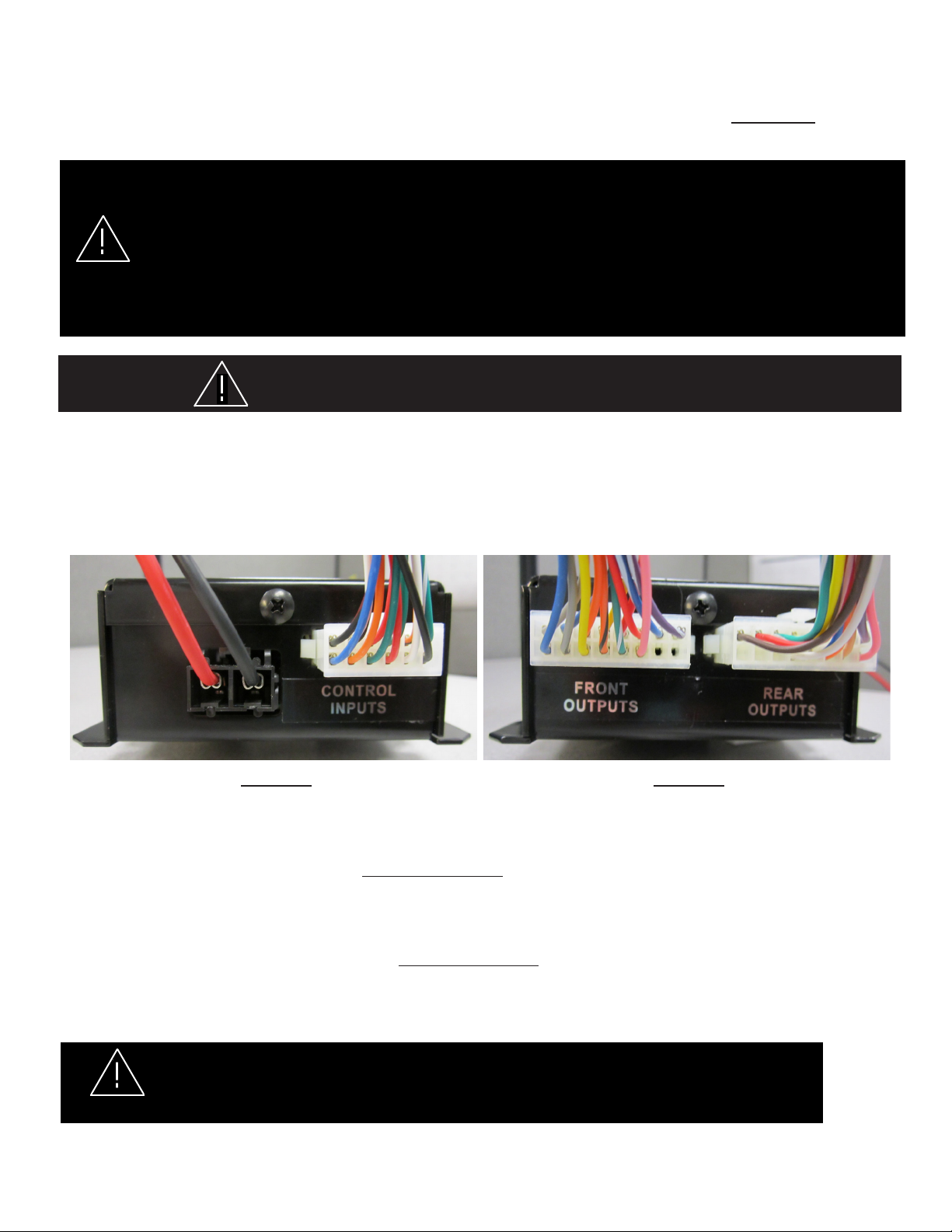
See Figure-1 for the wiring harness connection locations of the Control Input Wires and the main power and ground wires. See Figure-2 for the Front
Output Wires, and the Rear Output Wires. Wire the system based on the wiring diagrams for the individual package ordered as shown on pages 6, 7,
8, 9 & 10. The power and ground should be wired using 12 gage wire and 12 gage butt splices with a 20 amp fuse on the power wire. All of the Input
and the Front and Rear Output wires are 22 gage and should be connected with 22 gage butt splices.
Figure-1 Figure-2
Wiring the Individual Dual Color XT4 & PAR36 Light Heads
The CELS Dual Color XT4 & PAR36 Light Heads are "STEADY BURN ONLY" light heads and rely on the CELS Controller for controlling ash pat-
terns. The CELS Dual Color XT4 & PAR36 Light Heads have (3) control wires, (2) Power wires and (1) Ground Wire. The power wire colors match the
colors of the LEDs in the light heads. The Ground wire is always black. NOTE: See wire color chart on page 5 for individual wire colors.
Wiring the Individual Single Color XT4 & PAR36 Light Heads
The CELS Single Color XT4 & PAR36 Light Heads are also "STEADY BURN ONLY" light heads and rely on the CELS Controller for controlling ash
patterns. The CELS Single Color XT4 & PAR36 Light Heads have only (2) control wires, (1) Power wire which is Red and (1) Ground Wire which is
Black.
DO NOT APPLY 12 VOLTS DIRECTLY TO THE CELS BOX OUTPUT WIRES! THE CELS CC BOARD OR
LIGHT HEADS COULD BE DAMAGED BY APPLYING 12 VOLTS TO THE CC OUTPUTS!
WARNING!
3
Page 4

General Wiring
CELS Wiring
• Read through the wiring diagram for the purchased system prior to the installation and become fully familiar with it to be sure all of the connections
will be made as needed for correct system operation. If there are any questions or problems call our Technical Assistance HOTLINE (314) 996-2800.
• Verify before nal connections are made that Front Output wires are connected to front outputs and Rear Output wires are connected to rear outputs
before crimping the connections.
• Verify that the Front and Rear CELS Output Harness Plugs are in their correct locations See Figure 2 on page 3 (The plugs are labeled as to their
function). If they have been unplugged they can be switched by accident!
• The majority of the wire colors from the CELS Box Front and Rear Output wires to the Front Device Outputs (Full or Half SuperVisor ) and Rear
Device Outputs (Dual Color and Single Color Citadel) match up color to color. Some wire color shades may vary slightly. The Package 5 System
individual device output wires are all customer supplied and dependent on the customer provided wire colors.
• For the XT4 and PAR36 front light head wire colors see wire color chart on page 5 for individual wire colors.
• The main power and ground wires should be connected directly to the vehicle's battery and not to an auxiliary vehicle connection and must be fused
properly. See wiring diagram for the purchased package. Packages 1 - 4 will have an average current draw of 12 - 15A and a maximum of 20A.
• After all programming is complete attach the Black/Red wire to ground to avoid accidental ash pattern/program changes.
• If you require a CA Title 13 Steady Red Light Head feature, the Brown/White wire may be substituted in place of any of the CELS Output Wires
to provide the desired steady burn light head. Note: DO NOT COMBINE THE BROWN/WHITE WIRE WITH ANY OF THE OUTPUT WIRES.
General Wiring Best Practices
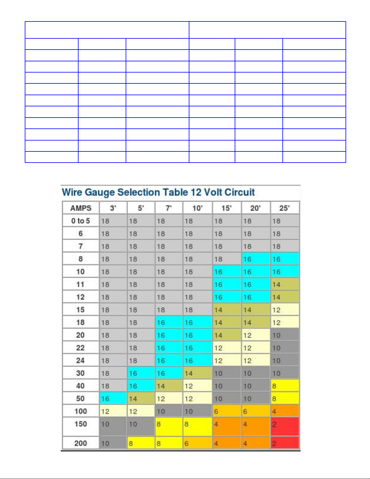
• Larger wires and tight connections will provide longer service life for components. Follow the AWG Table on page 5 for proper wiring gauges based
on length of wire run.
• For high current wires it is highly recommended that terminal blocks or soldered connections be used with heat shrink tubing to protect the connec-
tions.
• Do not use insulation displacement (e.g. 3M® Scotchlock type) connectors.
• Route wiring using grommets and sealant when passing through compartment walls.
• High ambient temperatures (e.g. under hood) will signicantly reduce the current carrying capacity of wires, fuses, and circuit breakers. Use "SXL"
type wire in engine compartment.
• All wiring should conform to the minimum wire size and other recommendations of the wire manufacturer and be protected from moving parts and
hot surfaces.
• Looms, grommets, cable ties, and similar installation hardware should be used to anchor and protect all wiring.
• Fuses or circuit breakers should be located as close to the power takeoff points as possible and properly sized to protect the wiring and devices
• The installer should install a fuse sized to approximately 125% of the maximum Amp capacity in the supply line to protect against short circuits. For
example, a 30 Amp fuse should carry a maximum of 24 Amps.
• DO NOT USE 1/4" DIAMETER GLASS FUSES AS THEY ARE NOT SUITABLE FOR CONTINUOUS DUTY IN SIZES ABOVE 15 AMPS!
• Circuit breakers are very sensitive to high temperatures and can "false trip" when mounted in hot environments or operated close to their capacity.
Ground Connections
• Ground terminations should be made to substantial chassis components, preferably directly to the vehicle battery. Some OEM provided ground
points are not sufcient to provide a proper ground. If in doubt, check to verify the ground with a Multi Meter.
• If Chassis Ground must be used, connection points should be clean and have paint or coatings removed to insure a good tight ground connection.
The gage of the grounding wire must match or exceed the AWG Table shown on page 5.
• Avoid stacking multiple ground connections to one ground source.
• Verify that hardware, screws, bolts, washers, etc. will provide a sufcient ground connection.
Splicing Connections
• Use the correct wire stripper to be sure all strands of the wires remain intact and will provide sufcient electrical current capacity.
• Do not under strip or over strip the wire as it could prevent proper connections or leave bare wiring exposed for potential short circuits.
• Use appropriate crimping pliers to insure good connections.
• Always use properly sized connectors/terminals appropriate to the wire gage being used (Butt Splices, Fork Terminals, Ring Terminals, & etc.).
• Use wire of sufcient gage to provide sufcient electrical current capacity.
• Minimize the number of splices where ever possible to reduce voltage drop.
• Particular attention should be paid to the location and method of making electrical connections and splices to protect these points from corrosion
and loss of conductivity (Wire Loom, Heat Shrink Tubing, or Sealed Connectors may be necessary in wet or hot environments).
RF Considerations
• Do not locate the CELS Box close to an antenna or other RF/EM emitting device.
• Do not route cables or wires from a CELS SuperVisor, CELS Citadel, or other CELS controlled light heads within 18 inches of an antenna, antenna
cable, radar unit, radio amplier, or other RF/EM emitting device.
4
Page 5
XT4 LIGHT HEAD WIRE COLOR TABLE
THE BLACK WIRE IS ALWAYS THE GROUND WIRE
PAR36 LIGHT HEAD WIRE COLOR TABLE
THE BLACK WIRE IS ALWAYS THE GROUND WIRE
LED COLOR DUAL / SINGLE POWER WIRE COLORS
RED / AMBER DUAL RED / YELLOW
BLUE / AMBER DUAL BLUE / YELLOW
RED / BLUE DUAL RED / BLUE
BLUE / WHITE DUAL BLUE / WHITE
RED / WHITE DUAL RED / WHITE
AMBER / WHITE DUAL YELLOW / WHITE
BLUE SINGLE RED
RED SINGLE RED
AMBER SINGLE RED
WHITE SINGLE RED
LED COLOR DUAL / SINGLE POWER WIRE COLORS
BLUE / WHITE DUAL BLUE / WHITE
RED / WHITE DUAL RED / WHITE
RED / BLUE DUAL RED / BLUE
BLUE / AMBER DUAL BLUE / YELLOW
RED / AMBER DUAL RED / YELLOW
RED SINGLE RED
BLUE SINGLE RED
WHITE SINGLE RED
AMBER SINGLE RED
5
Page 6

CITADEL
CELS WIRING DIAGRAM - PACKAGE - 1
PAR36 LT HD
12 GAGE WIRE, 12 GAGE
DRIVER SIDE
TYP SEE PAGE 5 CHART FOR WIRE COLORS
DRIVER
SIDE VIEW
XT4 MIRROR
LIGHT
PAR36 LT HD
PASSENGER SIDE
SUPERVISOR-U
TYP SEE PAGE 5 CHART FOR
WIRE COLORS
CUSTOMER
SUPPLIED
WIRE TYP
CUSTOMER
SUPPLIED
22 AMP
BUTT SPLICE
TYPICAL
GRAY - TK DN
YELLOW / BLK - FLASH
TYPICAL WHERE SHOWN
BLACK WIRE TO GROUND
NOTE: THE PAR36 & THE XT4 MIRROR LIGHT OUTPUTS
ARE TIED (SYNCRONIZED) TO LIGHT TOGETHER
SIMULTANEOUSLY! THE OUTPUT WIRES THAT ARE
SYNCRONIZED ARE AS FOLLOWS!
BLUE WIRE OUTPUT IS SYNCD WITH THE YELLOW
GRAY WIRE OUTPUT IS SYNCD WITH THE ORANGE / BLK
ORANGE WIRE OUTPUT IS SYNCD WITH THE GRAY / BLK
BLUE / BLK WIRE OUTPUT IS SYNCD WITH THE YELLOW / BLK
REAR
OUTPUT
WIRES
WIRES 1 THRU 6
ARE ARROWSTIK
DUAL & SINGLE
COLOR LIGHT
HEAD WIRES
NOTE: WIRES 7 THRU 12
ARE FOR DUAL COLOR CITADEL
ONLY! DO NOT CONNECT THESE
WIRES IF YOU HAVE A SINGLE
COLOR CITADEL
GREEN / WHT 10 GREEN / WHT
BLUE / BLK - FLASH
BLUE - FLASH
ORANGE - TK DN
FRONT
OUTPUT
WIRES
YELLOW 1 YELLOW
GRAY 2 GRAY
GREEN 3 GREEN
VIOLET 4 VIOLET
TAN 5 TAN
ORANGE 6 ORANGE
BLUE 7 BLUE
WHITE 8 WHITE
PINK 9 PINK
RED / WHT 11 RED / WHT
BROWN 12 BROWN
RED RED
PINK PINK
RED / WHT RED / WHT
ORANGE / BLK - TK DN
PASSENGER
SIDE VIEW
XT4 MIRROR
LIGHT
PURPLE PURPLE
LIGHT BLUE LIGHT BLUE
GREEN / WHT GREEN / WHT
BROWN / WHITE
TO STEADY BURN
RED LIGHT HEAD
IF REQUIRED
BLACK ( TAKE DOWN FLASH )
ORANGE / BLK ( TAKE DOWN )
GREEN / WHT ( REAR CUT - OFF )
CUSTOMER
SUPPLIED
WIRE TYP
ATTACH BLACK / RED
WIRE TO GROUND
GRAY / BLK - TK DN
RED ( ARROW LEFT )
WHITE ( ARROW FLASH )
AFTER PROGRAMMING
IS COMPLETE
YELLOW - FLASH
CUSTOMER
SUPPLIED
WIRE TYP
BLUE ( DIMMING )
GREEN ( CRUISE )
ORANGE ( ARROW RIGHT )
RED / BLK ( LEVEL - 3 )
CONTROL INPUT
WIRES
POWER & GROUND
WIRES WILL REQUIRE
CUSTOMER SUPPLIED
BUTT SPLICES, & 20
AMP FUSE
FORD PI SUV CITADEL
SHOWN. WIRING IS THE
SAME FOR THE TAHOE
CITADEL
WHITE / BLK ( LEVEL - 2 )
BLACK / RED - PATTERN SELECT
GREEN / BLK ( LEVEL - 1 )
6
Page 7

CITADEL
CELS WIRING DIAGRAM - PACKAGE - 2
PAR36 LT HD
DRIVER SIDE
TYP SEE PAGE 5 CHART FOR WIRE COLORS
DRIVER
SIDE VIEW
XT4 MIRROR
LIGHT
TYP SEE PAGE 5 CHART
FOR WIRE COLORS
GRAY - TK DN
YELLOW / BLK - FLASH
BLACK WIRE TO GROUND
TYPICAL WHERE SHOWN
NOTE: THE PAR36 & THE XT4 MIRROR LIGHT OUTPUTS
ARE TIED (SYNCRONIZED) TO LIGHT TOGETHER
SIMULTANEOUSLY! THE OUTPUT WIRES THAT ARE
SYNCRONIZED ARE AS FOLLOWS!
BLUE WIRE OUTPUT IS SYNCD WITH THE YELLOW
GRAY WIRE OUTPUT IS SYNCD WITH THE ORANGE / BLK
ORANGE WIRE OUTPUT IS SYNCD WITH THE GRAY / BLK
BLUE / BLK WIRE OUTPUT IS SYNCD WITH THE YELLOW / BLK
REAR
OUTPUT
WIRES
WIRES 1 THRU 6
ARE ARROWSTIK
DUAL & SINGLE
COLOR LIGHT
HEAD WIRES
NOTE: WIRES 7 THRU 12
ARE FOR DUAL COLOR CITADEL
ONLY! DO NOT CONNECT THESE
WIRES IF YOU HAVE A SINGLE
COLOR CITADEL
CUSTOMER
SUPPLIED
WIRE TYP
CUSTOMER
SUPPLIED
22 AMP
BUTT SPLICE
TYPICAL
YELLOW 1 YELLOW
GRAY 2 GRAY
GREEN 3 GREEN
VIOLET 4 VIOLET
TAN 5 TAN
ORANGE 6 ORANGE
BLUE 7 BLUE
WHITE 8 WHITE
PINK 9 PINK
GREEN / WHT 10 GREEN / WHT
RED / WHT 11 RED / WHT
BROWN 12 BROWN
BLUE / BLK - FLASH
ORANGE - TK DN
BLUE - FLASH
ORANGE / BLK - TK DN
FRONT
OUTPUT
WIRES
PAR36 LT HD
PASSENGER SIDE
PASSENGER ONLY
SUPERVISOR-U
RED RED
DO NOT CONNECT
PINK ORANGE
RED / WHT RED / WHT
GREEN / WHT WHITE
PASSENGER
SIDE VIEW
XT4 MIRROR
LIGHT
PURPLE PURPLE
LIGHT BLUE LIGHT BLUE
BROWN / WHITE
TO STEADY BURN
RED LIGHT HEAD
IF REQUIRED
BLACK ( TAKE DOWN FLASH )
GREEN / WHT ( REAR CUT - OFF )
ORANGE / BLK ( TAKE DOWN )
CUSTOMER
SUPPLIED
WIRE TYP
ATTACH BLACK / RED
WIRE TO GROUND
AFTER PROGRAMMING
GRAY / BLK - TK DN
RED ( ARROW LEFT )
WHITE ( ARROW FLASH )
IS COMPLETE
YELLOW - FLASH
CUSTOMER
SUPPLIED
WIRE TYP
BLUE ( DIMMING )
GREEN ( CRUISE )
ORANGE ( ARROW RIGHT )
RED / BLK ( LEVEL - 3 )
CONTROL INPUT
WIRES
POWER & GROUND
WIRES WILL REQUIRE
CUSTOMER SUPPLIED
12 GAGE WIRE, 12 GAGE
BUTT SPLICES, & 20 AMP
FUSE
FORD PI SUV CITADEL
SHOWN. WIRING IS THE
SAME FOR THE TAHOE
CITADEL
WHITE / BLK ( LEVEL - 2 )
BLACK / RED - PATTERN SELECT
GREEN / BLK ( LEVEL - 1 )
7
Page 8

CELS WIRING DIAGRAM - PACKAGE - 3
PAR36 LT HD
DRIVER SIDE
TYP SEE PAGE 5 CHART FOR WIRE COLORS
PAR36 LT HD
PASSENGER SIDE
DRIVER
SIDE VIEW
XT4 MIRROR
LIGHT
TYP SEE PAGE 5 CHART FOR
WIRE COLORS
CUSTOMER
SUPPLIED
WIRE TYP
CUSTOMER
SUPPLIED
22 AMP
BUTT SPLICE
TYPICAL
GRAY - TK DN
YELLOW / BLK - FLASH
BLACK WIRE TO GROUND
TYPICAL WHERE SHOWN
NOTE: THE PAR36 & THE XT4 MIRROR LIGHT OUTPUTS
ARE TIED (SYNCRONIZED) TO LIGHT TOGETHER
SIMULTANEOUSLY! THE OUTPUT WIRES THAT ARE
SYNCRONIZED ARE AS FOLLOWS!
BLUE WIRE OUTPUT IS SYNCD WITH THE YELLOW
GRAY WIRE OUTPUT IS SYNCD WITH THE ORANGE / BLK
ORANGE WIRE OUTPUT IS SYNCD WITH THE GRAY / BLK
BLUE / BLK WIRE OUTPUT IS SYNCD WITH THE YELLOW / BLK
REAR
OUTPUT
WIRES
WIRES 1 THRU 6
ARE ARROWSTIK
DUAL & SINGLE
COLOR LIGHT
HEAD WIRES
NOTE: WIRES 7 THRU 12
ARE FOR DUAL COLOR CITADEL
ONLY! DO NOT CONNECT THESE
WIRES IF YOU HAVE A SINGLE
COLOR CITADEL
THESE BUTT
SPLICES NOT
REQUIRED
BLUE / BLK - FLASH
ORANGE - TK DN
BLUE - FLASH
FRONT
OUTPUT
WIRES
YELLOW 1 YELLOW
GRAY 2 GRAY
GREEN 3 GREEN
VIOLET 4 VIOLET
TAN 5 TAN
ORANGE 6 ORANGE
7
8
9
10
11
12
SUPERVISOR-U
RED RED
PINK PINK
RED / WHT RED / WHT
ORANGE / BLK - TK DN
PURPLE PURPLE
GREEN / WHT GREEN / WHT
PASSENGER
SIDE VIEW
XT4 MIRROR
LIGHT
LIGHT BLUE LIGHT BLUE
BROWN / WHITE
TO STEADY BURN
RED LIGHT HEAD
BLACK ( TAKE DOWN FLASH )
ORANGE / BLK ( TAKE DOWN )
GRAY / BLK - TK DN
IF REQUIRED
RED ( ARROW LEFT )
WHITE ( ARROW FLASH )
GREEN / WHT ( REAR CUT - OFF )
CUSTOMER
SUPPLIED
WIRE TYP
ATTACH BLACK / RED
WIRE TO GROUND
AFTER PROGRAMMING
YELLOW - FLASH
IS COMPLETE
CUSTOMER
SUPPLIED
WIRE TYP
BLUE ( DIMMING )
GREEN ( CRUISE )
ORANGE ( ARROW RIGHT )
RED / BLK ( LEVEL - 3 )
WHITE / BLK ( LEVEL - 2 )
CONTROL INPUT
WIRES
POWER & GROUND
WIRES WILL REQUIRE
CUSTOMER SUPPLIED
12 GAGE WIRE, 12 GAGE
BUTT SPLICES, & 20 AMP
FUSE
FORD PI SUV CITADEL
SHOWN. WIRING IS THE
SAME FOR THE TAHOE
CITADEL
BLACK / RED - PATTERN SELEST
GREEN / BLK ( LEVEL - 1 )
CITADEL
8
Page 9
CITADEL
CELS WIRING DIAGRAM - PACKAGE - 4
PAR36 LT HD
DRIVER SIDE
TYP SEE PAGE 5 CHART
FOR WIRE COLORS
PAR36 LT HD
PASSENGER SIDE
TYP SEE PAGE 5 CHART
FOR WIRE COLORS
GRAY - TK DN
YELLOW / BLK - FLASH
BLACK WIRE TO GROUND
TYPICAL WHERE SHOWN
NOTE: THE PAR36 & THE XT4 MIRROR LIGHT OUTPUTS
ARE TIED (SYNCRONIZED) TO LIGHT TOGETHER
SIMULTANEOUSLY! THE OUTPUT WIRES THAT ARE
SYNCRONIZED ARE AS FOLLOWS!
BLUE WIRE OUTPUT IS SYNCD WITH THE YELLOW
GRAY WIRE OUTPUT IS SYNCD WITH THE ORANGE / BLK
ORANGE WIRE OUTPUT IS SYNCD WITH THE GRAY / BLK
BLUE / BLK WIRE OUTPUT IS SYNCD WITH THE YELLOW / BLK
REAR
OUTPUT
WIRES
WIRES 1 THRU 6
ARE ARROWSTIK
DUAL & SINGLE
COLOR LIGHT
HEAD WIRES
NOTE: WIRES 7 THRU 12
ARE FOR DUAL COLOR CITADEL
ONLY! DO NOT CONNECT THESE
WIRES IF YOU HAVE A SINGLE
COLOR CITADEL
THESE BUTT
SPLICES NOT
REQUIRED
DRIVER
SIDE VIEW
XT4 MIRROR
LIGHT
CUSTOMER
SUPPLIED
WIRE TYP
CUSTOMER
SUPPLIED
22 AMP
BUTT SPLICE
TYPICAL
BLUE / BLK - FLASH
ORANGE - TK DN
BLUE - FLASH
FRONT
OUTPUT
WIRES
YELLOW 1 YELLOW
GRAY 2 GRAY
GREEN 3 GREEN
VIOLET 4 VIOLET
TAN 5 TAN
ORANGE 6 ORANGE
7
8
9
10
11
12
PASSENGER SIDE
RED RED
DO NOT CONNECT
ORANGE / BLK - TK DN
PINK ORANGE
RED / WHT RED / WHT
SUPERVISOR-U
PASSENGER
SIDE VIEW
XT4 MIRROR
LIGHT
PURPLE PURPLE
LIGHT BLUE LIGHT BLUE
GREEN / WHT WHITE
BROWN / WHITE
TO STEADY BURN
RED LIGHT HEAD
IF REQUIRED
BLACK ( TAKE DOWN FLASH )
ORANGE / BLK ( TAKE DOWN )
WHITE ( ARROW FLASH )
GREEN / WHT ( REAR CUT - OFF )
CUSTOMER
SUPPLIED
WIRE TYP
ATTACH BLACK / RED
WIRE TO GROUND
YELLOW - FLASH
GRAY / BLK - TK DN
RED ( ARROW LEFT )
AFTER PROGRAMMING
IS COMPLETE
CUSTOMER
SUPPLIED
WIRE TYP
BLUE ( DIMMING )
GREEN ( CRUISE )
ORANGE ( ARROW RIGHT )
RED / BLK ( LEVEL - 3 )
CONTROL INPUT
WIRES
POWER & GROUND
WIRES WILL REQUIRE
CUSTOMER SUPPLIED
12 GAGE WIRE, 12 GAGE
BUTT SPLICES, & 20 AMP
FUSE
FORD PI SUV CITADEL
SHOWN. WIRING IS THE
SAME FOR THE TAHOE
CITADEL
WHITE / BLK ( LEVEL - 2 )
BLACK / RED - PATTERN SELECT
GREEN / BLK ( LEVEL - 1 )
9
Page 10

CELS WIRING DIAGRAM - PACKAGE - 5
DRIVER
SIDE VIEW
XT4 MIRROR
LIGHT
CUSTOMER
SUPPLIED
22 AMP
BUTT SPLICE
TYPICAL
BLACK WIRE
TO GROUND
TYPICAL
GRAY - TK DN
YELLOW / BLK - FLASH
BROWN / WHITE
TO STEADY BURN
RED LIGHT HEAD
IF REQUIRED
NOTE: THE PAR36 & THE XT4
MIRROR LIGHT OUTPUTS ARE TIED
(SYNCRONIZED) TO LIGHT
TOGETHER SIMULTANEOUSLY!
THE OUTPUT WIRES THAT ARE
SYNCRONIZED ARE AS FOLLOWS!
BLUE WIRE OUTPUT IS SYNCD
WITH THE YELLOW
GRAY WIRE OUTPUT IS SYNCD
WITH THE ORANGE / BLK
ORANGE WIRE OUTPUT IS SYNCD
WITH THE GRAY / BLK
BLUE / BLK WIRE OUTPUT IS SYNCD
WITH THE YELLOW / BLK
PAR36 LT HD
DRIVER SIDE
XT4 LIGHT
HEAD
RED / WHT - TK DN
BLUE
YELLOW
XT4 LIGHT
CUSTOMER
SUPPLIED
PINK
HEAD
WIRES TYP
YELLOW
WHITE
DO NOT CONNECT
GREEN / WHT
BLUE
GRAY
ORANGE - TK DN
BLUE - FLASH
REAR
OUTPUT
WIRES
PAR36 LT HD
PASSENGER SIDE
XT4 LIGHT
HEAD
PURPLE - DO NOT CONNECT
WHITE
BLUE / BLK - FLASH
ORANGE / BLK - TK DN
FRONT
OUTPUT
WIRES
XT4 LIGHT
HEAD
GRAY
LT BLUE
GRAY / BLK - TK DN
RED - TK DN
RED ( ARROW LEFT )
BLACK ( TAKE DOWN FLASH )
ORANGE / BLK ( TAKE DOWN )
WHITE ( ARROW FLASH )
GREEN / WHT ( REAR CUT - OFF )
ORANGE ( ARROW RIGHT )
CONTROL INPUT
TYP SEE PAGE 5 CHART
FOR WIRE COLORS
PASSENGER
SIDE VIEW
XT4 MIRROR
LIGHT
YELLOW - FLASH
CUSTOMER
SUPPLIED
WIRES TYP
BLUE ( DIMMING )
GREEN ( CRUISE )
RED / BLK ( LEVEL - 3 )
WHITE / BLK ( LEVEL - 2 )
WIRES
POWER & GROUND
WIRES WILL REQUIRE
CUSTOMER SUPPLIED
12 GAGE WIRE, 12 GAGE
BUTT SPLICES, & 20
AMP FUSE
ATTACH BLACK / RED
WIRE TO GROUND
AFTER PROGRAMMING
IS COMPLETE
BLACK / RED - PATTERN SELECT
GREEN / BLK ( LEVEL - 1 )
GREEN
RED / WHT - DO NOT CONNECT
ORANGE - DO NOT CONNECT
XT4 LIGHT
HEAD
PINK
GREEN / WHT
VIOLET
CUSTOMER
SUPPLIED
WIRE TYP
BROWN / WHT - DO NOT CONNECT
TAN - DO NOT CONNECT
XT4 LIGHT
HEAD
10
Page 11

3-Level Flashing Feature
Flash patterns are based on the 600-series lightbar software (where a single set of the 7 combinations of 3-level inputs congures the entire bar,
instead of conguring/ashing in pairs). This feature will ash Supervisor and Citadel heads, as well as XT4 and PAR36 heads (primaries only if
secondaries are congured as Takedowns). Patterns available are:
Packages 1 Thru 4
1 NULL FLASH All off
2 NFPA QF 75fpm Supervisor, Citadel, Additional
3 SLOW QF 60fpm Supervisor, Citadel, Additional
4 FAST SGL 375fpm Supervisor, Citadel, Additional
5 SLOW SGL 60fpm Supervisor, Citadel, Additional
6 FAST DBL 115fpm Supervisor, Citadel, Additional
7 SLOW DBL 60fpm Supervisor, Citadel, Additional
8 VAR RATE SGL Supervisor, Citadel, Additional
9 CYCLE Supervisor, Citadel, Additional
10 NFPA QF 75fpm Front: Supervisor, Additional
11 FAST SGL 375fpm Front: Supervisor, Additional
12 SLOW DBL 60fpm Front: Supervisor, Additional
13 VAR RATE SGL Front: Supervisor, Additional
14 CYCLE Front: Supervisor, Additional
Defaults: L1 default is pattern 10, L2 default is pattern 2, L3 default is pattern 9.
All patterns above are alternating except VAR RATE SNGL, which is picket fence. Cycle ash patterns will consist of NFPA Quad, Var Rate SGL,
Fast SGL, Slow Double patterns from the same column.
ArrowStik activation will override all other Citadel outputs. Rear Cutoff activation will override Citadel ashing outputs. If XT4 and PAR36 secondaries
are congured as Takedowns, then Takedown Steady activation will override both XT4 and PAR36 primaries.
Package 5
1 NULL FLASH All off
2 NFPA QF 75fpm Front, Rear
3 SLOW QF 60fpm Front, Rear
4 FAST SGL 375fpm Front, Rear
5 SLOW SGL 60fpm Front, Rear
6 FAST DBL 115fpm Front, Rear
7 SLOW DBL 60fpm Front, Rear
8 VAR RATE SGL Front, Rear
9 CYCLE Front, Rear
10 NFPA QF 75fpm Front
11 FAST SGL 375fpm Front
12 SLOW DBL 60fpm Front
13 VAR RATE SGL Front
14 CYCLE Front
Dim Feature
Dim will dim all outputs that are currently being activated by another function, to 25%, except Supervisor Takedowns. Dim will not affect Cruise function.
Cruise Feature
Packages 1 & 2: Cruise lights will turn on the Citadel secondary-color end outputs (heads 1 and 6) and additional (PAR36 and XT4) secondary
outputs.
Packages 3 & 4: Cruise lights will turn on the Citadel primary-color end outputs (heads 1 and 6) and additional (PAR36 and XT4) secondary outputs.
The heads will be turned on at 12.5% duty cycle. This function is not programmable. Cruise functionality will be overridden by any other feature/input
being active, except Dim and Rear Cutoff, which have no effect on Cruise.
ArrowStik Feature
This feature will be enabled for Packages 1-4.
The Citadel primary-color (i.e. ArrowStik) outputs will behave as a normal lightbar 6-head ArrowStik.
ArrowStik activation will override the Citadel ArrowStik as well as dual-color (i.e. ashing rear) outputs.
Flash patterns will be the standard 800-series and 950-series patterns. Default will be Mode 1, Medium speed for all four ash pattern types.
11
Page 12

Rear Cutoff Feature
The Rear Cutoff feature uses the RCUT input to cut off the rear (Citadel) ashing (primary) outputs. This feature (by denition of cutoff) overrides
the 3-Level functionality to the rear. This function is not programmable. This feature will be unaffected by ArrowStik functionality. Rear Cutoff will
not affect Cruise function.
Takedown Feature
The Takedown feature has two inputs: Takedown Flash and Takedown Steady.
Takedown Flash will ash the Supervisor Takedowns. The patterns for ashing are as follows (default is pattern 1):
1 NFPA QUAD 75fpm
2 SLOW QUAD 60fpm
3 FAST SGL 375fpm
4 MED SGL 115fpm
5 FAST DOUBLE 115fpm
6 SLOW DOUBLE 60fpm
7 VAR RATE SGL
8 CYCLE
Takedown Steady will activate the Supervisor Takedowns, as well as XT4 and PAR36 secondaries if they are congured as Takedowns.
In Takedown Steady mode, Supervisor Takedown heads will be run at 100% duty cycle, and PAR36 and XT4 secondary heads (if activated) will be
run at 50% duty cycle.
Takedown Steady conguration options (default is pattern 2):
1 Takedown activates Supervisor TD only
2 Takedown activates Supervisor TD and PAR36, XT4 secondaries (“Flood” mode)
Steady Burn Feature
The steady burn feature functions like in the 600 series software, where the jumpers on the CC board will select whether L1, L1 and L2, or L1 and
L2 and L3 will activate the SB output. This can be used, for example, for a customer CA Steady Red feature. See Figure-3 below for jumper
locations!
Figure-3
Flash Pattern Selection Feature
Flash pattern selection works like the 600 series software. Touching the PGM wire to +12V for at least 50ms will change to the next pattern, and
holding it for approx. 4 seconds will reset to the factory default pattern. This will work if one of the other modes is active, via the following inputs:
L1 – changes L1 ash pattern
L2 – changes L2 ash pattern
L3 – changes L3 ash pattern
L1+L2 – changes L1+L2 ash pattern
L2+L3 – changes L2+L3 ash pattern
L1+L2+L3 – changes L1+L2+L3 ash pattern
TDFL – changes Takedown ash pattern
TDSB – changes whether PAR36 and XT4 secondaries are included in takedown steady burn
12
Page 13

Notes:
13
Page 14

Notes:
14
Page 15

Notes:
15
Page 16

WARRANTY
Code 3, Inc.’s emergency devices are tested and found to be operational at the time of manufacture. Provided
they are installed and operated in accordance with manufacturer’s recommendations, Code 3, Inc. guarantees all
parts and components except the lamps to a period of 1 year, LED Lighthead modules to a period of 5 years (unless
otherwise expressed) from the date of purchase or delivery, whichever is later. Units demonstrated to be defective
within the warranty period will be repaired or replaced at the factory service center at no cost.
Use of lamp or other electrical load of a wattage higher than installed or recommended by the factory, or use
of inappropriate or inadequate wiring or circuit protection causes this warranty to become void. Failure or destruction
of the product resulting from abuse or unusual use and/or accidents is not covered by this warranty. Code 3, Inc.
shall in no way be liable for other damages including consequential, indirect or special damages whether loss is due
to negligence or breach of warranty.
CODE 3, INC. MAKES NO OTHER EXPRESS OR IMPLIED WARRANTY INCLUDING, WITHOUT LIMITATION, WARRANTIES OF FITNESS OR MERCHANTABILITY, WITH RESPECT TO THIS PRODUCT.
NEED HELP? Call our Technical Assistance HOTLINE - (314) 996-2800
PRODUCT RETURNS
If a product must be returned for repair or replacement*, please contact our factory to obtain a Return Goods
Authorization Number (RGA number) before you ship the product to Code 3, Inc. Write the RGA number clearly on
the package near the mailing label. Be sure you use sufcient packing materials to avoid damage to the product
being returned while in transit.
*Code 3, Inc. reserves the right to repair or replace at its discretion. Code 3, Inc. assumes no responsibility or liability for expenses incurred for the removal and /or reinstallation of
products requiring service and/or repair.; nor for the packaging, handling, and shipping: nor for the handling of products returned to sender after the service has been rendered.
St. Louis, Missouri 63114-2029—USA
Ph. (314) 426-2700 Fax (314) 426-1337
Code 3®, Inc.
10986 N. Warson Road
www.code3pse.com
Code 3 is a registered trademark of Code 3, Inc. a subsidiary of Public Safety Equipment, Inc.
16
Revision 0, 08/09/2013 - Instruction Book Part No. T15624
©2013 Code 3, Inc. Printed in USA
 Loading...