

Page 1
Page 1 of 8920-0497-00 Rev. A
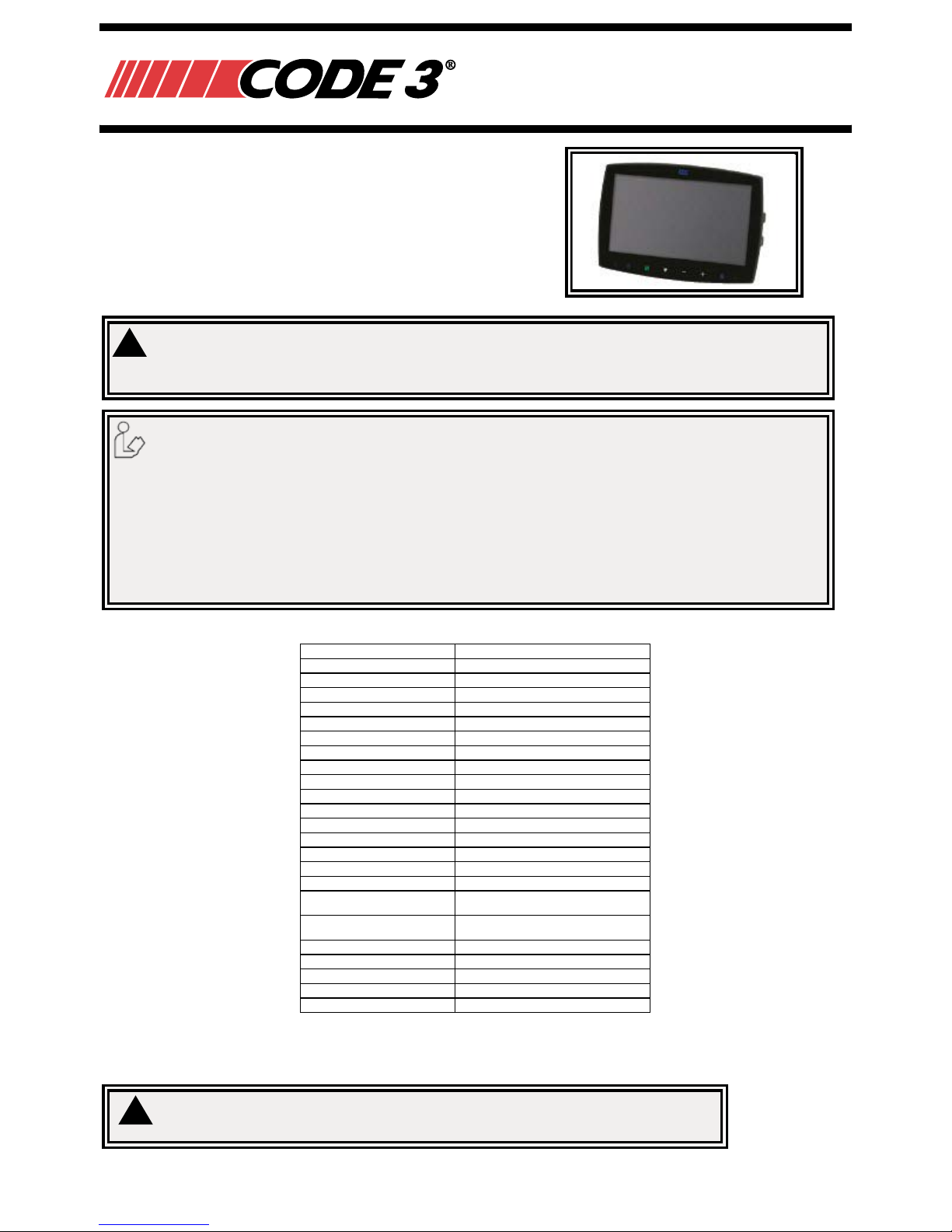
The CC7000-QM Monitor from Code 3 is designed to provide a driver
with video and audio from up to four cameras individually or together
on a split screen for ultimate driver awareness. When properly
installed and used in conjunction with vehicle mirrors, Code 3’s
CC7000-QM assists drivers during hazardous parking and backing
situations. This manual provides information about installation,
function, safety, maintenance, replacement parts and warranty.
Failure to install or use this product according to manufacturers recommendations may result in property damage, serious injury, and/or death to
those you are seeking to protect!
!
WARNING!
1. Proper installation combined with operator training in the use, care, and maintenance of emergency warning devices are essential to ensure
the safety of you and those you are seeking to protect.
2. Exercise caution when working with live electrical connections.
3. This product must be properly grounded. Inadequate grounding and/or shorting of electrical connections can cause high current arcing,
which can cause personal injury and/or severe vehicle damage, including re.
4. Proper placement and installation are vital to the performance of this warning device. Install this product so that output performance of the
system is maximized and the controls are placed within convenient reach of the operator so that s/he can operate the system without losing
eye contact with the roadway.
5. It is the responsibility of the vehicle operator to ensure during use that all features of this product work correctly. In use, the vehicle operator
should ensure the projection of the warning signal is not blocked by vehicle components (i.e., open trunks or compartment doors), people,
vehicles or other obstructions.
Do not install and/or operate this safety product unless you have read and understand the safety information
contained
Specications:
Monitors EC7003-QM 7” LCD Monitor
Image 7” LCD Color, 16:9
Controller 4 Camera
Voltage 12-24VDC
Power Consumption 25 W Max
Mirror Imaging Yes (via Camera and Monitor Switch)
Split Screen Feature Yes
AV Compatible Yes
DVR Compatible No
Audio Yes
Contrast/Brightness Yes
Light Sensor Day/Night Auto Dim
Camera Selection 1-4 Via Trigger Wires
Connection: CAM Female 4 Pin Threaded
Connection (Monitor Pigtail) Male 22 Pin
Connection: CB N/A
Housing Plastic
Mounting
Permanent - HD (2 bracket options
provided)
Mech. Vibration
Pedestal Bracket - 3G
Cradle Bracket - 8G
Weight 1.26 lbs
Dimensions (WxHxD) 7.21”x5.04”x1.24”
Operating Temp 4°F to 158°F
Remote Control Ye s
Approvals FCC, CE, RoHS
Installation, Wiring and Function
Caution! When drilling into any vehicle surface, make sure that the area is free from any electrical wires, fuel lines,
vehicle upholstery, etc. that could be damaged.
!
Installation Instructions
CC7000-QM Monitor
Page 2

920-0497-00 Rev. A Page 2 of 8
Notes:
1. Larger wires and tight connections will provide longer service life for components. For high current wires it is recommended
that terminal blocks or soldered connections be used with shrink tubing to protect the connections. Do not use insulation
displacement connectors (e.g., 3M Scotchlock type connectors)
2. Route wiring using grommets and sealant when passing through compartment walls. Minimize the number of splices to
reduce voltage drop. High ambient temperatures (e.g., under-hood) will signicantly reduce the current carrying capacity of
wires, fuses, and circuit breakers. All wiring should conform to the minimum wire size and other recommendations of the
manufacturer and be protected from moving parts and hot surfaces. Looms, grommets, cable ties, and similar installation
hardware should be used to anchor and protect all wiring.
3. Fuses or circuit breakers should be located as close to the power takeoff points as possible and properly sized to protect the
wiring and devices.
4. Particular attention should be paid to the location and method of making electrical connections and splices to protect these
points from corrosion and loss of conductivity.
5. Ground termination should be only be made to substantial chassis components, preferably directly to the vehicle battery.
6. Circuit breakers are very sensitive to high temperatures and will “false trip” when mounted in hot enviroments or operated
close to their capacity.
Wiring:
CCTC20-4
Important! Waterproof all connections whether inside or outside the vehicle by using sealant and wrapping
with insulation tape. Wrap tape tightly, overlapping by one-half widths so there are no gaps.
A - Right Camera (Blue)
B - Left Camera (White)
C - Back Camera (Brown)
D - Front Camera (Green)
1 - AUX Audio Input
2 - Rec. Video Output (Green)
3 - Live Video Output (Yellow)
4 - Audio Output (White)
5 - Left Trigger (White)
6 - Right Trigger (Blue)
7 - Front Trigger (Green)
8 - Back Trigger (Brown)
9 - Split Trigger (Yellow)
10 - Ground (Black)
11 - Power (Red)
RCA:
12 - DVD Video Output (Yellow)
13 - DVD Audio Output (White)
14 - Black
22 Pin Male 22 Pin Female
4 Pin
Female
3A FUSE
A B C D 1 2 3 4 5 6 7 8 9 10 11 12 13 14
WIRING DEFINED
Page 3
Page 3 of 8920-0497-00 Rev. A
Monitor:
Model CC7000-QM
WARNING!
To prevent accidental shock, DO NOT OPEN THE MONITOR CASE. Opening the monitor case will expose the inside of the monitor to conditions
that could adversely affect performance. Any evidence of tampering with sealed components will void the warranty.
Important! Do not expose the monitor to water, it is not waterproof. Any water that leaks into the monitor could cause extensive damage.
!
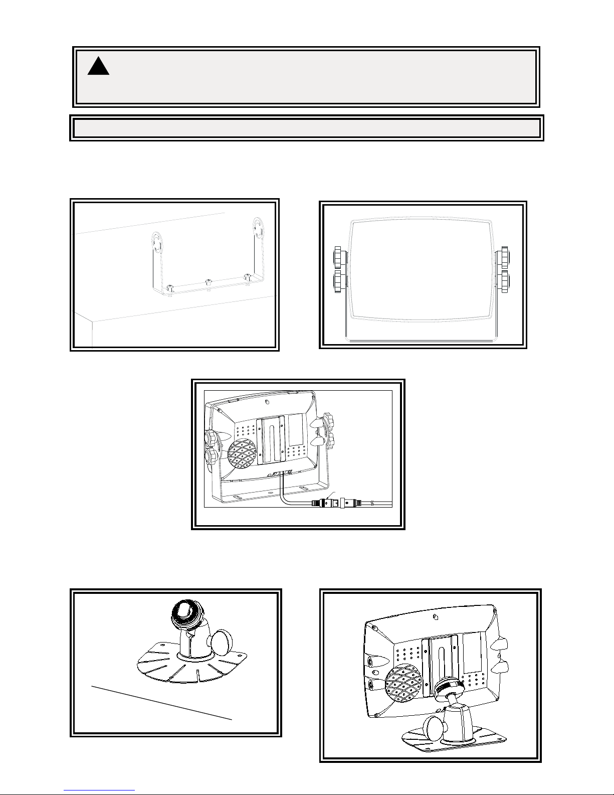
Installation: CC7000-QM
Installation instruction of using U-support bracket
1. Select suitable position on vehicle and x the U-support bracket with screws (Figure 3)
2. Fix the monitor to the U-support bracket with angle adjustment screws and adjust the view angle of the monitor (Figure 4)
3. Put on the sun-visor and connect the monitor with the AV and power supply conversion cable (Figure 5)
Figure 4Figure 3
Figure 5
22 P
Figure 6
Figure 7
Stick the base
support onto the
vehicle
Installation instruction of using pedestal base
1. Select suitable position on vehicle and x the base support. (Figure 6)
2. Fix the monitor to the base support and adjust the view angle. (Figure 7)
3. Put on the sun-visor and connect the monitor with the AV and power supply conversion cable (Figure 8)
Page 4

920-0497-00 Rev. A Page 4 of 8
22 PIN MALE
Figure 8
Remote Control OperaƟŽŶ
1. MUTE
To mute/unmute the volume
2. POWER
Power off/on button
3. MENU
Menu control button
4. UP
Menu selection up
5. DN
Menu selection and display mode (single, dual, triple, quad-view, PIP image) selection
6. VOL-
to decrease the volume and switch between values of each sub-menu
7. VOL+
To increase volume and switch between values of each sub-menu
8. MODE
Menu selection and display mode (single, dual, triple, quad-view, PIP image) selection
9. SEL.
Jump key selector. Fast jump to the display mode specified by SYSTEM SETUP
10. P/N
PAL/NTSC TV system selector
11. LANG
Language selection
12. REST
To restore factory settings
13. AV
To go to/leave DVD channel
1. MUTE
To mute/unmute the volume
2. POWER
Power off/on button
3. MENU
Menu control button
4. UP
Menu selection up
5. DN
Menu selection and display mode (single, dual, triple, quad-view, PIP image) selection
6. VOL to decrease the volume and switch between values of each sub-menu
7. VOL+
To increase volume and switch between values of each sub-menu
8. MODE
Menu selection and display mode (single, dual, triple, quad-view, PIP image) selection
9. SEL.
Jump key selector. Fast jump to the display mode specified by SYSTEM SETUP
10. P/N
PAL/NTSC TV system selector
11. LANG
Language selection
12. REST
To restore factory settings
13. AV
To go to/leave DVD channel
WARNING!
1. Please align the remote control with the remote signal receiver window to operate.
2. Never disassemble the remote control or allow it to drop or get wet.
!
Monitor Parts Idenficaon
EC7003-M
Color LCD
Screen
Remote Signal IR Receiver
Power
Menu
Menu Selecon and Display Mode
Volume Down
Volume Up
Jump Key
Speaker
Installaon port for
center mount bracket
LDR
CC7000-QM
Page 5

Page 5 of 8920-0497-00 Rev. A
Menu Operaon
Press the Menu buon on the remote control or the Menu buon on the monitor screen.
Use the Up & Down arrow on the remote control or the down arrow on the monitor screen to toggle
between menus.
Use Volume Up on the remote control or the + buon on the monitor screen to select highlighted menu or Volume
Down on the remote control or the – buon on the monitor screen to go back to the previous menu.
or
CAMERA: To select the camera that needs adjustment.
BRIGHTNESS: To adjust the camera’s brightness.
CONTRAST: To adjust the camera’s contrast.
COLOR: To adjust the camera’s color.
TINT: To adjust camera’s nt.
MIRROR: To turn mirror feature on or off.
or
MAIN MENU
CAMERA
SETUP
CAMERA
NAME
OSD
SETUP
SYSTEM
SETUP
TRIGGER
SETUP
TRIGGER
PRIORITY
SPLIT
SETUP
RESET
ALL
CAMERA SETUP
CAMERA
(LEFT/RIGHT/FRONT/BACK)
BRIGHTNESS
(select brightness)
CONTRAST
(select contrast)
COLOR
(select color)
TINT
(select nt)
MIRROR
(ON/OFF)
MAIN MENU
CAMERA
SETUP
CAMERA
NAME
OSD
SETUP
SYSTEM
SETUP
TRIGGER
SETUP
TRIGGER
PRIORITY
SPLIT
SETUP
RESET
ALL
CAMERA NAME
LEFT
_ _ _ _ _ _ _ _
RIGHT
_ _ _ _ _ _ _ _
FRONT
_ _ _ _ _ _ _ _
BACK
_ _ _ _ _ _ _ _
DISPLAY
(ON/OFF)
LEFT/RIGHT/FRONT/BACK: To rename the camera locaons.
DISPLAY: To turn on/off display.
LEFT/RIGHT/FRONT/BACK: To rename the camera locaons.
DISPLAY: To turn on/off display.
or
SCALE: Turn on/off electric distance label. When set as ON, electronic distance label will be displaced when rear
view camera (camera 3) is acvated.
INPUT SCAN: To turn on/off auto idenficaon of camera inputs. When INPUT SCAN is set as ON, monitor will
display connected cameras and skip inputs not in connecon.
SPEAKER: To turn speaker on/off.
TURN SHOW: To turn Turn Show on/off.
BOUNDARY: To set color of the separaon line between camera inputs. White, gray, black and uncolored are
available.
LANGUAGE: To set OSD language. English, Finish, Netherlands, Espańol, Deutsch and Italiano.
SOFTWARE VERSION: To be updated at all mes.
MAIN MENU
CAMERA
SETUP
CAMERA
NAME
OSD
SETUP
SYSTEM
SETUP
TRIGGER
SETUP
TRIGGER
PRIORITY
SPLIT
SETUP
RESET
ALL
OSD SETUP
SCALE
(ON/OFF)
INPUT
(ON/OFF)
SPEAKER
(ON/OFF)
TURN SHOW
(ON/OFF)
BOUNDARY
BLACK/GRAY/WHITE/OFF
LANGUAGE
(see selecon below)
(SOFTWARE VERSION)
Page 6

920-0497-00 Rev. A Page 6 of 8
LEFT/RIGHT/FRONT/BACK: To rename the camera locaons.
DISPLAY: To turn on/off display.
or
SCALE: Turn on/off electric distance label. When set as ON, electronic distance label will be displaced when rear
view camera (camera 3) is acvated.
INPUT SCAN: To turn on/off auto idenficaon of camera inputs. When INPUT SCAN is set as ON, monitor will
display connected cameras and skip inputs not in connecon.
SPEAKER: To turn speaker on/off.
TURN SHOW: To turn Turn Show on/off.
BOUNDARY: To set color of the separaon line between camera inputs. White, gray, black and uncolored are
available.
LANGUAGE: To set OSD language. English, Finish, Netherlands, Espańol, Deutsch and Italiano.
SOFTWARE VERSION: To be updated at all mes.
or
REC-V OUT: To set the camera input(s) to be recorded when connected to DVR via the green RCA wire. Le-
side, right-side, front view, rear view camera and quad view image can be selected.
AUTOSCAN: To set the auto scanning funcon. When AUTOSCAN is set as ON, monitor will automacally switch
between connected camera inputs and quad image.
SCAN DELAY: To set the switching me of AUTOSCAN. Switching me frame: 0-60 seconds.
JUMP KEY: To set the shortcut display mode from the 13 modes to the le. It can be acvated by jump key
selector. Opons: Le, Right, Front, Back, Quad, Dual, Dual2, Triple, Triple 2, Pip 1, Pip 2, Pip 3, H-Split, Trefoil
and Y-Split.
P-ON MODE: To set the default display model from the 13 modes to the le or STANDBY mode. Opons: Le,
Right, Front, Back, Quad, Dual, Dual2, Triple, Triple 2, Pip 1, Pip 2, Pip 3, H-Split, Trefoil and Y-Split.
MAIN MENU
CAMERA
SETUP
CAMERA
NAME
OSD
SETUP
SYSTEM
SETUP
TRIGGER
SETUP
TRIGGER
PRIORITY
SPLIT
SETUP
RESET
ALL
OSD SETUP
SCALE
(ON/OFF)
INPUT
(ON/OFF)
SPEAKER
(ON/OFF)
TURN SHOW
(ON/OFF)
BOUNDARY
BLACK/GRAY/WHITE/OFF
LANGUAGE
(see selecon below)
(SOFTWARE VERSION)
MAIN MENU
CAMERA
SETUP
CAMERA
NAME
OSD
SETUP
SYSTEM
SETUP
TRIGGER
SETUP
TRIGGER
PRIORITY
SPLIT
SETUP
RESET
ALL
SYSTEM SETUP
REC-V OUT
(see selecon below)
AUTO-SCAN
(ON/OFF)
SCAN DELAY
(select scan delay)
JUMP KEY
(see selecon below)
P-ON
(see selecon below)
BEEP
(ON/OFF)
SYSTEM
(PAL/NTSC)
DIMMER
(selecon backlight)
BEEP: To turn on/off the warning tone. Default seng is ON and there will be a beeping sound when menu is
being operated.
SYSTEM: To set TV system: PAL/NTSC.
DIMMER: To set backlighng brightness level of screen. Five levels and AUTO opon are available; the higher
the level, the brighter. When set as AUTO, backlighng automacally adjusts in accordance with the outer
brightness.
or
TURN IMAGE: To set the camera input(s) to be displayed when le-side camera (camera 1)/right side camera
(camera 2) is acvated. When set as SINGLE, correspond camera input will be displayed when either camera is
acvated. When set as SPLIT, split image of le-side and rear view camera will be displayed when le-side
camera is acvated; split image of right side and rear view camera will be displayed when right side camera is
acvated.
REAR IMAGE: To set the camera input(s) to be displayed when rear view camera is acvated. When set as
BACK, the rear view camera will be displayed when acvated. When set as TRIPLE, le-side, right-side and rear
view camera will be displayed.
TIRGGER DELAY: To set the delaying me of video display when trigger signals goes off. Delaying me frame: 0-
30 seconds.
SPLIT SCREEN: To set camera input(s) to be displayed when ‘split’ trigger wire is acvated. LEFT/RIGHT is to set
the camera input to be displayed on the le/right side of monitor screen. AUDIO is to set the audio output form
any of the four cameras.
MAIN MENU
CAMERA
SETUP
CAMERA
NAME
OSD
SETUP
SYSTEM
SETUP
TRIGGER
SETUP
TRIGGER
PRIORITY
SPLIT
SETUP
RESET
ALL
TRIGGER SETUP
TURN IMAGE
(SINGLE/SPLIT)
REAR IMAGE
(BACK/TRIPLE)
TRIGGER DELAY
(select delay)
SPLIT SCREEN:
LEFT
(LEFT/FRONT/BACK)
RIGHT
(RIGHT/FRONT/BACK)
AUDIO
(all four cameras)
Page 7

Page 7 of 8920-0497-00 Rev. A
BEEP: To turn on/off the warning tone. Default seng is ON and there will be a beeping sound when menu is
being operated.
SYSTEM: To set TV system: PAL/NTSC.
DIMMER: To set backlighng brightness level of screen. Five levels and AUTO opon are available; the higher
the level, the brighter. When set as AUTO, backlighng automacally adjusts in accordance with the outer
brightness.
or
TURN IMAGE: To set the camera input(s) to be displayed when le-side camera (camera 1)/right side camera
(camera 2) is acvated. When set as SINGLE, correspond camera input will be displayed when either camera is
acvated. When set as SPLIT, split image of le-side and rear view camera will be displayed when le-side
camera is acvated; split image of right side and rear view camera will be displayed when right side camera is
acvated.
REAR IMAGE: To set the camera input(s) to be displayed when rear view camera is acvated. When set as
BACK, the rear view camera will be displayed when acvated. When set as TRIPLE, le-side, right-side and rear
view camera will be displayed.
TIRGGER DELAY: To set the delaying me of video display when trigger signals goes off. Delaying me frame: 0-
30 seconds.
SPLIT SCREEN: To set camera input(s) to be displayed when ‘split’ trigger wire is acvated. LEFT/RIGHT is to set
the camera input to be displayed on the le/right side of monitor screen. AUDIO is to set the audio output form
any of the four cameras.
or
TRIGGER PRIORITY: To set camera trigger priority.
MAIN MENU
CAMERA
SETUP
CAMERA
NAME
OSD
SETUP
SYSTEM
SETUP
TRIGGER
SETUP
TRIGGER
PRIORITY
SPLIT
SETUP
RESET
ALL
TRIGGER SETUP
TURN IMAGE
(SINGLE/SPLIT)
REAR IMAGE
(BACK/TRIPLE)
TRIGGER DELAY
(select delay)
SPLIT SCREEN:
LEFT
(LEFT/FRONT/BACK)
RIGHT
(RIGHT/FRONT/BACK)
AUDIO
(all four cameras)
MAIN MENU
CAMERA
SETUP
CAMERA
NAME
OSD
SETUP
SYSTEM
SETUP
TRIGGER
SETUP
TRIGGER
PRIORITY
SPLIT
SETUP
RESET
ALL
TRIGGER PRIORITY
1ST PRIORITY
(FRONT/BACK/SPLIT/LEFT/RIGHT)
2ND PRORITY
(FRONT/BACK/SPLIT/LEFT/RIGHT)
3RD PRIORITY
(FRONT/BACK/SPLIT/LEFT/RIGHT)
4TH PRIORITY
(FRONT/BACK/SPLIT/LEFT/RIGHT)
5TH PRIORITY
(FRONT/BACK/SPLIT/LEFT/RIGHT)
or
SPLIT SETUP: To set up split screen view.
Click on Volume Up to reset to factory sengs.
SPLIT SETUP
SPLIT
SCREEN
SPLIT
SCREEN
TRIPLE
SCREEN
TRIPLE
SCREEN
QUAD
SCREEN
PIP
SCREEN
PIP
SCREEN
PIP
SCREEN
TGREFOIL
SCREEN
Y-SPLIT
SCREEN
MAIN MENU
CAMERA
SETUP
CAMERA
NAME
OSD
SETUP
SYSTEM
SETUP
TRIGGER
SETUP
TRIGGER
PRIORITY
SPLIT
SETUP
RESET
ALL
SPLIT SETUP
SPLIT
SCREEN
SPLIT
SCREEN
TRIPLE
SCREEN
TRIPLE
SCREEN
QUAD
SCREEN
PIP
SCREEN
PIP
SCREEN
PIP
SCREEN
TGREFOIL
SCREEN
Y-SPLIT
SCREEN
LEFT
LEFT/RIGHT/FRONT/BACK
RIGHT
LEFT/RIGHT/FRONT/BACK
AUDIO
LEFT/RIGHT/FRONT/BACK
*Click the menu buon to
go one screen back
MAIN MENU
CAMERA
SETUP
CAMERA
NAME
OSD
SETUP
SYSTEM
SETUP
TRIGGER
SETUP
TRIGGER
PRIORITY
SPLIT
SETUP
RESET
ALL
Page 8

920-0497-00 Rev. A Page 8 of 8
This device complies with Part 15 of the FCC Rules. Operation is subject to the following two conditions:
(1) This device may not cause harmful interference.
(2) This device must accept any interference received, including interference that may cause
undesired operation.
Declaration of conformity:
10986 North Warson Road
St. Louis, MO 63114
Technical Service:
(314) 996-2800
c3_tech_support@code3esg.com
www.code3esg.com
A Division of ESG | www.eccogroup.com
Manufacturer Limited Warranty Policy:
Manufacturer warrants that on the date of purchase this product will conform to Manufacturer’s specications for this product (which are available from the Manufacturer upon request). This Limited Warranty extends for Sixty (60) months from the date of purchase.
DAMAGE TO PARTS OR PRODUCTS RESULTING FROM TAMPERING, ACCIDENT, ABUSE, MISUSE, NEGLIGENCE, UNAPPROVED MODIFICATIONS, FIRE OR OTHER HAZARD; IMPROPER INSTALLATION OR OPERATION; OR NOT BEING MAINTAINED IN ACCORDANCE WITH THE
MAINTENANCE PROCEDURES SET FORTH IN MANUFACTURER’S INSTALLATION AND OPERATING INSTRUCTIONS VOIDS THIS LIMITED WARRANTY.
Exclusion of Other Warranties:
MANUFACTURER MAKES NO OTHER WARRANTIES, EXPRESS OR IMPLIED. THE IMPLIED WARRANTIES FOR MERCHANTABILITY, QUALITY
OR FITNESS FOR A PARTICULAR PURPOSE, OR ARISING FROM A COURSE OF DEALING, USAGE OR TRADE PRACTICE ARE HEREBY EXCLUDED AND SHALL NOT APPLY TO THE PRODUCT AND ARE HEREBY DISCLAIMED, EXCEPT TO THE EXTENT PROHIBITED BY APPLICABLE
LAW. ORAL STATEMENTS OR REPRESENTATIONS ABOUT THE PRODUCT DO NOT CONSTITUTE WARRANTIES.
Remedies and Limitation of Liability:
MANUFACTURER’S SOLE LIABILITY AND BUYER’S EXCLUSIVE REMEDY IN CONTRACT, TORT (INCLUDING NEGLIGENCE), OR UNDER ANY
OTHER THEORY AGAINST MANUFACTURER REGARDING THE PRODUCT AND ITS USE SHALL BE, AT MANUFACTURER’S DISCRETION, THE
REPLACEMENT OR REPAIR OF THE PRODUCT, OR THE REFUND OF THE PURCHASE PRICE PAID BY BUYER FOR NON-CONFORMING PRODUCT. IN NO EVENT SHALL MANUFACTURER’S LIABILITY ARISING OUT OF THIS LIMITED WARRANTY OR ANY OTHER CLAIM RELATED TO
THE MANUFACTURER’S PRODUCTS EXCEED THE AMOUNT PAID FOR THE PRODUCT BY BUYER AT THE TIME OF THE ORIGINAL PURCHASE.
IN NO EVENT SHALL MANUFACTURER BE LIABLE FOR LOST PROFITS, THE COST OF SUBSTITUTE EQUIPMENT OR LABOR, PROPERTY
DAMAGE, OR OTHER SPECIAL, CONSEQUENTIAL, OR INCIDENTAL DAMAGES BASED UPON ANY CLAIM FOR BREACH OF CONTRACT, IMPROPER INSTALLATION, NEGLIGENCE, OR OTHER CLAIM, EVEN IF MANUFACTURER OR A MANUFACTURER’S REPRESENTATIVE HAS BEEN
ADVISED OF THE POSSIBILITY OF SUCH DAMAGES. MANUFACTURER SHALL HAVE NO FURTHER OBLIGATION OR LIABILITY WITH RESPECT
TO THE PRODUCT OR ITS SALE, OPERATION AND USE, AND MANUFACTURER NEITHER ASSUMES NOR AUTHORIZES THE ASSUMPTION OF
ANY OTHER OBLIGATION OR LIABILITY IN CONNECTION WITH SUCH PRODUCT.
This Limited Warranty denes specic legal rights. You may have other legal rights which vary from jurisdiction to jurisdiction. Some jurisdictions do not allow the exclusion or limitation of incidental or consequential damages.
Product Returns:
If a product must be returned for repair or replacement*, please contact our factory to obtain a Return Goods Authorization Number (RGA number)
before you ship the product to Code 3®, Inc. Write the RGA number clearly on the package near the mailing label. Be sure you use sufcient
packing materials to avoid damage to the product being returned while in transit.
*Code 3®, Inc. reserves the right to repair or replace at its discretion. Code 3®, Inc. assumes no responsibility or liability for expenses incurred for the removal and /or reinstallation of products requiring service and/or repair.; nor for the packaging, handling,
and shipping: nor for the handling of products returned to sender after the service has been rendered.
 Loading...