

Page 1
INSTALLATION
MANUAL
SIDE MARKER LED LIGHT HEAD INSTALLATION
DRIVER AND PASSENGER SIDE MARKER LIGHTS 2011-12 CHEVROLET CAPRICE
2011-12 CAPRICE PPV
CONTENTS:
Installation & Mounting.........................................................2
Parts List...........................................................3
Warranty................................................................................4
For future reference record your product's serial no. here __________________________________________
IMPORTANT:
Read all instructions and warnings before installing and using.
This manual must be delivered to the end user of this equipment.
INSTALLER:
Page 2
Installation Instructions
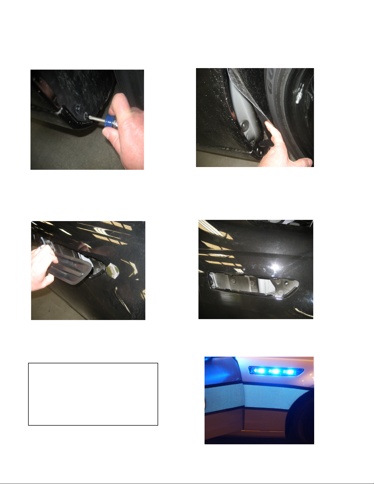
STEP 1, ACCESS FRONT FENDER
FROM WHEEL WELL BASE BY
REMOVING (2) BOTTOM PHILLIPS
HEAD SCREWS FROM WHEEL
WELL COVER
STEP 3. REMOVE THE SIDE
MARKER COVER FROM FENDER
STEP 2. PULL OUT WHEEL WELL
COVER AT BASE TO GAIN ACCESS
FOR PUSHING OUT THE BOTTOM
CLIPS ON THE SIDE MARKER
COVER IN THE FRONT FENDER.
STEP 4. INSTALL OR LOCATE
(4 wire) WIRING HARNESS FOR
LIGHTS
WIRE IDENTIFICATION TABLE:
Green wire- Syncronization
White wire- Change ash pattern
Red wire- Power
Black wire- Ground
STEP 5. INSTALL (4) PIN WATERPROOF
CONNECTOR SUPPLIED IN KIT ONTO
WIRE HARNESS IN VEHICLE
STEP 6. PLUG IN LIGHT HEAD TO HARNESS AND SNAP LIGHT HEAD ASSEMBLY INTO VEHICLE FRONT FENDER.
2
Page 3

PARTS LIST:
Part Description Qty: Part Number
Driver Side Light Assembly 1 contact factory
Passenger Side Light Assembly 1 contact factory
(Each light assembly is individually congured to the customer specications with LED color, placement and lens color selections for either
the Driver or Passenger Side products. )
WARNING!
WARNING!
Larger wires and tight connections will provide longer service life for components. For high current wires it
is highly recommended that terminal blocks or soldered connections be used with shrink tubing to protect
the connections. Do not use insulation displacement connectors (e.g. 3M® Scotchlock type connectors).
Route wiring using grommets and sealant when passing through compartment walls. Minimize the
number of splices to reduce voltage drop. High ambient temperatures (e.g. under hood) will signicantly
reduce the current carrying capacity of wires, fuses, and circuit breakers. Use "SXL" type wire in engine
compartment. All wiring should conform to the minimum wire size and other recommendations of the
manufacturer and be protected from moving parts and hot surfaces. Looms, grommets, cable ties, and
similar installation hardware should be used to anchor and protect all wiring. Fuses or circuit breakers
should be located as close to the power takeoff points as possible and properly sized to protect the wiring
and devices. Particular attention should be paid to the location and method of making electrical connections
and splices to protect these points from corrosion and loss of conductivity. Ground terminations should
only be made to substantial chassis components, preferably directly to the vehicle battery. The user should
install a fuse sized to approximately 125% of the maximum Amp capacity in the supply line to protect
against short circuits. For example, a 30 Amp fuse should carry a maximum of 24 Amps. DO NOT USE
1/4" DIAMETER GLASS FUSES AS THEY ARE NOT SUITABLE FOR CONTINUOUS DUTY IN SIZES
ABOVE 15 AMPS. Circuit breakers are very sensitive to high temperatures and will "false trip" when
mounted in hot environments or operated close to their capacity.
Utilizing non-factory supplied screws and/or mounting brackets and/or the improper
number of screws may result in loss of warranty coverage on the equipment.
3
Page 4

WARRANTY
This product was tested and found to be operational at the time of manufacture. Provided this product
is installed and operated in accordance with the manufacturer's recommendations, CODE 3, Inc. guarantees
this product for a period of 5 years from the date of purchase or delivery, whichever is later (does not apply to
lamps). Units demonstrated to be defective within the warranty period will be repaired or replaced at the factory
service center at no cost.
Use of a lamp or other electrical load of a wattage higher than installed or recommended by the factory,
or use of inappropriate or inadequate wiring or circuit protection causes this warranty to become void. Failure
or destruction of the product resulting from abuse or unusual use and/or accidents is not covered by this warranty. Use of non-CODE 3, Inc. components and assemblies may cause damage to the system and/or personal
injury, and voids all warranties.
CODE 3, Inc. shall in no way be liable for other damages including consequential, indirect or special
damages whether loss is due to negligence or breach of warranty.
CODE 3, INC. MAKES NO OTHER EXPRESS OR IMPLIED WARRANTY INCLUDING, WITHOUT LIMITATION, WARRANTIES OF FITNESS OR MERCHANTABILITY, WITH RESPECT TO THIS PRODUCT.
PRODUCT RETURNS
In order to provide you with faster service, if you are going to return a product for repair or replacement*,
please contact our factory to obtain a Return Goods Authorization Number (RGA number) before you ship the
product to Code 3. Write the RGA number clearly on the package near the mailing label. Be sure you use suf-
cient packing materials to avoid damage to the product being returned while in transit.
*Code 3, Inc. reserves the right to repair or replace product at its discretion and assumes no responsibility or liability for expenses
incurred for the removal and/or reinstallation of products requiring service and/or repair.
Problems or Questions? Call our Technical Assistance HOTLINE - (314) 966-2800
10986 N. Warson Road
St. Louis, Missouri 63114-2029—USA
Ph. (314) 426-2700 Fax (314) 426-1337
www.code3pse.com
CODE 3, Inc.
Code 3 is a registered trademark of Code 3, Inc. a subsidiary of Public Safety Equipment, Inc.
4
Revision - 0, 09/2011 - Instruction Book Part No. T56571©2011
CODE 3, Inc. Printed in USA
 Loading...