

Page 1

INSTALLATION
& OPERATION
MANUAL
FLASH SERIES
Contents:
MODEL L800 ASTRO FLASH II
MODEL LL400 STAR FLASH IV
MODEL L2000 NOVA FLASH IV
FLASH SERIES
STROBE BEACONS
Introduction..................................................................................3
Unpacking & Pre-Installation .......................................................3
Installation & Mounting ................................................................3
Mounting Using Screws from Underneath ..............................3
Mounting Using Screws Driven Down Thru Base 3
Flush Mounting without Removing Lens ................................4
Headache Rack Mounting ......................................................4
Magnetic Mounting (option) .................................................... 4
Pipe Mounting ........................................................................ 4
Wiring Instructions .................................................................. 4
Maintenance ................................................................................6
Troubleshooting........................................................................... 6
Parts List ..................................................................................... 6
Full Size Mounting Template ....................................................... 7
Warranty ...................................................................................... 8
IMPORTANT:
Read all instructions and warnings before installing and using.
INSTALLER: This manual must be delivered to the end user of this equipment.
Page 2

!
WARNING!
The use of this or any warning device does not insure that all drivers can or will observe or
react to an emergency warning signal. Never take the right-of-way for granted. It is your
responsibility to be sure you can proceed safely before entering an intersection, driving
against traffic, responding at a high rate of speed, or walking on or around traffic lanes.
The effectiveness of this warning device is highly dependent upon correct mounting and
wiring. Read and follow the manufacturer’s instructions before installing or using this
device. The vehicle operator should insure daily that all features of the device operate
correctly. In use, the vehicle operator should insure the projection of the warning signal is
not blocked by vehicle components (i.e.: open trunks or compartment doors), people,
vehicles, or other obstructions.
This equipment is intended for use by authorized personnel only. It is the user’s responsibility to understand and obey all laws regarding emergency warning devices. The user
should check all applicable city, state and federal laws and regulations.
Public Safety Equipment, Inc., assumes no liability for any loss resulting from the use of this
warning device.
Proper installation is vital to the performance of this warning device and the safe operation
of the emergency vehicle. It is important to recognize that the operator of the emergency
vehicle is under psychological and physiological stress caused by the emergency situation.
The warning device should be installed in such a manner as to: A) Not reduce the output
performance of the system, B) Place the controls within convenient reach of the operator
so that he can operate the system without losing eye contact with the roadway.
Emergency warning devices often require high electrical voltages and/or currents. Properly
protect and use caution around live electrical connections. Grounding or shorting of
electrical connections can cause high current arcing, which can cause personal injury and/
or severe vehicle damage, including fire. Incandescent lamps are extremely hot, allow to
cool completely before attempting to remove.
Any electronic device may create or be affected by electromagnetic interference. After
installation of any electronic device operate all equipment simultaneously to insure that
operation is free of interference. Never power emergency warning equipment from the
same circuit or share the same grounding circuit with radio communication equipment.
PROPER INSTALLATION COMBINED WITH OPERATOR TRAINING IN THE PROPER
USE OF EMERGENCY WARNING DEVICES IS ESSENTIAL TO INSURE THE SAFETY
OF EMERGENCY PERSONNEL AND THE PUBLIC.
!
WARNING!
All devices should be mounted in accordance with the manufacturer's instructions and
securely fastened to vehicle elements of sufficient strength to withstand the forces applied
to the device. Driver and/or passenger air bags (SRS) will affect the way equipment should
be mounted. This device should be mounted by permanent installation and within the
zones specified by the vehicle manufacturer, if any. Any device mounted in the deployment
area of an air bag will damage or reduce the effectiveness of the air bag and may damage
or dislodge the device. Installer must be sure that this device, its mounting hardware and
electrical supply wiring does not interfere with the air bag or the SRS wiring or sensors.
Front or rear grille/bumper placement must avoid interference with SRS sensors. Mounting
the unit inside the vehicle by a method other than the permanent installation is not recommended as unit may become dislodged during swerving, sudden braking, or collision.
Failure to follow instructions can result in personal injury.
2
Page 3
Introduction
The Astro/Star/Nova "Flash" Series Strobe Beacons
represent the latest advances in state-of-the-art 360
degree strobe warning technology based on years of
research and testing. The latest MOSFET technology
and advanced design provide more efficient operation,
meaning superior performance, reliability and longer
life.
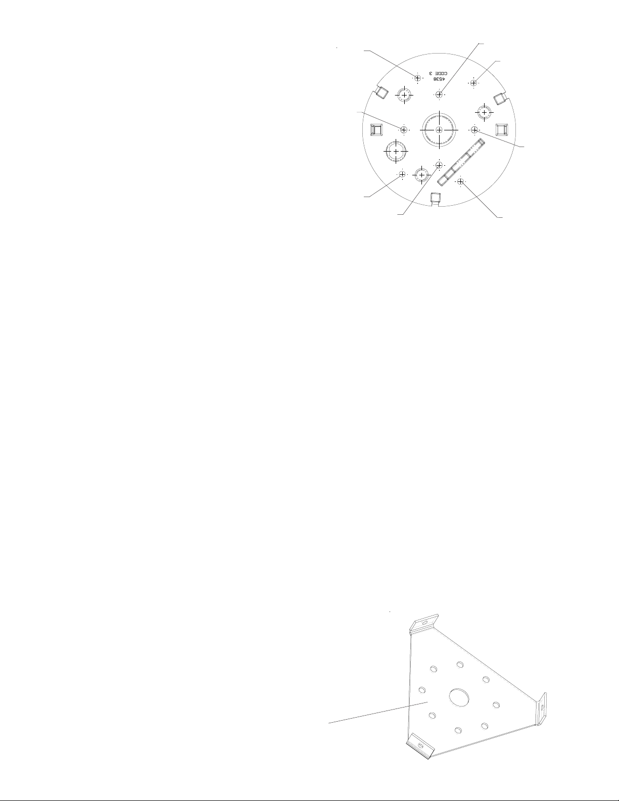
Unpacking & Pre-
Hole B
Hole A
Hole B
Hole A
Hole A
installation
Remove the beacon from the box and examine the
unit for transit damage. A battery (+12/24 VDC) or
battery charger may be used to test the beacon. To
test, connect the black wire to the negative (earth)
terminal of the battery or battery charger. Touch the red wire to the positive (+12/24 VDC) terminal and verify
the unit's operation. Reversing the power connections will activate the reverse polarity protection, resulting in
no light output.
Hole B
Hole A
FIGURE 1
Hole B
Installation & Mounting
The Flash Series Strobe Beacons are shipped fully tested and ready for installation. Refer to Figure 1 for
attachment points. Connect wiring as shown in Figure 2. Grommets and sealant should be used to keep
water out of your vehicle. The beacon will have a label covering the mounting holes "A" & "B" in the base.
The bottom label is intended to stop water entry into the beacon. Do not remove this label. Mounting screws
can be driven through this label for attachment to the vehicle.
Mounting Using Screws from
Underneath Beacon
Drill four clearance holes in mounting surface, using full size mounting hole template. (Hole A) Place the
base gasket between mounting surface and beacon. Drive 5/16-18 x 3/4 self-tapping screws up
through mounting surface into the base until tight.
Mounting Using Screws Driven Down
Through Base Into Mounting Surface
Remove lens and aluminum circuit case. Place the base gasket between mounting surface and beacon.
Drive user supplied self-drilling screws through holes into mounting surface. Alternatively, using full
size mounting hole template, drill four 11/64" holes (Hole B) and drive #8 tapping screws provided
through base and into mounting
surface. Use CAUTION not to
damage the printed circuit board
or strobe tube.
S96253
3
Page 4
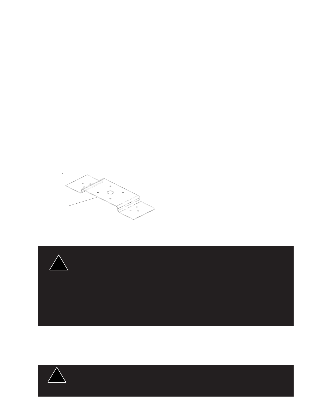
Flush Mounting Without Removing Lens
The Flash Series Flush Mount Bracket LFLMNT is available to mount the beacon to a surface without
removing the lens and without access to drive screws from underneath the beacon. Transfer the
mounting holes from the bracket to the mounting surface. Drill four 11/64" holes into the mounting
surface. Place base gasket on the mounting surface. Drive four #8 flat head screws through
mounting bracket. Place the other base gasket on top of the bracket. Remove the three screws
holding the circuit case onto beacon. Align the holes in the circuit case with the holes in the bracket
and re-attach the screws through the bracket and into the base.
Wiring Instructions
The Series 90 Strobe Beacons are shipped fully tested and ready for installation. Connect wiring as
shown in Figure 2. Use a 10 Amp fuse for circuit protection and #18 gauge or larger wire. Grommets
and sealant should be used to keep water out of your vehicle.
Flash Pattern & Dimmer Mode (Nova/Astro only)
To Select a flash pattern on the unit follow the directions provided below:
1. Turn power off and wait 10 minutes before opening the unit.
2. Remove lens and select the appropriate flash configuration. Use Figure 3 as a guide
3. Reassemble the lens.
Headache Rack Mounting
The Headache Rack Mounting Bracket(HRMNTH) is
available to mount the Flash Series beacon to a
headache rack of a flat bed truck. Mount the beacon
to the bracket using the "Mounting Using Screws from
S96246
Underneath Beacon" instructions. Mount the bracket
to the headache rack using self-drilling screws or
driving screws through pre-drilled holes
Magnetic Mounting (option)
Use optional magnetic mount for temporary mounting of the unit to stationary vehicles.
1) Rust Stains: Magnetic mounting is not intended as permanent mounting for beacons.
Long duration usage of any magnet will expose the high iron content of the steel, thereby
!
WARNING!
causing rust. The device should by removed when not used to prevent rust stains. Metallic
debris collected by the magnet will also contribute to rust stains. Insure that the magnet is
kept clean.
2) Surface rust stains can usually be removed with chrome polish, available at most auto
part stores.
3) As with any magnetically-mounted warning device, its use on the exterior of a moving
vehicle is at the sole discretion and responsibility of the user.
Magnetic mount products provide a secure, temporary installation in most circumstances
and is recommended for stationary use only. For maximum warning signal, mount the
beacon on the highest possible flat, level surface of the vehicle.
Pipe Mounting
The Strobe base will accept a standard 1" NPT pipe. Hand tighten the beacon base on the pipe thread
until the pipe bottoms out inside the unit. DO NOT OVER-TIGHTEN. Excessive torque may crack the
beacon base. Secure with a locknut to prevent unit from coming loose. Use the appropriate reducer to
mount to 3/4" or 1/2" pipe.
Using non-factory specified screws and/or mounting brackets and/or the improper number
!
WARNING!
of screws may result in failure of mounting system and severe damage to vehicle as well as
loss of warranty coverage on the equipment.
4
Page 5

Red
Wire
10 A
Fuse
Strobe
Beacon
FIGURE 3
FIGURE 2
Black
Wire
12/
24
VDC
!
WARNING!
Larger wires and tight connections will provide longer service life for components. For high
current wires it is highly recommended that terminal blocks or soldered connections be used
with shrink tubing to protect the connections. Do not use insulation displacement
connectors (e.g. 3M® Scotchlock type connectors). Route wiring using grommets and
sealant when passing through compartment walls. Minimize the number of splices to
reduce voltage drop. High ambient temperatures (e.g. under hood) will significantly reduce
the current carrying capacity of wires, fuses, and circuit breakers. Use "SXL" type wire in
engine compartment. All wiring should conform to the minimum wire size and other
recommendations of the manufacturer and be protected from moving parts and hot
surfaces. Looms, grommets, cable ties, and similar installation hardware should be used to
anchor and protect all wiring.
Fuses or circuit breakers should be located as close to the power takeoff points as possible
and properly sized to protect the wiring and devices. Particular attention should be paid to
the location and method of making electrical connections and splices to protect these points
from corrosion and loss of conductivity. Ground terminations should only be made to
substantial chassis components, preferably directly to the vehicle battery.
The user should install a fuse sized to approximately 125% of the maximum Amp capacity in
the supply line to protect against short circuits. For example, a 30 Amp fuse should carry a
maximum of 24 Amps. DO NOT USE 1/4" DIAMETER GLASS FUSES AS THEY ARE NOT
SUITABLE FOR CONTINUOUS DUTY IN SIZES ABOVE 15 AMPS. Circuit breakers are
very sensitive to high temperatures and will "false trip" when mounted in hot
environments or operated close to their capacity.
5
Page 6

Maintenance
The Flash Series strobes have a field replaceable Xenon flashtube. (See parts list for part numbers) The
flashtube snap mounts onto the printed circuit board. Care should be taken to ensure that the tube holder
guide pins are inserted into the printed circuit board and that the base of
the tube holder is flush with the printed circuit board. Do not remove the circuit board from the base. Service
the unit in dry locations. CAUTION: Unit contains high voltages and high temperatures, disconnect from
power and wait 10 minutes before servicing.
Strobe lamps are extremely hot! Allow to cool completely before attempting to remove.
Gloves and eye protection should be worn when handling strobe flashtubes as they are
!
WARNING!
pressurized and accidental breakage can result in flying glass. High voltages and/or
temperatures are present inside of strobe units. Disconnect from power and wait 10
minutes prior to servicing.
Troubleshooting
PROBLEM PROBABLE CAUSE REMEDY
No Output
External Fuse Blows
Improper Flash Pattern
a.) Unit power leads hooked up backwards.
b.) Output capacitor shorted.
c.) Flashtube worn.
d.) Flashtube polarity backwards
a.) Fuse not proper ampere rating.
b.) Wiring to unit shorted.
c.) Power supply failure.
a.) Flashtube worn.
b.) Output capacitor worn.
c.) Jumpers in wrong position (variable
flash only).
a.) Reverse power leads.
b.) Return for service.
c.) Replace flashtube.
d.) Reverse flash tube.
a.) Replace with proper sized fuse.
b.) Replace wiring to unit.
c.) Return for service.
a.) Replace flashtube.
b.) Return unit for service.
c.) Reset jumpers (variable
flash only).
6
Page 7

REPLACEMENT PARTS LIST
PART NO. DESCRIPTION
T05606 XENON FLASH TUBE
T04537 ALUMINUM CIRCUIT CASE
T04538 DIE CAST BASE
T02239 LENS DUST COVER
T13959 BRANCH GUARD FOR 4" LENS
T13601 BRANCH GUARD FOR 6" LENS
T02234 6" AMBER LENS
T02233 6" BLUE LENS
T02231 6" CLEAR LENS
T02230 6” GREEN LENS
T02232 6” RED LENS
T02244 4” AMBER LENS
T02243 4” BLUE LENS
T02241 4” CLEAR LENS
T02240 4” GREEN LENS
T02242 4” RED LENS
T13072 BASE GASKET
Full Size Mounting Template
7
Page 8

WARRANTY
This product was tested and found to be operational at the time of manufacture. Provided this
product is installed and operated in accordance with the manufacturer's recommendations, Public Safety
Equipment, Inc. guarantees all parts and components except the lamps for a period of 2 year from the
date of purchase or delivery, whichever is later. Units demonstrated to be defective within the warranty
period will be repaired or replaced at the factory service center at no cost.
Use of a lamp or other electrical load of a wattage higher than installed or recommended by the
factory, or use of inappropriate or inadequate wiring or circuit protection causes this warranty to become
void. Failure or destruction of the product resulting from abuse or unusual use and/or accidents is not
covered by this warranty.
Public Safety Equipment, Inc. shall in no way be liable for other damages including consequential,
indirect or special damages whether loss is due to negligence or breach of warranty.
Public Safety Equipment, INC. MAKES NO OTHER EXPRESS OR IMPLIED WARRANTY
INCLUDING, WITHOUT LIMITATION, WARRANTIES OF FITNESS OR MERCHANTABILITY, WITH
RESPECT TO THIS PRODUCT.
PRODUCT RETURNS
In order to provide you with faster service, if you are going to return a product for repair or replacement*, please contact our factory to obtain a Return Goods Authorization Number (RGA number)
before you ship the product to Public Safety Equipment, Inc.. Write the RGA number clearly on the
package near the mailing label. Be sure you use sufficient packing materials to avoid damage to the
product being returned while in transit.
*Public Safety Equipment, Inc. reserves the right to repair or replace product at its discretion and assumes no responsibility or liability for expenses incurred for the removal and/or reinstallation of products requiring service and/or repair.
NEED HELP? Call our Technical Assistance Hotline - (314) 996-2800
Public Safety Equipment, Inc.
St. Louis, Missouri 63114-2029—USA
PSE Amber is a registered trademark of Public Safety Equipment, Inc.
3M is a registered trademark of 3M Company
Revision 2, 03/2006 - Instruction Book Part No. T04542
©2002-6 Public Safety Equipment, Inc. Printed in USA
10986 N. Warson Road
www.code3pse.com
 Loading...