

Page 1
INSTALLATION &
OPERATION
MANUAL
IMPORTANT:
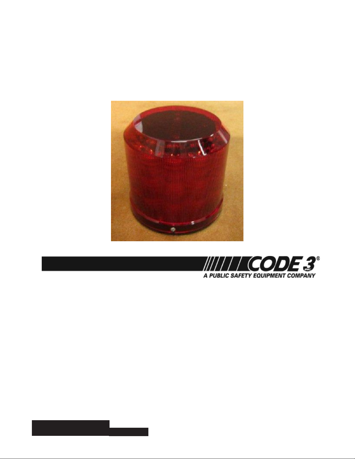
ARCH™ Beacon
Contents:
Introduction................................................................................2
Features and Specications.....................................................2
Flash Patterns.........................................................................3-4
Dimensions.......................................................................5
Installation & Mounting.......................................................5-7
Wiring..............................................................................8
Operation.........................................................................8
Maintenance&Troubleshooting............................................9
Notes ...............................................................................10-11
Warranty........................................................................12
Read all instructions and warnings before installing and using.
INSTALLER: This manual must be delivered to the end user of this equipment.
1
Page 2

Introduction
The ARCH™ Beacon is a weatherproof LED based warning light that contains 36 state-of-the-art high intensity
LEDs in three stacked rows. The unique design efciently captures light from the LEDs with individual optics
that diffuse the light in an effective warning pattern.
This Product contains high intensity LED devices. To prevent eye damage, DO NOT stare
WARNING!
WARNING!
The use of this or any warning device does not insure that all drivers can or will observe or react to an emergency
warning signal. Never take the right-of-way for granted. It is your responsibility to be sure you can proceed
safely before entering an intersection, driving against trafc, responding at a high rate of speed, or walking on
or around trafc lanes.
The effectiveness of this warning device is highly dependent upon correct mounting and wiring. Read and follow
the manufacturer’s instructions before installing or using this device. The vehicle operator should insure daily that
all features of the device operate correctly. In use, the vehicle operator should insure the projection of the warning
signal is not blocked by vehicle components (i.e.: open trunks or compartment doors), people, vehicles, or other
obstructions. This equipment is intended for use by authorized personnel only. It is the user’s responsibility to
understand and obey all laws regarding emergency warning devices. The user should check all applicable city,
state and federal laws and regulations.
Code 3 , Inc., assumes no liability for any loss resulting from the use of this warning device.
Proper installation is vital to the performance of this warning device and the safe operation of the emergency
vehicle. It is important to recognize that the operator of the emergency vehicle is under psychological and physiological stress caused by the emergency situation. The warning device should be installed in such a manner as
to: A) Not reduce the output performance of the system, B) Place the controls within convenient reach of the
operator so that he can operate the system without losing eye contact with the roadway.
Emergency warning devices often require high electrical voltages and/or currents. Properly protect and use caution around live electrical connections. Grounding or shorting of electrical connections can cause high current
arcing, which can cause personal injury and/or severe vehicle damage, including re.
PROPER INSTALLATION COMBINED WITH OPERATOR TRAINING IN THE PROPER USE OF EMERGENCY
WARNING DEVICES IS ESSENTIAL TO INSURE THE SAFETY OF EMERGENCY PERSONNEL AND THE
PUBLIC.
into light beam at close range.
Features and Specications:
Operating Voltage: DC11V-16V, Reverse Polarity Protected
Operating Current: Avg 3.75 amps, Max 7.5 amps
Weight: 4.5 lb
Flash Modes Description:
1. Cycle-Flash: Cycles through Quad, Double, Triple, and Single modes.
2. Quad-Flash: Four consecutive pulses per ash.
3. Triple-Flash: Three consecutive pulses per ash.
4. Double-Flash: Two consecutive pulses per ash.
5. Single-Flash: Single pulse per ash.
6. Variable Single-Flash Single pulse per ash with varying ash rate.
Please note that a beacon set with a PHASE 0 ash pattern will alternate with beacons set with a PHASE 1 pattern
and ash simultaneously with beacons set with a PHASE 0 ash pattern.
2
Page 3

Flash Patterns (including for those with scene lights):
PATTERN NO. PATTERNS SYNCHRONIZE
1 NFPA Quad Phase 0 YES
2 Cycle Flash 75fpm Phase 0 YES
3 Quad 75fpm Phase 0 YES
4 Triple 75fpm Phase 0 YES
5 Double 75fpm Phase 0 YES
6 Single 75fpm Phase 0 YES
7
8 Rotate 75rpm Simultaneous Only
9 NFPA Quad Phase 1 YES
10 Cycle Flash 75fpm Phase 1 YES
11 Quad 75fpm Phase 1 YES
12 Triple 75fpm Phase 1 YES
13 Double 75fpm Phase 1 YES
14 Single 75fpm Phase 1 YES
15 Variable Single Flash Phase 1 YES
16 Cycle Flash 150fpm Phase 0 YES
17 Quad 150fpm Phase 0 YES
18 Triple 150fpm Phase 0 YES
19 Double 150fpm Phase 0 YES
20 Single 150fpm Phase 0 YES
21 Single 250fpm Phase 0 YES
22 Single 375fpm Phase 0 YES
23 Rotate 150rpm Simultaneous Only
24 Cycle Flash 150fpm Phase 1 YES
25 Quad 150fpm Phase 1 YES
26 Triple 150fpm Phase 1 YES
27 Double 150fpm Phase 1 YES
28 Single 150fpm Phase 1 YES
29 Single 250fpm Phase 1 YES
30 Single 375fpm Phase 1 YES
31 NFPA Quad Alternating Simultaneous Only
32 Cycle Flash 75fpm Alternating Simultaneous Only
33 Quad 75fpm Alternating Simultaneous Only
34 Triple 75fpm Alternating Simultaneous Only
35 Double 75fpm Alternating Simultaneous Only
26 Single 75fpm Alternating Simultaneous Only
37 Cycle Flash 150fpm Alternating Simultaneous Only
38 Quad 150fpm Alternating Simultaneous Only
39 Triple 150fpm Alternating Simultaneous Only
40 Double 150fpm Alternating Simultaneous Only
41 Single 150fpm Alternating Simultaneous Only
42 Single 250fpm Alternating Simultaneous Only
43 Single 375fpm Alternating Simultaneous Only
Variable Single Flash Phase 0
YES
3
Page 4
Flash Patterns for ECE-65 compliant beacons:
PATTERN NO. PATTERNS SYNCHRONIZE
1 Single Flash 120fpm Simultaneous Only
2 Double Flash 120fpm Simultaneous Only
3 Triple Flash 120fpm Simultaneous Only
4 Quad Flash 120fpm Simultaneous Only
5 Quintuple Flash 120fpm Simultaneous Only
6 Rotate 120rpm Simultaneous Only
Flash Patterns for multi-color beacons:
PATTERN NO. PATTERNS SYNCHRONIZE
1 NFPA Quad Simultaneous Only
2 Cycle Flash 75fpm Simultaneous Only
3 Quad 75fpm Simultaneous Only
4 Triple 75fpm Simultaneous Only
5 Double 75fpm Simultaneous Only
6 Single 75fpm Simultaneous Only
7 Cycle Flash 150fpm Simultaneous Only
8 Quad 150fpm Simultaneous Only
9 Triple 150fpm Simultaneous Only
10 Double 150fpm Simultaneous Only
11 Single 150fpm Simultaneous Only
12 Single 250fpm Simultaneous Only
13 Single 375fpm Simultaneous Only
4
Page 5

Dimensions:
(Basic dimensions are as shown)
Standard Mounting Procedure:
1. Remove beacon outer lens.
Note: Two hole patterns are provided for the user. The stan
dard 6 inch dia pattern and optional 5.7 inch
dia pattern. Only three #10 fasteners are
required to securely mount the beacon assembly.
2. Choose hole pattern (6" dia or 5.7" dia). Identify the 3 holes
chosen as indicated on the base's label and punch out with a sharp
object.
3. Use the beacon base to locate holes on mounting surface. Holes
should accomodate a #10 fastener. A hole should be provided for
wiring access at the center of the mounting area. The hole should
be grommeted and sealed with RTV around the wiring.
4. Align the gasket and and perimeter of the beacon base and
punch out the 3 chosen mounting holes with a sharp object. Place
gasket and beacon assembly on mounting surface being careful
to align the mounting holes. Care should be taken to not pinch the
wiring when placing the beacon assembly.
5. Install three #10 fasteners, at washers with neoprene backing,
and lock nuts (included) as shown to attach the assembly. Apply
RTV to the fastener holes during the installation.
6. Reinstall beacon outer lens.
5
Page 6

Optional 1in NPT
Pipe Mount Assembly:
1. Remove beacon outer lens.
2. Choose the 6" dia hole pattern. Identify the 3 holes
chosen as indicated on the base's label and punch out
with a sharp object.
3. Align the base gasket and and perimeter of the beacon base and punch out the 3 chosen mounting holes
with a sharp object. Place base gasket, adapter plate,
pipe mount gasket, and pipe mount ange against base
of beacon assembly.
4. Install three machine screws #10-24x1.5, at washers with neoprene backing, and lock nuts (included) as
shown to attach gasket and pipe mounting
plate to beacon base.
5. Reinstall beacon outer lens.
6. Caution: do not thread pipe past depth of threads
Optional Branch
Guard Assembly:
1. Remove beacon outer lens.
2. Choose the 6" dia hole pattern. Identify the 3 holes
chosen as indicated on the base's label and punch out
with a sharp object.
3. Use the branch guard base to locate holes on
mounting surface. Holes should accomodate a #10
fastener. A hole should be provided for wiring access
at the center of the mounting area. The hole should be
grommeted and sealed with RTV around the wiring.
4. Align the base gaskets and and perimeter of the
beacon base and punch out the 3 chosen mounting
holes with a sharp object. Place base gasket, branch
guard base, second base gasket, and beacon assembly on mounting surface being careful to align the
mounting holes. Care should be taken to not pinch the
wiring when placing the beacon assembly.
5. Install three #10 fasteners, at washers with neoprene backing, and lock nuts (included) as shown to
attach the assembly. Apply RTV to the fastener holes
during the installation.
6
Page 7

Mounting Instructions for NFPA Compliance:
Multiple beacons may be mounted at the corners of a vehicle as shown below. Some special service
beacons are built where the warning signal is limited to half the circumference of the beacon. These beacons
must be arranged so the warning signal faces at 45° to the longitudinal axis of the vehicle in order to comply
with NFPA standards.
When the beacon's lens is removed for installation, the warning signal producing optic-LED assemblies can
be identied by inspecting the label on the beacon base or noting the silver stars on the controller board.
7
Page 8

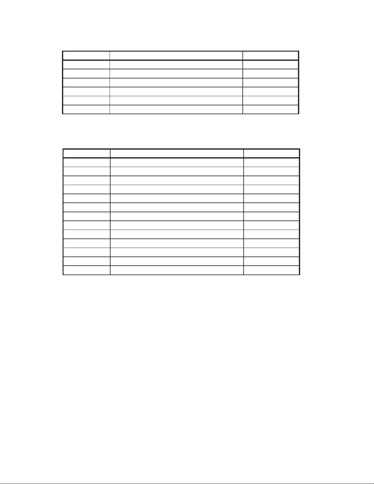
Wiring Instructions:
The beacon is terminated with a 12" long 6-wire cable harness that may be connected as follows:
COLOR FUNCTION CONNECT TO
Red Power +VDC
Black Ground Chassis ground
White Pattern switching Chassis ground to activate
Yellow
Green
Violet
Synchronization
Failure mode detect
Dim
See synchronization below
See failure mode detect below
+VDC to activate
Operation:
Synchronization:
To synchronize multiple beacons, congure as noted below. A maximum of 8 lights may be synchronized.
- To congure the beacons to ash their patterns simultaneously, advance the pattern for each beacon to Phase
0 mode of the chosen pattern. Connect the YELLOW wires from each beacon together. When the beacons are
activated, their patterns will ash together.
- To congure the beacons to alternate their patterns, advance the pattern of either beacon (but not both) to the
Phase 1 mode of the chosen pattern.
Failure Mode Detect:
This feature activates when +VDC is connected to the beacon. The following conditions are checked:
- Input voltage is at an adequate level to fully operate the beacon.
- The beacon's micro-processor is operating.
When the above are satised, the green wire is switched to ground and will support a current load up to 250
milli-amps. The green wire may serve to control an Indicator Light connected to +VDC that activates when the
beacon is ON and is functioning. The indicator light is not provided with the beacon.
Setting the Flash Pattern:
Momentarily connect the WHITE wire to chassis ground as follows:
- For the NEXT pattern; release contact when beacon ashes ON (less than 2 seconds)
- For the PREVIOUS pattern; release contact when beacon ashes ON then OFF (2 to 4 seconds)
- For the DEFAULT pattern; release contact when beacon ashes ON then OFF then ON again (greater
than 4 seconds)
8
Page 9

Maintenance:
The beacons are designed to be maintenance free. Refer to the guide below for help with troubleshooting.
Should the unit be diagnosed as malfunctioning, remove unit and replace with a new beacon.
LED beacon housings may become hot with extended use. Allow beacons to cool completely
WARNING!
Problem Probable Cause Remedy
Beacon does not activate a. No power to unit a. Check wire for loose connection
Beacon is constantly ON a. Control wire permanently
before attempting to remove.
TROUBLESHOOTING
b. Power input wire reversed b. Reverse power wires
c. Damaged or shortaged cabling c. Check cables for damage
d. Defective beacon d. Replace beacon module
a. Avoid permanent grounding of
grounded or shorted to GND
control wire
9
Page 10

Notes:
10
Page 11

Notes:
11
Page 12

WARRANTY
Code 3, Inc.'s L.E.D. emergency devices are tested and found to be operational at the time of manufacture.
Provided they are installed and operated in accordance with manufacturer's recommendations, Code 3, Inc. guarantees
all parts and components except the lamps to a period of 1 year, LED Lighthead modules to a period of 5 years (unless
otherwise expressed) from the date of purchase or delivery, whichever is later. Units demonstrated to be defective
within the warranty period will be repaired or replaced at the factory service center at no cost.
Use of lamp or other electrical load of a wattage higher than installed or recommended by the factory, or use
of inappropriate or inadequate wiring or circuit protection causes this warranty to become void. Failure or destruction
of the product resulting from abuse or unusual use and/or accidents is not covered by this warranty. Code 3, Inc.
shall in no way be liable for other damages including consequential, indirect or special damages whether loss is due
to negligence or breach of warranty.
CODE 3, INC. MAKES NO OTHER EXPRESS OR IMPLIED WARRANTY INCLUDING, WITHOUT LIMITATION, WARRANTIES OF FITNESS OR MERCHANTABILITY, WITH RESPECT TO THIS PRODUCT.
PRODUCT RETURNS
If a product must be returned for repair or replacement*, please contact our factory to obtain a Return
Goods Authorization Number (RGA number) before you ship the product to Code 3, Inc. Write the RGA number
clearly on the package near the mailing label. Be sure you use sufcient packing materials to avoid damage to
the product being returned while in transit.
*Code 3, Inc. reserves the right to repair or replace at its discretion. Code 3, Inc. assumes no responsibility or liability for expenses incurred for the removal and /or
reinstallation of products requiring service and/or repair.; nor for the packaging, handling, and shipping: nor for the handling of products return to sender after the service has been
rendered.
PROBLEMS OR QUESTIONS? CALL OUR TECHNICAL ASSISTANCE HOTLINE (314) 996-2800
or visit WWW.CODE3PSE.COM, select C3 FORUM and put your question on the forum
St. Louis, Missouri 63114-2029—USA
Ph. (314) 426-2700 Fax (314) 426-1337
10986 N. Warson Road
www.code3pse.com
Code 3, Inc.
Code 3® is a registered trademark of Code 3, Inc., a subsidiary of Public Safety Equipment, Inc.
12
Revision 1, 08/12 - Instruction Book Part No. T51315
©2012 Public Safety Equipment, Inc. Printed in USA
 Loading...