

Page 1
INSTALLATION
& OPERATION
MANUAL
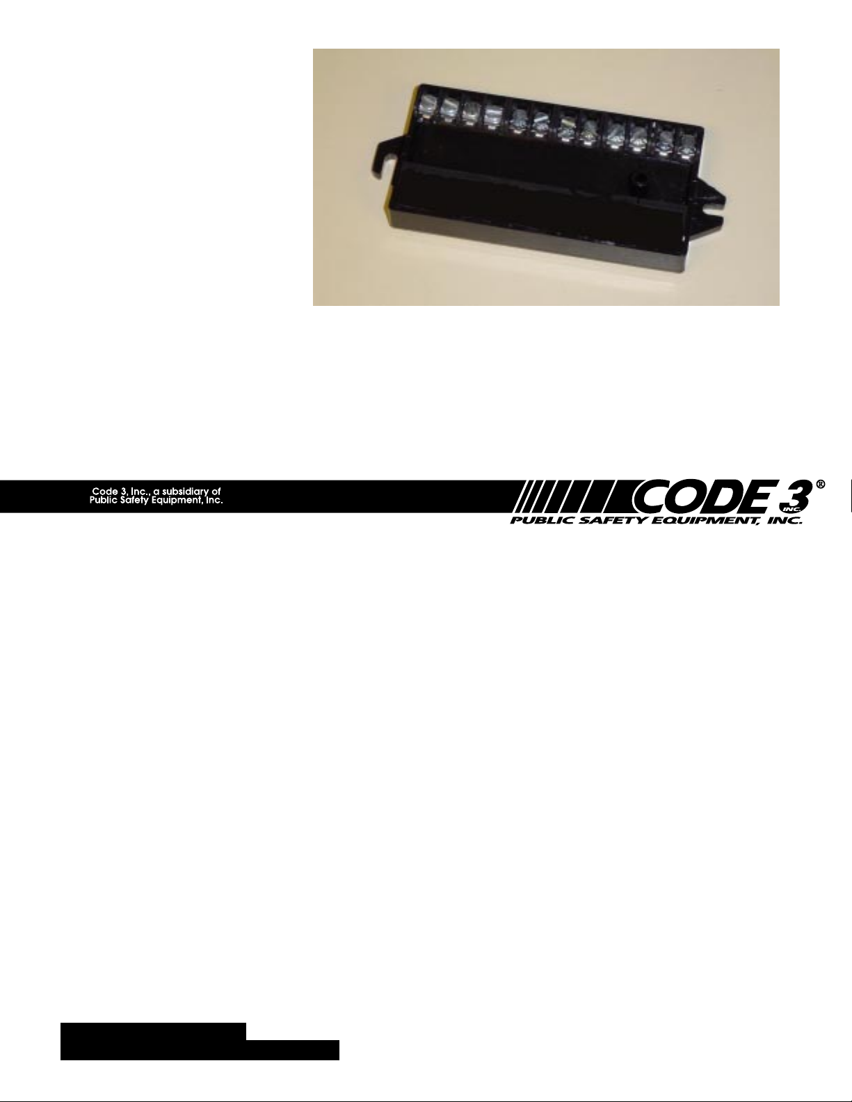
MODELS 930 & 940
FLASHERS
MODELS 930 & 940 FLASHERS
Contents:
Introduction.........................................................2
Unpacking & Pre-Installation.............................. 2
Installation & Mounting ....................................... 3
Terminal Functions ............................................. 3
Flasher Installation ............................................. 4
Testing the Flasher.............................................6
Warranty .............................................................8
IMPORTANT:
Read all instructions and warnings before installing and using.
INSTALLER: This manual must be delivered to the end user of this equipment.
1
Page 2

Introduction
The Code 3® Model 930 and 940 flashers are postiive output solid state flashers. Both models are
designed for use inside light bars and other flasher applications which require SAE and CA Title 13
compliant flash rates. Both flashers provide advanced features for ease of installation and operation.
The 930 flasher has two outputs which flash alternately (Wig/Wag) at 90 flashes per minute (FPM) and
has a Steady Burn Override and Disable inputs. The 940 flasher is a dual two output flasher. Each set of
outputs flash alternately (Wig/Wag) at 90 flashes per minute (FPM) with separate Steady Burn Overrride
inputs for each and a Disable input terminal which disables the flasher when active.
The use of this or any warning device does not insure that all drivers can or will observe or
react to an emergency warning signal. Never take the right-of-way for granted. It is your
responsibility to be sure you can proceed safely before entering an intersection, driving
against traffic, responding at a high rate of speed, or walking on or around traffic lanes.
!
WARNING!
The effectiveness of this warning device is highly dependent upon correct mounting and
wiring. Read and follow the manufacturer’s instructions before installing or using this
device. The vehicle operator should insure daily that all features of the device operate
correctly. In use, the vehicle operator should insure the projection of the warning signal is
not blocked by vehicle components (i.e.: open trunks or compartment doors), people,
vehicles, or other obstructions.
This equipment is intended for use by authorized personnel only. It is the user’s responsibility to understand and obey all laws regarding emergency warning devices. The user
should check all applicable city, state and federal laws and regulations.
Public Safety Equipment, Inc., assumes no liability for any loss resulting from the use of
this warning device.
Proper installation is vital to the performance of this warning device and the safe operation
of the emergency vehicle. It is important to recognize that the operator of the emergency
vehicle is under psychological and physiological stress caused by the emergency situation.
The warning device should be installed in such a manner as to: A) Not reduce the output
performance of the system, B) Place the controls within convenient reach of the operator
so that he can operate the system without losing eye contact with the roadway.
Emergency warning devices often require high electrical voltages and/or currents. Properly
protect and use caution around live electrical connections. Grounding or shorting of
electrical connections can cause high current arcing, which can cause personal injury and/
or severe vehicle damage, including fire. Incandescent lamps are extremely hot, allow to
cool completely before attempting to remove.
Any electronic device may create or be affected by electromagnetic interference. After
installation of any electronic device operate all equipment simultaneously to insure that
operation is free of interference. Never power emergency warning equipment from the
same circuit or share the same grounding circuit with radio communication equipment.
PROPER INSTALLATION COMBINED WITH OPERATOR TRAINING IN THE PROPER
USE OF EMERGENCY WARNING DEVICES IS ESSENTIAL TO INSURE THE SAFETY
OF EMERGENCY PERSONNEL AND THE PUBLIC.
Unpacking & Pre-installation
After unpacking your 930 or 940 Flasher, carefully inspect the unit and associated parts for any damage that
may have been caused in transit. Report any damage to the carrier immediately.
All devices should be mounted in accordance with the manufacturer's instructions and
securely fasten to vehicle elements of sufficient strength to withstand the forces applied to
!
WARNING!
the device. Driver and/or passenger air bags (SRS) will affect the way equipment should
be mounted. This device should be mounted by permanent installation and within the
zones specified by the vehicle manufacturer, if any. Any device mounted in the deployment area of an air bag will damage or reduce the effectiveness of the air bag and may
damage or dislodge the device. Installer must be sure that this device, its mounting
hardware and electrical supply wiring does not interfere with the air bag or the SRS wiring
or sensors. Front or rear grille/bumper placement must avoid interference with SRS
sensors. Mounting the unit inside the vehicle by a method other than the permanent
installation is not recommended as unit may become dislodged during swerving, sudden
braking, or collision. Failure to follow instructions can result in personal injury.
2
Page 3

Installation & Mounting
Mounting Methods
The units can be mounted using either the mounting tabs located at each end of the unit or the mounting
hole through the unit.
Larger wires and tight connections will provide longer service life for components. For high
current wires it is highly recommended that terminal blocks or soldered connections be used
with shrink tubing to protect the connections. Do not use insulation displacement
!
WARNING!
connectors (e.g. 3M® Scotchlock type connectors). Route wiring using grommets and
sealant when passing through compartment walls. Minimize the number of splices to
reduce voltage drop. High ambient temperatures (e.g. underhood) will significantly reduce
the current carrying capacity of wires, fuses, and circuit breakers. Use "SXL" type wire in
engine compartment. All wiring should conform to the minimum wire size and other
recommendations of the manufacturer and be protected from moving parts and hot
surfaces. Looms, grommets, cable ties, and similar installation hardware should be used to
anchor and protect all wiring.
Fuses or circuit breakers should be located as close to the power takeoff points as possible
and properly sized to protect the wiring and devices.
Particular attention should be paid to the location and method of making electrical
connections and splices to protect these points from corrosion and loss of conductivity.
Ground terminations should only be made to substantial chassis components, preferably
directly to the vehicle battery.
The user should install a fuse sized to approximately 125% of the maximum Amp capacity
in the supply line to protect against short circuits. For example, a 30 Amp fuse should
carry a maximum of 24 Amps. DO NOT USE 1/4" DIAMETER GLASS FUSES AS THEY
ARE NOT SUITABLE FOR CONTINUOUS DUTY IN SIZES ABOVE 15 AMPS. Circuit
breakers are very sensitive to high temperatures and will "false trip" when mounted in hot
environments or operated close to their capacity.
CAUTION: The units must be mounted away from heat sources and water splashes.
Terminal Functions
Terminal 1- Disable: All Outputs OFF.
When activated by +12VDC through a user supplied switch, all outputs will turn off as long as terminal 1
remains powered. Connect to vehicle low beam circuit to defeat flasher at night. This is an OPTIONAL
connection.
Terminal 2 - Flash: Activated by +12VDC.
When activated by +12VDC through a user supplied switch, the unit alternately flashes output terminals 9
and 10 at a 90 flash per minute rate.
Terminal 3 - Steady Burn: Output on terminal 10 is ON.
When activated by +12VDC through a user supplied switch, output will turn on in steady burn mode.
Terminal 4 - Steady Burn: Output at terminal 9 is ON.
When activated by +12VDC through a user supplied switch, output will turn on in steady burn mode.
Terminal 5 - Flash: Activated by +12VDC. (Model 940 only)
When activated by +12VDC through a user supplied switch, the unit alternately flashes output terminals 6
and 7 at a 90 flash per minute rate.
Terminal 6 - Output 1: 8 amps Maximum (Model 940 only).
Terminal 7 - Output 2: 8 amps Maximum (Model 940 only).
Terminal 8 - Steady Burn: Outputs at terminal 6 & 7 are ON.(Model 940 only).
When activated by +12VDC through a user supplied switch, outputs will turn on in steady burn mode.
Terminal 9 - Output 1: 8 amps Maximum.
3
Page 4

Terminal 10 - Output 2: 8 amps Maximum.
Terminal 11- To Battery Negative (-).
Provides the unit with ground (earth) to complete the circuit. For best results, connect directly to the
negative (-) terminal of the battery, or in light bar applications, connect to the light bar frame ground
(earth).ro
tect all wiring.
Terminal 12- Battery Positive (+12VDC).
Supplies Outputs +12VDC. The Unit should be fused with a user supplied 20 amp. fuse and wired with
#14 AWG wire minimum.
Flasher Installation
Flasher Installation (Model 930)
To install the Model 930 as an Alley Light flasher, refer to Figure 1 while following the steps below:
NOTE: Use #14 AWG wire (minimum) for all connections.
1) Mount the Flasher Unit in a convenient location inside the light bar or in the trunk (or console)
near the lighting control switch box.
2) Locate the +12V supply wire inside the light bar (or near the lighting control switch box) and
connect a 20 amp. fuse and holder in-line between the +12V source and Terminal 12 of the
Flasher Unit.
CAUTION: Leave the fuse out of the fuse holder until ready to test the circuit.
3) Install a user supplied switch in a convenient location near the driver.
4) Connect the user supplied switch between the positive source (+12VDC) and Terminal 2 of
the Flasher Unit.
5) Connect the Right Alley Light to Terminal 10 of the Flasher Unit.
6) Connect the Left Alley Light to Terminal 9 of the Flasher Unit.
7) (OPTIONAL) Connect the vehicle’s low beam switch to Terminal 1 of the Flasher Unit.
)/$6+(5',6$%/(
-
-
-
-
)/$6+(52 1
5,*+7$//(<67($'<%851
/()7$//(<67($'<%851
/HIW$OOH \
-
-
-
-
5LJKW$OOH\
2$03)86 (
%$77(5<
$:*0, 1
FIGURE 1: WIRING DIAGRAM FOR 930
LIGHT BAR FLASHER INSTALLATION
4
Page 5

NOTE: For continued Alley light flash while in low beam, do not connect Terminal 1.
8) Connect the negative (-) post of the battery, or other good ground(earth), to Terminal 11 of the
Flasher Unit.
9) Connect a user supplied switch between the positive (+12VDC) source and Terminal 3 of the
Flasher Unit. This switch will override the flash feature and cause the Left Alley Light
to operate in steady burn mode.
10 ) Connect a user supplied switch between the positive (+12VDC) source and Terminal 4 of the
Flasher Unit. This switch will override the flash feature and cause the Right Alley Light
to operate in steady burn mode.
If you are installing the Model 930 flasher, proceed to Testing the Flasher on Page 6. If you are installing
flasher Model 940 continue with step 11 below.
Continued Flasher Installation (Model 940)
To install the Model 940 as a Takedown / Alley Light flasher, complete the above outlined steps and then
refer to Figure 2 for the following steps:
11 ) Connect the Right Takedown Light to Terminal 7 of the Flasher Unit.
12 ) Connect the Left Takedown Light to Terminal 6 of the Flasher Unit.
13 ) Connect a user supplied switch between the positive (+12VDC) source and Terminal 5 of the
Flasher Unit.
14 ) Connect a user supplied switch between the positive (+12VDC) source and Terminal 8 of the
Flasher Unit. This switch will override the Takedown flash feature and cause the Takedown
Lights to operate in steady burn mode.
Double check all of your connections then refer to the section on testing the circuit.
',6$%/(&872))
$//(</,*+76)/$6+(1$%/(
-
-
-
-
7$.('2:1/,*+7$
-
-
-
-
-
-
-
-
$//(</,*+7$67($'<%851
$//(</,*+7%67($'<%851
7$.('2:1)/$6+(1$%/(
7$.('2:1/,*+7%
7$.('2:167($'<%8 51
$//(<
2$03)86(
$:*0,1
%$77(5<
/,*+7$ /,*+7%
FIGURE 2: WIRING DIAGRAM FOR 940
LIGHT BAR FLASHER INSTALLATION
5
$//(<
Page 6

Testing the Flasher
Testing the 930 Flasher
1) Install the 20 amp. fuse in the in-line fuse holder.
2) Turn ON the switch connected to terminal 2. The Alley lights will flash (Wig/Wag) at 90
FPM.
3) Turn ON the switch connected to terminals 3. The Right Alley light will change to steady
burn mode.
4) Turn ON the switch connected to terminals 4. The Left Alley light will change to steady
burn mode.
If the flasher functions do not work according to the above description, recheck all of your connections.
Testing the 940 Flasher
Steps 1-4 above also apply to the 940 flasher. Complete steps 1-4 and then proceed to step 5
below.
5) Turn ON the switch connected to terminal 5. The Takedown lights will flash (Wig/Wag) at 90
FPM.
6) Turn ON the switch connected to terminals 8. The Takedown Lights will change to steady
burn mode.
If the flasher functions do not work according to the above description, recheck all of your connections.
NOTE: If you connected Terminal 1, the flasher will stop flashing when you turn on the low beams
headlights. If you want the flasher to continue to flash, DO NOT connect Terminal 1.
6
Page 7

NOTES
7
Page 8

WARRANTY
Code 3, Inc.'s emergency devices are tested and found to be operational at the time of
manufacture. Provided they are installed and operated in accordance with manufacturer's
recommendations, Code 3, Inc. guarantees all parts and components except the lamps to a period
of 1 year (unless otherwise expressed) from the date of purchase or delivery, whichever is later.
Units demonstrated to be defective within the warranty period will be repaired or replaced at the
factory service center at no cost.
Use of lamp or other electrical load of a wattage higher than installed or recommended by the
factory, or use of inappropriate or inadequate wiring or circuit protection causes this warranty to
become void. Failure or destruction of the product resulting from abuse or unusual use and/or
accidents is not covered by this warranty. Code 3, Inc. shall in no way be liable for other damages
including consequential, indirect or special damages whether loss is due to negligence or breach of
warranty.
CODE 3Ò, INC. MAKES NO OTHER EXPRESS OR IMPLIED WARRANTY INCLUDING,
WITHOUT LIMITATION, WARRANTIES OF FITNESS OR MERCHANTABILITY, WITH RESPECT TO THIS PRODUCT.
PRODUCT RETURNS
If a product must be returned for repair or replacement*, please contact our factory to obtain
a Return Goods Authorization Number (RGA number) before you ship the product to Code 3,
Inc. Write the RGA number clearly on the package near the mailing label. Be sure you use
sufficient packing materials to avoid damage to the product being returned while in transit.
*Code 3, Inc. reserves the right to repair or replace at its discretion. Code 3, Inc. assumes no responsibility or liability for expenses incurred for the
removal and /or reinstallation of products requiring service and/or repair.; nor for the packaging, handling, and shipping: nor for the handling of products return to
sender after the service has been rendered.
For Technical Support / Service, please call 314-996-2800.
Code 3, Inc. is a registered trademark of Public Safety
Equipment, Inc.
Public Safety Equipment, Inc.
St. Louis, Missouri 63114-2029USA
Ph. (314) 426-2700 Fax (314) 426-1337
Revision 0, 5/2006 - Instruction Book Part No. T11436
©2006 Public Safety Equipment, Inc. Printed in USA
10986 N. Warson Road
www.code3pse.com
 Loading...