

Page 1
INSTALLATION MANUAL
920-07TH Headlight Flasher for 2007920-07TH Headlight Flasher for 2007
920-07TH Headlight Flasher for 2007
920-07TH Headlight Flasher for 2007920-07TH Headlight Flasher for 2007
Chevy Tahoe Police Package VehicleChevy Tahoe Police Package Vehicle
Chevy Tahoe Police Package Vehicle
Chevy Tahoe Police Package VehicleChevy Tahoe Police Package Vehicle
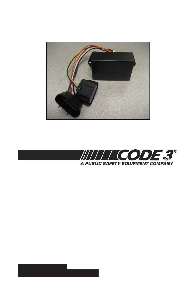
900 Series Plug In Flasher
Read all instructions and warnings before installing and using.
IMPORTANT:
INSTALLER: This manual must be delivered
to the end user of this equipment.
Page 2

W ARNING!
Larger wires and tight connections will provide longer service life
for components. For high current wires it is highly recommended
that terminal blocks or soldered connections be used with shrink
WARNING!
tubing to protect the connections. Do not use insulation displacement connectors (e.g. 3M®) Scotchlock type connectors. Route
wiring using grommets and sealant when passing through
compartment walls. Minimize the number of splices to reduce
voltage drop. High ambient temperatures (e.g. underhood) will
significantly reduce the current carrying capacity of wires, fuses,
and circuit breakers. Use "SXL" type wire in engine compartment.
All wiring should conform to the minimum wire size and other
recommendations of the manufacturer and be protected from
moving parts and hot surfaces. Looms, grommets, cable ties,
and similiar installation hardware should be used to anchor and
protect all wiring.
This Product contains high intensity LED
devices. To prevent eye damage, DO NOT
stare into light beam at close range.
Fuses or circuit breakers should be located as close to the power
takeoff points as possible ad properly sized to protect the wiring
and devices. Particular attention should be paid to the location
and method of making electrical connections and splices to
protect these points from corrosion and loss of conductivity.
Ground (Earth) termination should only be made to substantioal
chassis components, preferably directly to the vehicle battery.
The user should install a circuit breaker sized to approximately
125% of the anticipated maximum current requirements to
protect against short circuits. For example, a 30 Amp circuit
breaker should carry a maximum of 24 amps.
DO NOT USE 1/4" DIAMETER GLASS FUSES AS THEY ARE NOT
SUITABLE FOR CONTINUOUS DUTY IN SIZES ABOVE 15 AMPS.
Circuit breakers are very sensitive to high temperatures and will
"false trip" when mounted in hot environments or operated close
to their capacity.
!
2
Page 3
IMPORTANT NOTES:
••
• The use of a flashing headlight system may be regulated by state,
••
county, or municipal authorities. It is the responsibility of the end user
to comply with these regulations.
••
• Before attempting the installation of the 920 headlight flasher, thoroughly
••
read and understand instructions and steps shown below.
••
• Disconnect the battery from the electrical system
••
before attempting any part of this installation.
••
• Have your “Tahoe Police Package Owner’s Manual Supplement”
••
available for reference.
Installation:
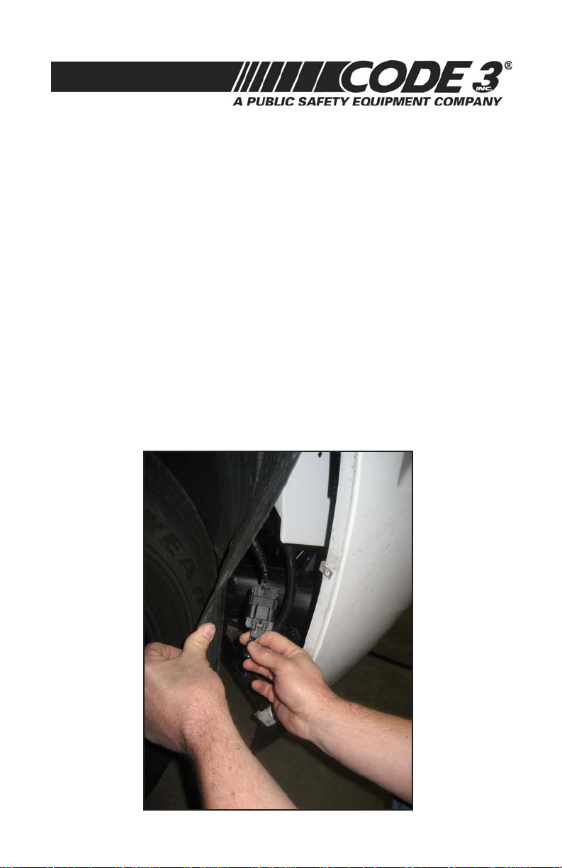
1. Locate and remove the passenger side inner fender fasteners that
secure the inner fender covering the area that the flasher connectors are located. Remove or pull back this panel to gain access. Fig 1
NOTE: Each fastener must be returned to its original location when re-
installing this panel.
Fig. 1
3
Page 4
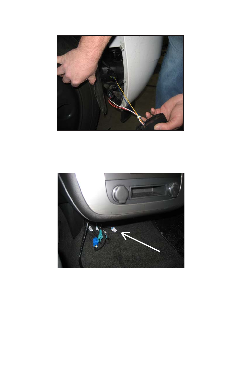
3. Locate the connectors shown in Fig 1. Disconnect these connectors
and connect the flashers connectors in line. Fig 2.
Fig. 2
4. Mount the flasher in this area using two screws (user supplied).
5. Locate the DARK GREEN/RED, 16-guage control wire under the center
dash section. Fig 3
Fig. 3
6. Connect this DARK GREEN/RED wire to a customer supplied switch (12V
activation).
4
Page 5

NOTES
5
Page 6

NOTES
6
Page 7

NOTES
7
Page 8

WARRANTY
Code 3, Inc.'s L.E.D. emergency devices are tested and found to be
operational at the time of manufacture. Provided they are installed and
operated in accordance with manufacturer's recommendations, Code 3, Inc.
guarantees all parts and components to a period of 5 years (unless otherwise
expressed) from the date of purchase or delivery, whichever is later. Units
demonstrated to be defective within the warranty period will be repaired or
replaced at the factory service center at no cost.
Use of inappropriate or inadequate wiring or circuit protection causes
this warranty to become void. Failure or destruction of the product resulting
from abuse or unusual use and/or accidents is not covered by this warranty.
Code 3, Inc. shall in no way be liable for other damages including consequential,
indirect or special damages whether loss is due to negligence or breach of
warranty.
CODE 3, INC. MAKES NO OTHER EXPRESS OR IMPLIED WARRANTY
INCLUDING, WITHOUT LIMITATION, WARRANTIES OF FITNESS OR MERCHANTABILITY, WITH RESPECT TO THIS PRODUCT.
PRODUCT RETURNS
If a product must be returned for repair or replacement*, please contact
our factory to obtain a Return Goods Authorization Number (RGA number)
before you ship the product to Code 3, Inc. Write the RGA number clearly on
the package near the mailing label. Be sure you use sufficient packing materials
to avoid damage to the product being returned while in transit.
*Code 3, Inc. reserves the right to repair or replace at its discretion. Code 3, Inc. assumes no
responsibility or liability for expenses incurred for the removal and /or reinstallation of products requiring
service and/or repair.; nor for the packaging, handling, and shipping: nor for the handling of products return to
sender after the service has been rendered.
PROBLEMS OR QUESTIONS? CALL OUR TECHNICAL ASSISTANCE HOTLINE (314) 996-2800
WWW.CODE3PSE.COM
10986 N. Warson Road
Part No. T16207 Rev. 0 4/2007
©2007 Code 3, Inc
Ph. (314) 426-2700 Fax (314) 426-1337
Code 3® is a registered trademark of Code 3, Inc., a subsidiary of Public Safety Equipment, Inc.
St. Louis, Missouri 63114-2029—USA
8
Code 3®, Inc.
 Loading...