

Page 1
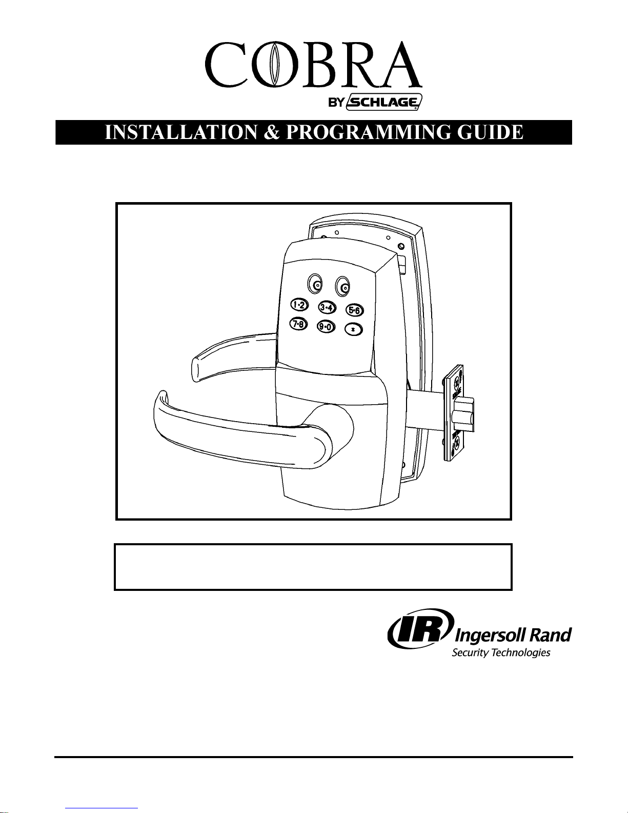
51120-D
MPC COBRA SERIES
Manually Programmable Cylindrical Lock
57010-H 12-19-2005
575 Birch Street
Forestville, CT 06010
technical support: 866-322-1237
fax: 866-322-1233
http://www.irsupport.net
Page 2

COBRA INSTALLATION AND PROGRAMMING GUIDE
Introduction / Tools and Materials Needed
COBRA INSTALLATION AND PROGRAMMING GUIDE
Introduction / Tools and Materials Needed
Introduction
The MPC Cobra is a battery-powered manually programmed access control system. Up to 100 individual codes can be programmed right at the keypad. A red and
green LED on the keypad provide visual indication for programming and access
events. Mechanical key override is possible when a 7-pin small-format interchangeable core (not included) is installed in place of the cylinder plug, which
comes standard. Either the plug or the IC core must be installed for the lock to
operate. When the cylinder is removed (using the cylinder control key) the lock
will unlock. Manual key override should only be necessary if the low battery output indications have been ignored. (See also
BATTERY INFORMATION: on page 10).
The design allows for mounting on doors from 1-1/2” to 2” thick. A shim is available to mount the lock to a 1-3/8” door. An exterior gasket (EG option) is available
for application to exterior sides of doors.
Tools and Materials Needed
1. Philips head screwdriver set
2. Allen wrench set
3. Loctite 242
4. 4 “AA” Batteries (provided)
The following will also be needed only for new installations:
5. Full size door template (provided)
6. Pencil
7. Center Punch
8. Hammer
9. Chisel
10. Square
11. Level
12. Masking tape
13. Drill w/chuck for up to 1” drill bits
14. Drill bit set
15. 2-1/8” Hole saw
57010-H Page 2 12-19-2005
Page 3
COBRA INSTALLATION AND PROGRAMMING GUIDE
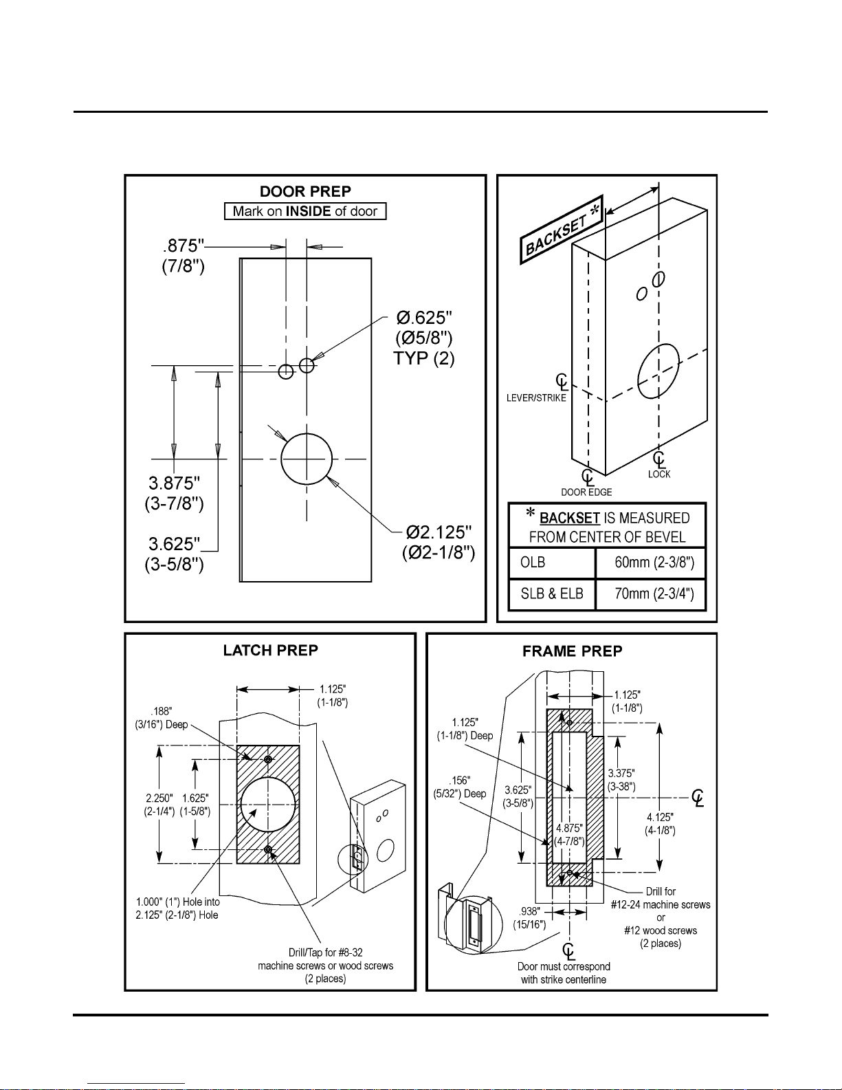
Frame and Door Preparation for Lock
Frame and Door Preparation for Lock
Frame and Door Preparation for Lock
57010-H Page 3 12-19-2005
Page 4
COBRA INSTALLATION AND PROGRAMMING GUIDE
ike b
h
O
Installing the Cobra
Installing the Cobra
Installing the Cobra
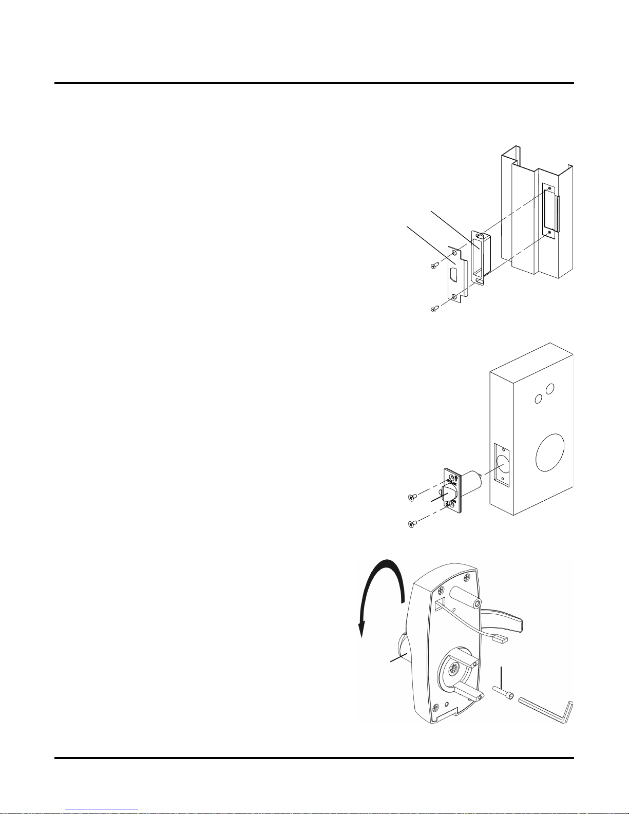
1) Install the Strike Components into the Door Frame:
• Insert str
• Place strike (b) over strike box.
• Secure in place with 2 screws.
ox (a) into door frame.
2) Install the Cylindrical Latch:
• Insert t
NOTE: Sloped side of latch (a) should face door strike.
• Secure in place with 2 screws.
e cylindrical latch into the edge of the door.
a
b
a
3) Change Handing if Necessary:
utside escutcheon is shown in figure.
• Remove and retain 5/32” socket cap screw (a).
• Remove lever.
• Rotate lever (b) to opposite position.
• Apply thread lock compound * to screw.
• Reinstall screw.
• Repeat for inside escutcheon (not shown).
• * Loctite 242 is recomended.
57010-H Page 4 12-19-2005
b
a
Page 5

COBRA INSTALLATION AND PROGRAMMING GUIDE
d
he insid
lid
18” hol
ll l
4) Remove the Latch Guard From the Retractor:
Installing the Cobra
• Remove an
the latch guard to the retractor.
• Remove and retain the latch guard.
retain the screw that secures
5) Install the Retractor:
• From t
IMPORTANT: Make sure latch tabs engage with retractor jaws.
See Detail A.
e of the door, s
e retractor (a) into 2-
e.
outside
inside
a
6) Install the Latch Guard:
• Insta
• Secure latch guard with screw.
57010-H Page 5 12-19-2005
atch guard (a) onto retractor.
outside
a
inside
Page 6

COBRA INSTALLATION AND PROGRAMMING GUIDE
Ob
Installing the Cobra
7) Install the Outside Escutcheon:
• If necessary, apply exterior gasket (EG
option) to surface (a).
• Insert the round end of the spindle* (b)
into the outside escutcheon’s hub
assembly (c).
• Dot on cam (d) must be at the 6 o’clock
(bottom) position.
• From outside of door, feed outside
escutcheon’s battery wire harness (e)
through hole (f) in door.
• Slide escutcheon against door.
Refer to the chart below to determine the
correct spindle to use.
a
d
f
e
c
b
*
8) Install the Inside Baseplate Assembly:
•
• From inside of door, feed battery wire harness (b) through hole
• Feed battery wire harness through hole in inside baseplate
• Press baseplate (and spacer, if there is one) against door.
serve the polarity markings inside the battery holder (a) and
install the 4, AA batteries (provided) accordingly.
in spacer (c) if needed *.
assembly (d).
*
Spacer required on doors thinner than 1-1/2”.
spacer required on doors thinner than 1-1/2”
Order P/N: MPC-SK
57010-H Page 6 12-19-2005
b
d
c
a
Page 7

COBRA INSTALLATION AND PROGRAMMING GUIDE
Appl
242
*
C
9) Secure the Baseplate:
Installing the Cobra
•
• Secure the baseplate with the three screws.
y Loctite
to the three provided baseplate screws.
10) Install the Inside Spindle:
• Install spring (a) into spindle (b)
• Insert square end of spindle into retractor.
.
*
b
* DOOR THICKNESS:
1-3/8” to 1-3/4” --- USE YELLOW SPINDLE
1-7/8” to 2” --- USE BLACK SPINDLE
11) Connect the Battery:
•
onnect the battery wire harness.
a
c
b
57010-H Page 7 12-19-2005
Page 8

COBRA INSTALLATION AND PROGRAMMING GUIDE
l
Installing the Cobra
12) Install the Inside Escutcheon Cover:
• P
ace the inside escutcheon (a) over the inside baseplate.
• Using the spanner screw tool (pictured below), secure the
inside escutcheon cover with the 4 provided spanner screws.
a
57010-H Page 8 12-19-2005
Page 9

COBRA INSTALLATION AND PROGRAMMING GUIDE
ld lock in hori
p
b
Installing the 6 or 7-Pin IC Core for Manual Key Override
Installing the 6 or 7-Pin IC Core for M anual Key Override
1) Install the 7-Pin Small-Format IC Core for Manual Key Override:
• Ho
• Remove tape (a) if present.
• Push in plug (b) until pin (c) until it falls out.
• Remove plug.
zontal position.
• Insert cylinder control key (a) into core (b) and turn
clockwise to retract locking pin.
b
a
c
b
a
• Push cylinder core into lock
NOTE: Resistance will be noticeable.
• Turn key counterclockwise to engage locking pin.
• Remove key.
Lock is now operational.
NOTE:
6-PIN IC CORE CYLINDERS REQUIRE THAT THE
ADAPTER IS INSTALLED TO MAKE THEM AS LONG
AS A 7-PIN CYLINDER. THE ADAPTER IS
INCLUDED IN THE SCREW PACK. DO NOT INSTALL
THE ADAPTER IN A 7-PIN IC CORE CYLINDER.
Operation:
Either the cylinder plug or the IC core must be installed for the lock to operate. Removal of the core or
lug automatically unlocks the lock. It is recommended that an IC core be installed in case it ever
ecomes necessary to unlock the lock using mechanical means.
57010-H Page 9 12-19-2005
Page 10

COBRA INSTALLATION AND PROGRAMMING GUIDE
CODE FUNCTIONS
Programming Lock Codes
Programming Lock Codes
The MPC Cobra is manually programmable to have up to 100 codes. The codes can have different functions as described below. Several
types of functions have factory default values which are operational as soon as the lock is installed. It is highly recommended that the Programming Code be changed (this will delete all factory default codes) and new codes be added. In addition, it is recommended that at least
one Freeze/Lockout Code be added - in case the batteries get completely drained. (See “Battery Information” on below.) All codes can be 38 digits in length (except the Programming code which must be 5-8 digits.) Keep a log of all issued codes. Issue codes exclusively with all
odd or all even numbers - this practice will make it easier to spot duplicate codes, since each keypad button represents two numbers (for
example, code 246 is identical to code 135.)
:
FUNCTION
FACTORY DEFAULT
DESCRIPTION
The programming code puts the lock into a programming mode. It will not unlock the lock.
When a Programming code plus “*” is entered the LEDs alternately flash several times
indicating the lock is in a programming mode. If more than 30 seconds pass in between
programming entries, the lock returns to a normal operational state.
XXX
Normal codes unlock the lock for the relock time delay. While the lock is unlocked the
green LED will flash. The LED will stop flashing and the lock will relock.
xxx
Toggle codes unlock the lock indefinitely. When the same (or another) toggle code is
entered, the lock will immediately relock. When a toggle code is entered, the green LED
will flash once. The LED will stop flashing and the lock will relock.
xxx
Freeze/Lockout codes prevent other codes from working. The lock can be locked or
unlocked when one is entered. If it is locked, a Pass Thru code will unlock it but all other
codes will not. Only another Lockout code will reverse the effect.
xxx
One Use codes unlock the lock for the relock time delay. They will only work once and
then are deleted from memory. They can used again if they are programmed (added) into
memory again.
Supervised codes require that two different supervised codes entered in order to unlock
the lock for the relock time delay.
xxx
Pass Thru codes will unlock the door for the relock time delay even if the door is in the
lockout mode.
BATTERY INFORMATION:
The MPC Cobra uses four, standard AA batteries.
The batteries should provide enough life for
approximately 80,000 lock/unlock cycles. When
the batteries are running out the lock provides two
different modes of low battery indication: First,
when a code is entered, the red LED will flash
twelve times before the lock executes the command of the code. This is an indication that it is
time to replace the batteries. The lock will go for
about 500 cycles in this condition. After it reaches
a certain point the lock will go into “Low Battery
Lockout” mode. A Freeze/Lockout code will need
to be entered in order gain access. If the batteries
are not changed, the lock will eventually not work
and manual key override (if installed) will need to
be used.
57010-H Page 10 12-19-2005
CLEARING MEMORY:
Clearing memory will delete all programmed codes and restore factory default
codes. If the memory ever needs to be erased follow the steps below:
1. Remove the inside escutcheon. Remove one of the batteries.
2. Press any key.
3. Hold down the “*” key and reinstall the battery. Continue holding the “*” key
down. The red LED will flash a few times and then stay on.
4. Release the “*” key.
5. Install the inside escutcheon.
Note: to return the lock to the factory default relock time delay, do steps 1-4 twice
in a row.
Page 11

Use the st
this
COBRA INSTALLATION AND PROGRAMMING GUIDE
Programming Steps
eps on
gram codes into the lock. The “*” key
is used like the <ENTER> key is on
a computer. After pressing the “*”
key, wait for the red and green LEDs
to stop flashing before proceeding to
the next step. If at any time the red
LED stays on while the green LED
flashes an error has occurred. The
flashing message will repeat three
times. Count the number of flashes
and consult the error code chart
below.
FLASHES ERROR CODE DESCRIPTION
2 Code too long
Maximum digits
6 • 12 button keypad
8 • 6 button keypad
page to pro-
Programming Steps
3 Memory full, delete some
codes
4 Use Change Prog. code
procedure
5 Prog. Code entries do not
match, code not changed
6 Invalid entry, start over
7 Code for deletion not found
8 Code too short
Prog. code 5 digit minimum
User Code 3 digit minimum
9 Duplicate code
57010-H Page 11 12-19-2005
Page 12

COBRA INSTALLATION AND PROGRAMMING GUIDE
Confirming the Contents of the Box
Confirming the Contents of the Box
57010-H Page 12 12-19-2005
 Loading...