

Page 1
1601 J. P. Hennessy Drive, LaVergne, TN USA 37086-3565 615/641-7533 800/688-6359 www.ammcoats.com Manual Part No.: 8113423 11
HENNESSY INDUSTRIES INC. Manufacturer of AMMCO
®
, COATS®and BADA®Automotive Service Equipment and Tools. Revision: 10/09
READ these instructions before placing unit in
service KEEP these and other materials delivered
with the unit in a binder near the machine for
ease of reference by supervisors and operators.
See
Balancing
Your First Tire
on page 2.
Installation Instructions
Operating Instructions
Safety Instructions
Maintenance Instructions
XR 1800, XR 1850
Ride Management System
®
Page 2

ii • Important: Always read and follow the on-screen operating instructions.
IMPORTANT SAFETY INSTRUCTIONS
SAVE THESE INSTRUCTIONS
READ ALL INSTRUCTIONS
1. Eye and face protection recommendations:
“Protective eye and face equipment is required to
be used where there is a reasonable probability of
injury that can be prevented by the use of such
equipment.” O.S.H.A. 1910.133(a) Protective goggles, safety glasses, or a face shield must be provided by the owner and worn by the operator of
the equipment. Care should be taken to see that
all eye and face safety precautions are followed by
the operator. ALWAYS WEAR SAFETY GLASSES.
Everyday glasses only have impact resistant
lenses, they are not safety glasses.
2. Do not disable hood safety interlock system, or in
any way shortcut safety controls and operations.
3. Be sure that wheels are mounted properly, the hub
nut engages the arbor for not less than four (4)
turns, and the hub nut is firmly tightened before
spinning the wheel.
4. Read and understand this manual before operating. Abuse and misuse will shorten the functional
life.
5. Be sure the balancer is properly connected to the
power supply and electrically grounded.
6. Do not operate equipment with a damaged cord or
if the equipment has been dropped or damaged –
until it has been examined and repaired by a qualified serviceman.
7. Do not let cord hang over edge of table, bench, or
counter or come in contact with hot manifolds or
moving fan blades.
8. If an extension cord is necessary, a cord with a current rating equal to or more than that of the equipment should be used. Cords rated for less current
than the equipment may overheat. Care should be
taken to arrange the cord so that it will not be
tripped over or pulled.
9. Keep guards and safety features in place and in
working order.
10. Wear proper clothing. Safety toe, non-slip
footwear and protective hair covering to contain
hair is recommended. Do not wear jewelry, loose
clothing, neckties, or gloves when operating the
balancer.
11. Keep work area clean and well lighted. Cluttered
and/or dark areas invite accidents.
12. Avoid dangerous environments. Do not use power
tools or electrical equipment in damp or wet locations, or expose them to rain.
13. Avoid unintentional starting. Be sure the balancer
is turned off and power disconnected before servicing.
14. Disconnect the balancer before servicing.
15. Use only manufacturer’s recommended accessories. Improper accessories may result in personal injury or property damage.
16. Repair or replace any part that is damaged or worn
and that may cause unsafe balancer operation. Do
not operate damaged equipment until it has been
examined by a qualified service technician.
17. Never overload or stand on the weight tray or any
part of the balancer.
18. Do not allow untrained persons to operate machinery.
19. To reduce the risk of fire, do not operate equipment in the vicinity of open containers or flammable liquids (gasoline).
20. Adequate ventilation should be provided when
working on or operating internal combustion
engines.
21. Keep hair, loose clothing, fingers, and all parts of
body away from moving parts.
22. Use equipment only as described in this manual.
23. Use only manufacturer’s recommended attachments and accessories.
Safety
Page 3
Important: Always read and follow the on-screen operating instructions. • iii
Owner’s Responsibility
To maintain machine and user safety, the responsibility of the owner is to read and follow these instructions:
• Follow all installation instructions.
• Make sure installation conforms to all applicable
Local, State, and Federal Codes, Rules, and
Regulations; such as State and Federal OSHA
Regulations and Electrical Codes.
• Carefully check the unit for correct initial function.
• Read and follow the safety instructions. Keep them
readily available for machine operators.
• Make certain all operators are properly trained,
know how to safely and correctly operate the unit,
and are properly supervised.
• Allow unit operation only with all parts in place and
operating safely.
• Carefully inspect the unit on a regular basis and
perform all maintenance as required.
• Service and maintain the unit only with authorized
or approved replacement parts.
• Keep all instructions permanently with the unit and
all decals/labels/notices on the unit clean and visible.
• Do not override safety features.
Operator Protective Equipment
Personal protective equipment helps make tire servicing safer. However, equipment does not take the
place of safe operating practices. Always wear durable
work clothing during tire service activity. Loose fitting
clothing should be avoided. Tight fitting leather gloves
are recommended to protect operator’s hands when
handling worn tires and wheels. Sturdy leather work
shoes with steel toes and oil resistant soles should be
used by tire service personnel to help prevent injury in
typical shop activities. Eye protection is essential during tire service activity. Safety glasses with side
shields, goggles, or face shields are acceptable. Back
belts provide support during lifting activities and are
also helpful in providing operator protection.
Consideration should also be given to the use of hearing protection if tire service activity is performed in an
enclosed area, or if noise levels are high.
Definitions of Hazard Levels
Identify the hazard levels used in this manual with the
following definitions and signal words:
DANGER
Watch for this symbol:
It Means: Immediate hazards, which will result in
severe personal injury or death.
WARNING
Watch for this symbol:
It Means: Hazards or unsafe practices, which could
result in severe personal injury or death.
CAUTION
Watch for this symbol:
It Means: Hazards or unsafe practices, which may
result in minor personal injury or product or property
damage.
Watch for this symbol! It means BE ALERT! Your
safety, or the safety of others, is involved!
CAUTION
WARNING
DANGER
Safety
Page 4
iv • Important: Always read and follow the on-screen operating instructions.
Safety
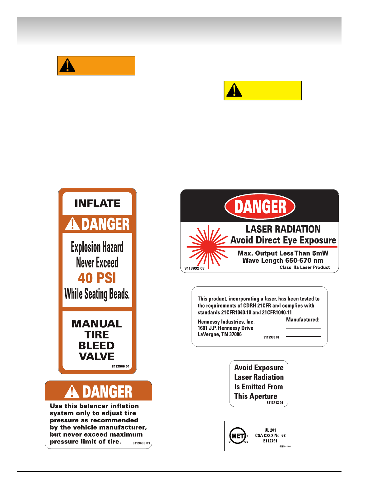
Safety Notices and Decals
Failure to follow danger, warning, and caution
instructions may lead to serious personal
injury or death to operator or bystander or
damage to property. Do not operate this
machine until you read and understand all the
dangers, warnings and cautions in this manual. For additional copies of either, or further
information, contact:
Hennessy Industries, Inc.
1601 J.P. Hennessy Drive
LaVergne, TN 37086-3565
(615) 641-7533 or (800) 688-6359
www.ammcoats.com
The Lateral Runout unit of this machine contains a
Class IIIa laser with a maximum output less than 5mW
at a wave length of 650-670 nm. Avoid Exposure -
Laser radiation is emitted from its aperture.
Use of controls, adjustments or performance
of procedures other than those specified
herein may result in hazardous radiation
exposure.
There are NO service procedures or adjustments which can be performed on the laser
in this product.
In case of failure, the entire lateral runout unit
(part no. 80180126) must be replaced.
CAUTION
WARNING
Page 5
Important: Always read and follow the on-screen operating instructions. • v
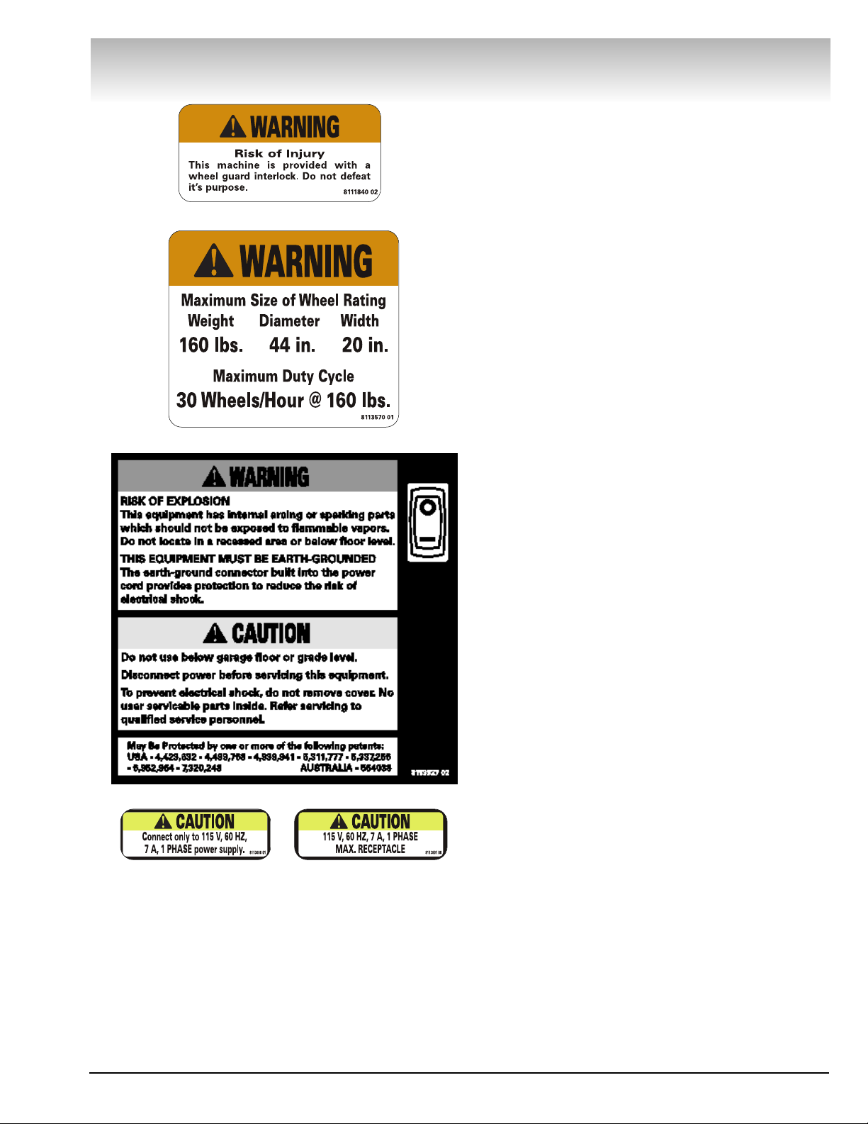
Standard Safety Devices
• Stop key for stopping the wheel under emergency
conditions.
• A hood guard of high impact plastic that is designed
to prevent the counterweights from flying out in any
direction except towards the floor.
• A hood switch interlock system that prevents the
machine from starting if the guard is not lowered and
stops the wheel whenever the guard is raised.
Safety
Page 6
NOTICE
Read entire manual before assembling,
installing, operating, or servicing this
equipment.
vi • Important: Always read and follow the on-screen operating instructions.
Safety
Page 7

Important: Always read and follow the on-screen operating instructions. • 1
Contents
Table of Contents
Important Safety Instructions . . . . . . . . . . . .ii
Owner’s Responsibility . . . . . . . . . . . . . . . . . . . . . .iii
Operator Protective Equipment . . . . . . . . . . . . . . . .iii
Definitions of Hazard Levels . . . . . . . . . . . . . . . . . .iii
Safety Notices and Decals . . . . . . . . . . . . . . . . .iv - v
Standard Safety Devices . . . . . . . . . . . . . . . . . . . . .v
Balancing Your First Tire . . . . . . . . . . . .2 - 3
Principle Operating Parts . . . . . . . . . . . . . .4 - 9
Power Switch . . . . . . . . . . . . . . . . . . . . . . . . . . . . . .6
Air Gauge Panel . . . . . . . . . . . . . . . . . . . . . . . . . . . .6
Positioning Pedal . . . . . . . . . . . . . . . . . . . . . . . . . . .6
Using the Offset Arm . . . . . . . . . . . . . . . . . . . . . . .7
Sensor Measuring Systems . . . . . . . . . . . . . . . . . . .8
Printer . . . . . . . . . . . . . . . . . . . . . . . . . . . . . . . . . . .9
Understanding the
Video Display Screens . . . . . . . . . . . . . .10 - 13
Monitor and Initial Screen Feature Reference . . . .11
Menu Screen Flowchart . . . . . . . . . . . . . . . . .12 - 13
Balancer Function
Set-up and Review . . . . . . . . . . . . . . . . .14 - 16
General Set-up . . . . . . . . . . . . . . . . . . . . . . . .14 - 15
Balancing Set-up . . . . . . . . . . . . . . . . . . . . . . . . .15
Special Functions . . . . . . . . . . . . . . . . . . . . . . . . . .15
Additional Functions . . . . . . . . . . . . . . . . . . . . . . . .16
Advanced Balancing Functions . . . . . . .16 - 19
Initial Screen Options . . . . . . . . . . . . . . . . . . .16 - 17
Dynamic Modes . . . . . . . . . . . . . . . . . . . . . . . . . . .17
Static Modes . . . . . . . . . . . . . . . . . . . . . . . . . . . . .18
Special Modes . . . . . . . . . . . . . . . . . . . . . . . . . . . .18
Additional Options . . . . . . . . . . . . . . . . . . . . . . . . .19
Matching . . . . . . . . . . . . . . . . . . . . . . . . .20 - 22
Automatic Runout Detection . . . . . . . . . . . . . . . . .20
Optimization (Match Balance) . . . . . . . . . . . . . . . .21
Runout (Runout Match) . . . . . . . . . . . . . . . . . . . . .22
Manually Setting Wheel
Dimensions (DIM) . . . . . . . . . . . . . . . . . . . . .23
Mounting Wheel on Spindle Shaft . . . .24 - 25
Standard Back Cone Mounting . . . . . . . . . . . . . . .24
Standard Front Cone Mounting . . . . . . . . . . . . . . .25
Alternate Mounting . . . . . . . . . . . . . . . . . . . . . . . .25
Machine Self-calibration and
Service Adjustments . . . . . . . . . . . . . . .26 - 29
Machine Self-calibration . . . . . . . . . . . . . . . . . . . . .26
Service Adjustments . . . . . . . . . . . . . . . . . . . . . . .27
Distance Arm Calibration . . . . . . . . . . . . . . . . . . . .27
Width Sonar Calibration (If equipped) . . . . . . .27 - 28
Diameter Arm Calibration (Plastic) . . . . . . . . . . . . .28
Diameter Arm Calibration (Metal) . . . . . . . . . . . . .29
Diagnostic Procedures . . . . . . . . . . . . . .29 - 34
After Balance Vibration Problems . . . . . . . . . . . . .29
Troubleshooting . . . . . . . . . . . . . . . . . . . . . . .30 - 33
Machine Self-Test “Green Screen” . . . . . . . . . . . .34
Maintenance Instructions . . . . . . . . . . . . . . .35
Monitor Screen Adjustment . . . . . . . . . . . . . . . . .35
Installation Instructions . . . . . . . . . . . . .36 - 37
Receiving . . . . . . . . . . . . . . . . . . . . . . . . . . . . . . . .36
Electrical Requirements . . . . . . . . . . . . . . . . . . . . .36
Setup . . . . . . . . . . . . . . . . . . . . . . . . . . . . . . . . . . .36
Air Supply Connection . . . . . . . . . . . . . . . . . . . . . .36
Connect to Power . . . . . . . . . . . . . . . . . . . . . . . . .36
Floor and Space Requirements . . . . . . . . . . . . . . .37
Specifications . . . . . . . . . . . . . . . . . . . . . . . . .38
Features . . . . . . . . . . . . . . . . . . . . . . . . . . . . .38
Required Accessories . . . . . . . . . . . . . . . . . .39
Optional Accessories . . . . . . . . . . . . . . . . . . .39
Glossary of Terms . . . . . . . . . . . . . . . . . . . . .41
1750/1800 Functional Check for
Calibration . . . . . . . . . . . . . . . . . . . .Back Cover
Page 8
2 • Important: Always read and follow the on-screen operating instructions.
Video Balancer
Balancing Your First Tire
Important: Always read and follow the on-screen
operating instructions.
1. Turn the machine OFF then ON
(resets machine).
The initial screen is in dynamic mode using standard
clip-on wheel weight locations and wheel dimensions.
2. Mount a tire/wheel on the
balancer that will use standard clipon wheel weights.
Use the most appropriate mounting method.
3. Always remove any weights
already attached to the wheel.
Use the most appropriate mounting method. Always
remove any weights attached to the wheel.
4. Enter A & D wheel dimensions
using offset arm.
For Automatic Measurement — pull the offset arm
out to the wheel, hold it still at clip-on weight position
against the wheel flange, and wait for the BEEP.
Clip-on Weight Location — viewed on a cut-away rim
for clarification.
5. Enter Width wheel dimension.
Enter Width at DIM screen or, if equipped with the
Hood Sensor System, lower the hood to automatically
measure tire width.
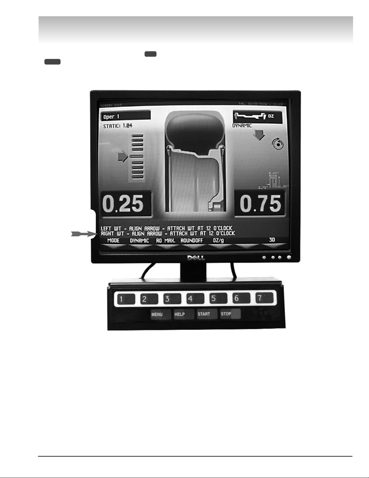
6. The wheel spins and unbalances
are measured and displayed.
The corrective weight amount appears on the video
display screen for the left and the right planes of the
wheel, see figure 3.
7. Raise hood after tire stops
rotating.
Note: If the hood is raised before the end of the spin,
an error screen will appear. Wait for the weight
amounts to display before raising the hood.
8. Rotate wheel to position left side
placement arrow at the center bar.
As illustrated in figure 3, rotate the wheel to position
the left side placement arrow at the center red bar.
Step on the positioning pedal to hold the tire in place.
9. Attach left side corrective weight
amount at top-dead center on the
inside flange of the wheel.
Attach specified corrective weight amount (0.25 oz in
figure 3) at top-dead-center on inside flange of wheel.
10. Rotate wheel to position right
side placement arrow at center bar.
Rotate the wheel to position the right side placement
arrow at the center red bar. Step on the positioning
pedal to hold the tire in place.
11. Attach the right side corrective
weight.
Attach specified weight amount (0.75 oz in figure 3) at
top-dead-center on the outside flange of the wheel.
12. Lower the hood to respin the
tire/wheel and check balance.
Your weight readings should now be 0.00.
Note: Throughout this manual tire dimensions are
referred to as A, W, and D, see figure 2.
Figure 2 - A, W, and D Tire Dimensions
Figure 1 - Automatic Measurement
Metal Offset Arm Plastic Offset Arm
Page 9
Note: To reset the mode back to the initial screen at
any time, press the DYNAMIC option or press the
key, or turn the machine OFF then ON. Note that
if an operator is in a balance mode, it may be necessary to finish the balance cycle first.
MENU
2
Figure 3 - Weight Placement Screen Using Clip-on Weights
in Dynamic Mode
Important: Always read and follow the on-screen operating instructions. • 3
Video Balancer
Important: Always
read and follow the
on-screen operating
instructions.
Page 10
4 • Important: Always read and follow the on-screen operating instructions.
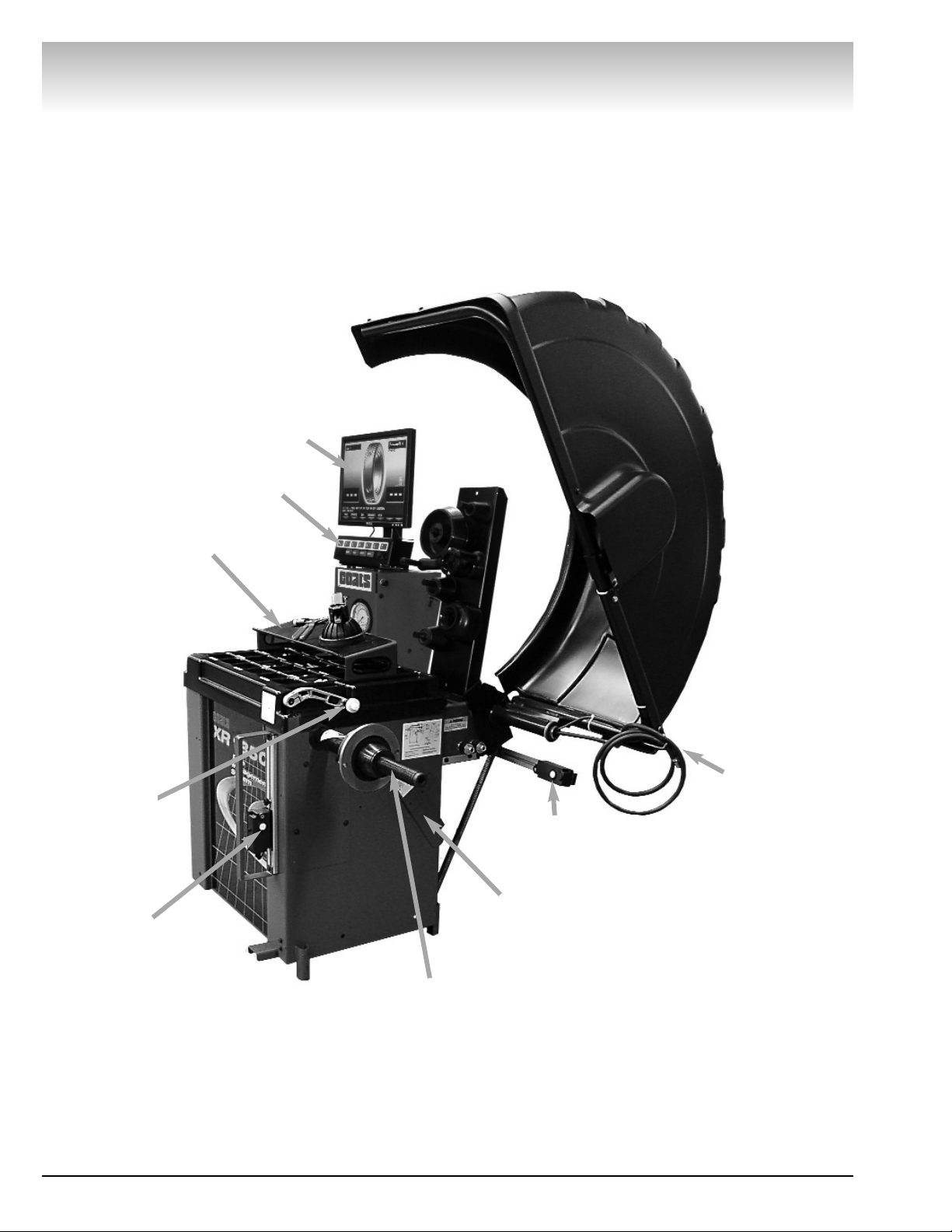
Principle Operating Parts
Video Balancer
Monitor
Portable Sliding
Storage Tray
Sensor Target Bracket
(for calibration)
40 MM Shaft
Radial Runout
Sensor (adjustable
to center of tread)
Clip-on Air
Chuck for
Tire Inflation
Adjustment
Lateral Runout
Sensor (adjustable
to sidewall of tire)
ON/OFF and
Circuit Breaker
(back of machine)
115 V UL
Approved Plug
(back of machine)
Offset Arm with
Tape-A-Weight™
Feature,
Measures A&D
of Tire/Wheel
(shown in home
position)
Touch Panel
Page 11
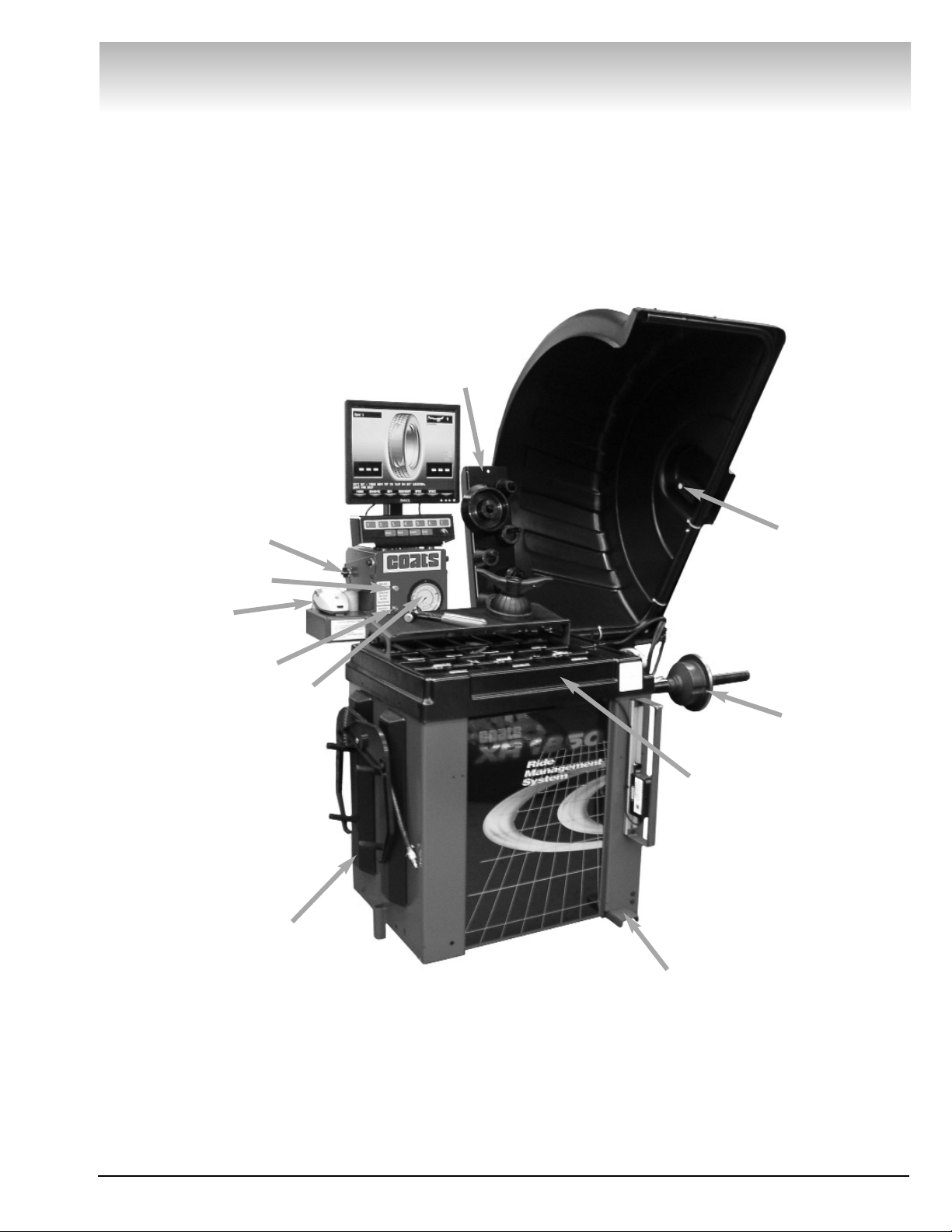
Important: Always read and follow the on-screen operating instructions. • 5
Video Balancer
Tool Accessory
Storage
Captured
Cone Spring
Printer
Protected Side
Storage Pegs for
Accessories
Positioning Pedal Holds Position for
Weight Application
Tilting Monitor
Adjustment Knobs
Adjustable
Air Gauge
Manual Tire
Bleed Valve
Inflate Button
Weight Tray with
Dual Pockets for
Weights thru 2 oz.
- Deep Pockets
thru 4 oz.
Tire Width Sensor
(measures when
hood is lowered)
Page 12
6 • Important: Always read and follow the on-screen operating instructions.
Video Balancer
Power Switch
The ON/OFF decal, see figure 4, indicates the location of the ON/OFF switch at the back of the balancer.
The circuit breaker reset button is also at this location.
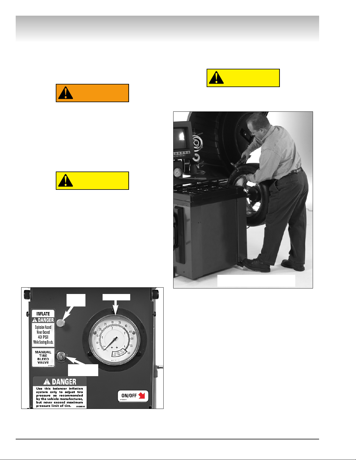
Air Gauge Panel
NEVER exceed tire manufacturer’s recommended air pressure. Tires can explode,
especially if inflated beyond these limits.
Keep hands, arms, and entire body back
from inflating tire. Avoid distraction during
inflation. Check tire pressure frequently to
avoid over inflation. Excessive pressure can
cause tires to explode, causing serious
injury or death to operator or bystander.
Do not lower the hood with the clip-on air
chuck attached to the tire’s valve stem. With
the hood start feature ON, the tire will start
rotation causing damage to the wheel and
balancer and possible personal injury.
As shown, the wheel balancer is equipped with the
capability to adjust the air pressure of the tire. The
INFLATE push button supplies air through the hose
and clip-on air chuck located at the wheel guard. When
the chuck is attached to the valve stem, air pressure is
indicated on the gauge. Excess pressure can be
reduced using the MANUAL TIRE BLEED VALVE. See
figure 4.
Figure 4 - Air Gauge Panel and ON/OFF switch decal that
indicates ON/OFF switch location at the back of
the balancer.
Positioning Pedal
Use the positioning pedal to hold the wheel position
during weight application, as shown in figure 5.
Do not actuate the positioning pedal during
the measurement cycle. Do not use the
positioning pedal as a brake.
Figure 5 - Positioning Pedal
CAUTION
CAUTION
WARNING
Air Gauge
Inflate
Button
Manual Tire
Bleed Valve
Press Positioning Pedal with
Foot to Hold Wheel Position
Page 13
Important: Always read and follow the on-screen operating instructions. • 7
Video Balancer
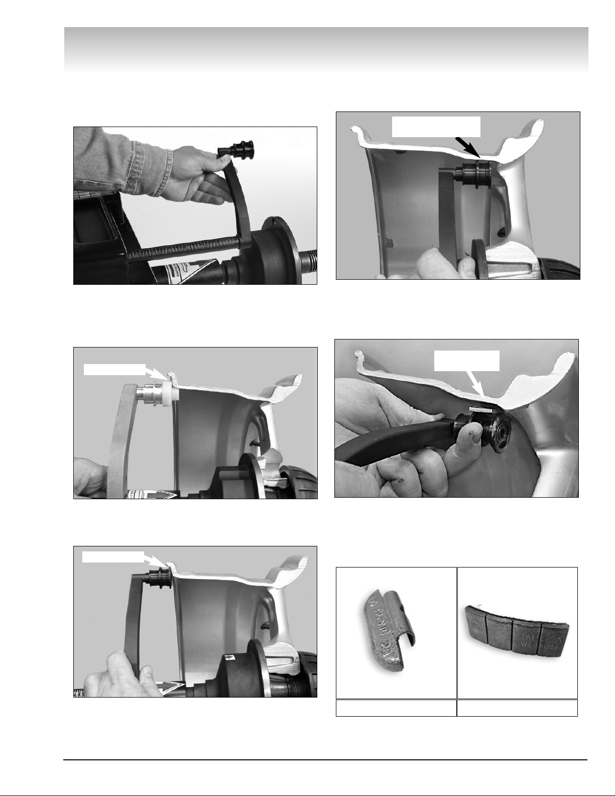
Using the Offset Arm
When prompted by the on-screen instructions, use
the offset arm, see figure 6, to enter A & D measurements automatically.
Figure 6 - Offset Arm
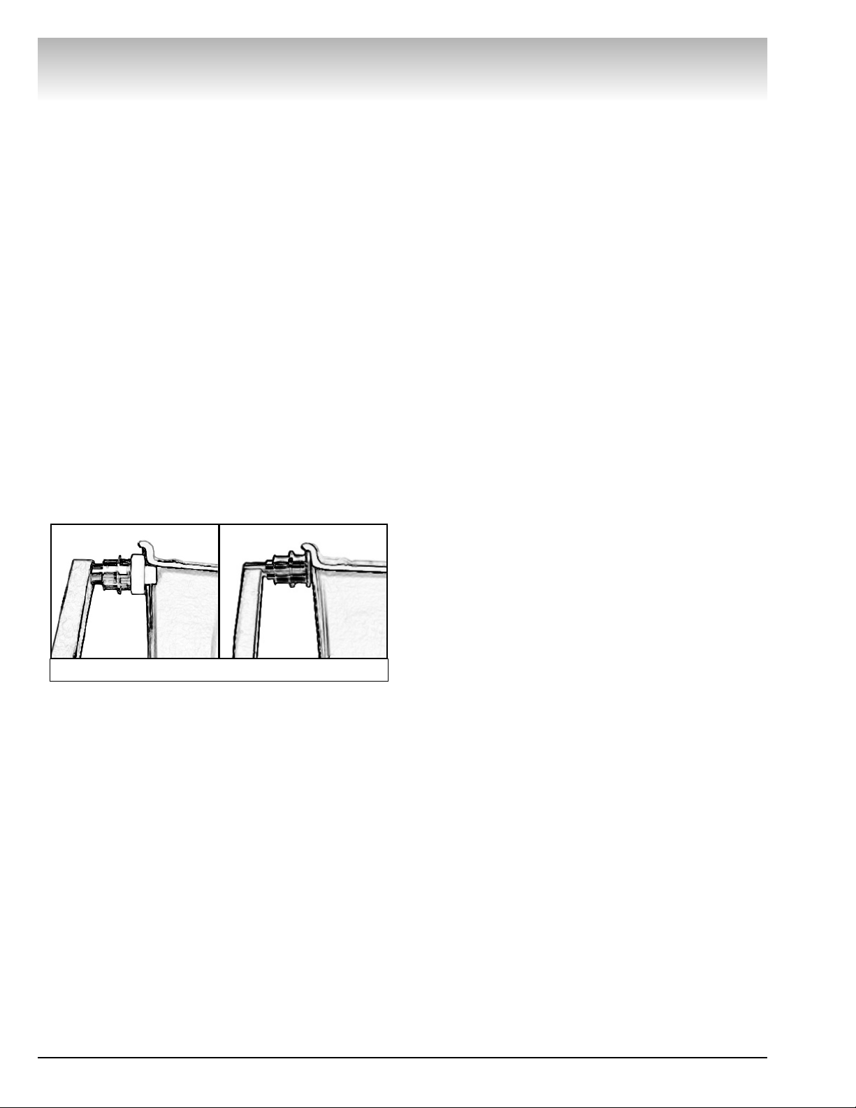
To measure for a clip-on weight location, place the
offset arm at the wheel flange as shown in figure 7A
(metal arm) or figure 7B (plastic arm).
Figure 7A - Clip-on Weight Location Using Metal Offset Arm
Viewed on a Cut-Away Rim for Clarification.
Figure 7B - Clip-on Weight Location Using Plastic Offset Arm
Viewed on a Cut-Away Rim for Clarification.
To measure for a hidden weight location, place the
offset arm at a hidden weight placement location as
shown in figure 8.
Figure 8 - Hidden Weight Location Viewed on a Cut-Away
Rim for Clarification.
Use the offset arm Tape-A-Weight™ feature for accurate placement of hidden weights. See figure 9.
Figure 9 - Hidden Weight Placement Location Viewed on a
Cut-Away Rim for Clarification.
Note: Throughout this manual wheel weights are
referred to as Clip-on or Tape-A-Weight™ (Hidden
Weight). Figure 10 shows an example of each weight.
Figure 10 - Corrective Weight Examples. For Best Results,
use BADA
®
Brand Wheel Weights.
Wheel Flange
Wheel Flange
Hidden Weight
Placement Location
Location for
Hidden Weight
Clip-on Weight
Tape-A-Weight™
Page 14
8 • Important: Always read and follow the on-screen operating instructions.
Video Balancer
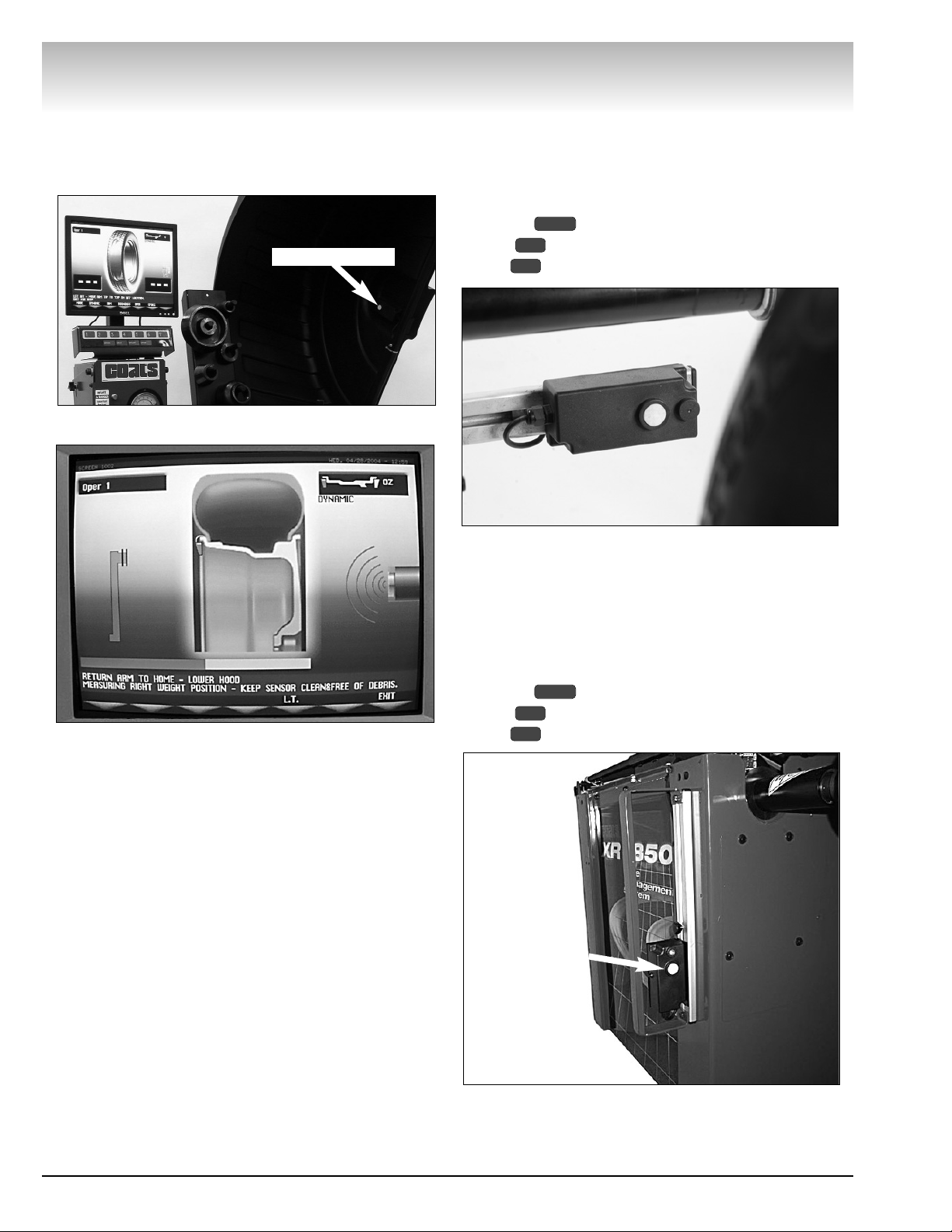
Sensor Measuring Systems
By lowering the hood, measure wheel width automatically using the Tire Width Sensor. See figures 10
and 11.
Figure 10 - Tire Width Sensor
Figure 11 - Screen with Width Sensor Icon
The sensor, shown in figure 12, is mounted on an
adjustable slide at rear of machine and is used to
measure radial runout of the tire when the eye of the
sensor is centered on the tread width.
Important: To activate the radial runout function,
press the button, select the GENERAL SET-UP
option , and set the RUNOUT UNLOADED
option to SONAR.
Figure 12 - Radial Runout Sensor
The sensor, on especially equipped models, (shown
in figure 13) is mounted on an adjustable slide and is
used to measure lateral runout of the tire when the eye
of the sensor is centered on the flat of the tire sidewall.
Important: To activate the lateral runout function,
press the button, select the GENERAL SET-UP
option , and set the RUNOUT UNLOADED
option to SONAR.
Figure 13 - Lateral Runout Sensor
6
5
MENU
7
5
MENU
Lateral Runout
Sensor
Tire Width Sensor
Page 15
Important: Always read and follow the on-screen operating instructions. • 9
Printer
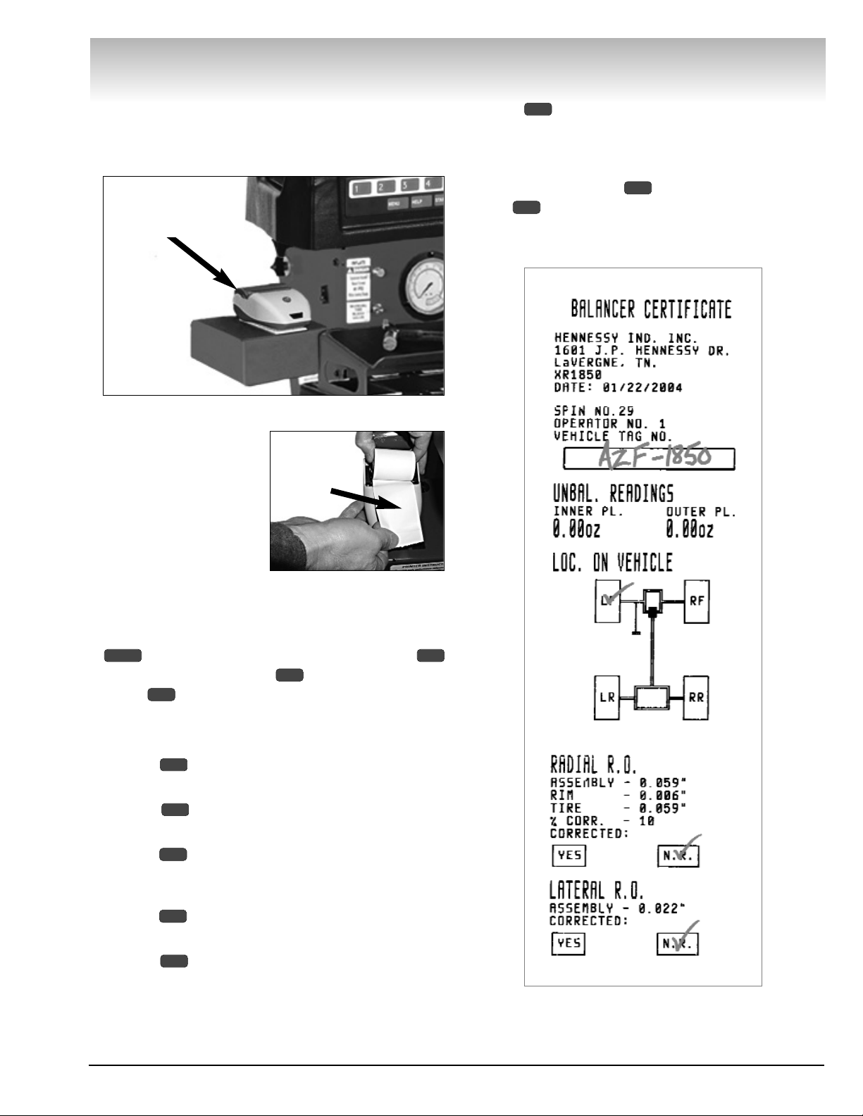
Use the printer, on especially equipped models,
(shown in figure 14) to provide a BALANCER CERTIFICATE for the wheel balance service.
Figure 14 - Printer
Important: The software will not recognize
the printer unless there
is paper in the printer.
This is also the case if
the paper is threaded
between the paper roller
and the printer top cover.
The flashing LED on front of printer indicates power
to the printer, but the printer could still be incorrectly
connected or out of paper.
Important: To activate the printer function, press the
button, select the GENERAL SET-UP option
select the PRINTER option , and set the PRINTER
option to ON.
Also, toggle ON or OFF the following printer options
for the printout (default is ON for all these options):
Option OWNER ADDRESS - prints the owner’s
address (see page 15 to customize to the machine).
Option SPIN NO. - records the spin no. from
CYCLE HISTORY (see page 16 for more information).
Option OPERATOR NO. - indicates the operator
number and name (see page 17 to customize to the
machine).
Option VEHICLE TAG NO. - provides a space for
the operator to write in the vehicle tag number.
Option LOC. ON VEHICLE - operator uses this
diagram to manually check the wheel location that was
serviced.
Option CORRECTED - operator uses this area to
manually check either YES if runout was corrected or
N.R. if not required.
On selected screens, to print the BALANCER CERTIFICATE press option . Note that the printout
option CORRECTED is only available for RUNOUT
DIAGNOSTIC (see MATCHING on page 20 for more
information).
Figure 15 - Completed Printer Balancer Certificate
7
6
7
6
5
4
3
2
1
5
MENU 5
Video Balancer
Printer
Install Roll of
Thermal Paper
Page 16

10 • Important: Always read and follow the on-screen operating instructions.
Video Balancer
Understanding the
Video Display Screens
The video display screens provide access to functions, options, and on-screen instructions for the operator. See figure 19 for the Monitor and Initial Screen
Feature Reference.
1. Access additional functions by pressing one of the
following four keys, at the bottom of the monitor.
- brings up a menu screen. Press MENU again
(toggle) to return to the previous screen.
- provides on-screen help instructions for the
current screen.
- begins a measurement cycle, if the hood is
lowered.
- stops a measurement cycle or exits a screen
as noted in instructions.
2. To select a screen option, press the numbered key
that corresponds with the key icon along the bottom of
each video display screen. See figure 16.
Figure 16 - Select an Option by Pressing Its Corresponding
Numbered Key
3. Always refer to the screen dialogue area for
important operating instructions.
4. Refer to the Mode Icon in the upper right hand
corner of the screen for mode and weight placement
type.
Mode Icon Examples:
5. An option with the symbol indicates the pres-
ence of additional screens. In the example below,
press key to view the next screen.
Menu Option Example:
6. At the weight placement screen align the weight
placement arrows for correct positioning of hidden
weights. See figures 17 and 18.
Figure 17 - Weight Placement Arrows in 3D Mode.
Figure 18 - Weight Placement Arrows in Profile Mode.
1
STOP
START
HELP
MENU
Page 17

Important: Always read and follow the on-screen operating instructions. • 11
Video Balancer
On-screen
Instructions
Operator Display
Weight
Display
DIM
Icon
*
Mode
Icon
Static Unbalance Icon
(appears when over
1.1 oz is present)
Econo Balance Mode
Icon (If feature is
available and enabled)
* Profile Tire Image
RO Max.
(Instant Reading of
Wheel Runout)
* On selected
screens, can toggle
to a 3D tire image.
Numbered Key
Key Icons
Monitor and Initial Screen Feature Reference
Option Key
Screen Option
Weight
Placement
Arrow
Centering Bar
Weight
Location
Icons
Figure 19 - Monitor and Initial Screen Feature Reference
Static-on-Screen™
Page 18

12 • Important: Always read and follow the on-screen operating instructions.
Video Balancer
Runout
Runout Unloaded SONAR
Runout Unloaded SONAR
Runout diagnostic ON
Runout Limits
4
3
2
1
See page 14
for additional
information.
Menu Screen Flowchart
Press the key for the Menu screen to access
balancer function screens and to set configuration
screens. See the flowchart below.
MENU
Cycle History
Spins between calibrations 1000
Daily Spins Nr.: 34
Spins since Calibration: 75
Total Spins Nr.: 81
1
General Set-up
Language English
Screensave time 0 min.
Clock setting
Video sleep mode time 60 min.
Excessive static unbalance ON
Printer
Runout
5
4
7
6
3
2
1
Clock Setting
Month: 7
Day: 24
Year: 2004
Hour: 15
Minutes: 5
Day: THU
12/24 Hour Clock: 24
7
6
5
4
3
2
1
Balancing Set-up
Display Units oz
Lower Weight Limit 0.25 oz
Calculation Roundoff 0.25
Start by Lowering Hood ON
Sound Signal ON
Econo Bal Lower Wt Limit 0.64 oz
7
5
6
4
3
2
1
Menu
Optimization (Match Balance)
Runout (Runout Match)
Cycle History
Service Adjustments
General Set-up
Balancing Set-up
Special Functions
2
7
6
5
4
3
1
1
3
4
5
6
7
See 15 for
additional infor-
mation.
See page 14
for additional
information.
See page 16
for additional
information.
2
PASSWORD
PASSWORD
PASSWORD
(If feature is available
and enabled)
Page 19

Important: Always read and follow the on-screen operating instructions. • 13
Video Balancer
Service Adjustments
Distance Arm Calibration
Width Sonar Calibration
Diameter Arm Calibration
Distance/Diameter Arm Type Metal
Temperature 70º F
3
5
7
2
1
Distance Arm Calibration
On-screen Instructions
Width Sonar Calibration
On-screen Instructions
Optimization
(Match Balance)
On-screen Instructions
Alphabet Entry
On-screen Instructions
Alphabet Entry
On-screen Instructions
Self-Test Screen
Diameter Arm Calibration
On-screen Instructions
Machine Self-Calibration
On-screen Instructions
Special Functions
Owner Address
Operators Name
Machine Self-Test
Static Unbalance Displayed ON
Stop On Top OFF
Machine Self-calibration
6
5
4
3
2
1
See page 27
for additional
information.
See page 21
for additional
information.
See page 15
for additional
information.
Printer
Printer ON
Owner Address ON
Spin No. ON
Operator No. ON
Vehicle Tag No. ON
Loc. on Vehicle ON
Corrected ON
5
4
3
2
1
6
7
See page 14
for additional
information.
Graph Screen
On-screen Instructions
See page 22
for additional
information.
Runout Limits
Max. True Runout Limit 0.050"
Rim Runout Limit 0.010"
Correction Runout Limit 0.030"
3
2
1
PASSWORD
Page 20

Balancer Function Set-
up and Review
See the Menu Screen Flowchart on page 12 and 13 for
screen access information.
Indicates recommended settings.
General Set-up
Press the key and select the GENERAL SET-UP
option for the following menu selections.
Figure 20 - General Set-up Screen
Language - Toggle to display English, Español, or
Français.
Set to ENGLISH.
Screensave time -
Set from 1 to 10 minutes @ 1
minute increments.
Clock setting -
Set the month, day, year, hour,
minutes, day, and 12/24 hour clock.
Figure 21 - Clock Setting Screen
Video sleep mode time -
Set the range from 0
through 60 minutes.
Set to 60 min.
Excessive Static Unbalance -
Toggle ON or OFF to
detect whether the static unbalance limit is
exceeded.
Set to ON.
Printer -
Toggle ON or OFF to set the printer,
owner address, spin no., operator no., vehicle tag
no., loc. on vehicle, and corrected options.
See PRINTER on page 9 for further details.
Figure 22 - Printer Screen
Runout -
Set runout options from this menu.
Figure 23A - Runout Screen
Runout Unloaded -
(lateral) toggle to
OFF or SONAR.
Set to OFF for the XR
1800 Model! Set to ON for the XR
1850 Model!
Runout Unloaded -
(radial) toggle to
set to OFF or SONAR.
Set to SONAR.
Runout Diagnostic - Toggle ON or OFF.
See MATCHING pg. 20 for further details.
Runout Limits - Tolerances that indicate
the limit of runout allowed on the
tire/wheel. Set tolerances within the following range:
Note: See MATCHING on page 20 for further details.
4
3
2
1
7
6
5
4
3
2
1
5
MENU
14 • Important: Always read and follow the on-screen operating instructions.
Video Balancer
Shown with Recommended Settings
Shown with Recommended Settings
Page 21

Important: Always read and follow the on-screen operating instructions. • 15
Video Balancer
Select RUNOUT LIMITS option for runout menu:
Max. True Runout Limit -
Tolerance
that indicates the limit of runout
allowed on the tire/wheel.
Rim Runout Limit -
Tolerance that
indicates runout limit allowed on rim.
Correction Runout Limit -
Tolerance
that indicates the limit of runout
allowed on the tire/wheel.
Figure 23B - Runout Limits Screen
Balancing Set-up
Press the key and select the BALANCING SET-
UP option for the following menu selections.
Figure 24 - Balancing Set-up Screen
Display Units - Toggle to set OZ (ounce) or G
(gram) weight measurements.
Lower Weight Limit - Set the limit within the following tolerances:
0.13 - 0.50 oz (ounces) @ 0.01 increments
4 - 10 g (grams) @ 1 gram increments
Note: The closer the Lower Weight Limit is set to
0.13 oz (4 g) the more respins you will have when
attaching 0.25 oz (5 g) weights.
Calculation Roundoff -Toggles the display of wei
ght corrections roundoff from 0.25 OZ (most whe
els) to 0.50 OZ (heavy wheels).
Start by Lowering Hood - Toggle ON or OFF.
Sound Signal - Toggle ON or OFF. Enable for an a
udible beep when a
key is pressed, dimensions are acquired (automat
ic mode), correct weight placement is reached (m
easurement screen), and correct weight applicati
on point is reached (positioning screen).
Econo Balance Lower Weight Limit (if feature
is available and enabled) - Set limit within the
following tolerances:
0.20 - 0.90 oz (ounces) @ 0.01 increments
4 - 25 g (grams) @ 1 gram increments
Special Functions
Press the key and select the SPECIAL FUNC-
TIONS option for the following menu selections.
Figure 25 - Special Functions Screen
Customize the machine by following the on-screen
instructions for functions and/or .
Owner Address - This information appears on the
screensaver. It consists of three lines, each a
maximum of 30 characters.
Operators Name -
Enter up to four different
machine user names, each a maximum of 15
characters.
Follow the on-screen instructions to
complete the customization.
Figure 26 - Operator Name Entry Screen
2
7
5
1
1 2
7
MENU
4
3
3
4
2
1
2
1
6
MENU
Shown with Recommended Settings
Shown with Recommended Settings
Shown with Recommended Settings
Page 22

16 • Important: Always read and follow the on-screen operating instructions.
Video Balancer
Machine Self-Test -
Provides software version,
technical, and other machine diagnostic information (DIAGNOSTIC PROCEDURES section page
34).
Static Unbalance Displayed -
Toggles the display of
the Static-on-Screen™ value ON or OFF.
Set to ON.
Stop On Top -
Toggle ON or OFF to automatically
stop the wheel near TDC (top-dead-center) for
outer weight placement.
Set to OFF.
Machine Self-calibration -
Calibrates the weight
amount and placement. See MACHINE SELF-CALIBRATION AND SERVICE ADJUSTMENTS on page
26 for more information.
Additional Functions
Press the key and select the CYCLE HISTORY
option for the following menu.
Figure 27 - Cycle History Screen
Cycle History -
Select
option to set the
number of spins between calibrations (500 - 5000
@ 500 spin increments).
Also, the operator can view the following information
when the CYCLE HISTORY option is selected.
• The number of daily spins that is automatically
reset after switching the machine off.
• View the number of spins since calibration.
• View the total number of spins.
Advanced Balancing
Functions
This wheel balancer enables you to balance a variety
of wheel configurations. Read through this section, it
will help you determine which mode and options are
best suited for certain wheel assemblies.
Remember: As with any balancing procedure, first
remove any weights attached to the wheel, inspect the
tire and wheel, and use the most appropriate balancer
mounting method before beginning.
Initial Screen Options
At the initial screen (see page 11), press the numbered key that corresponds with the key icon along the
bottom of the video display screen for the following
options.
Mode - select from several balancing types and
weight placement locations.
Figure 28 - Modes Screen
Dynamic - the “initial screen” is a dynamic balance mode using two clip-on weight locations.
Note: To reset the mode back to the initial screen at
any time, press the DYNAMIC option , or turn the
machine OFF then ON. Note that if an operator is in a
balance mode, it may be necessary to finish the balance cycle first.
DIM - (available in 3D view) select to enter dimensions manually. See MANUALLY SETTING
WHEEL DIMENSIONS on page 23 for further
details.
3
2
2
1
3
6
5
4
MENU
3
3 1
3
Shown with Recommended Settings
Page 23

Check-Spin - press to save 2 to 3 seconds of
time when a balancing wheel. This option eliminates the runout measurement during the CheckSpin.
Roundoff - toggle between 0.25-ounce or 0.01ounce weight increments.
Oper - (available in 3D view) used to cycle
through (recall) an operator’s memorized measurements. This wheel balancer can be used simultaneously by four operators. See SPECIAL
FUNCTIONS on page 15 for further details.
OZ/g - (available in PROFILE view) toggle
between ounce or gram weight measurements.
Printer - (available in 3D view) prints a certificate
with important balancing information. See
PRINTER on page 9 for further details.
Profile or 3D - Toggle between a profile or 3D tire
image for weight placement.
Figure 30 - The Profile and 3D Icons
Dynamic Modes
Clip-on Weights - the initial screen. This mode is
used for most passenger and light truck tire assemblies using the most common location for corrective
weights. Clip-on weights are placed
on the inner and outer rim flanges.
Note: To reset the mode back to the initial screen at
any time, press the DYNAMIC option , or turn the
machine OFF then ON. Note that if an operator is in a
balance mode, it may be necessary to finish the balance cycle first.
Have the following items handy: steel rim passenger
or light truck tire wheel assembly mounted on the balancer and clip-on weights.
Figure 31 - Clip-on Weight Placement Screen
ALU modes - Select the MODE option for the
modes menu. All the ALU modes are dynamic balance.
Choose the option that best fits the available weight
locations.
- ALU-1
- ALU-2
- ALU-3
- ALU-4
Have the following items handy: an appropriate
wheel assembly mounted on the balancer and Tape-AWeights™. You must use the appropriate measurement and weight placement technique for each plane
selection (page 7) to balance the wheel.
4
3
2
1
1
2
7
6
5
5
4
3
Important: Always read and follow the on-screen operating instructions. • 17
Video Balancer
Profile
3D
Page 24

Static Modes
Choose a static balance for wheel assemblies that
are not possible to balance dynamically or for narrow
wheels. For example, a motorcycle wheel that has a
small wheel width.
Select the MODE option for the modes menu
and then select the STATIC MODES option .
Choose the option that best fits the available weight
locations.
a. For a “single weight”, choose any one plane location.
b. For “two weights”, choose any two plane locations.
Using this approach can reduce the amount of induced
dynamic unbalance by splitting the correctional weight
value among two different planes.
- STATIC1
- STATIC2
- STATIC3
- STATIC4
Have the following items handy: an appropriate wheel
assembly mounted on the balancer and a selection of
weights.
Special Modes
Select the MODE option for the modes menu.
Select the SPECIAL MODES option to choose a
mode for the following special type wheel assemblies.
PAX Balance - Select the appropriate option for the
PAX wheel that best fits the available weight locations.
- PAX1
- PAX2
Have the following items handy: a PAX wheel assembly mounted on the balancer and a selection of Tape-AWeights™.
Patch Weight Balance - Use a static patch weight balance when there is a very large unbalance in a tire
assembly or if a very large tire has a large unbalance. A
weighted balance pad (patch weight) is placed inside the
tire in the center to compensate for the large unbalance.
- PATCH (static)
- DIAMETER ↑
Have the following items handy: measuring tape and
various patch weight sizes.
Note: Before proceeding with Patch Weight Balance,
it is recommended that you use the Optimization
(Match Balance) procedure first, see page 21, in order
to use the smallest patch weight.
The Patch Weight Balance involves the loosening of tire beads and the inflation of a tire.
Training is necessary in tire changer operation and understanding the dangers
involved during bead seating and tire inflation before attempting this stage of the
Patch Weight Balance procedure. Read the
operators manual supplied with the tire
changer and consult a supervisor.
The patch weight balance steps are as follows:
1. Measure the out-
side tire diameter, see
figure 32, and enter this
diameter manually on
the patch menu screen,
DIAMETER option .
Figure 32 - Measure Outside Tire Diameter
2. Select PATCH option . The balancer automati-
cally sets itself for a STATIC balance.
Figure 33 - Patch Screen
3. Move the offset arm tip to the inside of rim to set
tape-a-weight™ location. Wait for beep.
4. Spin the wheel.
5. Align the on-screen arrows. Next, mark the tire at
12 o’clock. Then remove the wheel assembly from the
machine.
6. Disassemble the tire and rim. Place patch weight
in the tire at location marked on the tire. Reassemble
tire and rim matching the marks on the tire and rim.
7. Complete by balancing the wheel assembly fol-
lowing normal procedures.
3
4
WARNING
4
3
2
1
7
1
4
3
2
1
6
1
18 • Important: Always read and follow the on-screen operating instructions.
Video Balancer
Outside
Diameter
Page 25

Important: Always read and follow the on-screen operating instructions. • 19
Video Balancer
Additional Options
Be aware of the following options that appear on
selected screens. Press the numbered key that corresponds with the key icon for each additional option
described below.
OZ/g - toggle between ounce or gram weight
measurements. Note that this option appears on
the weight placement screen (profile view) after
the wheel has been spun.
Spoke -To balance with adhesive weights located
behind the spokes in the outer correction plane.
The spoke balance steps are as follows:
1. Begin by balancing the wheel assembly following
normal procedures for either the ALU-1 or ALU-2
mode.
2. When the unbalance is displayed, attach the left
side corrective weight.
3. Next, select SPOKE option .
4. Rotate the wheel to position the right side yellow
marker (ball) until it turns green. Select NEXT option
.
5. Rotate tire toward you until the first spoke is at 12
o’clock or TDC. Hold location and press .
6. Rotate tire away from you (past unbalance point)
until the next spoke is at 12 o’clock or TDC. Hold location and press .
7. Observe, by rotating the tire, that there are now
two hidden weight locations located behind the two
specified spokes (3D mode), See figure 34. Use the
offset arm to attach the two right side corrective
weights.
Figure 34 - Spoke Weight Placement Screen
Unspoke - If you decide not to use the spoke
option, press this option. Only one right side
marker (ball) will display.
Printer - (available in 3D view) prints a certificate
with important balancing information. Note that
this option appears on matching screen. See
PRINTER on page 9 for further details.
L.T. - For one spin only, press this to change the
weight roundoff from 0.25 oz. to 0.5 oz. Note that
this Light Truck option shows up after taking a
dimension reading with the offset arm.
Figure 35 - The L.T. Icon Indicates Weight Roundoff Change
Econo Balance Mode (if available, model number supports EB) -
Toggle the Econo Balance Mode
ON or OFF.
Set to OFF.
EB (Econo Balance) is an alternate approach to balancing a tire and wheel assembly. The technology
seeks first to eliminate the static imbalance in a wheel
assembly then, based on several parameters, calculates the minimum amount of corrective weight
needed to bring dynamic imbalance within acceptable
limits.
Balancing wheel assemblies using EB mode often
results in the application of less corrective weight. In
addition to the potential productivity savings due to a
reduction in the number of “re-spins” necessary to
achieve an acceptable balance condition.
5
6
6
6
2
1
6
6
6
5
L.T. Icon
Page 26

20 • Important: Always read and follow the on-screen operating instructions.
Video Balancer
Matching
A matching procedure may involve the loosening of tire beads and the inflation of a tire.
Training is necessary in tire changer operation and understanding the dangers
involved during bead seating and tire inflation before attempting this stage of a
matching procedure. Read the operators
manual supplied with the tire changer and
consult a supervisor.
The operator can choose from two procedures to correct for a runout condition. Typically, if the static limit
unbalance is exceeded, the operator will choose
Optimization (Match Balance) to correct the situation.
Or, if the radial runout limit is exceeded, the operator
will choose to use the Runout (Runout Match) procedure to correct the situation.
Whenever a large unbalance or runout condition is
detected, a runout procedure can be accessed manually by selecting the button and then either the
OPTIMIZATION (MATCH BALANCE) option or the
the RUNOUT (RUNOUT MATCH) option .
To view the Static-on-Screen™ value, press the
key, select the SPECIAL FUNCTIONS option , and
set the STATIC UNBALANCE DISPLAYED option
to ON. The Static-on-Screen™ reading, see page 11,
will appear in the upper left-hand side of the screen.
Automatic Runout Detection
The wheel balancer software can be set to automatically detect a wheel assembly that exceeds the static
limit unbalance or radial runout limit. A Runout
Diagnostic screen will appear, see figure 36, that provides on-screen information for the operator.
Figure 36 - Runout Diagnostic Screen
To set the wheel balancer to automatically detect
runout, press the button, select the BALANCING SET-UP option , and set the RUNOUT DIAGNOSTIC option to ON.
When the Runout Diagnostic option is ON, the radial
runout sensor should also be set. Press the button, select the GENERAL SET-UP option , and set
the RUNOUT UNLOADED option to SONAR.
The Runout Diagnostic screen will always appear
when the measured runout exceeds the MAX. TRUE
RUNOUT LIMIT setting. To change this setting, press
the button, select the BALANCING SET-UP
option , and select the RUNOUT LIMITS option
. Then select the MAX. TRUE RUNOUT LIMIT
option ; press and hold the button down to scroll
to the desired amount.
Note: If the Runout Diagnostic screen appears and
the runout is below the set limit, it is because the static
unbalance exceeds 3.00 ounces. In this case, consider
the OPTIMIZATION (MATCH BALANCE) procedure to
correct the condition.
Also at the runout limits screen (RUNOUT LIMITS
option ), select the RIM RUNOUT LIMIT option
to scroll to the desired rim tolerance amount and
select the CORRECTION RUNOUT LIMIT option
to scroll to the desired tire/wheel tolerance amount.
3
2
7
1
7
6
MENU
7
5
MENU
5
6
MENU
WARNING
MENU
1
2
MENU
7
4
Page 27

Important: Always read and follow the on-screen operating instructions. • 21
Video Balancer
Optimization (Match Balance)
The Tire/Rim Weight Optimization procedure is used
to determine the best mating of tire and rim that will
result in the least amount of total unbalance of the
assembly. It requires two spins and two rotations of
the tire on the rim. Optimization may be needed when:
• The customer complains of ride problems.
• The balancer calls for total static weights in excess
of 3 ounces (85 grams) on passenger car tires.
To set the wheel balancer to automatically detect an
excessive static unbalance, press the button,
select the GENERAL SET-UP option , and set the
EXCESSIVE STATIC UNBALANCE option to ON. A
screen (see fig. 37A) will appear when the excessive
static unbalance is detected.
Figure 37A - Excessive Static Unbalance Screen
Note: A high unbalance may indicate the improper
mounting of the assembly on the balancer, or a rim
that is out of round or misformed, or a tire with a bubble or other problem. If the unbalance is excessive, it
may be prudent to replace the rim, the tire, or both. If
either is replaced, do not continue with optimization.
Balance the new tire and rim and evaluate the readings.
To check for machine/wheel mounting errors, select
CHECK MTG. at the Excessive Static Unbalance
screen and follow the on-screen instructions.
If you choose to use Optimization, then select the
key for the menu screen, and then select the
OPTIMIZATION (MATCH BALANCE) option .
Follow the on-screen instructions for the TIRE/RIM
WEIGHT OPTIMIZATION procedure as outlined in
the following steps.
Figure 37B - Tire/Rim Weight Optimization Screen
Note: Use this procedure only after the wheel has
spun and weights are displayed.
1. Rotate arrow on faceplate to 12 o’clock. Place a
mark (backside of the wheel) on the rim at 12 o’clock.
Press the NEXT option .
2. Remove the wheel assembly from the balancer.
3. Using a tire changer, rotate the tire 180 degrees
on the rim.
4. Replace wheel assembly on balancer and align the
faceplate arrow with the mark on rim. Lower the hood
and press the NEXT option . The wheel spins.
5. Rotate the wheel until a red box appears at the
yellow arrows. Put a second mark (frontside of wheel)
on the rim at 12 o’clock.
6. Rotate the wheel until a red box appears at the
green arrows. Put a third mark (frontside of wheel) on
the tire at 12 o’clock. Press the NEXT option .
Note: The rim unbalance and tire unbalance values
are displayed on the screen.
7. Remove wheel assembly from balancer.
8. Using a tire changer, align the mark on the rim
with mark on the tire.
9. Replace the wheel assembly on the balancer.
Align the faceplate arrow with the previous mark (backside) on the rim to check improvement or just continue
with step 10.
10. Press NEXT option and balance the assembly.
1
1
1
1
1
2
5
5
MENU
MENU
Page 28

22 • Important: Always read and follow the on-screen operating instructions.
Video Balancer
Runout (Runout Match)
Select the button and then the RUNOUT
(RUNOUT MATCHING) option or, if the wheel balancer software is set to automatically detect runout,
select GRAPH at the Runout Diagnostic screen.
Figure 38 - Select Graph at the Runout Diagnostic Screen
Evaluate runout information at the “graph”
screen, see figure 39. The red curve in the upper
graph is the average radial runout of the assembly
that is how much the runout of the assembly mimics running “off-center”. The red curve in the lower
graph is the average lateral runout of the assembly
and a large number here indicates a bent rim,
deformed sidewall, or both.
Figure 39 - Runout Measurement Screen
1. At the “graph” screen, select Rim to evaluate the
rim verses the tire radial runout. Follow the on-screen
instructions.
2. Touch the rim with the diameter arm.
Note: Place the offset arm, as shown on-screen, just
under the inside of the barrel of the rim and hold in
place. Do not place the offset arm at the clip-on
weight location.
3. Press and turn the wheel slowly.
Note: Hold the offset arm in place one revolution until
you reach 100%. Your progress is displayed on-screen.
The wheel balancer software calculates and displays
a possible assembly runout reduction in inches based
on the suggested tire on rim positioning. At this point,
based on the possible reduction, choose to continue or
exit the procedure. If the reduction amount does not
exceed the CORRECTION RUNOUT LIMIT setting, the
screen will display “Assembly Cannot Be Corrected by
Matching”.
4. 1. Mark tire and rim in the suggested position.
To mark the tire position, rotate the wheel in the
direction of the black arrows until the red “chalk” icon
appears on the tire. Step on the positioning pedal, then
mark the tire on the outside at top-dead-center.
Figure 40 - “Chalk” Icon to Indicate TDC Tire Position
To mark the rim position, rotate the wheel in the
direction of the blue arrows until the red “chalk” icon
appears on the rim. Step on the positioning pedal, then
mark the rim on the outside at top-dead-center.
5. 2. Rotate tire on rim to align the two marks.
Remove the wheel from the balancer. Using the tire
changer, break down the assembly and position the
tire and rim so that the marks line up. The tire is now
optimized.
Complete by balancing the wheel assembly following
normal procedures.
START
1
2
MENU
Page 29

Important: Always read and follow the on-screen operating instructions. • 23
Manually Setting Wheel
Dimensions (DIM)
Definition of dimensions (DIM):
A = Offset The distance measured from the bal-
ancer (“0” on the offset arm) to the inner
plane of the rim (inner weight location).
W = Width The width of the wheel at the rim
flanges, measured with the calipers as
shown in figure 42.
Note: Only use calipers provided by the wheel bal-
ancer manufacturer because others may not be the
same.
D = Diameter The diameter of the wheel as indi-
cated on the tire.
Figure 41 - Manual Measurements Screen
When necessary, the wheel dimensions can be
inserted or edited in manual mode. At the initial screen
or during calibrations follow these instructions onscreen when setting DIM option .
Manually Setting “A” DIM
1. Press SELECT option to highlight (in red) the
rim offset (A) DIM.
2. Position offset arm at clip-on weight location on
wheel and read the number, on the slide out offset
arm, at the cabinet (this is the correct offset DIM).
3. Using + or - , manually set the offset
DIM on-screen (highlighted red) to match the offset
number of the mounted tire.
Manually Setting “W” DIM
1. Press SELECT option to highlight (in red) the
rim width (W) DIM.
2. Use the plastic calipers provided with the wheel
balancer to measure the wheel width.
Figure 42 - Caliper Location Diagrams
3. Using + or - , manually set the rim width
DIM on-screen (highlighted red) to match the measured caliper width of the mounted rim.
Manually Setting “D” DIM
1. Press SELECT option to highlight (in red) the
rim diameter (D) DIM.
2. Inspect mounted tire sidewall to determine the
exact diameter that is printed on the tire.
3. Using + or - , manually set the tire diam-
eter DIM on-screen (highlighted red) to match the tire
sidewall size.
3
4
5 6
4
65
4
65
Video Balancer
Steel Wheels
Alloy Wheels
W
A
D
Page 30

24 • Important: Always read and follow the on-screen operating instructions.
Video Balancer
Mounting Wheel on
Spindle Shaft
Avoid back injury, seek assistance when lifting heavy tire/rim assemblies onto the balancer shaft.
Select the most appropriate mounting method for the
wheel you are balancing. Using the proper method
ensures secure mounting and safe balancer operation,
and prevents damage to the wheel.
On most wheels, the inner side of the wheel hub
usually has the most uniform surface for wheel balancing. Always center the wheel by the most uniform
shaped side of the hub to achieve the most accurate
balance.
Regardless of mounting type, always make sure that
the wheel is forced firmly against the shaft faceplate
and that the hub nut engages the threaded shaft for at
least four complete turns. To assist in centering the
wheel properly, rotate the wheel and the shaft while
tightening the hub nut.
Standard Back Cone Mounting
Most original equipment and steel wheels can be
mounted properly using this method. The wheel is centered on a cone from the inner side of the hub.
1. Select the cone that best fits the center hole in
the wheel. Slide the cone onto the shaft with the large
end towards the faceplate.
2. Lift the wheel onto the shaft and center it on the
cone.
3. Attach the pressure cup to the hub nut and install
the assembly onto the shaft. Tighten securely.
Figure 43 - Back Cone Mounting
CAUTION
Captured
Cone
Spring
Quick Lock
Hub Nut and
Pressure Cup
Cone
Protective
Ring
Shaft
Page 31

Important: Always read and follow the on-screen operating instructions. • 25
Standard Front Cone Mounting
A wheel should be centered by the outer side of the
hub only when the inner surface will not provide an
accurate surface to center on.
1. Select the cone that best fits the center hole in
the wheel.
2. Lift the wheel onto the shaft and slide it back
against the shaft faceplate.
3. Slide the cone onto the shaft and into the center
of the wheel. You will need to lift the tire to seat the
cone in the center hole.
4. Install the hub nut (without pressure cup) onto the
shaft. Tighten it securely against the cone.
Figure 44 - Front Cone Mounting
Alternate Mounting
If the wheel has a protruding outer hub which will not
permit the use of the pressure cup, or the cup will not
permit the hub nut to engage at least four turns of the
shaft, this alternate method should be used.
1. Select the cone that best fits the center hole in
the wheel. Slide the cone onto the shaft with the large
end towards the faceplate.
2. Lift the wheel onto the shaft and center it on the
cone.
3. Use the small nylon spacer (no-mar ring) or a cen-
tering cone to press against the outer wheel hub.
4. Install the hub nut (without the pressure cup) onto
the shaft. Tighten securely.
Figure 45 - Alternate Mounting
Video Balancer
Captured
Cone
Spring
Quick Lock
Hub Nut
Cone
Shaft
Captured
Cone
Spring
Quick Lock
Hub Nut
Cone
No-Mar
Ring
Shaft
Page 32

26 • Important: Always read and follow the on-screen operating instructions.
Video Balancer
Machine Self-calibration
and Service Adjustments
The wheel balancer provides step by step on-screen
instructions for MACHINE SELF-CALIBRATION and
SPECIAL ADJUSTMENTS. Choose MACHINE SELFCALIBRATION when on numerous wheels a one-spin
balance is not achievable. Choose SPECIAL ADJUSTMENTS when components are added or replaced that
may effect machine dimension measurements.
Machine Self-calibration
Important: Prior to performing the machine self-cali-
bration, refer to the functional check for calibration on
the back cover.
To access the Machine Self-calibration menu, press
the key, then select SPECIAL FUNCTIONS
option and choose MACHINE SELF-CALIBRATION selection . Follow these instructions on-
screen:
1. DO NOT CALIBRATE UNTIL YOU HAVE
CHECKED THE FOLLOWING:
• Check Stub Shaft Tightness
• Check for Proper Mounting of Tire/Wheel and for
Speed-Nut Slippage
• Manually Check Wheel Dimensions: Check That
It Matches The Wheel Dimension Icon Within
Approx. 1/4-inch.
• Perform Functional Check Per Procedure
• Check for Proper Phase at Machine Self-Test
Screen
To check for these causes press EXIT or press NEXT
to continue.
2. Mount a 14", 15", or 16" steel wheel with tire. A
balanced tire/wheel works best. Press NEXT option
to continue.
3. At this DIM screen manually set the dimensions
carefully before proceeding. See MANUALLY SETTING
WHEEL DIMENSIONS (DIM) on page 23 for further
instructions. Press NEXT option to continue.
Important: Dimensions must match the “calibration
wheel”. A dimension cannot be zero.
4. Lower the hood; then press the key.
5. After spin, raise the hood and add test weight to
outside flange at any location: 4.00 oz. (Be sure there
are no weights at same location on the inside rim
flange.)
6. Lower the hood; then press the key.
7. After spin, raise the hood and remove the test
weight on the outside flange and place it directly
across on the inside flange.
Figure 46A - Test Weight Inside Flange Position
8. Lower the hood; then press the key.
9. Raise the hood, rotate the wheel until the test
weight is at 12 o’clock or TDC and hold at this position.
Note: Step 8 is important, do not skip it.
10. While holding at the TDC position, press NEXT
option .
Figure 46B - Test Weight Inside Flange Position
11. Calibration Accepted, press NEXT to EXIT
Machine Self-calibration.
1
1
6
7
MENU
1
START
START
START
Page 33

Important: Always read and follow the on-screen operating instructions. • 27
Video Balancer
Service Adjustments
Press the key and select SERVICE ADJUST-
MENTS option for the following menu selections.
Important: These service adjustments are password
protected. Contact your factory trained COATS®
Service Technician before attempting any upgrade or
repair that may affect the machine dimension measurement system.
Figure 47 - Service Adjustments Screen
Distance Arm Calibration - Calibrates the
distance part of the offset arm.
Width Sonar Calibration - Calibrates the
width using a sensor.
Diameter Arm Calibration - Calibrates the
diameter part of the offset arm.
Distance/Diameter Arm Type - Toggle to
METAL or PLASTIC. Set to match the style/type of
arm installed on the balancer.
Temperature - Ambient temperature setting
for sonar. Recommended setting is 70˚ F.
Distance Arm Calibration
Note: Calibrate the offset arm first, since it is very
important that the wheel dimensions are correct.
Follow these instructions on-screen when calibrating
the DISTANCE ARM CALIBRATION option :
1. Move offset arm to position 0 on gauge, hold and
press NEXT option .
2. Move offset arm to position 6 (not 0.6-inch) on
gauge, hold and press NEXT option .
Note: Position the gauge as shown in figure 48.
Figure 48 - Distance Arm Calibration
3. Return offset arm to home position.
4. Calibration Accepted.
5. Press NEXT option to return to Service
Adjustments.
Width Sonar Calibration (If equipped)
Follow these instructions on-screen when calibrating
the WIDTH SONAR CALIBRATION option :
1. Move the arm gauge to front of faceplate (outer
edge of large diameter). Hold at position and press
NEXT option .
Note: It is highly important to position the gauge cor-
rectly as shown in figure 49A (plastic arm) or figure
49B (metal arm).
Figure 49A - Plastic Offset Arm Gauge to Faceplate
1
2
1
4
MENU
1
1
1
1
2
3
5
7
Gauge
Set to 6
Gauge
Set to 0
Shown with Recommended Settings
Page 34

28 • Important: Always read and follow the on-screen operating instructions.
Video Balancer
Figure 49B - Metal Offset Arm Gauge to Faceplate
2. Return offset arm to home position.
3. Pull out and position the Calibration Target Bracket
to front of faceplate.
4. Leave in position and close the hood.
Note: The Calibration Target Bracket, shown in cali-
bration position in figure 50, is used to allow the width
sonar to measure the distance to the balancer faceplate during calibration.
Figure 50 - Target Bracket Positioned for Calibration
5. Screen indicates “Reading Value”.
6. Raise the hood and return the Width Sonar
Calibration Bracket to the stored position.
7. Calibration accepted.
8. Return sensor target bracket to stored position
then press NEXT option to return to Service
Adjustments.
Note: The sonar calibration target bracket is stored
flush with the side of cabinet at all other times, see figure 51.
Figure 51- Sonar Target Bracket in Stored Position
Diameter Arm Calibration (Plastic)
Note: Be sure the correct Distance/Diameter Arm
Type is set (See Service Adjustments page 27).
Follow these instructions on-screen when calibrating
the DIAMETER ARM CALIBRATION option (plastic arm type):
1. Mount a 14", 15", or 16" steel wheel with tire.
2. Using the + or -, set the diameter to the same
diameter as rim.
3. Press NEXT option .
Note: The diameter will display on the screen.
4. Position offset arm at clip-on weight location on
wheel.
Figure 52 - Diameter Arm (Plastic) Calibration
5. Hold at location and press NEXT option .
6. Screen indicates “Reading Value”.
7. Return offset arm to home position.
8. Calibration Accepted.
9. Press NEXT option to return to Service
Adjustments or option to EXIT.
7
1
1
3
1
1
Calibration
Target Bracket
Calibration
Target Bracket in
Stored Position
Width
Sensor
Page 35

Important: Always read and follow the on-screen operating instructions. • 29
Diameter Arm Calibration (Metal)
Note: Be sure the correct Distance/Diameter Arm
Type is set (See Service Adjustments page 27).
Follow these instructions on-screen when calibrating
the DIAMETER ARM CALIBRATION option (metal
arm type):
1. Position the arm roller at upper position on the
faceplate hub with the tip on back of flange.
2. Hold at position and press NEXT option .
Note: The position will display on the screen.
Figure 53 - Hold Roller Tip At Upper Position And Press
NEXT
3. Rotate and position the arm roller at lower posi-
tion on the faceplate hub with the tip on back of flange.
4. Hold at position and press NEXT option .
Note: The position will display on the screen.
Figure 54 - Hold Roller Tip At Lower Position And Press
NEXT
5. Return offset arm to home position.
6. Calibration Accepted.
7. Press NEXT option to return to Service
Adjustments or option to EXIT.
Diagnostic Procedures
After Balance Vibration Problems
If vibration is still present after balancing the wheels
and driving the vehicle on smooth pavement, remove
the wheels and recheck the balance. If a wheel is out
of balance the cause maybe:
• Wheel was not mounted/centered correctly on the
balancer.
• A weight has come off the wheel (possibly the
wrong clip style). Remove the other weights from
the wheel and rebalance.
• Foreign material inside the tire. Remove the tire
from the wheel, remove the foreign material, and
remount. Remove wheel weights and rebalance
the wheel.
• Stones or other foreign objects caught in the tire
tread or rim. Remove the objects. Check and rebalance if needed.
If the balancer still indicates the wheels are balanced
to within 0.05 ounces on both inner and outer displays,
the problem is not in the balance of the wheels. Check
the following possible sources of vibration:
• Tire pressure. Bring all tires up to the recommended PSI.
• Radial or lateral runout in the tire or wheel. Replace
the damaged part.
• Unbalance in wheel covers or trim rings. Remove
the wheel covers or trim rings and test drive. If the
vibration is gone, remove the shaft and use an
appropriate adapter to mount the wheel to the balancer. Balance the wheel with the wheel cover or
trim ring attached to the wheel.
• Incorrectly mounted wheel. Remount correctly.
• Damaged wheel bolt holes. Replace wheel.
• Worn universal joints. Replace as required.
• Drive shaft unbalance or damaged. Balance, repair,
or replace.
• Unbalance in brake rotor(s) or drum(s).
• Suspension out of alignment. Align the vehicle and
replace any damaged or worn parts.
1
7
1
1
3
Video Balancer
Page 36

30 • Important: Always read and follow the on-screen operating instructions.
Video Balancer
Troubleshooting
A COATS®Service Technician may ask for information
to help diagnose service concerns. Conveying this
information to your service technician prior to servicing
can help to expedite service to your equipment.
Although much of the diagnostic information aids your
COATS®Service Technician, several remedies for balancer misfunctions are available to the operator.
Note: Always EXIT error message and repeat function to see if error is eliminated.
The following lists error screens (numbered) that may
appear indicating a problem with the balancer.
Figure 55 - Example Error Screen
Error
No
Video
Err. 1
Err. 2
Symptom
The balancer does not turn on.
Rotation signal missing.
Wheel spins too fast & no
brake.
Balancer does not start.
Motor turns nut no rotation.
Too low speed when taking the
measurement.
During turns to measure the
unbalance value, the wheel
speed has gone below 42 r.p.m.
Check
1. Check for proper connection to the power supply.
2. Check and replace fuses on the power PCB if necessary.
3. Check the monitor function - press monitor menu button. (see trouble shooting tips)
4. Check control transformer output.
5. Check FS1 & FS2 fuses on power PCB.
6. Check power cable to main PCB & output at power PCB.
7. Replace power PCB.
8. Replace the main PCB.
1. Check the belt tightness.
2. Encoder disconnected, bad or damaged wiring, failed optical unit no reset signal.
3. Check hood switch operation.
4. Replace the encoder unit.
5. Motor disconnected or bad wiring - check for motor voltage at power
PCB - check circuit breaker - check machine power.
6. If motor hums - remove belt and check for motor rotation at pulley if rotation, replace capacitor.
7. Check for faulty power PCB or main PCB.
1. Very light / small wheel mounted on balancer - not enough inertia to
keep wheel rotating.
2. Check belt tightening.
3. Check the operation and adjustment of the encoder and in particular, the reset signal. (in MACHINE SELF-TEST, Pos counts from 0 to
255 and then 0 again). UP = cw, DOWN = ccw.
4. Replace the main PCB.
Page 37

Important: Always read and follow the on-screen operating instructions. • 31
Video Balancer
Error
Err. 3
Err. 4
Err. 5
Err. 6
Err. 7 /
Err. 8
Err. 9
Err. 11
Err. 12
Symptom
Calculation Error.
Incorrect Machine SelfCalibration.
Counterclockwise rotation.
After pushing the wheel
turns in the opposite direction.
Wheel guard hood open or the
button has been pushed
without closing the wheel
guard hood.
Ram Error or defect.
Reading error of NOVRAM
parameters.
Access error in NOVRAM
parameters writing.
High speed error.
During rotation to measure the
unbalance value, the wheel
speed has gone over 270 r.p.m.
Error in the unbalance measuring cycle.
START
START
Check
1. Check the wheel dimensions setting.
2. Check the piezo pick-ups connections - electrical & mechanical. (in
MACHINE SELF-TEST, push on spindle shaft and verify that both
piezo outputs change.
3. Execute the 4-ounce weight (machine self-calibration).
4. Mount a wheel having a known unbalance (lower than 4.00 ounces
or 100 grams) and check the balancer reading.
5. Replace the PC board.
1. In MACHINE SELF-TEST - check the operation of UP/DOWN - RESET
signals of the encoder.
2. Check the connection of the motor for rotation.
1. Reset the error by pushing button = .
2. Close the wheel guard hood and press button.
3. Check operation of the wheel guard micro-switch.
4. Press the button.
1. Reset NOVRAM & check operation or Replace PCB.
1. Repeat the entire balancer calibration.
2. Switch the balancer OFF.
3. Wait a minimum time of 1 minute (approx).
4. Switch the balancer ON and check the proper operation.
5. Replace the PCB board.
1. Replace the PCB board.
1. Check for possible damage or dirt on the encoder disc - clean dirt
with a soft cloth - blow air across the optical units.
2. Check the operation and adjustment of the encoder and in particular, of the reset signal. (in MACHINE SELF-TEST, Pos counts from 0
to 255 and then 0 again). UP = cw. DOWN = ccw.
3. Replace the main PCB.
1. Press and respin. Check PHASE in MACHINE SELF-TEST, if
180 deg diff., recalibrate & check piezos..
2. Check encoder adjustment and operation. (clearance .020” to .035”)
3. Check motor operation.
4. Check belt tightness.
5. Check hub nut tightness.
6. Replace the main PCB.
EXIT
START
START
7 EXIT
Page 38

32 • Important: Always read and follow the on-screen operating instructions.
Video Balancer
Error
Err.13
Err.14
Err.17
Err.18
Err.15 /
Err.16 /
Err.19
Err.20
Err. 30
Err.40,
41, 42,
43
Err.45,
46, 47,
48
Err.50,
51, 52,
53
Err.54
Symptom
Error in the unbalance measurement.
Over ranging - too much unbalance
Wheel stopped before it was
positioned or before taking
runout reading.
Clock error
Error in the creating of the
runout graph.
Error in the reading of the values which are used to create
the runout graph.
Error in the writing procedure of
the cursor for the current value
of the runout graph.
Error in the Sonar reading.
Sonar did not read any value.
Check
1. Press and respin. Check PHASE, VCO, VCI in MACHINE SELF-TEST.
2. Check the piezo pick-ups connection. (electrical & mechanical)
3. Check the balancer spindle connections.
4. Mount a wheel having a known unbalance (lower than 3.5oz or 100
grams) and check the balancer readings.
5. Replace the PC board.
A.) Follow screen instructions for “heavy side” down balancing to bring
wheel unbalance into range and then balance normally.
B.) Follow instructions 1 thru 5 above.
1. Wheel too light - not enough inertia. Use heavier wheel.
2. Check positioning of sonar unit behind wheel.
1. Replace the PC board
1. Execute a new runout measurement.
1. Execute a new runout measurement.
1. Execute a new runout measurement.
1. Before taking the measurement, make sure that the RADIAL
RUNOUT SONAR is properly positioned.
2. Check the RADIAL RUNOUT SONAR connection. Unplug and replug at
pwer PCB.
3. Check the power supplies on the power board.
4. Replace the RADIAL RUNOUT SONAR.
5. Check that the wheel doesn’t stop before making at least 4 to 5
complete turns after the first breaking impulse.
6. Check belt tightening.
7. Replace the PC board
EXIT
Page 39

Important: Always read and follow the on-screen operating instructions. • 33
Video Balancer
Error
Err.55
Err.56
Err.57
Err.58
Err.59
Err.65
Symptom
Error in the Sonar reading.
The values taken by the Sonar
are insufficient for a correct
runout measurement.
Error in Lateral Sonar reading.
Sonar did not read any value.
Error int the Lateral Sonar reading. The values taken by the
Sonar are insufficient for a correct Lateral Runout measurement.
Error in Radial and Lateral Sonar
reading. No value was read by
the Radial and Lateral Sonars.
Error in the Radial and Lateral
Sonar reading. The values taken
by the Radial and Lateral Sonars
are insufficient for a correct
Runout measurement.
Printer Not Connected.
Check
1. Before taking the measurement, make sure that the RADIAL
RUNOUT SONAR is properly positioned.
2. Check that the wheel doesn’t stop before making at least 4 to 5
complete turns after the first breaking impulse.
3. Check belt tightening.
4. Fit a medium-sized wheel (14” x 5-3/4”) and execute an eccentricity
measurement. If error 55 doesn’t take place anymore, it means that
the inertia of the wheel that gave the problem is the cause of the
wheel stopping before the acquisition of the minimum number of
values necessary for a reliable runout measurement.
1. Before taking the measurement, make sure that the LATERAL
RUNOUT SONAR is properly positioned.
2. Check the LATERAL RUNOUT SONAR connection. Unplug and
replug at power PCB.
3. Check the power supplies on the power board.
4. Replace the Lateral Runout Sonar.
5. Check that the wheel doesn’t stop before making at least 3 com-
plete turns after the first braking pulse.
6. Check the belt tightening.
7. Replace the PC board.
1. Before taking the measurement, make sure that the LATERAL
RUNOUT SONAR is properly positioned.
2. Check that the wheel doesn’t stop before making at least 3 com-
plete turns after the first braking pulse.
3. Check the belt tightening.
4. Fit a medium-sized wheel (14” x 5-3/4”) and execute a lateral runout
measurement. If error 57 doesn’t take place anymore, it means that
the inertia of the wheel that gave the problem is the cause of the
wheel stopping before the acquisition of the minimum number of
values necessary for a reliable runout measurement.
1. Check actions in Error 54.
2. Check actions in Error 56..
1. Check actions in Error 55.
2. Check actions in Error 57..
1. Check serial connector at computer PCB.
2. Check serial connections inside cabinet at wire tray.
Page 40

34 • Important: Always read and follow the on-screen operating instructions.
Video Balancer
Machine Self-Test “Green Screen”
In the event of faulty wheel balancer operation, notify
a COATS®Service Technician of all the machine self
test readings. To view the self test screen, press the
key, select Special Functions option , and
select Machine Self-Test option
.
Figure 56 - Machine Self-Test Screen
A - This line provides software version and other tech-
nical information.
B (Pos.) - An encoder check. The word UP should
appear when rotated clockwise and DOWN when
rotated in the opposite direction.
C (Dist) - Check for correct operation of the distance
arm gauge; the number increases when the gauge is
pulled out.
D (Sonar 1) - Check of the hood width sensor
(option): the number decreases when a surface is
brought closer to the sensor device.
E (Vco I) - Piezo Output.
F (Diam) - Check for correct operation of the diame-
ter gauge; the number increases when the offset arm
is rotated outward.
G (Sonar 2) - Check of the radial runout sensor
(option): the number decreases when a surface is
brought closer to the sensor device.
H (Vco E) - Piezo Output.
J (Sonar 3) - Check of the lateral runout sensor
(option): the number decreases when a surface is
brought closer to the sensor device.
K - Toggle the Sonar 1/3 screen option ,to view
either Sonar 1 or Sonar 3 diagnostic information.
3
7MENU
6
Page 41

Important: Always read and follow the on-screen operating instructions. • 35
Video Balancer
Maintenance
Instructions
The balancer requires only minor maintenance to
keep the unit operating properly.
1. Keep the display clean and clear. Use a vaporizing
cleaner only. Do not use cleaners or solvents which
leave oily or filmy residues behind.
2. Keep the adapters, cones, faceplate, threaded
shaft, pressure cup, and hub nut clean. Grease and dirt
buildup will cause inaccurate balancing and premature
wear. Clean these items at least once a day with a
vaporizing solvent.
3. Clean the weight tray, accessory posts, pegs, and
storage shelves with a vaporizing solvent. Weights
stored in a dirty tray may pick up grease and dirt which
may keep them from securely attaching to the wheel.
Do not hose down with water or bucket
wash the balancer. Extensive damage to the
balancer will result. Sensitive electronic
components, wiring harnesses, and other
devices housed in the balancer are not
intended to be exposed to water.
Exposing the balancer to water, either by
hose or bucket, or by exposure to rain or
snow, may cause risk of shock or electrocution to operator or bystanders. Place, store,
and operate the balancer only in a dry, sheltered location.
4. Clean the sensor unit(s) using only a soft, water-
dampened cloth (not wet). Do not use solvents as they
may damage the white sensor area.
5. Keep the area around the balancer clear. Remove
any tools or other items that are leaning against the
balancer. Keep the area under the balancer clear.
Remove any items that may cause the balancer to not
sit level. Be particularly cautious of new or used wheel
weights on the floor, as they may cause personal injury
due to falls.
6. Use only COATS®accessories. Accessories from
other manufacturers may not fit or function properly,
and may damage the balancer.
Monitor Screen Adjustment
The monitor control panel buttons are located on the
monitor.
Figure 57 - Monitor Control Panel Buttons
WARNING
CAUTION
Monitor Control
Panel Buttons
Page 42

36 • Important: Always read and follow the on-screen operating instructions.
Video Balancer
Installation Instructions
Receiving
The shipment should be thoroughly inspected as
soon as it is received. The signed bill of lading is
acknowledgement, for the carrier, of receipt in good
condition of the shipment covered by our invoice.
If any of the goods called for on this bill of lading are
shorted or damaged, do not accept them until the carrier makes a notation of the shorted or damaged goods
on the freight bill. Do this for your own protection.
NOTIFY THE CARRIER AT ONCE if any hidden loss or
damage is discovered after receipt and request him to
make an inspection. If the carrier will not do so, prepare an affidavit to the effect that you have so notified
the carrier (on a certain date) and that he has failed to
comply with your request.
IT IS DIFFICULT TO COLLECT FOR LOSS OR DAMAGE AFTER YOU HAVE GIVEN THE CARRIER A CLEAR
RECEIPT.
File your claim with the carrier promptly. Support your
claim with copies of the bill of lading, freight bill,
invoice, and photographs, if possible.
Although COATS responsibility ceases upon delivery
of the shipment to the carrier, we will gladly assist in
tracing lost shipments. Our willingness to assist in
every possible manner does not make COATS responsible for collection of claims, or replacement of lost or
damaged materials.
Electrical Requirements
The wheel balancer requires a 115 VAC, 60HZ, single-
phase power. Plugs into standard 15 amp outlet.
Always have a qualified electrician install 3-prong
receptacles in accordance with state and local codes.
Some special order wheel balancers may require different voltages. See serial tag for the appropriate
power requirements of your machine.
Setup
Do not use the monitor, monitor base,
accessory storage, faceplate, hood or shaft
to lift the balancer.
Do not attempt to install and setup the unit
yourself. Contact COATS
®
as noted below.
A factory trained COATS®Service Technician must
perform the install, setup, and initial test procedures
on your wheel balancer. Do not attempt to install and
setup the unit yourself. Accurate and reliable operation
of your unit depends on proper installation. Please contact COATS®directly at 1-800-688-9240 for the
Certified Service Partner nearest you.
Air Supply Connection
The wheel balancer requires a minimum 2 CFM air
source at 60 PSI. This system is only intended for
adjusting the inflation of tires.
Connect to Power
Your factory trained COATS®Service Technician
should do the final check to verify the power installation before connecting the balancer to a power supply.
Failure due to improper power connection may void
the warranty.
CAUTION
CAUTION
Page 43

Important: Always read and follow the on-screen operating instructions. • 37
Video Balancer
Floor and Space Requirements
The balancer must be located on a flat floor of solid
construction, preferably concrete. The balancer must
sit solidly on its three feet. If the balancer is not level,
does not sit solidly on its three feet, or is placed on an
unstable floor, the balancer will not function properly
and may produce inaccurate balance readings.
Do not operate the balancer while it is on the pallet.
Select a location for the balancer that provides a level,
solid floor, and adequate clearance around and above
the balancer. Make sure the location selected has
enough room above and behind the unit so the hood
can be raised completely. The location must also provide working room for mounting and removing wheels.
Make sure the area has adequate lighting.
6 foot
6 foot
7 foot
Figure 58 - Footprint Diagram
Page 44

38 • Important: Always read and follow the on-screen operating instructions.
Video Balancer
Specifications
Cycle Time
8 seconds (average 50 pound tire)
Maximum Outside Tire Diameter
44 inches
Maximum Tire/Wheel Weight
160 pounds (72 kg)
Wheel Diameter Range (with Offset Arm or
Manual)
10 - 24 inches
Wheel Width Range
2 - 20 inches
Balancing Display Increments
0.25 or 0.01 ounces
Resolution (Non-Round Off Mode)
0.01 ounce, position 0.70 degrees
Resolution (Round Off Mode)
0.25 ounce, position 0.70 degrees
Temperature at Balancer Location
50 degrees - 105 degrees Fahrenheit
Mounting Shaft Diameter
40 MM standard
Electrical (115 V, 1 Ph, 60 Hz)
standard 15 AMP 3-prong outlet
Shipping Weight
680 pounds (308 Kg)
Net Weight with Standard Accessories
465 pounds (211 Kg)
Balancer RPM
185 - 205 RPM
Features
• LCD Monitor with Swivel Adjustment
• Automatic Data Entry for Offset, Width, and
Diameter - Manual Entry Backup on all Parameters
• Interactive Screens for all Modes and Functions
with Superior Graphic Displays
• Static-on-Screen™
• Four Fixed Function Keys, Seven Program Keys for
user Friendly Operation
• Many Balancing Modes
Dynamic (Standard): Clip-on Weights
4 Alloy: User Defined
2 PAX: User Defined
4 Static
Patch (Tire Weight): Static Only
Behind the Spoke Weight Placement
(All Modes with Inside Wheel Weights)
• Auto Start When Hood is Lowered
• Vertical Wheel Mounting System
• Single Spin Balancing - Dynamic and Static
• Easy-To-Read Position Indicators
• Interactive Tape-A-Weight™ Placement with Offset
Arm
• Cone Spring Permanently Retained in Faceplate
• Hood Safety Interlock System
• Extended Mounting Faceplate for Deeper Wheels
• Removable Center Shaft for Closed Center Wheels
• Match Mount (Optimization) Function with Weight
Optimization Program
• Can be Programmed for Four Different Users
• User Friendly Weight and Position Calibration
• Easy Calibration of Automatic Data Entry Devices
• No Bolt-down Installation
• Solid State Motor Control
• Econo Balance Mode (if available, model number
supports EB)
• UL/CSA Listing Pending
Page 45

Important: Always read and follow the on-screen operating instructions. • 39
Video Balancer
Required Accessories
• 3 Piece Graduated Cone Assortment (Small Cone
8112098, Medium Cone 8112099, Large Cone
8112100), 40 MM ID, Hardened and Ground both ID
and OD
• Large Adapter (Truck Cone 8112101)
• Cone Spring (Permanently Retained in Faceplate)
• Quick Lock Hub Nut and Pressure Cup (80180096)
• No-Mar Ring (80180097)
• Rim Width Calipers (8309011)
• Wheel Weight Pliers (8111515)
Optional Accessories
Page 46

40 • Important: Always read and follow the on-screen operating instructions.
Video Balancer
Notes
Page 47

Important: Always read and follow the on-screen operating instructions. • 41
Glossary of Terms
BDC - an acronym for bottom-dead-center, also
referred to as the 6 o’clock position.
Dynamic Balance - balancing a wheel using two
planes for correction. Dynamic balance means the
wheel is in balance when in motion about its rotational
axis. Also, a wheel is statically balanced when dynamically balanced. However, a wheel that is statically balanced is not necessarily dynamically balanced.
Hub Centric - refers to mounting and means the
wheel is centered to the vehicle by the center hole on
the wheel and the pilot on the vehicle axle. The maximum clearance between the wheel’s center hole or
bore and the axle pilot is between 0.0015 and 0.006
normally.
Inner Plane - the closest corrective weight location
from the balancer.
Lug Centric - refers to mounting and means the
wheel is centered by the studs and nuts mounted on
the axle of the vehicle. This is the least desirable way
to mount a wheel; very difficult to maintain the wheel
centering on the vehicle axle.
Offset Arm - pivoting arm that measures A & D
wheel dimensions.
A - distance measured from the balancer
(“0” on the offset arm) to the inner plane of
the rim (inner weight location).
D - diameter of the wheel at the weight
location, which is not always the same as
the bead seat diameter that determines tire
diameter.
W - width between the inner and outer
planes.
Outer Plane - farthest corrective weight location
from the balancer.
Static Balance - balancing a wheel with only a single
corrective weight or splitting two weights at the same
radial location.
TDC - an acronym for top-dead-center, also referred
to as the 12 o’clock position.
Weight Planes - the location for corrective weights.
Video Balancer
Page 48

8113423 11 11/09 © Copyright 2002 Hennessy Industries and COATS All Rights Reserved Printed in USA
 Loading...