

Page 1
1601 J. P. Hennessy Drive, LaVergne, TN USA 37086-3565 615/641-7533 800/688-6359 Manual Part No.: 8107758 01
HENNESSY INDUSTRIES INC. Manufacturer of AMMCO
®
, COATS®and BADA®Automotive Service Equipment and Tools. Revision: 07/02
Speed-Mag Adapter
Set for Center Post
Tire Changers
®
Operating Instructions
with Parts Identification
READ these instructions before placing unit in
service KEEP these and other materials delivered
with the unit in a binder near the machine for
ease of reference by supervisors and operators.
Page 2
Model Usage
This adapter set is for use with 4040SA, 4040A,
3040A, 3030A, 2020, 2020A, 1010 (serial #153601 and
up), and 1010A (serial #12025 and up).
Before You Begin
When working on custom wheels, take your time and
use extreme care in all tire servicing operations to prevent damaging these costly wheels. Read and follow all
the instructions and acquaint yourself with this adapter
before use.
Adapter Usage Instructions
1. Before servicing aluminum or magnesium wheels
with a large rim flange, install the 3/16-inch shim to prevent the lower bead loosener from catching on, or damaging the wheel.
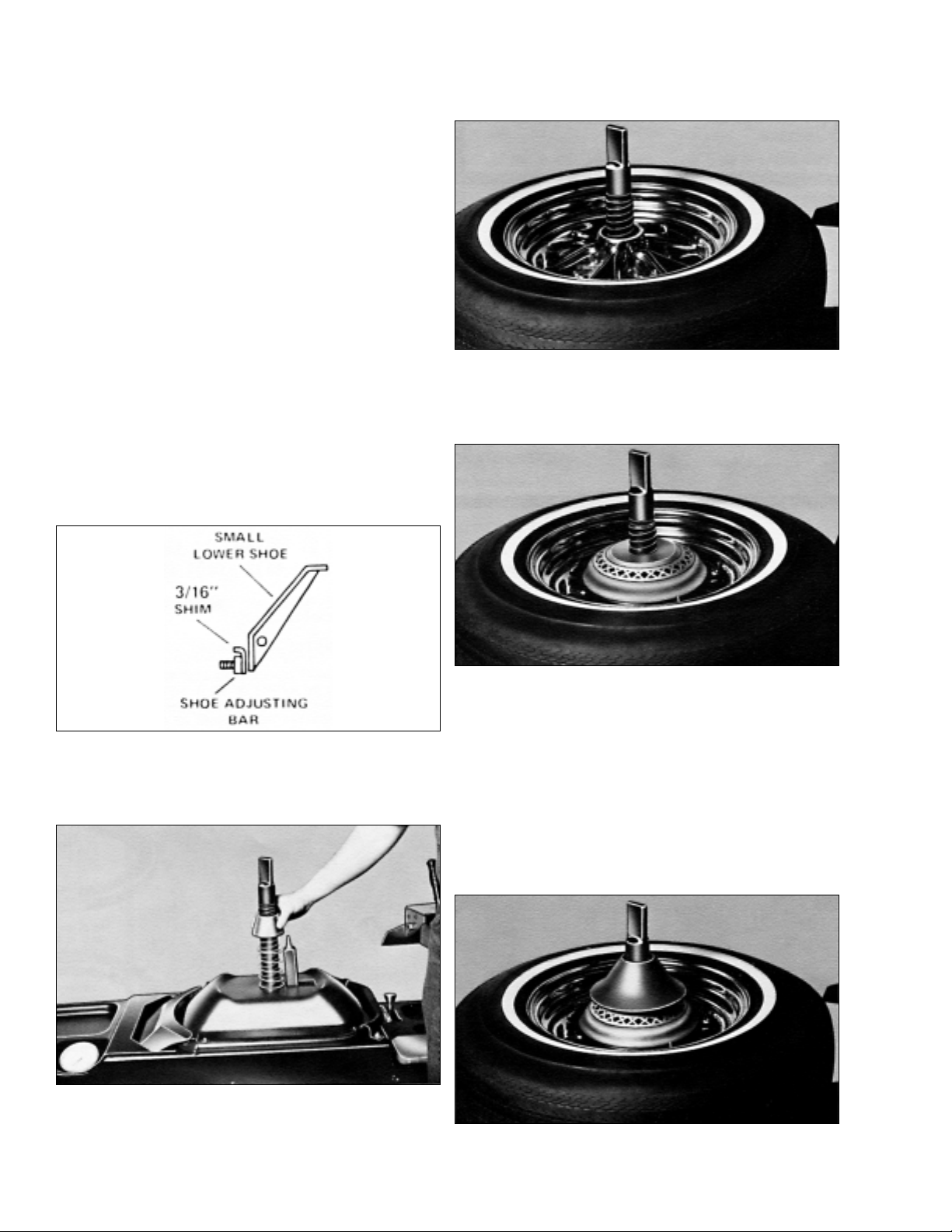
To install 3/16-inch Shim: Depress the foot pedal until
the cylinder reaches the top of its stroke. Lay the lower
bead loosener shoe back and place the shim between
the small lower shoe and the shoe adjusting bar (figure
1). When loosening beads on wide flanged rims, watch
the small lower shoe and make certain it clears the rim
flange. If it does not, use the 1/4-inch shim or combine
both shims. Do not use shims on steel wheels.
Figure 1 - Installation of Shim
2. Place the spring and positioning cone over the center post onto the table. The small end of the cone
points upward (figure 2).
Figure 2 - Place Spring and Positioning Cone on Post
3. Place the wheel over the center post onto the
table top, guiding the positioning pin into a lug hole. Be
sure the valve stem is in front of the operator.
Figure 3 - Place Wheel on Table Top
4. Place the adapter plate over the center post onto
the wheel with the large side (cushion side) down.
Figure 4 - Place Adapter Plate Over Wheel
Note: On some high center hub wheels where the
adapter assembly touches the hub of the wheel, the
spacer cushion must be used. Place the cushion on the
wheel, ledge side up, and place the adapter plate on top
of the cushion.
5. Turn the tire changer hold down cone over and
thread it onto the center post. Tighten it down securely
onto the adapter plate. Be sure the hold down cone is
tight.
Figure 5 - Thread Hold Down Cone Onto Post and Tighten
Page 3

6. On models 1010, 1010A, 2020, 2020A, 3030A and
3040A, install the black upper bead loosener protector
on the upper bead loosener nose to protect the wheel
from possible marring by the bead loosener guide.
Place the upper bead loosener shoe on the tire next to,
but not on, the rim. Be sure the top bead loosener
guide is engaged on the rim (figure 6). Depress the
foot pedal until both bead looseners complete their full
strokes. If the top bead is not completely loosened,
release the foot pedal until the machine completes the
full return cycle, then
depress the foot pedal
again. The ratchet effect of
the upper bead loosener will
deliver a deeper stroke.
Important: Use the second stroke only if the upper
bead is not completely loosened by the first stroke.
Figure 6 - Install Protector on Upper Bead Loosener
7. Check detent control knob for proper setting.
Forward is used for all tire and rim combinations
except 15-inch x 4-inch - 4-1/2-inch, 16-inch x 5-inch - 51/2-inch, and 17.5-inch x 5-1/2-inch - 6-1/2-inch.
Relocate detent knob by pushing it down and moving
forward or backward to the proper setting.
Figure 7 - Position Detent Knob
8. Install the combination tool end protectors.
Figure 8 - Install Tool Protectors
9. Demount the tire in the usual manner. Make certain the plastic protector is positioned to completely
cover the end of the tool. Always apply plenty of rubber lubricant to tire beads.
Figure 9 - Demount the Tire
10. Mount the tire in the usual manner. Make certain the plastic protector is positioned to completely
cover the end of the tool. Always apply plenty of rubber lubricant to tire beads.
Figure 10 - Mount the Tire
Styled Steel Wheels
1. Place wheel over center post onto table top.
Guide the positioning pin into a lug hole.
2. Slide styled steel wheel adapter tube over post
and into wheel center hole (flange up).
Figure 11 - Install Styled Steel Wheel Adpater Flange Up
3. Invert the hold down cone and tighten the assembly to the table top.
Figure 12 - Install Hold Down Cone
4. Mount and demount tire as usual.
Page 4

Small Lower Bead Loosener Shoe
Adjustment
Important: Before attempting to loosen beads, make
sure small lower bead loosener shoe is in adjustment.
1. Clamp a 13-inch, 14-inch, or 15-inch wheel, with-
out tire, on the table top.
2. Depress the foot pedal and cycle the bead
loosener shoe through to the top of its stroke. Watch
closely and inspect the shoe/wheel clearance.
Clearance between the shoe and the wheel rim flange
should be approximately 1/16-inch to 1/8-inch at all
points across the shoe edge. If the clearance is out of
range evenly across the shoe, it can be adjusted. If the
clearance is uneven across the shoe, it has been damaged and must be straightened or replaced.
3. Adjust shoe by loosening the 3/8-inch c 1-1/4-inch
self-tapping bolt located just below the shoes on the
end of the power arm (figure 13). Add or remove shims
turning the small lower shoe into adjustment. Addition
of shims will increase the clearance, and removal of
shims will decrease the clearance. Additional shims
are available.
4. Retighten the self tapping bolt and recheck shoe
adjustment.
Tire failure under pressure can be hazardous. Inspect the tire carefully for wear or
defects before seating or inflating. Never
use pressure beyond the tire industry recommendation of 40 PSI. Always lubricate
with approved lubricant and never damage
beads. Keep hands and entire body back
from inflating or inflated tire.
Special Safety Instructions
1. Never stand with any part of your body over the
tire during inflation process.
2. Before starting, release all air from the tire.
3. Place wheel on the table top with the narrow,
mounting side of the wheel up.
4. Position tire with valve stem directly in front of
operator.
5. Hand tighten hold down cone or adapter before
breaking beads, mounting, or demounting.
6. Use approved lubricant on all beads before seat-
ing, mounting, or demounting.
7. On units with Air-flate, depress inflation pedal only
when seating or inflating the tire.
8. Loosen hold down cone on full turn immediately
after obtaining initial bead seal and before attempting
further inflation.
9. To seat beads, use a small amount of air intermittently. Never exceed tire industry recommendation of
40PSI.
10. During inflation, observe pressure frequently
and avoid distraction to prevent over inflation.
11. When using a bead expander band, do not
exceed 5 PSI in the tire when the band is in place.
This instruction booklet is intended to supplement your tire changer operator’s manual. It is not intended to replace it. Always
follow the instructions and safety information provided with your machine to assure
safe operation and prevent accidents and
injuries.
8107758 01 07/02 © COPYRIGHT 1995 HENNESSY INDUSTRIES AND COATS ALL RIGHTS RESERVED PRINTED IN U.S.A.
Parts Identification
Item Part No. Description
1 8106568 Boot Kit, Set of 10 and 2
2 8106144 Adapter Tube, Styled Steel Wheel
3 8102803 Shim, 3/16", Black
4 8102927 Shim, 1/4", Red
5 8102789 Adapter, Eldorado/Toronado
6 8107641 Adapter Plate
7 8107634 Cushion
8 8107636 Positioning Cone
9 8107637 Spring
10 8107734 Spacer Cushion
11 8107689 Hold Down Assembly
12 8107760 Instructions Spacer
DANGER
CAUTION
 Loading...